
Parametric Study of Jet/Droplet Formation Process during LIFT Printing of Living Cell-Laden Bioink

 , , ,
, , , 

Abstract
:1. Introduction
2. Materials and Methods
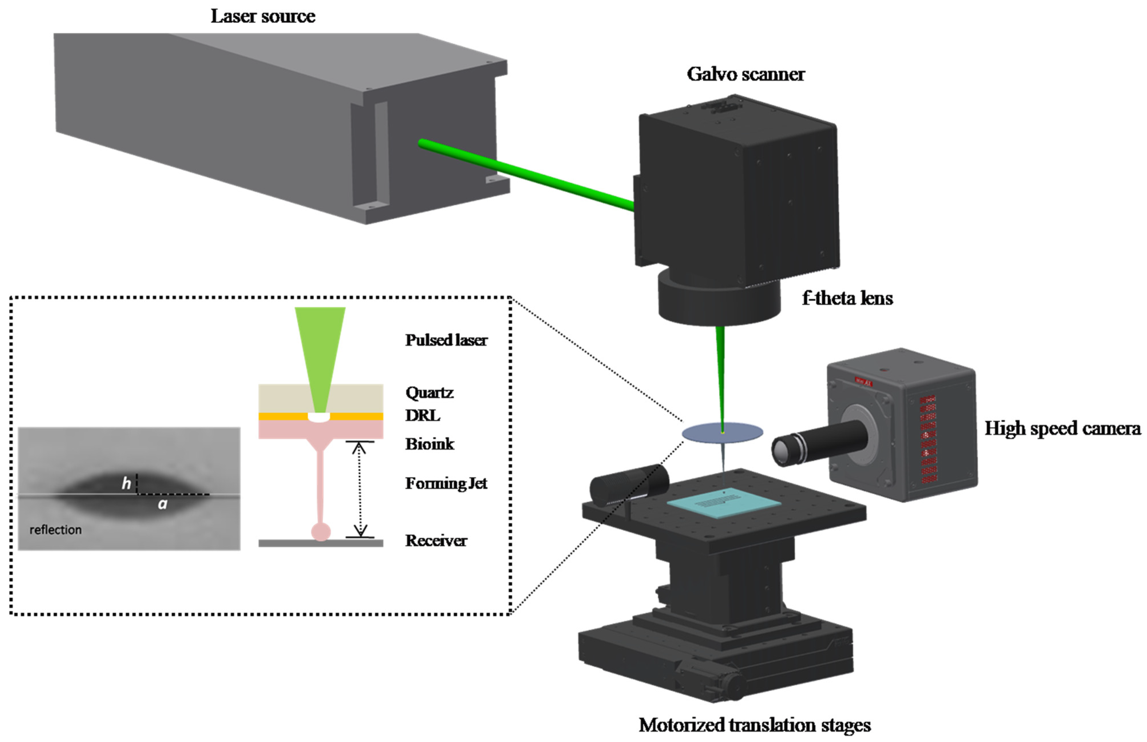
2.1. Experimental Setup
2.2. Cell Culture
2.3. Cell Viability Assay
2.4. Preparation of Donor Substrate
2.5. Preparation of Receiver Substrate
2.6. Bioink Composition
2.7. Measuring Droplet Diameters
2.8. Imaging and Analysis
2.9. Statistical Analysis
3. Results and Discussion
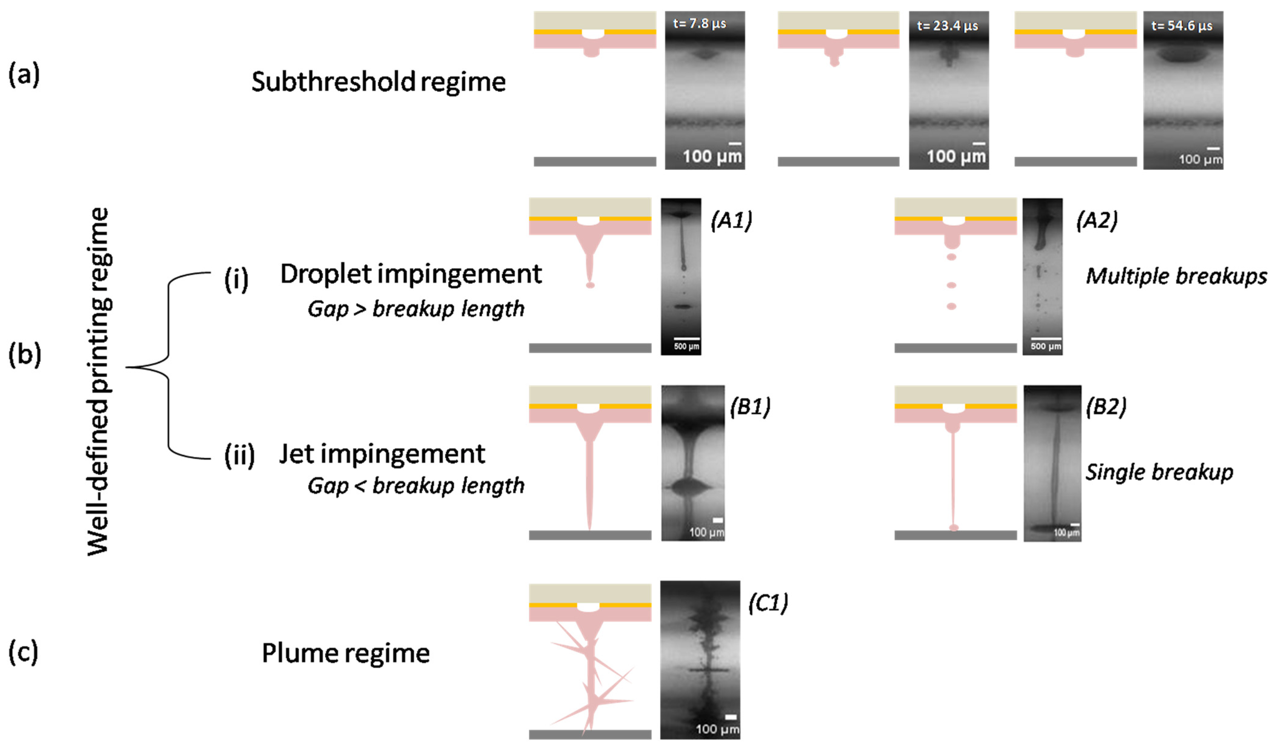
3.1. Ejection Mechanism
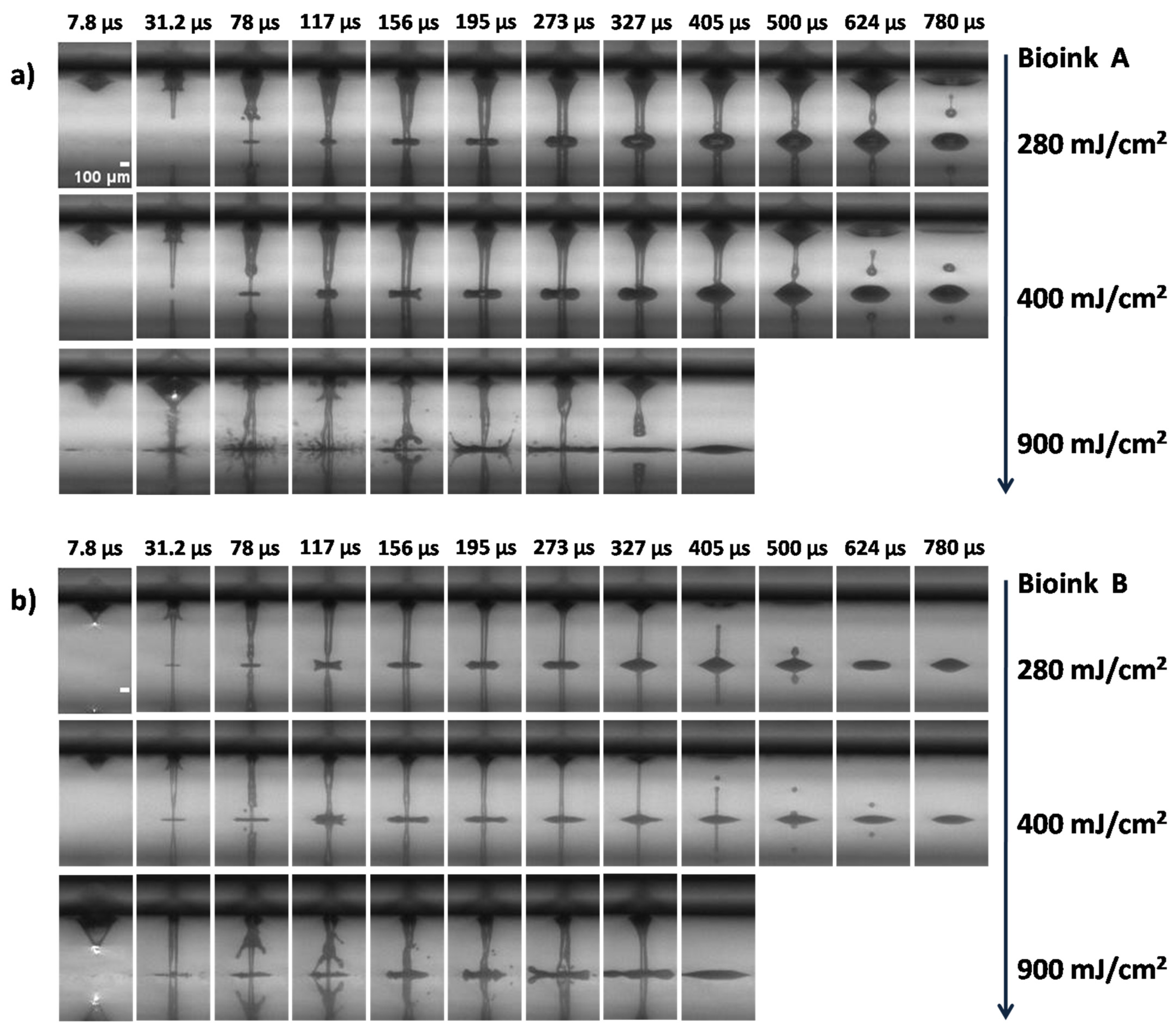
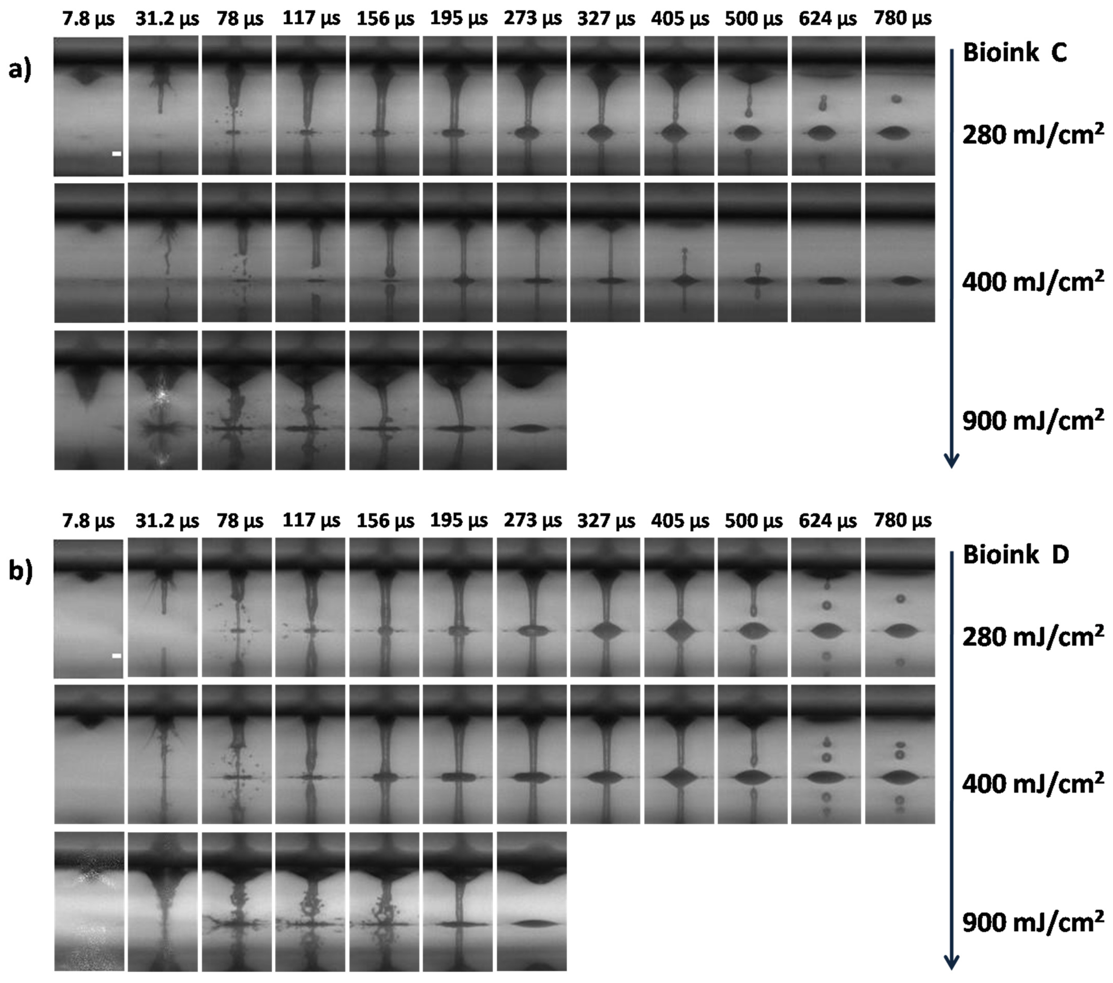
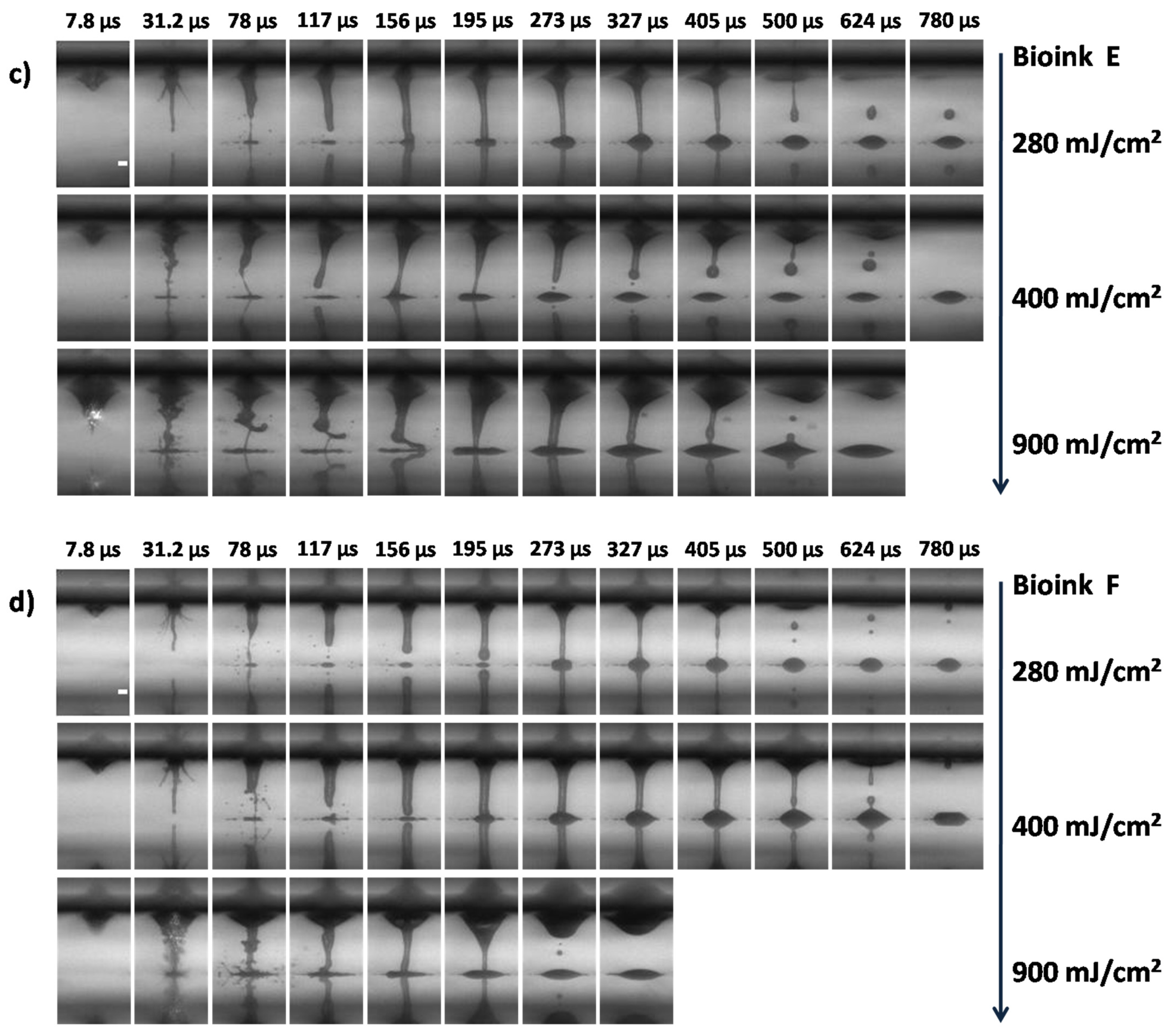
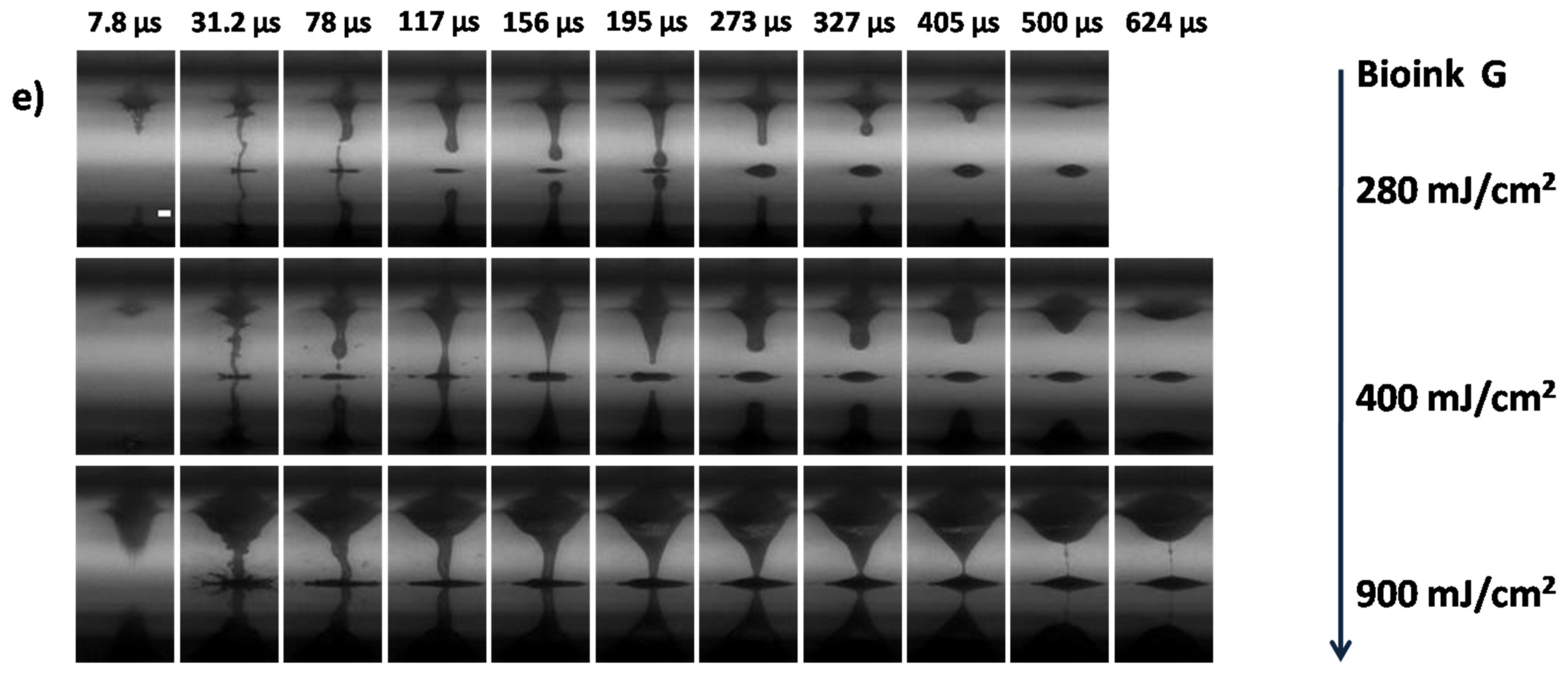
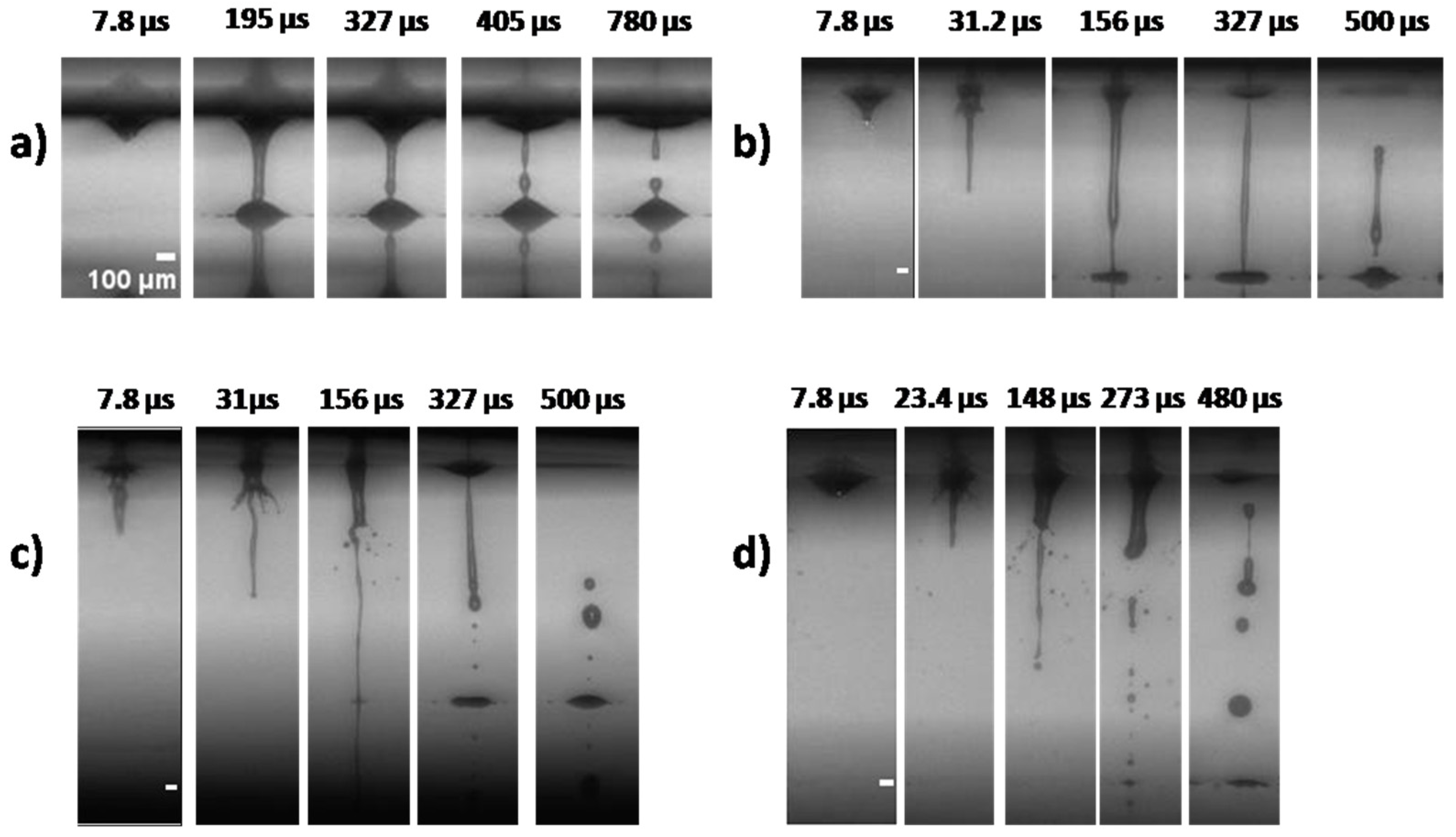
3.2. Jet Formation and Breakup during LIFT Printing
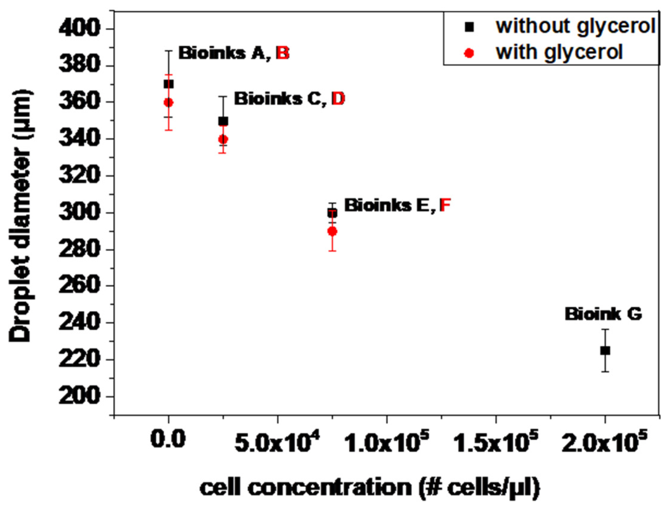
3.3. Effect of Cell-Laden Bioink (and Cell-Free Bioink) Concentration on Printed Droplet Size
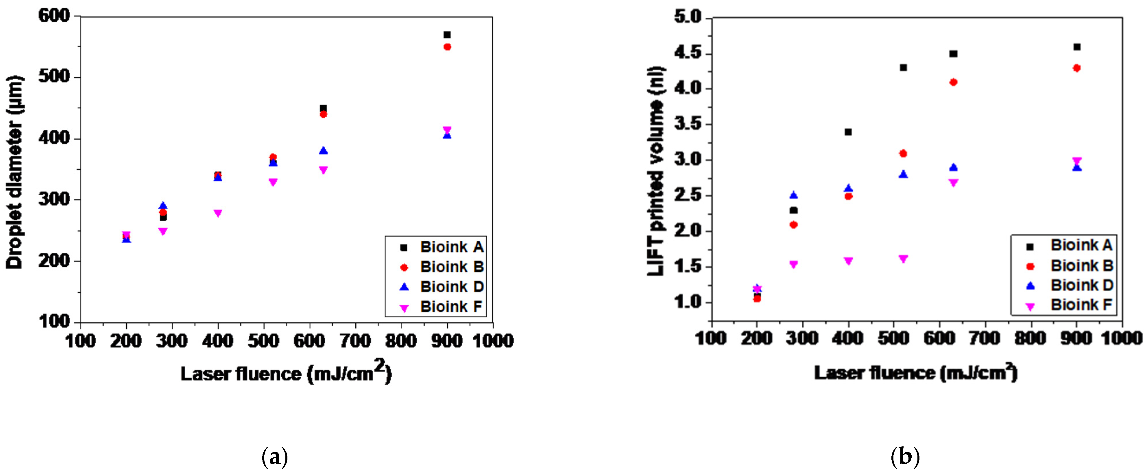
3.4. Influence of Laser Fluence on the Printed Volume and Droplet Size
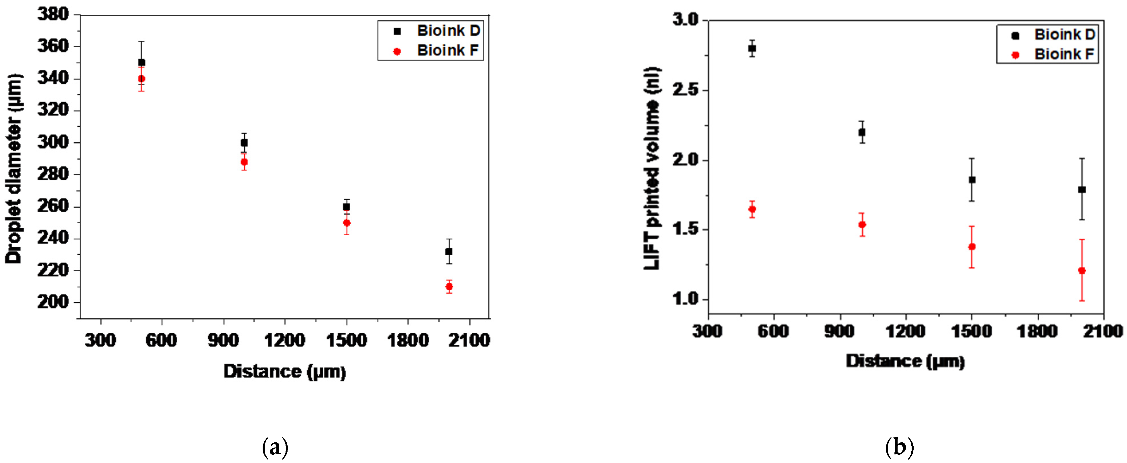
3.5. Influence of Distance between Donor and Receiver Substrate on the Jet Development and The Morphology of the Printed Droplets
4. Conclusions
Author Contributions
Funding
Data Availability Statement
Acknowledgments
Conflicts of Interest
References
- Ringeisen, B.R.; Pirlo, R.K.; Wu, P.K.; Boland, T.; Huang, Y.; Sun, W.; Hamid, Q.; Chrisey, D.B. Cell and organ printing turns 15: Diverse research to commercial transitions. MRS Bull. 2013, 38, 834–843. [Google Scholar] [CrossRef]
- Nakamura, M.; Iwanaga, S.; Henmi, C.; Arai, K.; Nishiyama, Y. Biomatrices and biomaterials for future developments of bioprinting and biofabrication. Biofabrication 2010, 2, 014110. [Google Scholar] [CrossRef] [PubMed]
- Lee, H.; Young, W.K.; Miji, Y.; Kim, S.H.; Kim, G.H. Recent cell printing systems for tissue engineering. Int. J. Bioprinting 2017, 3, 27–41. [Google Scholar] [CrossRef] [PubMed]
- Christensen, K.; Xu, C.; Chai, W.; Zhang, Z.; Fu, J.; Huang, Y. Freeform inkjet printing of cellular structures with bifurcations. Biotechnol. Bioeng. 2015, 112, 1047–1055. [Google Scholar] [CrossRef]
- Kryou, C.; Leva, V.; Chatzipetrou, M.; Zergioti, I. Bioprinting for Liver Transplantation. Bioengineering 2019, 6, 95. [Google Scholar] [CrossRef] [PubMed] [Green Version]
- Karaiskou, A.; Zergioti, I.; Fotakis, C.; Kapsetaki, M.; Kafetzopoulos, D. Microfabrication of biomaterials by the sub-ps laser-induced forward transfer process. Appl. Surf. Sci. 2003, 208, 245–249. [Google Scholar] [CrossRef]
- Zhang, X.; Zhang, Y. Tissue engineering applications of three-dimensional bioprinting. Cell Biochem. Biophys. 2015, 72, 777–782. [Google Scholar] [CrossRef]
- Adrian, F.; Bohandy, J.; Kim, B.; Jette, A.N.; Thompson, P. A study of the mechanism of metal deposition by the laser-induced forward transfer process. J. Vac. Sci. Technol. B 1987, 5, 1490–1494. [Google Scholar] [CrossRef]
- Hopp, B.; Smausz, T.; Antal, Z.; Kresz, N.; Bor, Z.; Chrisey, D. Absorbing film assisted laser induced forward transfer of fungi (Trichoderma conidia). J. Appl. Phys. 2004, 96, 3478–3481. [Google Scholar] [CrossRef]
- Hopp, B.; Smausz, T.; Kresz, N.; Barna, N.; Bor, Z.; Kolozsvári, L.; Chrisey, D.B.; Szabó, A.; Nógrádi, A. Survival and proliferative ability of various living cell types after laser-induced forward transfer. Tissue Eng. 2005, 11, 1817–1823. [Google Scholar] [CrossRef]
- Colina, M.; Serra, P.; Fernández-Pradas, J.M.; Sevilla, L.; Morenza, J.L. Dna deposition through laser induced forward transfer. Biosens. Bioelectron. 2005, 20, 1638–1642. [Google Scholar] [CrossRef]
- Yamada, H.; Sano, T.; Nakayama, T.; Miyamoto, I. Optimization of laser-induced forward transfer process of metal thin films. Appl. Surf. Sci. 2002, 197, 411–415. [Google Scholar] [CrossRef]
- Banks, D.P.; Grivas, C.; Mills, J.D.; Eason, R.W.; Zergioti, I. Nano-droplets deposited in microarrays by femtosecond ti: Sapphire laser-induced forward transfer. Appl. Phys. Lett. 2006, 89, 193107. [Google Scholar] [CrossRef] [Green Version]
- Tsouti, V.; Filippidou, M.K.; Boutopoulos, C.; Broutas, P.; Zergioti, I.; Chatzandroulis, S. Self-aligned process for the development of surface stress capacitive biosensor arrays. Sens. Actuators B Chem. 2012, 166–167, 815–818. [Google Scholar] [CrossRef]
- Chrisey, D.B.; Piqué, A.; McGill, R.A.; Horwitz, J.S.; Ringeisen, B.R.; Bubb, D.M.; Wu, P.K. Laser deposition of polymer and biomaterial films. Chem. Rev. 2003, 103, 553–576. [Google Scholar] [CrossRef] [PubMed]
- Dinca, V.; Ranella, A.; Popescu, A.; Dinescu, M.; Farsar, I.M.; Fotakis, C. Parameters optimization for biological molecules patterning using 248-nm ultrafast lasers. Appl. Surf. Sci. 2007, 254, 1164–1168. [Google Scholar] [CrossRef]
- Brasz, C.F.; Arnold, C.B.; Stone, H.A.; Lister, J.R. Early-time free-surface flow driven by a deforming boundary. J. Fluid Mech. 2015, 767, 811–841. [Google Scholar] [CrossRef]
- Dinca, V.; Farsari, M.; Kafetzopoulos, D.; Popescu, A.; Dinescu, M.; Fotakis, C. Patterning parameters for biomolecules microarrays constructed with nanosecond and femtosecond UV lasers. Thin Solid Films 2008, 516, 6504. [Google Scholar] [CrossRef]
- Zergioti, I.; Papazoglou, D.G.; Karaiskou, A.; Fotakis, C.; Kapsetaki, E.; Kafetzopoulos, D. Femtosecond Laser Microprinting of Biomaterials. Appl. Physs. Lett. 2005, 86, 163902. [Google Scholar] [CrossRef] [Green Version]
- Leva, V.; Chatzipetrou, M.; Alexopoulos, L.; Tzeranis, D.S.; Zergioti, I. Direct laser printing of liver cells on porous collagen scaffold. J. Laser Micro Nanoeng. 2018, 18, 104. [Google Scholar]
- Zhang, Z.; Xu, C.; Xiong, R.; Chrisey, D.B.; Huang, Y. Effects of living cells on the bioink printability during laser printing. Biomicrofluidics 2017, 11, 034120. [Google Scholar] [CrossRef]
- Michael, S.; Sorg, H.; Peck, C.T.; Koch, L.; Deiwick, A.; Chichkov, B.; Vogt, P.M.; Reimers, K. Tissue Engineered Skin Substitutes Created by Laser-Assisted Bioprinting Form Skin-Like Structures in the Dorsal Skin Fold Chamber in Mice. PLoS ONE 2013, 8, e57741. [Google Scholar] [CrossRef] [PubMed]
- Wu, P.K.; Ringeisen, B.R. Development of Human Umbilical Vein Endothelial Cell (HUVEC) and Human Umbilical Vein Smooth Muscle Cell (HUVSMC) Branch/Stem Structures on Hydrogel Layers Via Biological Laser Printing (BioLP). Biofabrication 2010, 2, 014111. [Google Scholar] [CrossRef]
- Phamduy, T.B.; Raof, N.A.; Schiele, N.R.; Yan, Z.; Corr, D.T.; Huang, Y.; Xie, Y.; Chrisey, D.B. Laser direct-write of single microbeads into spatially-ordered patterns. Biofabrication 2012, 4, 025006. [Google Scholar] [CrossRef] [Green Version]
- Ouyang, L.; Yao, R.; Chen, X.; Na, J.; Sun, W. 3D Printing of HEK 293FT Cell-Laden Hydrogel into Macroporous Constructs with High Cell Viability and Normal Biological Functions. Biofabrication 2015, 7, 015010. [Google Scholar] [CrossRef]
- Turkoz, E.; Fardel, R.; Arnold, C.B. Advances in Blister-Actuated Laser Induced Forward Transfer (BA-LIFT)—Chap. 1. Laser Print. Funct. Mater. 3D Microfabr. Electron. Biomed. 2017, 8, 2. [Google Scholar]
- Murphy, S.V.; Atala, A. 3D bioprinting of tissues and organs. Nat. Biotechnol. 2014, 32, 773–785. [Google Scholar] [CrossRef]
- Guillemot, F.; Souquet, A.; Catros, S.; Guillotin, B. Laser-assisted cell printing: Principle, physical parameters versus cell fate and perspectives in tissue engineering. Nanomedicine 2010, 5, 507–515. [Google Scholar] [CrossRef] [PubMed]
- Barron, J.A.; Young, H.D.; Dlott, D.D.; Darfler, M.M.; Krizman, D.B.; Ringeisen, B.R. Printing of protein microarrays via a capillary-free fluid jetting mechanism. Proteomics 2005, 5, 4138. [Google Scholar] [CrossRef]
- Duocastella, M.; Fernández-Pradas, J.M.; Morenza, J.L.; Serra, P. Study of the laser-induced forward transfer of liquids for laser bioprinting. Appl. Surf. Sci. 2007, 253, 5789–7855. [Google Scholar] [CrossRef]
- Colina, M.; Duocastella, M.; Fernández-Pradas, J.M.; Serra, P.; Morenza, J.L. Laser-induced forward transfer of liquids: Study of the droplet ejection process. J. Appl. Phys. 2006, 99, 084909/1–084909/7. [Google Scholar] [CrossRef] [Green Version]
- Guillotin, B.; Souquet, A.; Catros, S.; Duocastella, M.; Pippenger, B.; Bellance, S.; Bareille, R.; Rémy, M.; Bordenave, L.; Amédée, J.; et al. Laser assisted bioprinting of engineered tissue with high cell density and microscale organization. Biomaterials 2010, 28, 7250–7256. [Google Scholar] [CrossRef] [PubMed]
- Riester, D.; Budde, J.; Gach, C.; Gillner, A.; Wehner, M. High Speed Photography of Laser Induced Forward Transfer (LIFT) of Single and Double-layered Transfer Layers for Single Cell Transfer. J. Laser Micro Nanoeng. 2016, 11, 199–203. [Google Scholar] [CrossRef] [Green Version]
- Wang, W.; Huang, Y.; Grujicic, M.; Chrisey, D.B. Study of impact-induced mechanical effects in cell direct writing using smooth particle hydrodynamic method. J. Manuf. Sci. Eng. 2008, 130, 02101210. [Google Scholar] [CrossRef]
- Palla-Papavlu, A.; Dinca, V.; Luculescu, C.; Shaw-Stewart, J.; Nagel, M.; Lippert, T.; Dinescu, M. Laser induced forward transfer of soft materials. J. Opt. 2010, 12, 124014. [Google Scholar] [CrossRef]
- Catros, S.; Guillotin, B.; Bacáková, M.; Fricain, J.C.; Guillemot, F. Effect of laser energy, substrate film thickness and bioink viscosity on viability of endothelial cells printed by laser-assisted bioprinting. Appl. Surf. Sci. 2011, 257, 5142–5144. [Google Scholar] [CrossRef]
- Kantardjieff, A.; Zhou, W. Mammalian cell cultures for biologics manufacturing. Adv. Biochem. Eng. Biotechnol. 2014, 139, 1–9. [Google Scholar]
- Kattamis, N.T.; Purnick, P.E.; Weiss, R.; Arnold, C.B. Thick film laser induced forward transfer for deposition of thermally and mechanically sensitive materials. Appl. Phys. Lett. 2007, 91, 171120. [Google Scholar] [CrossRef] [Green Version]
- Guillemot, F.; Souquet, A.; Catros, S.; Guillotin, B.; Lopez, J.; Faucon, M.; Pippenger, B.; Bareille, R.; Rémy, M.; Bellance, S.; et al. High-throughput laser printing of cells and biomaterials for tissue engineering. Acta Biomater. 2010, 6, 2494–2500. [Google Scholar] [CrossRef]
- Desrus, H.; Chassagnea, B.; Catros, S.; Artiges, C.; Devillard, R.; Petit, S.; Deloison, F.; Fricain, J.C.; Guillemot, F.; Kling, R. Laser assisted bioprinting using a femtosecond laser with and without a gold transductive layer: A parametric study. In Optical Interactions with Tissue and Cells XXVII; International Society for Optics and Photonics: Bellingham, WA, USA, 2016; Volume 9706, p. 97060O. [Google Scholar]
- Duocastella, M.; Patrascioiu, A.; Dinca, V.; Fernández-Pradas, J.M.; Morenza, J.L.; Serra, P. Study of liquid deposition during laser printing of liquids. Appl. Surf. Sci. 2011, 257, 5255–5258. [Google Scholar] [CrossRef]
- Duocastella, M.; Fernández-Pradas, J.M.; Serra, P.; Morenza, J.L. Time-resolved imaging of the laser forward transfer of liquids. J. Appl. Phys. 2009, 106, 084907. [Google Scholar] [CrossRef] [Green Version]
- Lin, Y.; Huang, Y.; Chrisey, D.B. Metallic Foil-Assisted Laser Cell Printing. J. Biomech. Eng. 2011, 133, 025001. [Google Scholar] [CrossRef]
- Kuznetsov, A.I.; Unger, C.; Koch, J.; Chichkov, B.N. Laser-induced jet formation and droplet ejection from thin metal films. Appl. Phys. A 2012, 106, 479–487. [Google Scholar] [CrossRef]
- Dinca, V.; Patrascioiu, A.; Fernández-Pradas, J.M.; Morenza, J.L.; Serra, P. Influence of solution properties in the laser forward transfer of liquids. Appl. Surf. Sci. 2012, 258, 9379–9384. [Google Scholar] [CrossRef]
- Souquet, A. 2011 Study of the Physical Processes Involved in the Microprinting of Biological Elements Assisted by Laser. Ph.D. Thesis, University of Bordeaux 1, Bordeaux, France, 2011. [Google Scholar]
- Duocastella, M.; Fernández-Pradas, J.M.; Serra, P.; Morenza, J.L. Sessile droplet formation in the laser-induced forward transfer of liquids: A time-resolved imaging study. Thin Solid Films 2010, 518, 5321–5325. [Google Scholar] [CrossRef]
- Fernández-Pradas, J.M.; Florian, C.; Caballero-Lucas, F.; Sopeña, P.; Morenza, J.L.; Serra, P. Laser-induced forward transfer: Propelling liquids with light. Appl. Surf. Sci. 2017, 418, 559–564. [Google Scholar] [CrossRef]
- Boutopoulos, C.; Kalpyris, I.; Serpetzoglou, E.; Zergioti, I. Laser-induced forward transfer of silver nanoparticle ink: Time-resolved imaging of the jetting dynamics and correlation with the printing quality. Microfluid. Nanofluid. 2014, 16, 493. [Google Scholar] [CrossRef]
- Zhang, Z.; Xiong, R.; Mei, R.; Huang, Y.; Chrisey, D.B. Time-Resolved Imaging Study of Jetting Dynamics during Laser Printing of Viscoelastic Alginate Solutions. Langmuir 2015, 31, 6447–6456. [Google Scholar] [CrossRef]
- Zhang, Z.; Xiong, R.; Corr, D.T.; Huang, Y. Study of Impingement Types and Printing Quality during Laser Printing of Viscoelastic Alginate Solutions. Langmuir 2016, 32, 3004–3014. [Google Scholar] [CrossRef]
- Yu, J.; Sakai, S.; Sethian, J.A. Two-Phase Viscoelastic Jetting. J. Comput. Phys. 2007, 220, 568–585. [Google Scholar] [CrossRef] [Green Version]
- Dong, H.; Carr, W.W.; Morris, J.F. An Experimental Study of Drop-on-Demand Drop Formation. Phys. Fluids 2006, 18, 072102. [Google Scholar] [CrossRef]
- Zhang, Z. Study of Printing Mechanism and Printing-Induced Cell Injury during Laser Printing. Ph.D. Thesis, University of Florida, Gainesville, FL, USA, August 2016. [Google Scholar]
- Koch, L.; Brandt, O.; Deiwick, A.; Chichkov, B. Laser-assisted Bioprinting at Different Wavelengths and Pulse Durations with a Metal Dynamic Release Layer: A Parametric Study. Int. J. Bioprinting 2017, 3, 42–53. [Google Scholar] [CrossRef] [PubMed] [Green Version]
- Unger, C.; Gruene, M.; Koch, L.; Chichkov, B. Time-resolved Imaging of Hydrogel Printing via Laser-induced Forward Transfer. Appl. Phys. A Mater. Sci. Process 2011, 103, 271–277. [Google Scholar] [CrossRef]
- Deng, Y.; Renaud, P.; Guo, Z.; Huang, Z.; Chen, Y. Single cell isolation process with laser induced forward transfer. J. Biol. Eng. 2017, 11, 2. [Google Scholar] [CrossRef] [PubMed] [Green Version]
- Duocastella, M.; Fernandez-Pradas, J.M.; Morenza, J.L.; Serra, P. Droplet Printing through Bubble Contact in the Laser Forward Transfer of Liquids. Appl. Surf. Sci. 2011, 257, 2825–2829. [Google Scholar] [CrossRef]


| Bioink | Composition | Viscosity (mPa.s) | Density (g/cm3) |
|---|---|---|---|
| A | Dulbecco’s Modified Eagle’s Medium (DMEM) | 2.1755 | 1.0092 |
| B | Dulbecco’s Modified Eagle’s Medium (DMEM) (+10% glycerol) | 2.3767 | 1.0360 |
| C | DMEM + MDA-MB-468 (2.5 × 10⁴ cells/μL) | - | - |
| D | DMEM (+10% glycerol) + MDA-MB-468 (2.5 × 10⁴ cells/μL + 10% glycerol) | - | - |
| E | DMEM + MDA-MB-468 (7.5 × 10⁴ cells/μL) | - | - |
| F | DMEM (+10% glycerol) + MDA-MB-468 (7.5 × 10⁴ cells/μL + 10% glycerol) | - | - |
| G | DMEM + MDA-MB-468 (20 × 104 cells/μL) | - | - |
| Bioink | Printed Cells | Dead Cells |
|---|---|---|
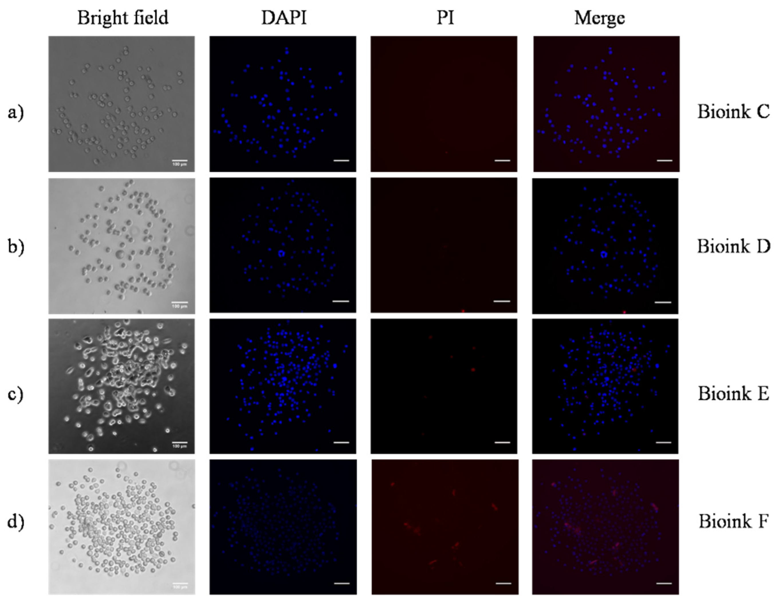
| C | 121 ± 9 | 7 ± 2 |
| D | 110 ± 4 | 11 ± 5 |
| E | 180 ± 16 | 9 ± 5 |
| F | 185 ± 14 | 12 ± 7 |
| Laser Fluence (mJ/cm2) | Bioink | Printed Cells | Dead Cells |
|---|---|---|---|
| 400 | Bioink C Bioink D Bioink E Bioink F | 65 ± 5 90 ± 6 163 ± 10 160 ± 12 | 0 4 ± 3 7 ± 6 15 ± 9 |
| 900 | Bioink C Bioink D Bioink E Bioink F | 83 ± 7 104 ± 10 240 ± 14 260 ± 20 | 12 ± 5 8 ± 6 35 ± 6 25 ± 9 |
Publisher’s Note: MDPI stays neutral with regard to jurisdictional claims in published maps and institutional affiliations. |
© 2021 by the authors. Licensee MDPI, Basel, Switzerland. This article is an open access article distributed under the terms and conditions of the Creative Commons Attribution (CC BY) license (https://creativecommons.org/licenses/by/4.0/).
Share and Cite
Kryou, C.; Theodorakos, I.; Karakaidos, P.; Klinakis, A.; Hatziapostolou, A.; Zergioti, I. Parametric Study of Jet/Droplet Formation Process during LIFT Printing of Living Cell-Laden Bioink. Micromachines 2021, 12, 1408. https://0-doi-org.brum.beds.ac.uk/10.3390/mi12111408
Kryou C, Theodorakos I, Karakaidos P, Klinakis A, Hatziapostolou A, Zergioti I. Parametric Study of Jet/Droplet Formation Process during LIFT Printing of Living Cell-Laden Bioink. Micromachines. 2021; 12(11):1408. https://0-doi-org.brum.beds.ac.uk/10.3390/mi12111408
Chicago/Turabian StyleKryou, Christina, Ioannis Theodorakos, Panagiotis Karakaidos, Apostolos Klinakis, Antonios Hatziapostolou, and Ioanna Zergioti. 2021. "Parametric Study of Jet/Droplet Formation Process during LIFT Printing of Living Cell-Laden Bioink" Micromachines 12, no. 11: 1408. https://0-doi-org.brum.beds.ac.uk/10.3390/mi12111408