
Effects of Structural Dimension Variation on the Vibration of MEMS Ring-Based Gyroscopes
by
 , , and
Zhipeng Ma
1,2 ,
,
Xiaoli Chen
1,2,
Xiaojun Jin
1,2,*,
Yiming Jin
1,2,
Xudong Zheng
1,2 and
Zhonghe Jin
1,2 1
Micro-Satellite Research Center, Zhejiang University, Hangzhou 310007, China
2
Key Laboratory of Micro/Nano-Satellite Research, Hangzhou 310007, China
*
Author to whom correspondence should be addressed.
Micromachines 2021, 12(12), 1483; https://0-doi-org.brum.beds.ac.uk/10.3390/mi12121483
Submission received: 5 November 2021
/
Revised: 26 November 2021
/
Accepted: 27 November 2021
/
Published: 29 November 2021
(This article belongs to the Special Issue Micro Inertial Sensors: Calibration Methods, Technologies and Application)
Abstract
:This study investigated the effects of structural dimension variation arising from fabrication imperfections or active structural design on the vibration characteristics of a (100) single crystal silicon (SCS) ring-based Coriolis vibratory gyroscope. A mathematical model considering the geometrical irregularities and the anisotropy of Young’s modulus was developed via Lagrange’s equations for simulating the dynamical behavior of an imperfect ring-based gyroscope. The dynamical analyses are focused on the effects on the frequency split between two vibration modes of interest as well as the rotation of the principal axis of the 2θ mode pair, leading to modal coupling and the degradation of gyroscopic sensitivity. While both anisotropic Young’s modulus and nonideal deep trench verticality affect the frequency difference between two vibration modes, they have little contribution to deflecting the principal axis of the 2θ mode pair. However, the 4θ variations in the width of both the ring and the supporting beams cause modal coupling to occur and the degenerate 2θ mode pair to split in frequency. To aid the optimal design of MEMS ring-based gyroscopic sensors that has relatively high robustness to fabrication tolerance, a geometrical compensation based on the developed model is demonstrated to identify the geometries of the ring and the suspension.
1. Introduction
Ring-based gyroscopic sensors based on micro-electro-mechanical-system (MEMS) technology become increasingly attractive because of their high-quality factor (Q factor) and insensitivity to environmental excitation as a result of inherently symmetric structures [1,2,3]. Degenerate modes of vibratory axisymmetric ring-based structures are exploited to measure the angular rate through Coriolis coupling. When applied to external rotations about the normal axis of the ring resonator, the energy transfer occurs between the degenerate modes as a result of the Coriolis coupling effect. For a ring-based angular-rate gyroscope, one of the degenerate modes is excited with controlled amplitude and frequency, while the Coriolis force-induced vibration of the other mode is utilized to measure the angular-rate input through capacitive sensing. The ideal ring-based structures are preferred since their degenerate modes have the same resonant frequencies dictating extremely high-scale factor of the ring-based gyroscopes operating with a high Q factor [4]. The ring-based gyroscopes fabricated with isotropic materials, such as polysilicon, (111) SCS, and fused silica, are advantageous to realize mode-matching between two degenerate modes. However, the ring-based gyroscopes of isotropic materials require a more complicated and precise fabrication process than those fabricated with (100) SCS. On the other hand, the ring-based gyroscopes fabricated with (100) SCS frequently suffer from a large initial frequency split and modal coupling arising from the anisotropic Young’s modulus and the fabrication imperfections. In order to improve the dynamic performance of the imperfect ring-based gyroscopes, the post-fabrication trimming or electrostatic tuning techniques are frequently utilized for the compensation of the initial frequency split and modal coupling [5,6]. However, these techniques are sometimes not preferred due to less fidelity and efficiency. To evaluate the effects of the material anisotropy as well as the structural dimension variation, a detailed mathematical model of an imperfect ring resonator is required.
Previous works have analyzed the effects of the anisotropy of Young’ modulus on the frequency split of ring-based resonators and gyroscopes based on various numerical models utilizing the finite element method (FEM) [7,8] and analytical models [9,10], as demonstrated in Table 1. The effects of anisotropy of crystalline silicon on the vibration characteristics of ring-based resonators were accounted for in the strain energy formulation by S. McWilliam et al. [9], allowing analytical expression of the frequency split in terms of a Fourier representation of the variation in the elastic properties [7,10]. The structural imperfection of the ring-based resonators is commonly modeled as small attached masses and springs [11,12,13], which facilitate the mass trimming [14] or electrostatic tuning [6] for the reduction in frequency split. To mitigate the initial frequency split caused by the anisotropic Young’s modulus, active compensation methods based on the variation of the geometries of the ring and the suspension were proposed and proven to work effectively to some extent [7,15,16]. As can be seen, a detailed analytical model taking into account the material and structural asymmetries is still required for the development of high-performance ring-based rate or rate-integrating gyroscopes, in which circumferential uniformity and mode-matching are crucial prerequisites [17,18].
In this paper, we present a mathematical model of an imperfect ring-based gyroscope that can be utilized for the assessment of the vibration characteristics of the ring-based gyroscopes when considering the structural and material variations as illustrated in Table 1. The proposed model allows quantification of the effects of structural dimension variations and optimizing the geometrical design canceling out the effect of anisotropic Young’s modulus. Furthermore, in order to simplify the problem, we modeled both the anisotropy of Young’s modulus and the ring-based structural dimension variation in a 4θ periodic manner, which dominates the frequency split and modal coupling between the 2θ vibration modes of interest [10]. Moreover, the undesired material nonlinearity and the residue stress are not considered in this model. Based on the developed model, the effects of structural dimension variations were fully investigated and the optimized geometry that has the robustness to fabrication imperfection was proposed.
2. Mathematical Modeling
The ring-based Coriolis vibratory gyroscopes exploit the degenerate mode pairs of a resonator consisting of a ring, a mechanical suspension, an anchor, and a series of electrodes. A perfect ring can be regarded as a curved, continuous elastic beam whose resonance can be analyzed with the normal mode method [10]. Since the ring-based gyroscopes are usually designed and fabricated with a high aspect ratio, their out-of-plane resonances are inherently suppressed, ensuring that the simple assumption of in-plane vibration modes is still valid [19]. The in-plane resonance modes are described as nθ mode pairs, each pair of which is degenerate with identical natural frequencies for a perfect ring structure. In contrast, an imperfect ring will exhibit distinct but close natural frequencies for each nθ mode pair. The mechanical and electrostatic nonlinearity that enlarge the frequency split as the vibration amplitude increases [20,21,22] are not considered in this paper for simplicity.
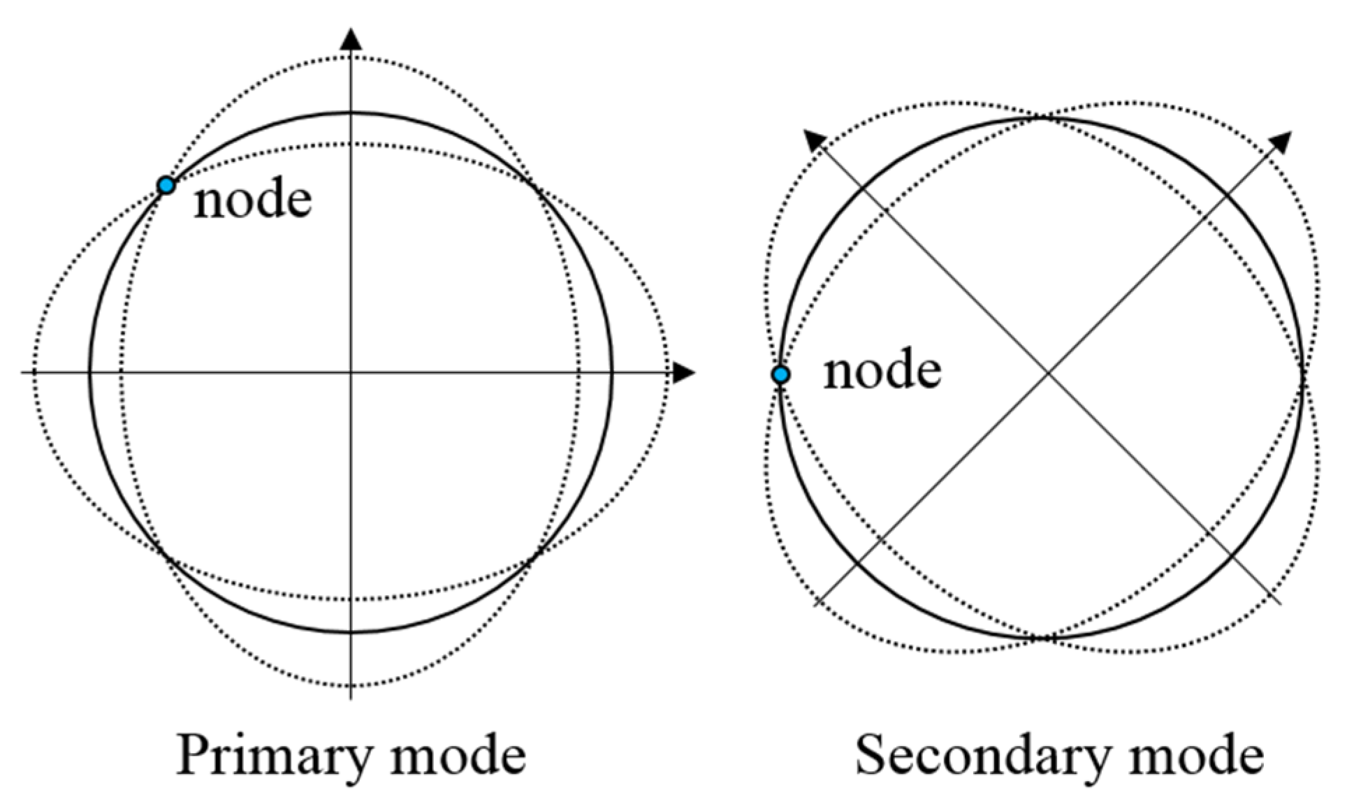
The resulting displacement of a ring resonator can be expressed as a weighted sum of the in-plane modes with generalized coordinates. Herein, we only consider the degenerate 2θ modes as shown in Figure 1, which are mostly utilized as the drive and sense modes of vibratory ring-based gyroscopes [1,3]. As a result, the displacement of the ring resonator is represented as Equation (1), where ur and ut are the radial and tangential displacement of the ring resonator, respectively, and ux and uy are the cartesian components of the displacement, respectively. Values q1 and q2 are the generalized modal coordinates.
The radial (φr1, φr2) and tangential (φt1, φt2) components of the 2θ mode shapes are expressed as:
where θ0 is the principal axis of one vibration mode of the 2θ mode pair, and that of the other mode is oriented 45° away from θ0; θ is the angular position of the ring resonator.
The cartesian components of the 2θ mode shapes are given by:
2.1. Structural Imperfection Consideration
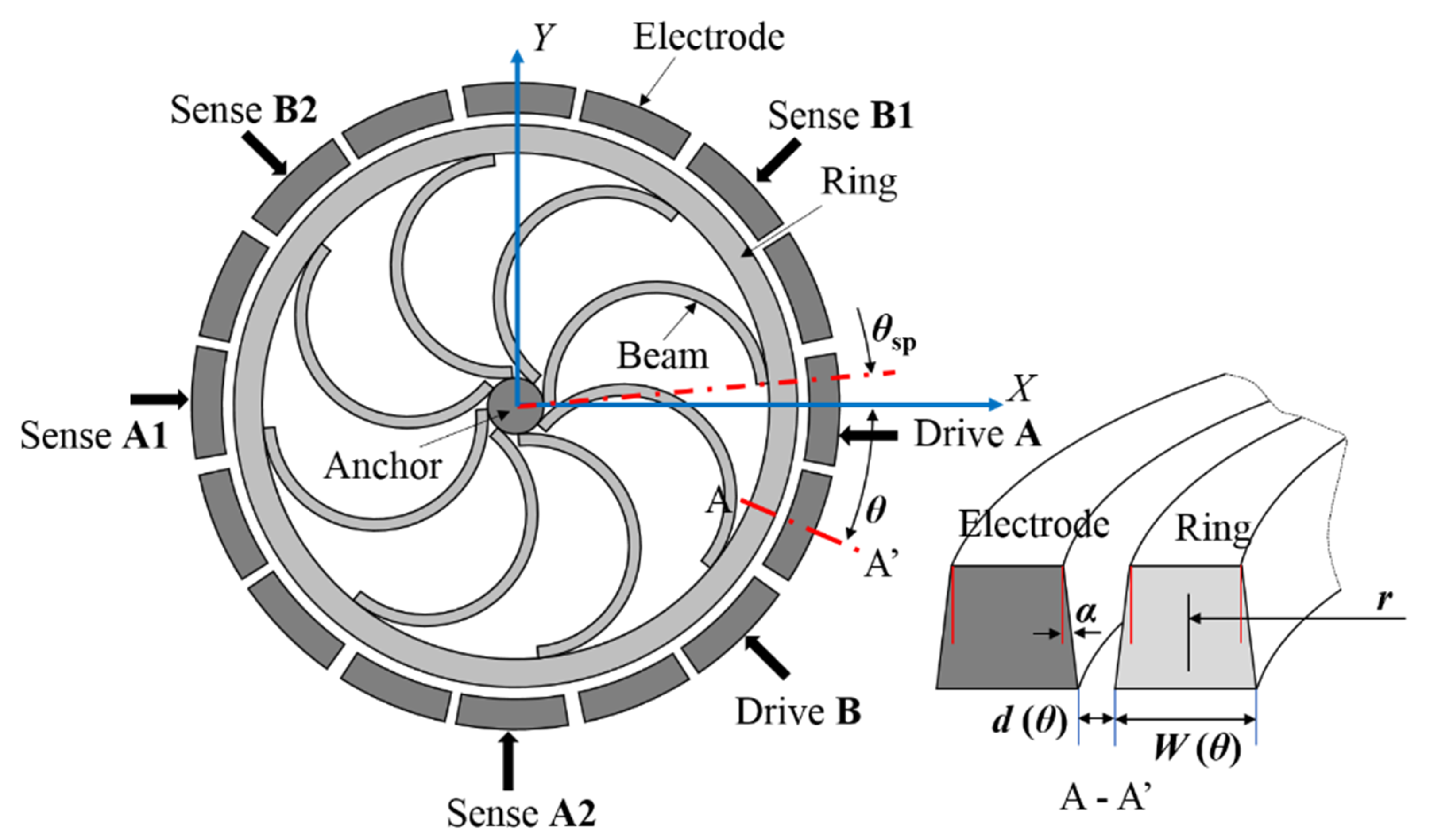
The presence of material anisotropy and fabrication imperfection, which cannot be completely avoided, severely reduces the degeneracy and the sensitivity of ring-based gyroscopes [8]. As a result, the frequency between the drive and sense modes splits and their principal axes deflects from the predefined orientation as a result of the mass and stiffness asymmetries. This paper considers the anisotropic Young’s modulus of (100) SCS and the geometrical irregularities existed in the fabricated vibratory ring gyroscopes. As illustrated in Figure 2, the imperfect ring structure is suspended to an anchor by a mechanical suspension, composed of eight flexible semi-circular beams. The width of the ring structure varies in both circumferential and vertical directions. The sixteen surrounding electrodes are deployed for capacitive actuation, sensing, and tuning. The X and Y axes correspond to the <110> crystal directions, while the axes at 45°, 135°, 225°, and 315° are aligned to the <100> crystal direction. The ring resonator is excited by the capacitive electrode at 0° (Drive A) and the capacitive electrode at 315° (Drive B), and sensed by a differential configuration (Sense A1 and A2, Sense B1 and B2) for two vibration modes.
The Young’s modulus of the (100) SCS ring can be represented as Fourier series expansions in terms of θ, whose 4θ component is proven to dominate the frequency split between two vibration modes [10], given by:
where E0, δE4 are the average and 4θ variation component of the Young’s modulus, respectively, eE is the variation coefficient of the Young’s modulus, and θE4 is the orientation of the modulus variation with respect to the X-axis.
It is assumed that the deep trench is etched with an inclination α and the average ring width also varies circumferentially in a 4θ variation manner. The variation of the ring width and the capacitive gap between the ring and the surrounding electrodes are expressed as:
where h and Wr are the thickness and the average radial width of the ring, respectively; w and θw are the variation of the ring width and the variation orientation with respect to X-axis, respectively.
The supporting beams of the ring-based gyroscopes are frequently modeled as uniform elastic springs [10,19]. The influence of anisotropic Young’s modulus on the supporting semicircular beams is confirmed to be ineligible by modal analysis using the finite element method (FEM). As a result, we considered the irregularity of the fabricated supporting beams to be the variation of the beam width as well as the variation of the supporting location. Since the supporting beams are distributed with a pitch of 45°, they can be divided into two orthogonal groups, each of which have four beams with a pitch of 90°. One beam group has the uniform yet different beam widths with the other beam group. All supporting beams are oriented θsp away from the corresponding electrodes. The beam width of two beam groups is shown as:
where Wsp0 and wsp are the average beam width and the variation of beam width between two beam groups, respectively.
2.2. Energies of Ring-Based Gyroscope
Lagrange’s equation can be used to derive the equations of motion for the ring-based gyroscopes [10,19]. Lagrange’s equation is based on the energies of the gyroscope system including the kinetic energy of the ring, the strain energy of the ring, the potential energy of the supporting springs, the electrostatic potential energy, and the damping dissipation.
The kinetic energy of the ring is derived from:
where ρ is the density of the ring material, V is the volume of the ring, and ΩZ is the angular rate about the axis of the ring.
The kinetic energy of the ring is obtained by substituting Equation (1) into (8):
where A is the area of the cross-section of the ring, and,
Taking into account of the asymmetries of the ring, the mass Mij in Equation (10) becomes:
The modal coupling in terms of inertia can be neglected since the variation of the ring width is negligibly small when compared to the ring width itself. Therefore, M12 and M21 are considered to be zero in the following discussions. Similarly, the in-plane displacement of the ring is negligibly small when compared to the radial thickness. As a result, the ring structure can be considered to be inextensible and linear, ensuring that the bending strain energy is dominant [19].
The change in curvature of each ring element due to bending can be expressed as:
As a result, the bending strain energy of the entire ring structure is obtained by integrating the bending energy over the ring elements, given by:
where E is the Young’s modulus and I = w3t / 12 is the second moment of area. Replacing the change in curvature of each ring element in Equation (14), the bending energy can be shown as:
where Krij represents the mechanical stiffness of the ring structure, given by:
For simplicity, each semicircular supporting beam is modeled by incorporating one radial and one tangential spring to the ring structure. Based on static equilibrium analysis, the radial stiffness (Kbr) and the tangential stiffness (Kbt) of the semicircular beam are given by [10]:
The potential energy of the support springs can be derived by summing the potential energies of eight beams, given by:
Replacing the displacement of the ring at the positions where the supporting springs are attached in Equation (1), it can be shown as:
where Kspij (i, j =1, 2) represents the effective stiffness of the supporting springs by the expression:
The capacitive electrodes for the drive and sense of the ring gyroscope are shown in Figure 2. Considering the imperfections of the ring and the capacitive gap, the capacitors cannot be simply approximated as parallel plate capacitors. For a non-parallel plate capacitor, the capacitance for an electrode pair at θn is given by:
where Δd represents the radial displacement of the ring element.
By integrating Equation (23) along h, the capacitance is expressed as:
To facilitate the development of linear analytical expression that takes into account of all the structural imperfections, the integrated term in Equation (24) is approximated by the linear terms of its Taylor series expansion:
The full expression of each component in Equation (25) is shown in Appendix A. The total electrostatic potential energies arising from the drive and sense electrodes can be derived as:
Performing the integration with respect to θ by using Equation (26), the expression of the electrostatic energies for both the drive and sense electrodes can be determined.
The damping dissipation of the ring gyroscope occurs from the air damping, the thermoelastic damping, the support loss, and so on [23]. In vacuum condition, the dominant damping factor comes from the thermoelastic damping that can be approximated via Rayleigh’s dissipation function [24]. For simplicity, only the linear damping coefficient is considered in this paper and calculated based on the measured Q factor values. The coupling terms in the damping matrix are assumed to be zero.
2.3. Governing Equations of Motion
The governing equations of motion are derived by substituting the kinetic and potential energy expressions into the Lagrange’s equation and performing the required differentiation. T represents the kinetic energy of the ring, U represents the total potential energies including the strain potential of the ring, the potential energy of the supporting springs and the electrostatic potential energies of the drive and sense electrodes, and W represents the dissipation arising from the proportional damping:
where Keij represents the negative stiffness arising from the electrostatic spring softening effects.
The full expressions of mass, damping, stiffness, Coriolis coupling, and force terms of the vibratory ring gyroscope are shown in the Appendix A.
3. Modal Analysis
To determine the influence of the above-mentioned asymmetries on the response of the 2θ generalized coordinates, the differential Equation (27) is solved analytically using MATLAB (2017b, MathWorks, Natick, MA, USA). The physical properties of the vibratory ring gyroscope and the electronic parameters are shown in Table 2.
The flexural 2θ vibrations can be described in terms of two normal vibration modes. The mode coupling in terms of stiffness, arising from the structural imperfection, contributes to the rotations of the principal axes of vibration modes. As a result, the angle of the principal axis (θ0) with respect to the 0° pickoff electrode can be determined by assigning the coupling stiffness terms to be zero [25,26]:
where the electrostatic coupling stiffness term is negligibly small when compared to that of the elastic stiffness.
By solving Equation (29), the principal axis angle with respect to the 0° pickoff electrode is given by:
where the full expression of er1, er2, esp1, and esp2 is shown in the Appendix A.
In addition to modal coupling, the frequencies of two vibration modes split in response to the structural asymmetry as well as the material anisotropy. The electrostatic excitation imposed on the electrodes produces an effect of electrostatic spring softening, which is commonly utilized to eliminate the frequency split of the overall system. Therefore, the electrostatic negative stiffness is also included to derive the frequency split between 2θ resonant modes, shown as:
To verify the validation of the developed analytical model, FEM simulations using COMSOL Multiphysics (5.6, COMSOL Inc, Burlington, MA, USA) are also used to verify the analytical results. To verify the reported geometrical compensation methods, modal analyses using FEM are performed for imperfect rings in which the ring width variation is derived based on the anisotropic Young’s modulus shown in Equation (4).
4. Results and Discussion
4.1. Frequency Split
The influence of anisotropic Young’s modulus on the frequency split of the ring gyroscope is first investigated by solving Equation (31), assuming a perfect ring and suspension with uniform structural dimension. The estimated frequency split between two vibration modes is around 593 Hz for the ring-based gyroscope, which is in good agreement with the measured frequency split of about 625 Hz (σ = 18 Hz). The little discrepancy can be attributed to fabrication imperfection. For comparison, the frequency split arising from the asymmetry of Young’s modulus is estimated by a reported analytical expression [9] as:
where ω0 is the natural frequency of the ring gyroscopes, E0 is the averaged Young’s modulus, and e4 is the 4θ variation component.
As shown in Table 3, the estimated frequency split of the ring gyroscope by using Equation (31) and that predicted by FEM exhibit relatively higher values, probably due to the negligence of the contribution from the electrostatic forces. As expected, the principal axis of the 2θ mode pair is not affected by the anisotropic Young’s modulus. It can be proven that the anisotropy of Young’s modulus plays a dominant role in the frequency split between two vibration modes of the ring gyroscope, which can be accurately predicted by the proposed mathematical model.
Considering the nonvertical deep trench of the fabricated ring gyroscope, the natural frequencies of two vibration modes reduce as the trench angle variation increases as expected. Due to the assumption of uniform inclination of the capacitive gap, the principal axis of the 2θ mode pair remains unaltered with respect to the 0° pickoff electrode. The frequency split between two vibration modes reduces by about 79 Hz as the inclination angle decreases 1° from 90°. As a result of the improvement of the fabrication technology, the trench verticality of the ring gyroscope can be guaranteed, ensuring a relatively negligible influence on the frequency split compared to the effect of anisotropic Young’s modulus.
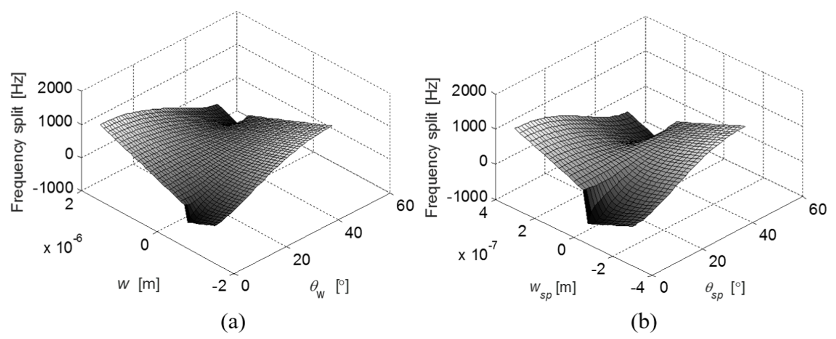
By varying the structural dimensions of the ring and suspension structures individually, the effects on the frequency split are quantified based on Equation (30). Figure 3a,b illustrate the frequency split arising from the variation of the ring geometry and the variation of the suspension geometry, respectively. The 4θ periodic manner of the ring/beam width variation determines a periodic frequency split when either θw or θsp changes every 90°. The maximum frequency split occurs when the width ring/beam variation (w or wsp) in the <110> crystal direction is larger than that in the <100> crystal direction as expected. The frequency split can be reduced to zero when either the ring structure or the supporting beams are assigned with specific widths and orientations.
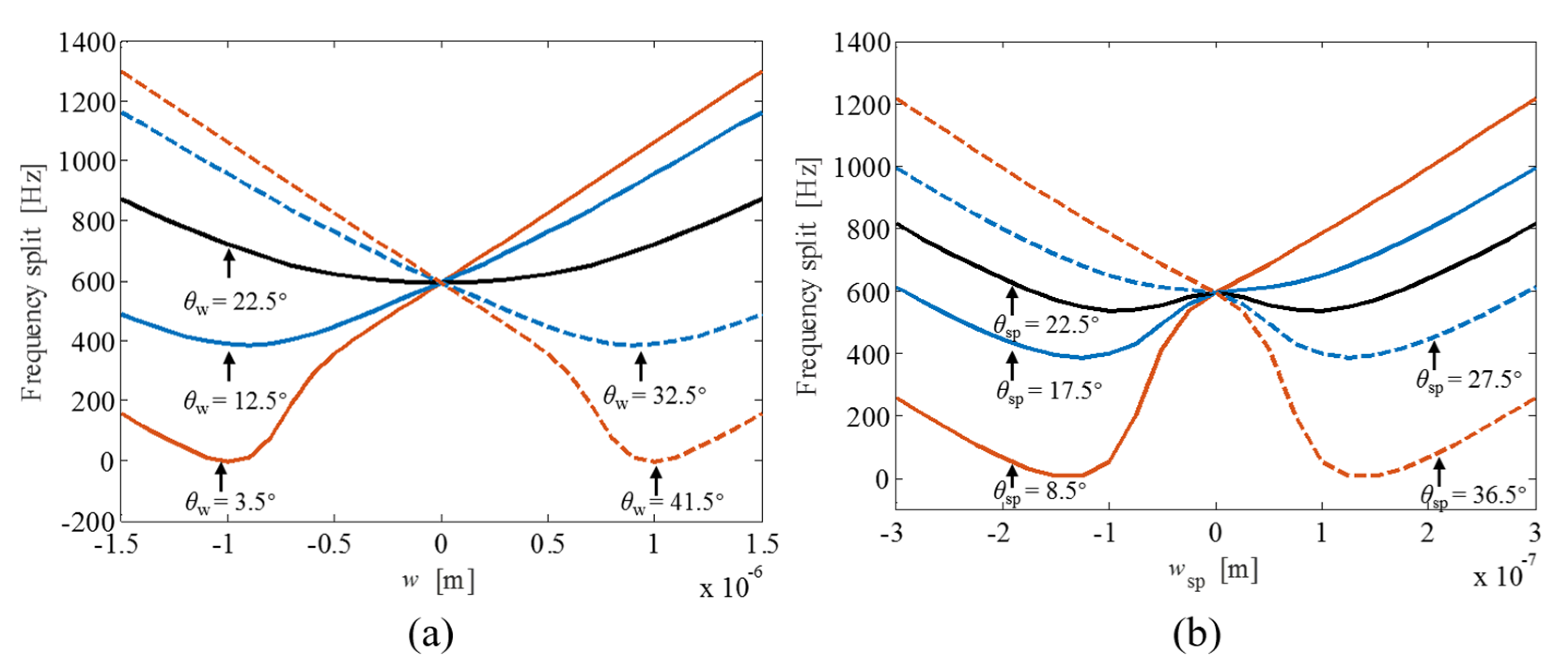
The effects of the ring/beam width variation of the ring-based gyroscope on the frequency split are shown in Figure 4. When the variation orientation (θw) of the ring is less than 3.5° or more than 41.5°, the frequencies of two vibration modes can be exactly matched with specific width variation of the ring structure. However, the frequency split in response to the width variation of the ring structure does not exhibit a mode-matched state without frequency split when the variation orientation (θw) of the ring ranges from 4° to 41°. The mode-matching state is similarly not exhibited for the case of the supporting beams with their variation orientation (θsp) assigned between 9° and 36°. When both θw and θsp are located at 22.5°, the frequency split has a symmetric and relatively flat response to the width variation of both the ring structure and the supporting beams. This indicates that the frequencies of both vibration modes are similarly affected by the ring/beam width variation at this specific variation orientation. When θw and θsp deflect from 22.5°, the frequency split as a function of the width variation w or wsp exhibits a “spoon”-shaped tendency. The bottom of the “spoon” intersects with the mode-matched line when θw ≤ 3.5° or θsp ≥ 41.5°. In addition, the variation of the beam width has a relatively larger contribution to the frequency split than the variation of the ring width because of the distributed property of the ring structure.
4.2. Modal Coupling
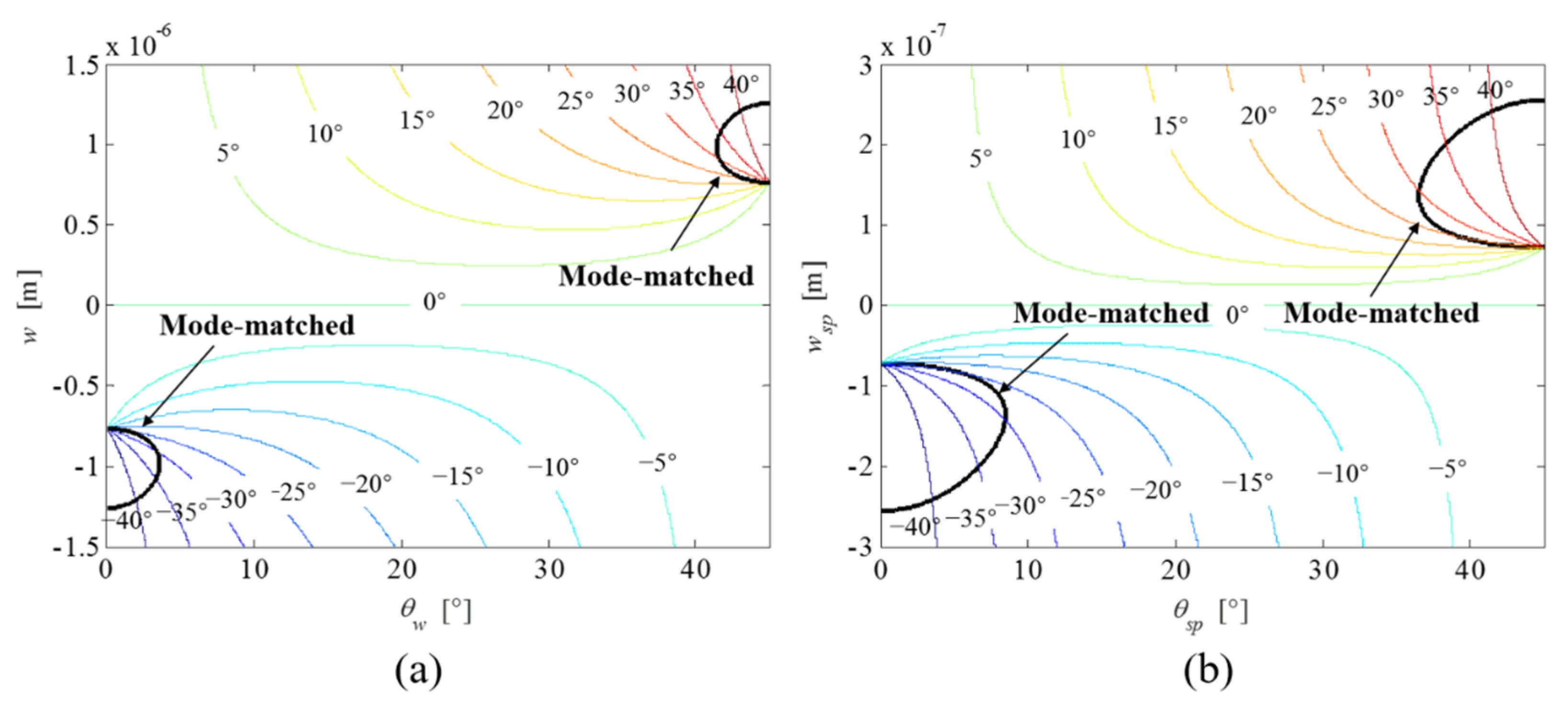
The principal axis of the 2θ mode pair, at the same time, rotates either clockwise or anti-clockwise in response to the structural variation of the ring structure and supporting beams. As shown in Figure 5, except for a perfect ring gyroscope, the principal axis of the 2θ mode pair rotates in a clockwise or anti-clockwise direction depending on the width variation w and wsp. When either w and wsp is larger than zero, the principal axis of the 2θ mode pair deflects in an anti-clockwise direction, and vice versa. When the width variations w and wsp are larger than 1.5 and 0.3 μm, respectively, the principal axis of the 2θ mode pair is dominated by their variation orientations (θw and θsp). As the black curved line indicated in Figure 5 two vibration modes are matched with specific variations of the width and orientation. For example, the mode-matched state occurs when w ranges from −0.75 to −1.25 μm, and θw ranges from 0° to 3.5°. Accordingly, the principal axis of the 2θ mode pair with respect to the 0° pickoff electrode varies from 0° to ±45°. Modal coupling arises from the deflection of the principal axis of the 2θ mode pair with respect to predefined electrode configuration. The principal axis of the mode-matched 2θ mode pair becomes least insensitive to the width variation when θw and θsp are 3.5° and 8.5°, respectively.
4.3. Geometrical Compensation
It requires precise geometrical compensation of the ring structure and the supporting beams to eliminate the frequency split between two vibration modes arising from material anisotropy. However, fabrication imperfection cannot be avoided completely even with precise and sophisticated processes. To reduce the effects of fabrication tolerance, it is required that the geometrical design of the ring gyroscope is insensitive and robust to the geometrical variation, ensuring the fabricated sensors having a minimum frequency split with little variation. As can be derived from the developed model, the vibratory ring gyroscope with the structural dimension variation of the ring structure, such as θw = 3.5° and w = −1.0 μm, has no frequency split between two vibration modes in theory, which varies less than 13 Hz, given a fabrication tolerance of w within ±0.1 μm. At the same time, the principal axis of the 2θ mode pair is about −32.5 ± 3.5° with the same fabrication tolerance. On the other hand, the compensation of frequency split through the structural dimension variation of the supporting beams is much less robust to the fabrication tolerance and results into much larger deflection of the principal axis of the 2θ mode pair. Two other reported geometrical compensation methods [15,16] for the ring-based gyroscopes based on the compensation method through the variation of the ring width were evaluated, by which the estimated frequency splits are more than 250 Hz and 400 Hz, respectively, as illustrated in Table 4. Therefore, the proposed geometrical compensation based on the developed model is advantageous due to its prediction accuracy and robustness to fabrication tolerance.
5. Conclusions
A mathematical model was presented for a ring-based gyroscope with considering the structural dimension variation and material anisotropy. The developed model is simplified with assuming linear material, constant damping, and residual stress-free properties. Furthermore, investigation about the effects on the vibration response in terms of the frequency split and modal coupling was performed. The predominant frequency split between two 2θ modes caused by the anisotropy of Young’s modulus was predicted using the developed model, in good agreement with measurements. Moreover, the resonance asymmetry of the ring-based gyroscope was parametrically studied through the structural dimension variations of both the ring structure and the supporting beams independently, arising from the fabrication imperfection or active design. The verticality variation of the deep trench as a result of fabrication imperfection slightly affects the frequency split of two vibration modes, exhibiting little influence on the principal axis of the 2θ mode pair. Mode-matching can be realized for the ring-based gyroscope by varying the lateral dimension of the ring structure, except the orientation of the 4θ variation (θw) locating between 4° and 41°. This frequency split-canceling effect is similarly exhibited for the structural dimension variation of the supporting beams, which requires more precise control of the beam width. At the same time, the lateral dimension variations of both the ring and the supporting beams induce modal coupling in terms of the rotation of the principal axis with respect to the predefined electrodes. Based on the above analysis, the optimal structural dimension of the vibratory ring gyroscope that guarantees a small range of frequency split and the deflection of the principal axis are obtained, necessitating robust fabrication and post-fabrication electrostatic tuning.
Author Contributions
Conceptualization, Z.M. and X.J.; methodology, Z.M. and X.C.; software, X.C. and Y.J.; validation, Z.M., X.C. and Y.J.; formal analysis, Z.M. and X.C.; investigation, Z.M., X.J. and X.C.; resources, Z.M., X.J., X.Z. and Z. J.; data curation, X.C.; writing—original draft preparation, Z.M. and X.C.; writing—review and editing, Z.M.; visualization, Z.M. and X.C.; supervision, Z.M. and Z.J.; project administration, Z.M., X.J., X.Z. and Z.J.; funding acquisition, Z.M. All authors have read and agreed to the published version of the manuscript.
Funding
This research was funded by the Zhejiang Provincial Natural Science Foundation of China under Grant LQ19F040011.
Institutional Review Board Statement
Not applicable.
Informed Consent Statement
Not applicable.
Conflicts of Interest
The authors declare no conflict of interest.
Appendix A
The capacitance of an electrode pair at θn is given by:
The full expression of each component in Equation (25) is shown as:
where:
The off-diagonal and cross-diagonal terms in the mass matrix are shown as follows. The term M12 and M21 representing in-pair modal coupling in terms of inertia is negligible when the width variation is small when compared to the width.
The term γ arising from Coriolis coupling when the ring rotates about the polar axis is:
where:
The stiffness coefficients of the ring structure are:
where:
The stiffness coefficients of the support springs are:
The linear electrostatic stiffness coefficients are:
where:
Ke12 and Ke21 representing in-pair modal coupling in terms of electrostatic stiffness are small compared to the mechanical stiffness and thus are neglected.
The f1, f2 terms contain the electrostatic actuation terms exciting the 2θ mode, and are derived from the electrostatic potential energy of the drive electrodes.
The full expression of er1, er2, esp1, and esp2 in Equation (30) is shown as:
References
- Putty, M.W. A micromachined vibrating ring gyroscope. Ph.D. Thesis, University of Michigan, Ann Arbor, MI, USA, 1995. [Google Scholar]
- Shin, D.; Ahn, C.; Chen, Y.; Hong, V.; Ng, E.; Yang, Y.; Kenny, T. Electrostatic tuning of temperature coefficient of frequency of anisotropic disk-shaped resonators. In Proceedings of the 4th IEEE International Symposium on Inertial Sensors and Systems (INERTIAL), Kauai, HI, USA, 27–30 March 2017. [Google Scholar]
- Yoon, S.; Park, U.; Rhim, J.; Yang, S.S. Tactical grade mems vibrating ring gyroscope with high shock reliability. Microelectron. Eng. 2015, 142, 22–29. [Google Scholar] [CrossRef]
- Hossain, S.T.; Mcwilliam, S.; Popov, A.A. An investigation on thermoelastic damping of high-q ring resonators. Int. J. Mech. Sci. 2016, 106, 209–219. [Google Scholar] [CrossRef] [Green Version]
- Schwartz, D.; Kim, D.J.; M’Closkey, R.T. Frequency tuning of a disk resonator gyro via mass matrix perturbation. In Proceedings of the 2008 American Control Conference, Seattle, WA, USA, 11–13 June 2008. [Google Scholar]
- Gallacher, B.J.; Hedley, J.; Burdess, J.S.; Harris, A.J.; Rickard, A.; King, D.O. Electrostatic correction of structural imperfections present in a microring gyroscope. J. Microelectromech. Syst. 2015, 14, 209–219. [Google Scholar] [CrossRef]
- Cui, J.; Bai, Z.; Zhao, Q.; Yang, Z.; Yan, G. Initial frequency split reduction of mems ring gyroscope based on cascaded springs geometrical compensation. Electron. Lett. 2019, 55, 806–808. [Google Scholar]
- Qin, Z.; Gao, Y.; Jia, J.; Ding, X.; Huang, L.; Li, H. The effect of the anisotropy of single crystal silicon on the frequency split of vibrating ring gyroscopes. Micromachines 2019, 10, 126. [Google Scholar] [CrossRef] [Green Version]
- Eley, R.; Fox, C.H.J.; McWilliam, S. Anisotropy effects on the vibration of circular rings made from crystalline silicon. J. Sound Vibr. 1999, 228, 11–35. [Google Scholar] [CrossRef]
- Davin, J. Simulating the performance of ring-based coriolis vibrating gyroscopic sensors. Microsyst. Technol. 2019, 25, 139–149. [Google Scholar]
- Mcwilliam, S.; Ong, J.; Fox, C.H.J. On the statistics of natural frequency splitting for rings with random mass imperfections. J. Sound Vibr. 2015, 279, 453–470. [Google Scholar] [CrossRef]
- Asokanthan, S.F.; Cho, J. Dynamic response-based characterization of ring-based vibratory angular rate sensors. J. Mech. Sci. Technol. 2017, 21, 965–969. [Google Scholar] [CrossRef]
- Bisegna, P.; Caruso, G. Frequency split and vibration localization in imperfect rings. J. Sound Vibr. 2007, 306, 691–711. [Google Scholar] [CrossRef]
- Rourke, A.K.; Mcwilliam, S.; Fox, C.H.J. Frequency trimming of a vibrating ring-based multi-axis rate sensor. J. Sound Vibr. 2005, 280, 495–530. [Google Scholar] [CrossRef]
- Shu, Y.; Hirai, Y.; Tsuchiya, T.; Tabata, O. Geometrical compensation for mode-matching of a (100) silicon ring resonator for a vibratory gyroscope. Jpn. J. Appl. Phys. 2019, 58, SSDL06. [Google Scholar] [CrossRef]
- Ahn, C.H.; Ng, E.J.; Hong, V.A.; Yang, Y.; Lee, B.J.; Flader, I.; Kenny, T.W. Mode-matching of wineglass mode disk resonator gyroscope in (100) single crystal silicon. J. Microelectromech. Syst. 2015, 24, 343–350. [Google Scholar] [CrossRef]
- Hu, Z.; Gallacher, B.J. Precision mode tuning towards a low angle drift MEMS rate integrating gyroscope. Mechatronics 2018, 56, 306–317. [Google Scholar] [CrossRef] [Green Version]
- Taheri-Tehrani, P.; Challoner, A.D.; Horsley, D.A. Micromechanical rate integrating gyroscope with angle-dependent bias compensation using a self-precession method. IEEE Sens. J. 2018, 18, 3533–3543. [Google Scholar] [CrossRef]
- Yoon, S.W.; Lee, S.; Najafi, K. Vibration sensitivity analysis of mems vibratory ring gyroscopes. Sens. Actuator A -Phys. 2011, 171, 163–177. [Google Scholar] [CrossRef]
- Napoli, V.D.; McWilliam, S.; Popov, A.A. Frequency Splitting in MEMS Ring-based Coriolis Vibrating Gyroscopes Caused by Support Non-Linearity. Proceedings 2018, 2, 755. [Google Scholar] [CrossRef] [Green Version]
- Liang, D.; Yang, X.; Zhang, W. Linear, nonlinear dynamics, and sensitivity analysis of a vibratory ring gyroscope. Theor. Appl. Mech. Lett. 2018, 8, 393–403. [Google Scholar] [CrossRef]
- Sieberer, S.; McWilliam, S.; Popov, A.A. Nonlinear electrostatic effects in MEMS ring-based rate sensors under shock excitation. Int. J. Mech. Sci. 2019, 157, 485–497. [Google Scholar] [CrossRef]
- Ayazi, F.; Sorenson, L.; Tabrizian, R. Energy dissipation in micromechanical resonators. In Proceedings of the SPIE—The International Society for Optical Engineering, Atlanta, GA, USA, 13 May 2011. [Google Scholar]
- Duwel, A.; Gorman, J.; Weinstein, M.; Borenstein, J.; Ward, P. Experimental study of thermoelastic damping in MEMS gyros. Sens. Actuator A -Phys. 2003, 103, 70–75. [Google Scholar] [CrossRef] [Green Version]
- Morozov, O.V.; Uvarov, I.V. Determination of Vibration Axes of the Micromachined Ring Resonator for the Modal Tuning Purposes. In Proceedings of the International Conference on Micro- and Nano-Electronics 2018, Zvenigorod, Russia, 1–3 October 2018. [Google Scholar]
- Karimzadeh, A.; Ahmadian, M.T. Vibrational characteristics of size-dependent vibrating ring gyroscope. Sci. Iran. 2018, 25, 3151–3160. [Google Scholar] [CrossRef] [Green Version]
Figure 1.
The 2θ mode pair of the ring-based gyroscope with elliptic mode shapes consisting of four nodes and four anti-nodes.
Figure 1.
The 2θ mode pair of the ring-based gyroscope with elliptic mode shapes consisting of four nodes and four anti-nodes.

Figure 2.
Schematic view of a ring resonator and a section of the ring and the surrounding electrode locating at θ.
Figure 2.
Schematic view of a ring resonator and a section of the ring and the surrounding electrode locating at θ.

Figure 3.
The influence of the width and orientation of the ring (a) and the supporting beams (b) on the frequency split.
Figure 3.
The influence of the width and orientation of the ring (a) and the supporting beams (b) on the frequency split.

Figure 4.
The influence of the width variation of both the ring (a) and the supporting beams (b) on the frequency split.
Figure 4.
The influence of the width variation of both the ring (a) and the supporting beams (b) on the frequency split.

Figure 5.
The influence of width variation of both the ring (a) and the supporting beams (b) on the principal axis of the 2θ mode pair, which is represented by contour maps. The black curved lines indicate the mode-matched solutions.
Figure 5.
The influence of width variation of both the ring (a) and the supporting beams (b) on the principal axis of the 2θ mode pair, which is represented by contour maps. The black curved lines indicate the mode-matched solutions.


Table 1.
Models of ring-based gyroscopes.
| Model | Material Anisotropy | Mass Asymmetry | Non-Ideal Ring | Non-Ideal Beam | Non-Ideal Trench | Reference |
|---|---|---|---|---|---|---|
| FEM | Yes | Yes | Yes | Yes | No | [7] |
| FEM | Yes | Yes | Yes | No | No | [8] |
| Analytical | Yes | No | No | No | No | [9] |
| Analytical | Yes | Yes | No | No | No | [10] |
| Analytical | Yes | Yes | Yes | Yes | Yes | This work |
Table 2.
Properties of ring-based gyroscopes.
| Parameter | Value | Description |
|---|---|---|
| E0 (GPa) | 150 | Average Young’s modulus of (100) SCS |
| ρ (kg/m3) | 2330 | Bulk density |
| Rr (mm) | 1 | Ring radius |
| Wr (μm) | 11 | Ring width |
| Hr (μm) | 60 | Ring thickness |
| Δθ (°) | 18 | Electrode radian |
| rsp (μm) | 472.5 | Beam radius |
| Wsp (μm) | 5 | Beam width |
| d0 (μm) | 4 | Electrode and undeformed ring gap |
| Cinp (pF) | 1 | Feedback reference capacitance in CV circuit |
| Vdn (V) | 2.5 | Drive voltage |
| Vp (V) | 2.5 | Polarization voltage |
| Vb (V) | 0 | Bias voltage at the pick-off |
Table 3.
Frequency split considering anisotropic Young’s modulus.
| Method | Frequency Split (Hz) | Description |
|---|---|---|
| Analytical | 844 | Equation (32) |
| Analytical | 593 | Equation (31) |
| FEM | 799 | COMSOL |
| Experimental | 625 (σ =18 Hz) | nine as fabricated samples |
Publisher’s Note: MDPI stays neutral with regard to jurisdictional claims in published maps and institutional affiliations. |
© 2021 by the authors. Licensee MDPI, Basel, Switzerland. This article is an open access article distributed under the terms and conditions of the Creative Commons Attribution (CC BY) license (https://creativecommons.org/licenses/by/4.0/).
Share and Cite
MDPI and ACS Style
Ma, Z.; Chen, X.; Jin, X.; Jin, Y.; Zheng, X.; Jin, Z. Effects of Structural Dimension Variation on the Vibration of MEMS Ring-Based Gyroscopes. Micromachines 2021, 12, 1483. https://0-doi-org.brum.beds.ac.uk/10.3390/mi12121483
AMA Style
Ma Z, Chen X, Jin X, Jin Y, Zheng X, Jin Z. Effects of Structural Dimension Variation on the Vibration of MEMS Ring-Based Gyroscopes. Micromachines. 2021; 12(12):1483. https://0-doi-org.brum.beds.ac.uk/10.3390/mi12121483
Chicago/Turabian StyleMa, Zhipeng, Xiaoli Chen, Xiaojun Jin, Yiming Jin, Xudong Zheng, and Zhonghe Jin. 2021. "Effects of Structural Dimension Variation on the Vibration of MEMS Ring-Based Gyroscopes" Micromachines 12, no. 12: 1483. https://0-doi-org.brum.beds.ac.uk/10.3390/mi12121483
Note that from the first issue of 2016, this journal uses article numbers instead of page numbers. See further details here.