Recovery of Iron from Copper Slag Using Coal-Based Direct Reduction: Reduction Characteristics and Kinetics

1
School of Resources and Safety Engineering, Wuhan Institute of Technology, Wuhan 430205, China
2
School of Minerals Processing and Bioengineering, Central South University, Changsha 410083, China
*
Author to whom correspondence should be addressed.
Minerals 2020, 10(11), 973; https://0-doi-org.brum.beds.ac.uk/10.3390/min10110973
Submission received: 9 September 2020
/
Revised: 28 October 2020
/
Accepted: 29 October 2020
/
Published: 31 October 2020
(This article belongs to the Special Issue Utilisation of Industrial Byproducts for Materials and Metallurgical Applications)
Abstract
:The Fe3O4 and Fe2SiO4 in copper slag were successfully reduced to metallic iron by coal-based direct reduction. Under the best reduction conditions of 1300 °C reduction temperature, 30 min reduction time, 35 wt.% coal dosage, and 20 wt.% CaO dosage (0.75 binary basicity), the Fe grade of obtained iron concentration achieved 91.55%, and the Fe recovery was 98.13%. The kinetic studies on reduction indicated that the reduction of copper slag was controlled by the interfacial reaction and carbon gasification at 1050 °C. When at a higher reduction temperature, the copper slag reduction was controlled by the diffusion of the gas. The integral kinetics model research illustrated that the reaction activation energy increased as the reduction of copper slag proceeded. The early reduction of Fe3O4 needed a low reaction activation energy. The subsequent reduction of Fe2SiO4 needed higher reaction activation energy compared with that of Fe3O4 reduction.
1. Introduction
In China’s copper industry, pyrometallurgy technology is presently the primary process for crude copper production [1,2]. In the copper pyrometallurgy process, 2–2.5 tons (metric) of copper slag byproducts are produced for every ton of crude copper produced [3,4,5]. As some papers have reported, in 2019, China’s copper output reached 9.8 million tons, and more than 20 million tons of copper slag were produced [6,7]. The accumulated stockpile of copper slag over the years exceeds 120 million tons [8]. The huge stockpile of copper slag encroaches on the land and pollutes the soil and groundwater [9]. Furthermore, the copper slag also contains valuable metals including 35–45 wt.% Fe [10], which suggests it is worth recycling and utilizing as a secondary resource. On the other hand, China lacks high-quality iron ore and imports over one billion tons of iron ore per year. In 2017, China’s import dependence ratio rose to 87.6% [11]. Therefore, utilizing the domestic low-grade Fe-bearing resource is necessary and urgent.
Recently, many researchers have published studies on the utilization of copper slag, for example, as a cement additive [12], for preparing abrasive tools [13], for pavement materials [14], and for preparing glasses [15]. These processes could utilize the copper slag at low cost. However, these crude utilization methods neglect the recovery of valuable metals in copper slag, resulting in a waste of resources. Furthermore, the metal elements in copper slag (Fe, Ni, Zn, Cu, etc.) may cause environmental damage [16,17]. Therefore, the recovery of valuable metals is an important issue in the utilization of copper slag. Iron is the primary valuable metal in copper slag, and it mainly exists in copper slag in the form of fayalite (2FeO·SiO2) [18]. As previous research has reported, fayalite has high refractoriness and is difficult to be reduced by a reductant like carbon monoxide or carbon [19]. Therefore, fayalite is generally considered a kind of refractory iron compound [20]. At present, the mainstream iron recovery processes from copper slag mainly include the hydrometallurgy route [21], smelting iron alloy [22], and direct reduction (DR) process [23]. However, it is inefficient to utilize copper slag by the hydrometallurgy route due to the complex mineralogical properties of copper slag [24]. Moreover, as we know, the melting point of fayalite in the copper slag is very high, so it is hard to smelt [25]. Therefore, the energy consumption of the smelting process of copper slag is very high. In comparison, the direct reduction process may be the best process for recovering iron from copper slag considering the efficiency, cost, recovery rate, and operability [26].
Many scholars have published research on the direct reduction of fayalite for the purposes of iron recovery from copper slag [27,28,29]. Cao et al. [30] adopted rotary hearth furnaces to conduct the direct reduction process for the iron recovery from copper slag. Under optimum conditions of the reduction temperature of 1280 °C and the reduction time of 35 min, the direct reduction of iron (DRI) powder with an iron grade of 90.35% was obtained, and the iron recovery rate was 89.70%. A recent paper showed that the fayalite in the copper slag could be reduced by walnut shell char. The iron concentration with 73.20 wt.% iron grade and 95.56% recovery rate was obtained under a reduction temperature of 1300 °C [31]. For these reasons, Fe resources contained in copper slag can be recycled efficiently by the direct reduction method. The obtained metallic iron produced, with more 90% iron content, is an excellent raw material for the iron and steel industry [32].
Based on the above analysis, there is a lack of study on the reduction kinetics of copper slag. As the published papers report, the iron in copper slag mainly exists in the form of fayalite [33]. The structure and property of the fayalite are very stable during the reduction process [34], making it difficult to reduce to metallic iron. The reduction kinetics determines the efficiency and energy consumption of the reduction process and the direct reduction of iron (DRI) product quality. In this study, the effects of direct reduction temperature and time, coal dosage, and CaO dosage on the direct reduction–magnetic separation process were investigated. The kinetics of direct reduction was clarified by kinetic model calculations.
2. Materials and Methods
2.1. Materials
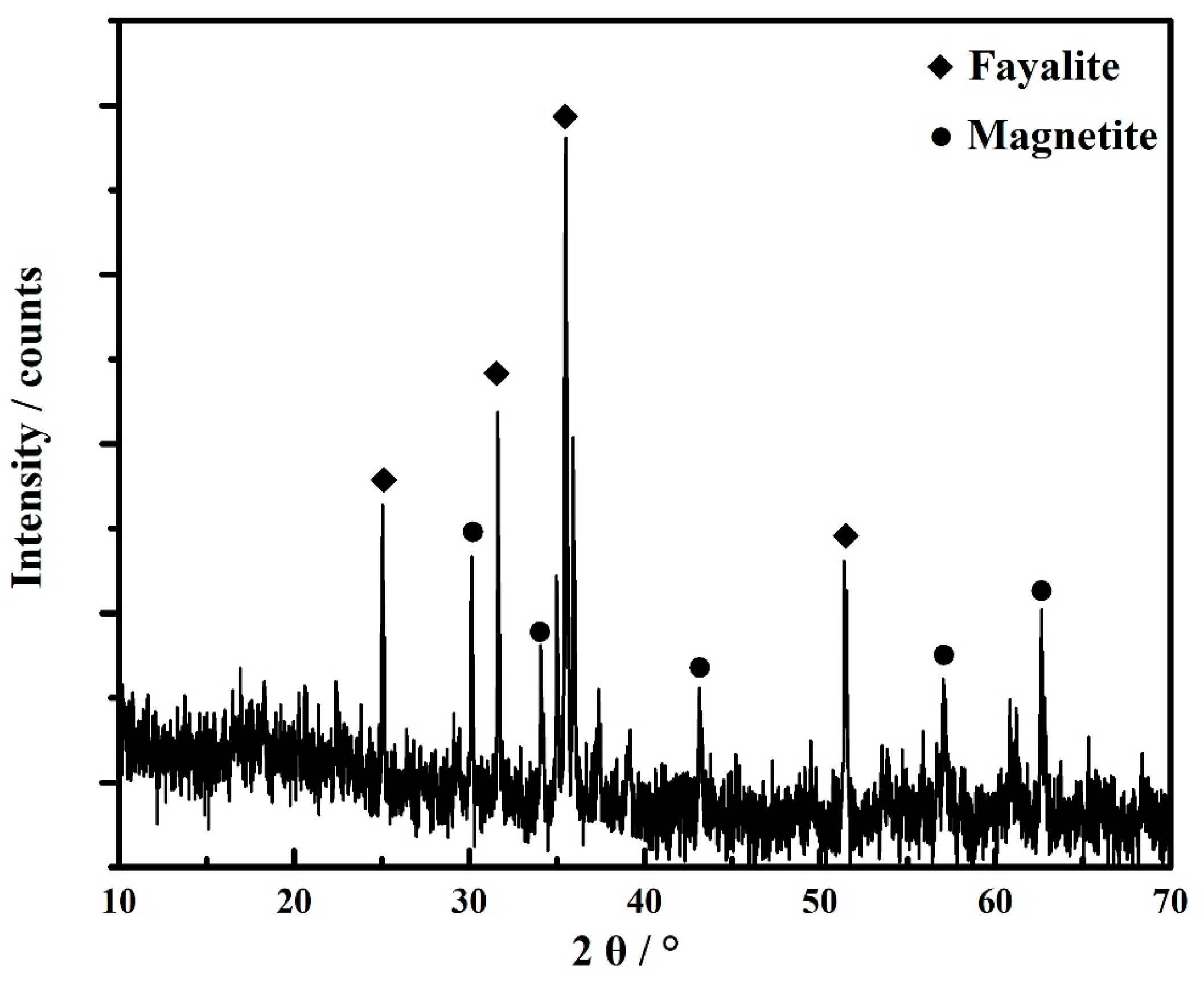
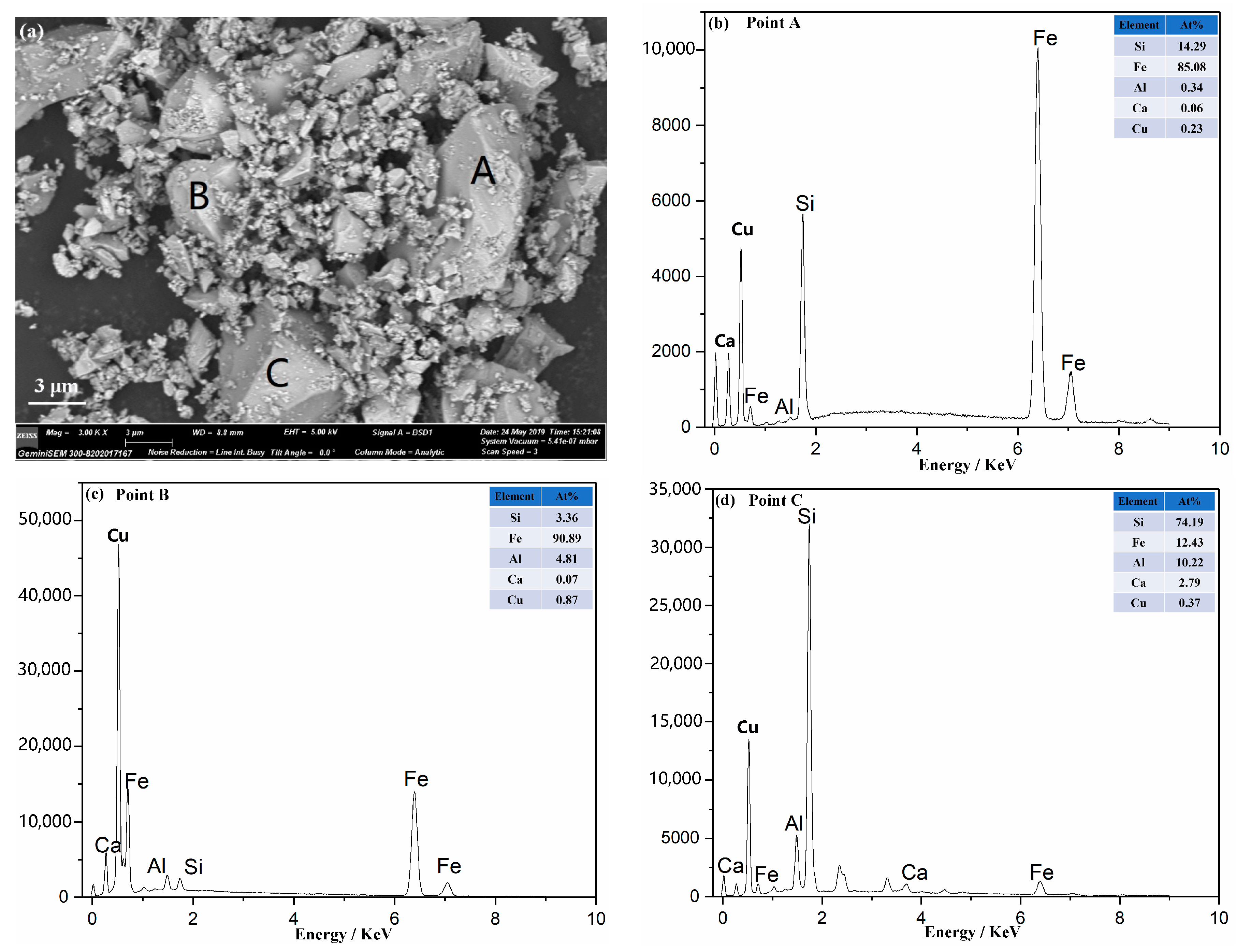
The copper slag used in this study came from Tongling Nonferrous Metals Group Holdings Co., Ltd. (Tongling, China). About 200 kg samples were collected from the different areas of the copper slag storage bin. The 200 kg samples were thoroughly mixed and bagged to ensure that the sample taken in each experiment was representative. The obtained copper slag was crushed into a fine powder with particle size less than 2 mm by a roll crushing mill. Subsequently, 1 g of the crushed copper slag powder continued to be ground to a particle size less than 30 μm in an agate mortar and was used to conduct the XRD test. The XRD spectrogram was recorded on Bruker AXS D8 advanceX diffractometer (Bruker, Billerica, MA, USA) using the Cu Kα. The scanning range of the 2θ angle was from 10° to 70°, and the scanning step and measuring time were 0.02° and 0.2 s/step, respectively. The XRD pattern of copper slag is displayed in Figure 1. Scanning electron microscope (SEM) (Quanta 200, FEI Corporation, Hillsboro, OR, USA) analysis was adopted to observe the micro appearance of copper slag, and energy-dispersive spectrometer (EDS) (Quanta 200, FEI Corporation) analysis was used to measure the atom content on the sample’s surface. Thirty milligrams of copper slag sample were applied to the conductive adhesive and put on the sample stage. The excess sample powder was purged by nitrogen. Then, a copper slag sample was observed by the SEM. The micrography and EDS analyses of copper slag are shown in Figure 2.
Additionally, the main chemical composition of copper slag and bentonite was measured by an X-ray fluorescence spectrometer (XRF, Axios Max, Malvern Panalytical, Malvern, UK). Five grams of the sample was first dried and ground. Then, the sample was put in a mold and tableted under 2000 MPa pressure for 1 min. The sample tablet was used to conduct the XRF test. The detailed analysis results of copper slag, coal and bentonite’s chemical compositions are listed in Table 1, Table 2 and Table 3, respectively. The proximate analysis of coal was conducted using a coal proximate analyzer (5E-MAG6600, Kaiyuan company, Changsha, China). One gram of coal sample was put into a corundum crucible. The crucible was placed on a thermo-balance and heated to 1300 °C to detect the moisture, volatiles, ash, fixed carbon, and sulfur contents of the coal sample. The detailed results are shown in Table 2.
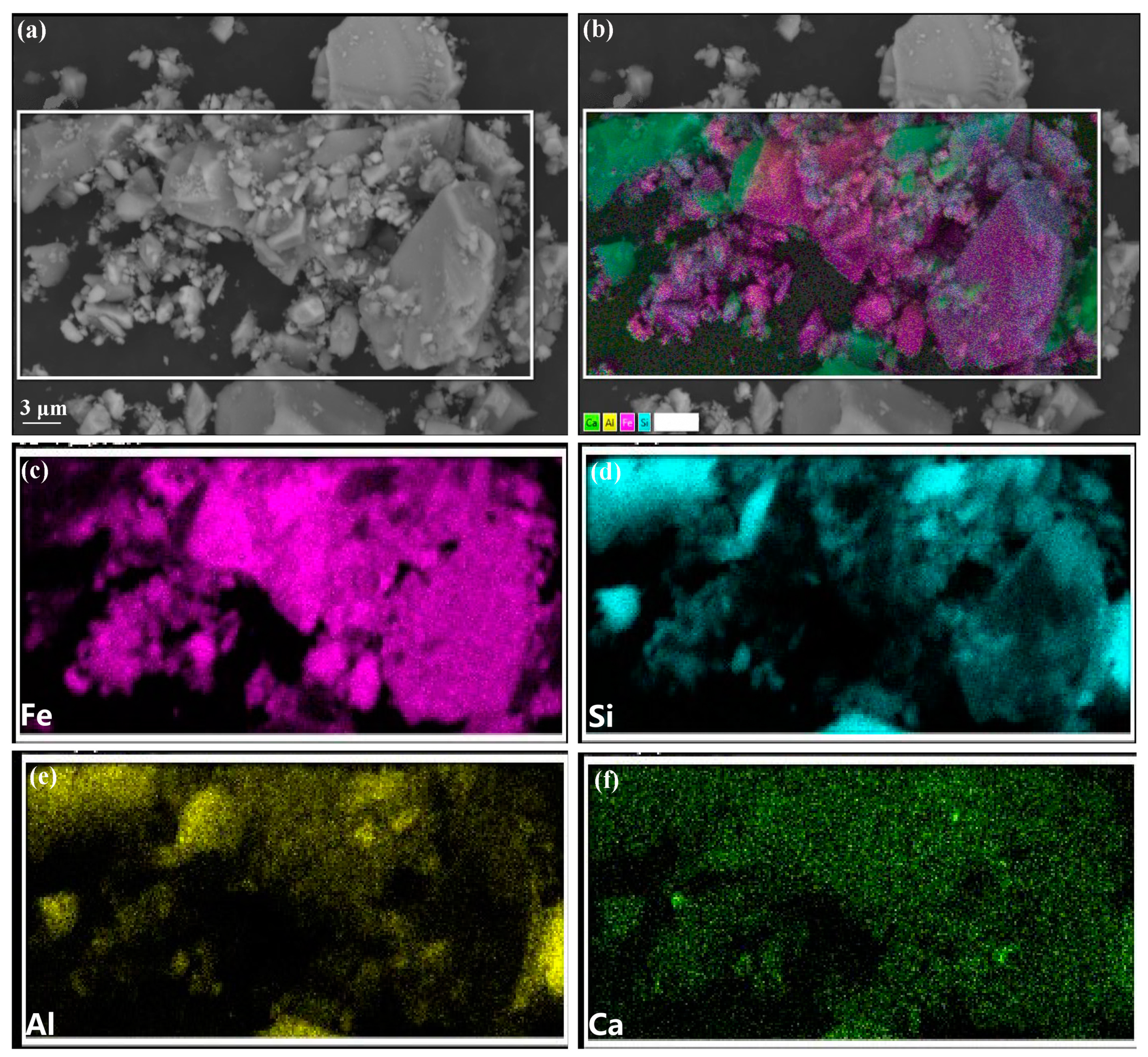
The diffraction peaks shown in Figure 1 indicate that the iron in copper slag primarily exists in the form of fayalite and magnetite. There were also many stray interferential peaks near the baseline. The primary reason is that the copper slag adopted in this study is quenched slag. During the quenching process, some minerals are incompletely crystallized, forming the amorphous glass-phase substance. The stray interferential peaks belong to the glassy materials. The chemical composition analysis of copper slag shows that the iron grade of this copper slag sample is quite high, reaching 47.81 wt.%. The SiO2 content of the copper slag was 24.72 wt.%, indicating that this copper slag sample belonged to acid slag. Some extra CaO additive was needed to adjust the basicity in the direct reduction experiments [35]. The micrography of copper slag shown in Figure 2 indicates that the particle size of copper slag was about 3–10 μm after grinding, which is favorable for the subsequent reduction roasting. The energy-dispersive spectrometer (EDS) analyses showed that the main elements of copper slag were Fe and Si. The EDS results showed that the fayalite, magnetite, and quartz in the copper slag were tightly bound together. It is difficult to separate them using conventional mineral processing methods. The SEM–EDS mapping shown in Figure 3 shows that the Fe was evenly distributed inside the copper slag. A considerable part of the Fe also overlapped with Si in the mapping area, indicating that this part of Fe was closely combined with Si and belonged to the Fe2SiO4.
In the direct reduction experiments, the additives include reductant coal, flux CaO, and binder bentonite. The additives used in this research were obtained from the Baowu Steel company (Wuhan, China). The physicochemical properties of coal and bentonite are shown in Table 2 and Table 3, respectively. The results shown in Table 2 indicate that the content of the volatile matters is quite high. The high content of volatile matter in the coal can improve the reduction process. The fixed carbon content of the coal is 52.39 wt.%, which is the main reductant in the direct reduction process. Bentonite is used as a binder to increase the mechanical strength of copper slag pellets in the pelletizing process. The main components of bentonite are SiO2 and Al2O3.
2.2. Experimental Methods
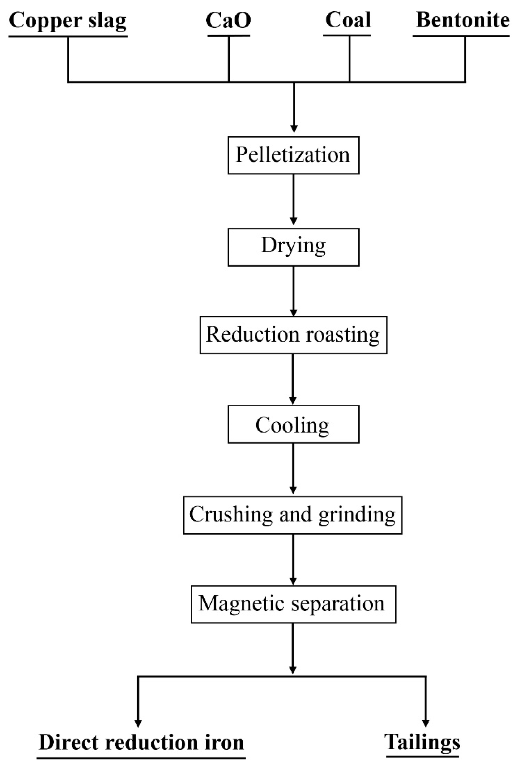
As shown in Figure 4, the mixture of copper slag, CaO, coal, and bentonite were used for pelletizing. The dosage of bentonite was 4.0 wt.%, and the dosages of CaO and coal depended on the conditions in the experiments. The pellets with diameters of 8–16 mm were sifted out as the qualified pellets. Then, the pellets were dried in an air-dry oven at 105 °C. During the drying process, the pellets were weighed every hour until the weight of pellets stayed constant to ensure that all free moisture in the pellets was removed. The coal-bearing green pellets were roasted after drying. Subsequently, the roasted pellets were crushed to a size less than 2 mm using a jaw crusher. The roasted pellet particle was ground using a ball mill. The size of particles was controlled to be below 74 μm. The magnetic separation was conducted in a magnetic separator. The magnetic field intensity was controlled at 80 KA/m. The direct reduction of iron was obtained by the magnetic separation.
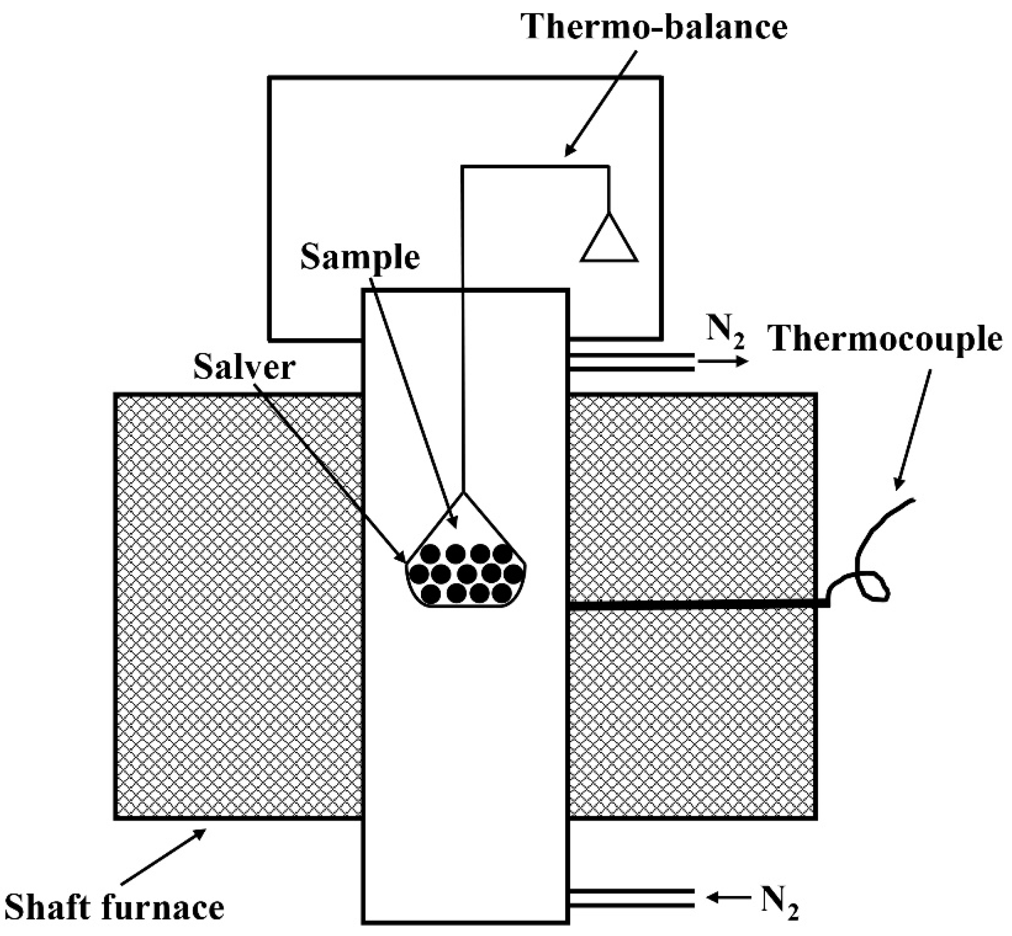
The reduction kinetics of copper slag was investigated by a thermo-balance, and the structure chart of the equipment is shown in Figure 5. Two hundred grams of dried pellets were placed on the salver of the balance and heated by shaft furnace. Nitrogen was used as the protective gas to avoid the oxidation of iron.
2.3. Reduction Kinetic Models
The reduction kinetics were defined as the relationship between the reduction degree of copper slag and the reduction time [36]. The reduction degree α was obtained by the following Equation (1):
where α is the reduction degree of the copper slag; WLt is the weight loss of the copper slag pellet at time t, which is the difference between the initial weight m0 and the weight at time t mt; and WL is the theoretical weight loss during the reduction process, which is the sum of the O atom mass of iron-bearing compound (mO), the fixed C mass of coal (mC), and the volatile matter mass of coal (mV).
In this study, the single restricted-link kinetic models were used to analyze the reduction of iron-bearing compounds in copper slag. When the interfacial chemical reaction is the controlling step of the reduction reaction, the kinetic model can be expressed as follows [37,38,39]:
When the gasification of carbon is the controlling step of the reduction reaction, the kinetic model can be expressed as follows:
When the diffusion of gas through the pellet is the controlling step of the reduction reaction, the kinetic model could be expressed as follows:
where k is the reaction constant, t is time, and α is the reduction degree.
The reaction activation energy was calculated according to the Arrhenius Equation, which can be expressed as follows [40]:
Taking the logarithm of Equation (5), the linear formula of the Arrhenius Equation is expressed as follows:
where A is the pre-exponential factor, s−1; Eα is the reaction activation energy, J·mol−1; R is the ideal gas constant 8.314 J·mol−1·K−1; T is the temperature, K.
In order to investigate the reduction kinetics of copper slag in the different stages of the copper slag reduction process, integral kinetics research was introduced into this study. The details of this method are shown below:
The relationship between α and t can be expressed as Equation (7):
Substituting Equation (5) into Equation (7) and conducting integration, we could obtain the following Equation (8):
The Equation (8) could transfer to the following formula:
Taking the logarithm of the Equation (9), the linear formula could be expressed by the following Equation (10):
where A is the pre-exponential factor, s−1; Eα is the reaction activation energy, J·mol−1; R is the ideal gas constant 8.314 J·mol−1·K−1; T is the temperature, K.
3. Results and Discussion
3.1. Thermomechanical Analysis
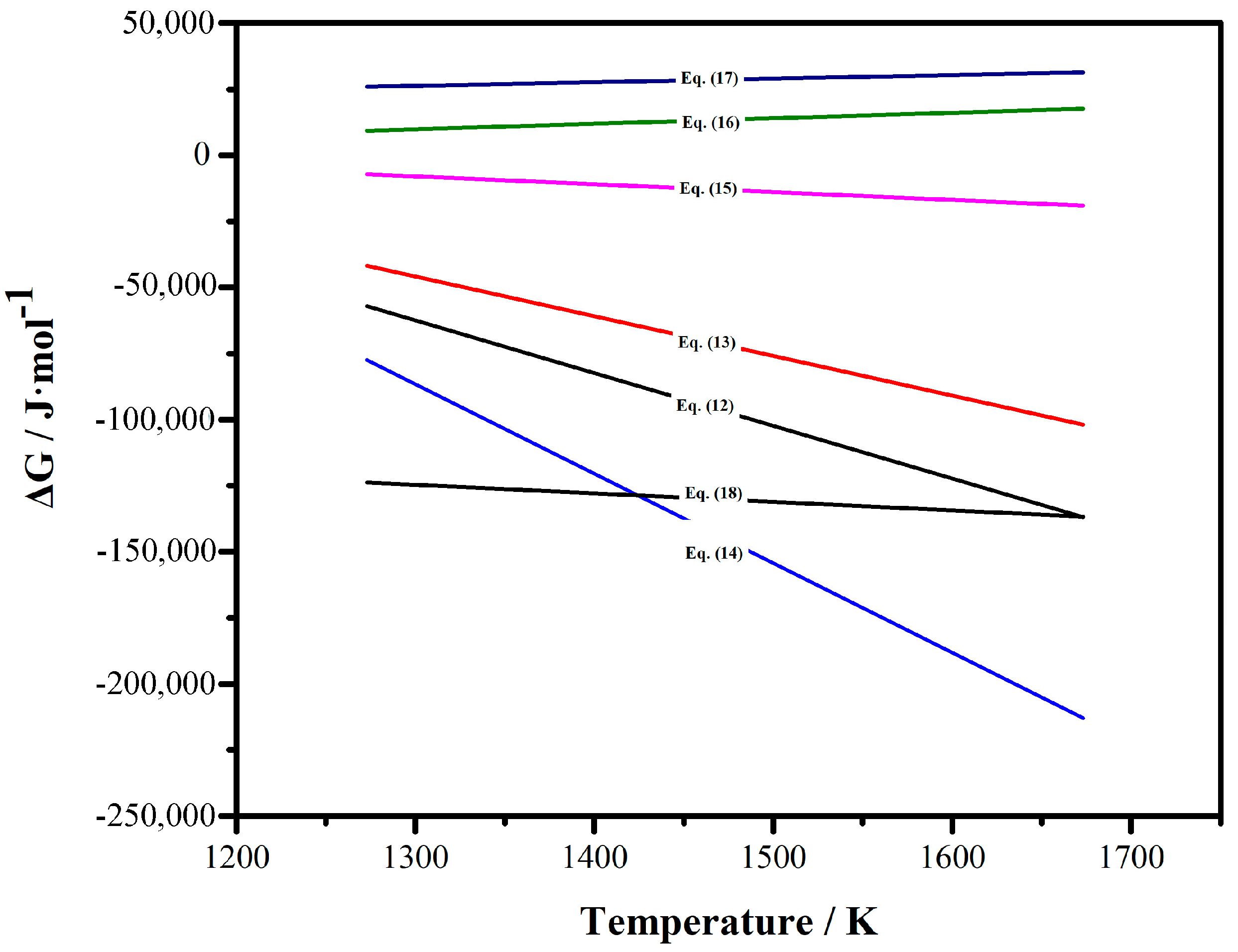
The thermodynamics of the reduction reactions within a certain temperature range is an important indicator to judge whether the reaction can proceed. In the reduction roasting process, the reactions primarily included the carbon gasification and the reduction of iron-bearing compounds. The reaction and thermodynamic Equations are as follows [30,36,41]:
The Gibbs equation lines of the reactions were showed in Figure 6. From Equations (11)–(18), it can be found that under experimental temperature conditions (1050–1300 °C), Fe3O4 and FeO can both be reduced by carbon and carbon monoxide. Equation (17) shows that Fe2SiO4 cannot be reduced directly by carbon monoxide, but in the presence of CaO, Fe2SiO4 can decompose easily and produce FeO, which can be reduced by carbon and carbon monoxide simultaneously. Equation (14) indicates that Fe2SiO4 can be reduced by carbon directly. However, this reaction proceeds very slowly on the kinetic level. Therefore, it can be inferred that carbon monoxide was still the primary reductant of the copper slag reduction. The above thermodynamic analysis indicates that the iron-bearing compound in the copper slag can be reduced to metallic iron by carbon and carbon monoxide. Furthermore, the premise that the Gibbs function can be established is when ΔCp is zero. Therefore, the above analyses of the Gibbs Equations were under theoretical conditions. In the real reaction process, whether a reaction can occur also depends on the system pressure, reactant concentration, reaction rate, etc. Therefore, the reaction kinetic model is an important tool to investigate the reaction process.
3.2. The Direct Reduction Characteristics
3.2.1. The Effects of Reduction Temperature and Time
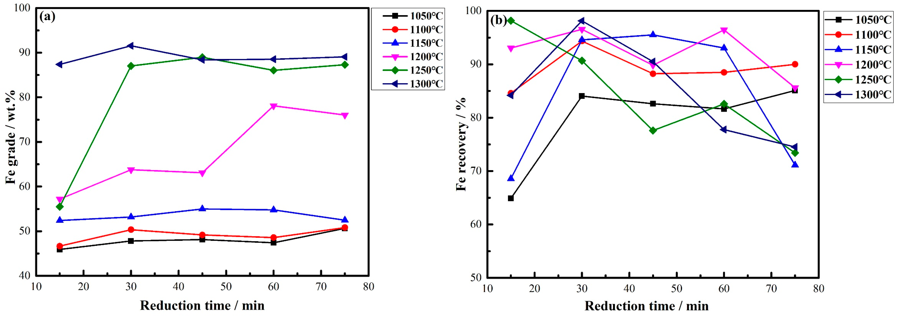
As can be seen that from the above thermomechanical analysis, the reduction temperature is an important factor for direct reduction. The Fe3O4 and Fe2SiO4 could be reduced to metallic iron in a certain temperature range. The reduction time also influences the reduction effect of copper slag. The Fe grade and recovery are listed in Figure 7 under different reduction temperatures and times. The coal and CaO dosage were set at 35 wt.% and 20 wt.%, respectively. The Fe grade refers to the iron content in the obtained direct reduction iron, and the Fe recovery is the ratio of iron content in direct reduction iron to that in copper slag.
As shown in Figure 7a, the increasing reduction temperature significantly improved the Fe grade of the concentrate. The higher temperature made Fe2SiO4 and Fe3O4 be reduced rapidly by carbon and carbon monoxide. On the other hand, the FeO was reduced to metallic Fe under a high temperature. The formation of metallic Fe greatly increased the Fe grade of the concentrate. From the Figure 7b, it was found that the Fe recovery increased first and then declined. Excessively extending the reduction time would cause the generated metallic Fe, CaSiO3, and glass-phase gangue to be intercalated and adhered to each other. The metallic iron wrapped in the glass phase was difficult to dissociate, leading to the decline of the Fe recovery. The optimum conditions were determined as 1300 °C and 30 min from the above results. Under this condition, the max Fe grade and recovery were 91.55% and 98.14%, respectively.
3.2.2. The Effect of Coal Dosage
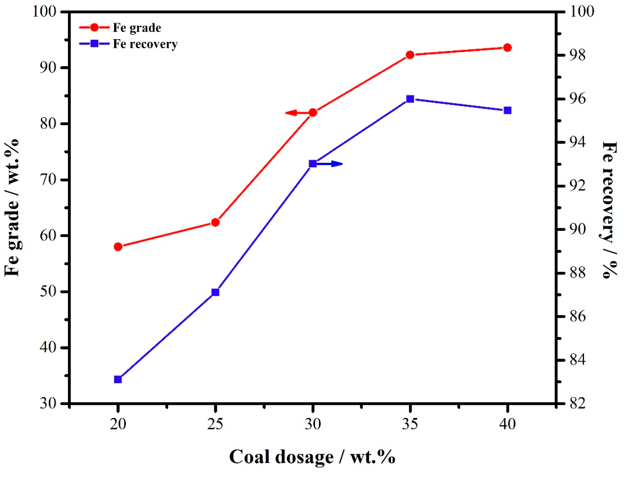
The reductant dosage is crucial to the copper slag reduction process. During the reduction roasting, the carbon gasified and produced carbon monoxide, thus keeping a reducing atmosphere in the reactor. The effects of the coal dosage on the Fe grade and recovery are shown in Figure 8. The reduction temperature and time were set at 1300 °C and 30 min, respectively, and the CaO dosage was set at 20 wt.%.
In order to keep a strong reducing atmosphere in the roasting furnace, an excessive amount of reductant is generally added. The bituminous used in this study began to decompose at 450 °C, therefore, at the experimental temperature, coal had decomposed and produced sufficient reducing gas. However, when coal dosage increased to 40 wt.%, the Fe recovery slightly declined. The primary reason was that the unreacted coal powder remained inside the pellet, preventing fine metallic iron grains from aggregating and growing. The residual coal powder and gasification products of coal could be removed in the magnetic separation process. Furthermore, some carbon could combine with iron to form non-magnetic iron carbide lost in the magnetic separation. Therefore, the 35 wt.% coal addition was the optimal condition for the copper slag direct reduction.
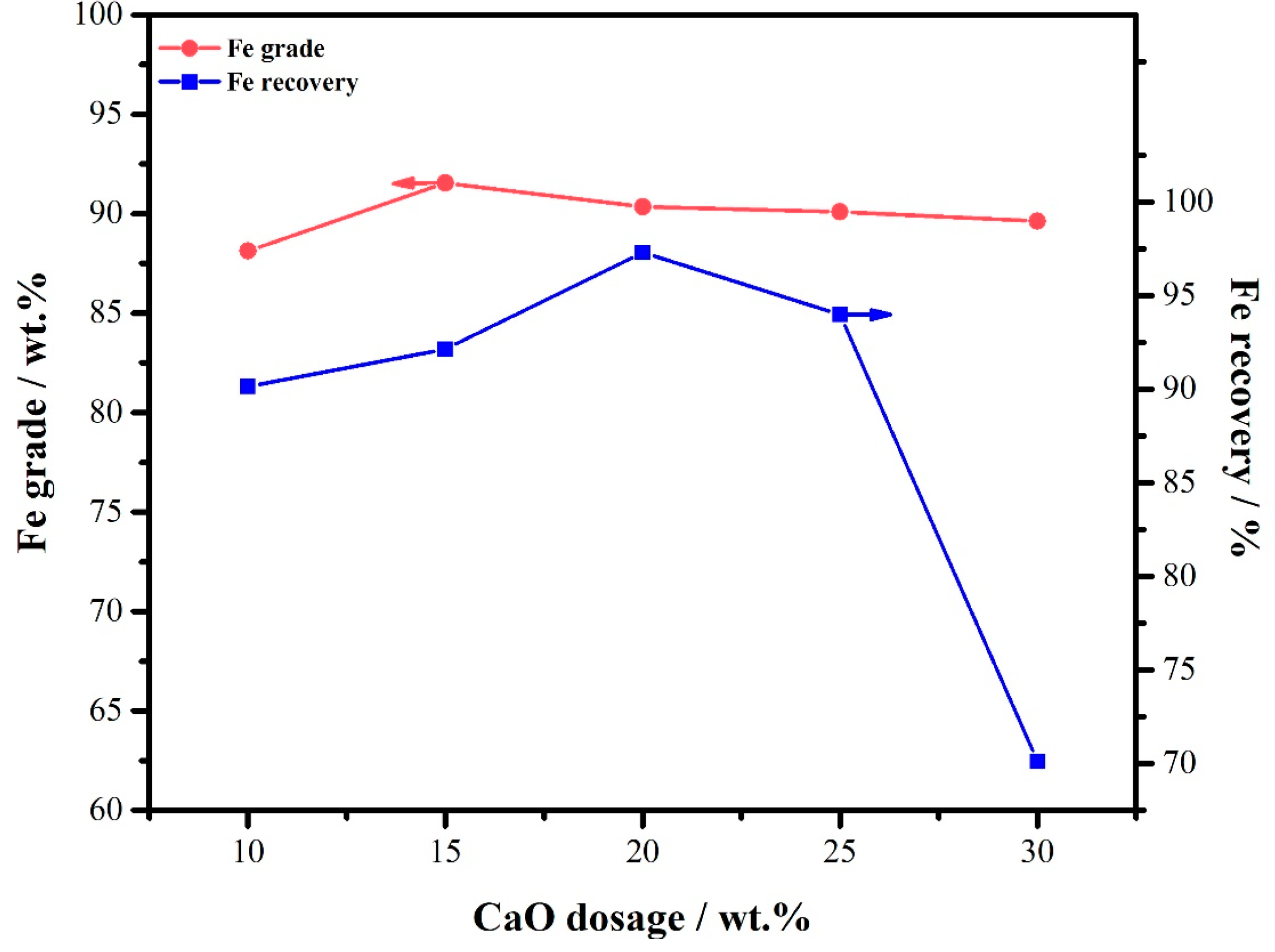
3.2.3. The Effect of CaO Dosage
As shown in Table 1, the CaO and SiO2 contents of copper slag were 3.41 wt.% and 57.32 wt.%, respectively. The basicity is calculated based on the ratio of CaO and SiO2 content in the copper slag. Therefore, the natural basicity of copper slag was 0.0595. Such a low basicity is disadvantageous for the reduction of iron-bearing compounds in the copper slag [42]. Therefore, some extra CaO additive was needed to increase the basicity of the copper slag pellet. The primary purpose of adding CaO is to reduce the decomposition temperature of fayalite and increase the liquid phase of the system, thus promoting the separation of slag and iron grains [42]. The effects of the CaO dosage on the Fe grade and recovery are shown in Figure 9. The reduction temperature and time were set at 1300 °C and 30 min, respectively, and the coal dosage was 35 wt.%.
As displayed in Figure 9, the CaO dosage had little effect on the Fe grade of concentrate. This result indicated that the metallic iron had been produced with low basicity. However, the Fe recovery increased first and then declined with the increase of CaO dosage. The max Fe recovery was obtained with the 20 wt.% CaO addition. When the CaO dosage continued to increase, the calcium ferrite liquid phase was easily generated inside the copper slag pellets, which caused the metallic iron grains to be wrapped and difficult to dissociate, thus reducing the Fe recovery. The optimal CaO addition should be 20 wt.%.
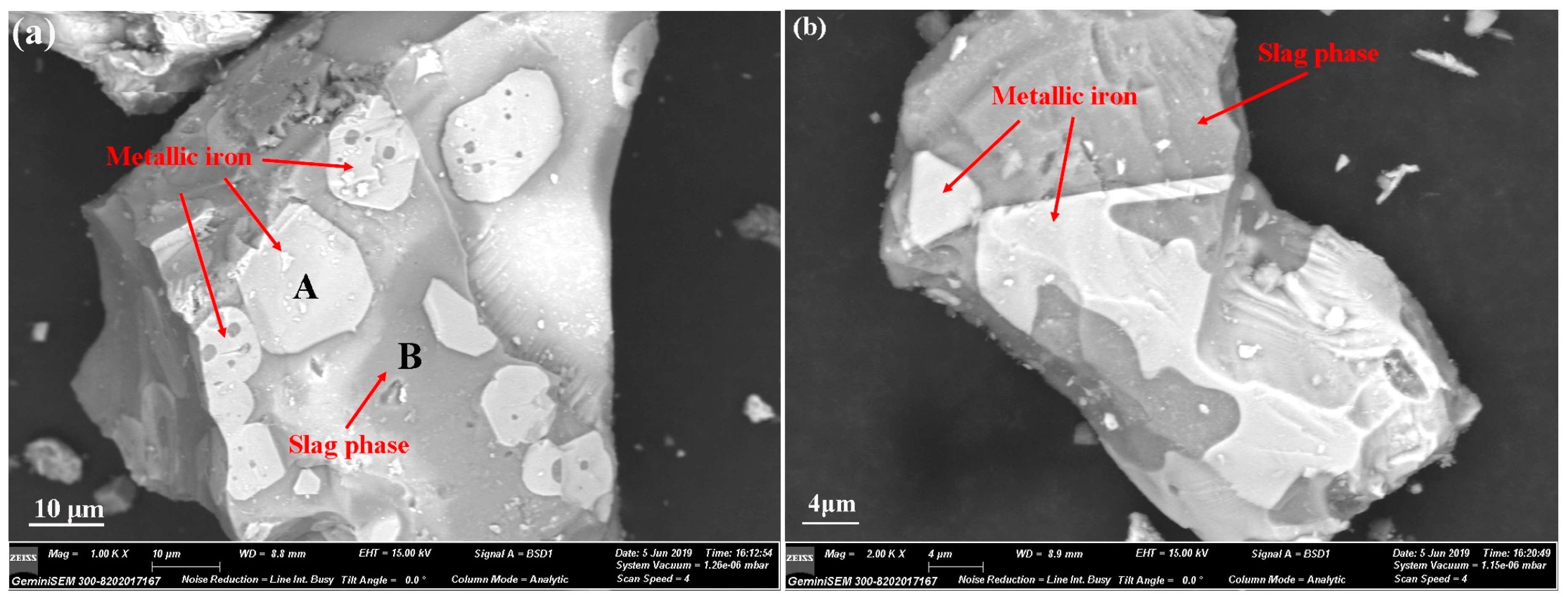
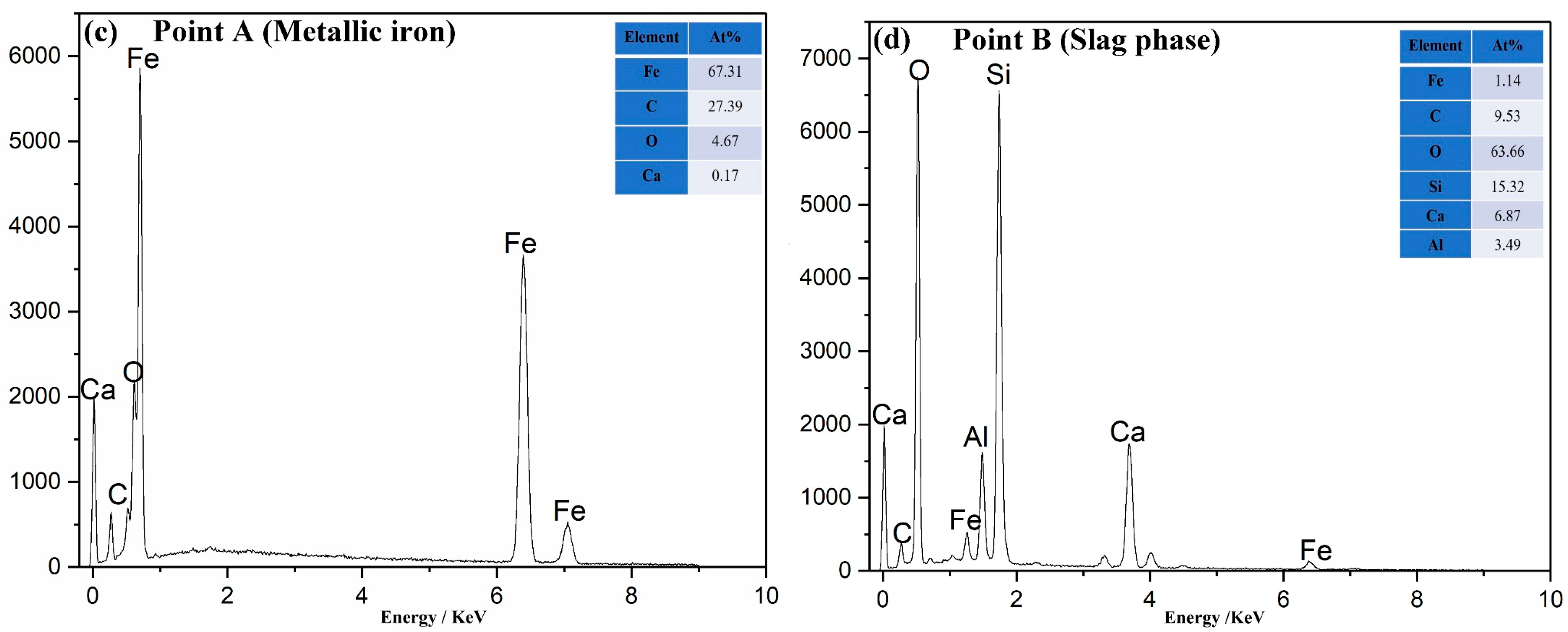
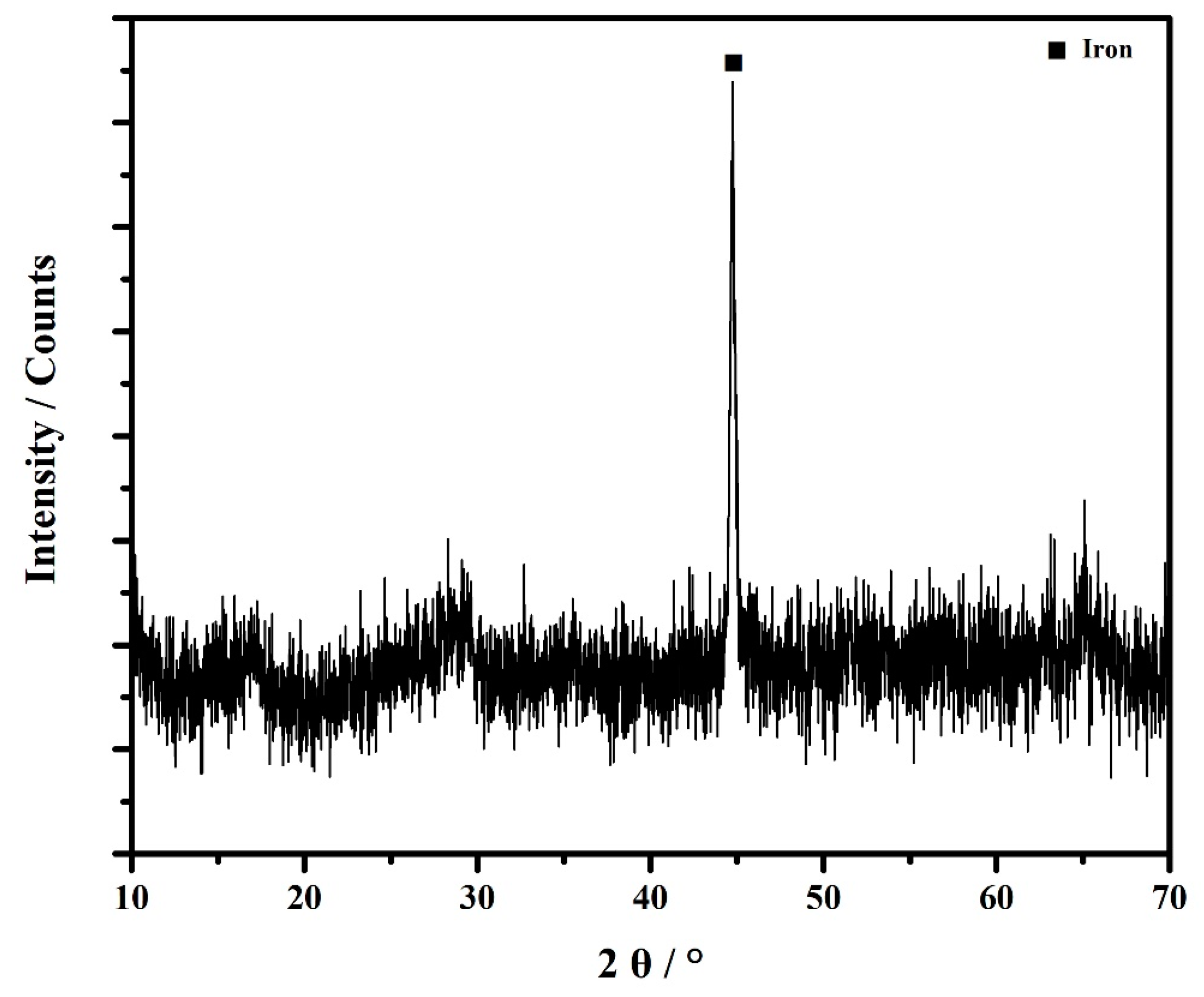
3.2.4. Product Analysis
Figure 10 consists of the micrographs and EDS analyses of the DRI product obtained from the direct reduction–magnetic separation processes. The XRD pattern of the metallic iron product was shown in Figure 11. The chemical component of metallic iron product was shown in Table 4. In the SEM micrographs, the bright area represents the metallic iron and the grey area represents the slag phase. The primary component of the slag phase is non-magnetic calcium metasilicate. Therefore, the iron could be easily recycled using magnetic separation. Furthermore, there is also a small amount of anorthite and amorphous phase in the slag. It can be seen that the large metallic iron particles formed after direct reduction. Meanwhile, some slag phase wrapped around the metallic iron particles and entered the DRI product, thereby reducing the Fe grade of the product. The XRD pattern of DRI product showed that the main XRD peak is the iron. Furthermore, there are some interferential peaks belonging to the amorphous phase. Table 4 indicates that the iron content in the DRI product could achieve 91.55 wt.%. Meanwhile, the harmful elements in the DRI product such as alkalis, S, and P were very low. It could be seen from the chemical component of the DRI product that this product is an excellent raw material for steelmaking.
3.3. The Direct Reduction Kinetic Model Analysis
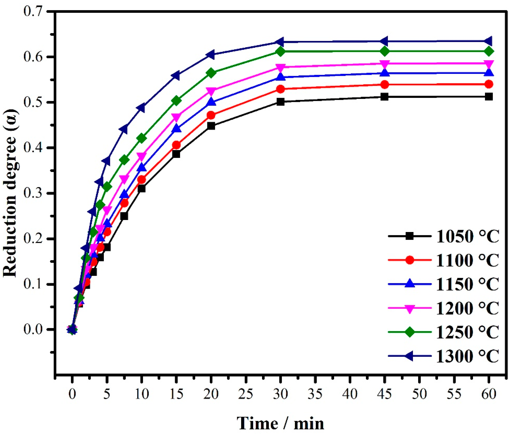
According to Equation (1), the reduction degrees under various reduction temperatures and times were calculated and are depicted in Figure 11.
As shown in Figure 12, the reduction degree was significantly influenced by the reduction temperature, and the high temperature improved the reduction of iron-bearing compounds in the copper slag. The fayalite is a kind of silicate mineral whose smelting point is about 1220 °C [43]. According to thermodynamic calculation, the addition of CaO could decrease the decomposition temperature of fayalite. When reduction temperature was lower than 1250 °C, the solid fayalite was hardly reduced by the fixed carbon in the coal by solid–solid reaction. The reaction efficiency between solid fayalite and solid CaO is also very low. When at a higher temperature, especially higher than 1250 °C, the fayalite began to melt, producing liquid phase, and the liquid fayalite could react with CaO more efficiently. The produced FeO was reduced by fixed carbon and reducing gas simultaneously. Therefore, a higher temperature is favorable for copper slag reduction. However, the energy consumption and equipment life should also be considered.
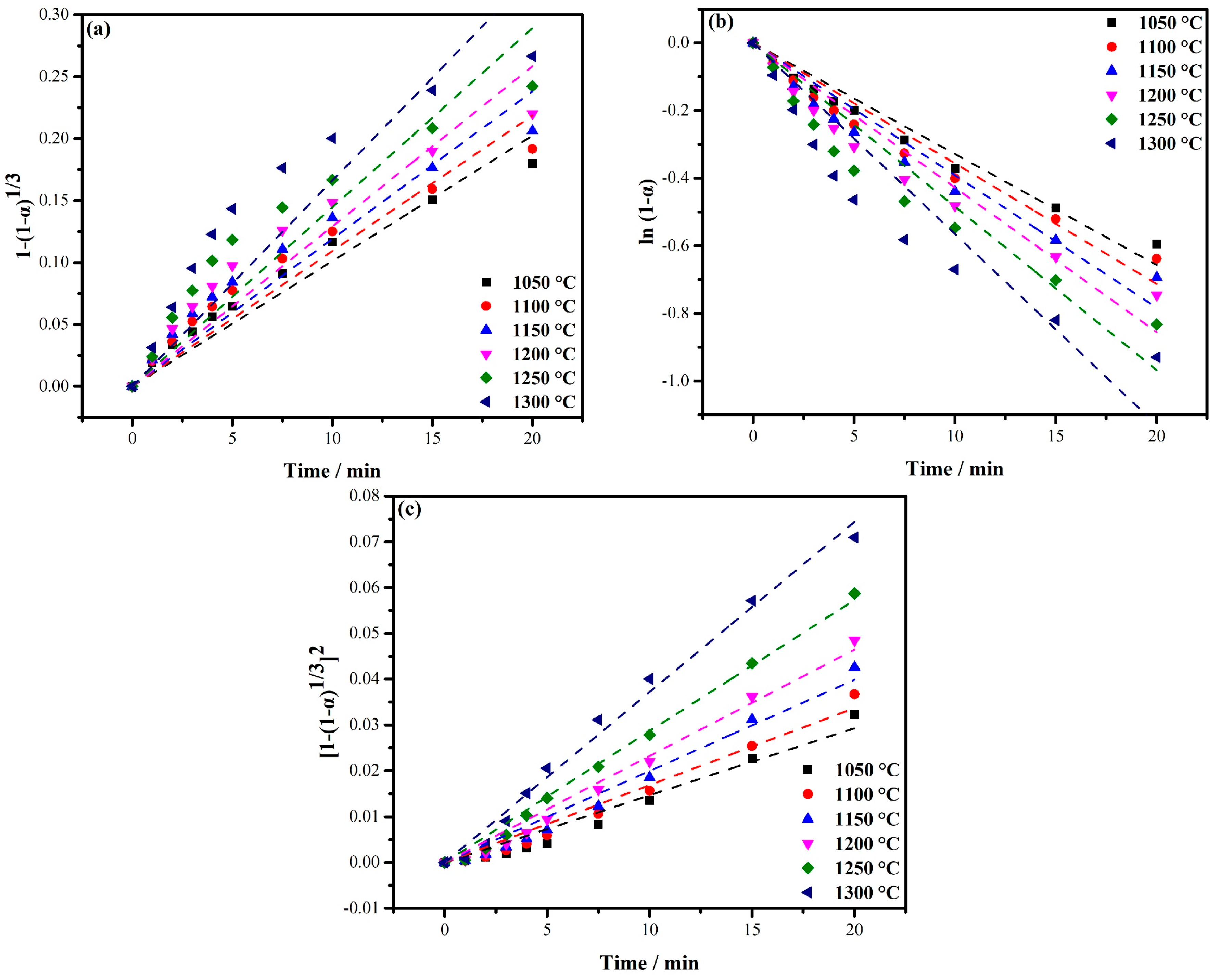
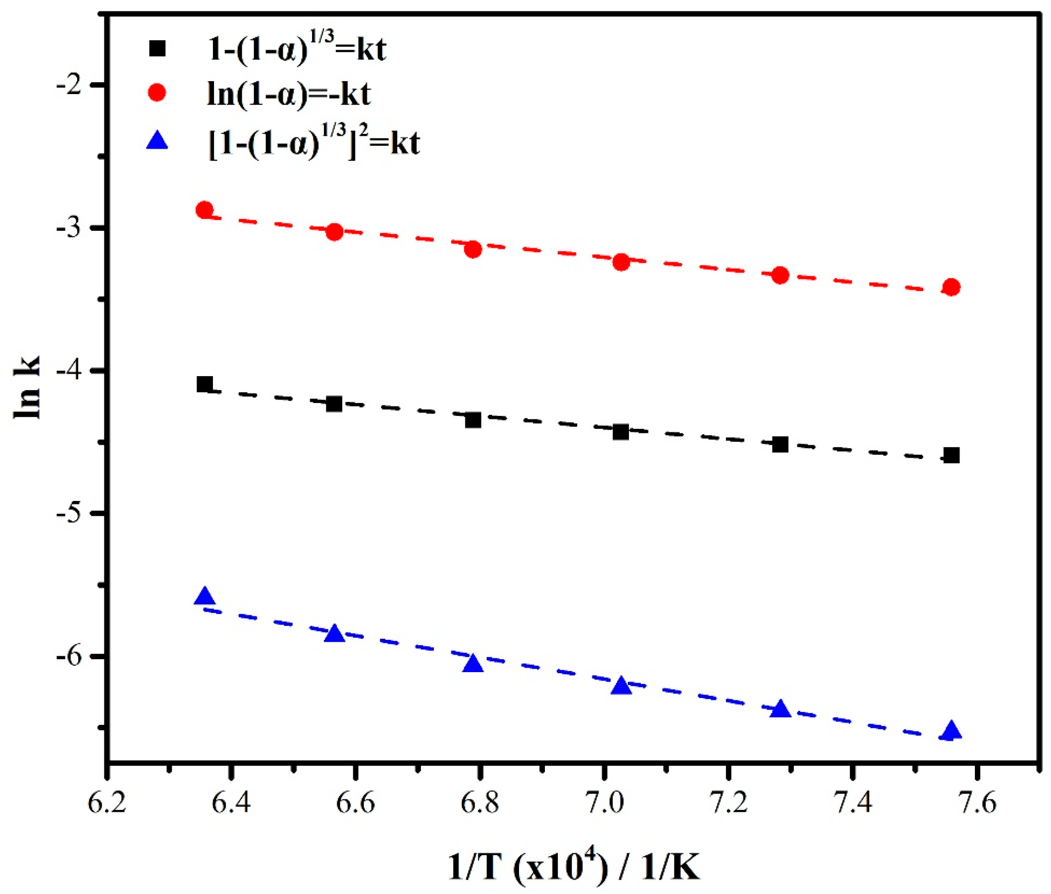
Subsequently, the reduction degree under experimental temperatures was fitted according to the Equations (2)–(4). The calculated lines of direct reduction kinetics are shown in Figure 13. For kinetic model fitting, the reduction degree data after equilibrium are meaningless, so in the next fitting calculations, the time range was set from 0 to 20 min. Subsequently, the calculation result was fitted according to the Arrhenius Equation to calculate the reaction activation energy.
From the calculated correlation coefficient (R2) shown in Table 5, it can be seen that the reduction kinetics of copper slag at 1050 °C are more consistent with the first and second kinetic models that belong to the interfacial reaction and carbon gasification controlling. This result indicated that at a lower temperature, the copper slag’s reduction was controlled by the interfacial reaction between carbon powder and copper slag and the gasification reaction of carbon. However, when the reduction temperature increased, the controlling step changed to the diffusion of the gas. At this time, the diffusion of CO in the copper slag pellet controlled the reduction rate. The above analyses indicated that, at a lower temperature, the Fe2SiO4 began to decompose to FeO. The Fe3O4 and FeO in copper slag were mainly reduced by carbon. When reduction temperature increased, the carbon was gasified to carbon monoxide. The Fe3O4 and FeO in copper slag were reduced by carbon monoxide. The reduction rate was improved.
The reaction activation energy calculations displayed in Figure 14 and Table 6 showed that the reduction reaction was mainly controlled by interfacial reaction and carbon gasification at a low temperature. At that moment, the primary reaction that occurred was the conversion of Fe3O4 to the FeO, which needed the low reaction activation energies. Meanwhile, the Fe2SiO4 could react with CaO, decomposing to FeO. When the reduction temperature increased, the primary reaction was the reduction of the FeO to the metallic iron, which needed the high reaction activation energies. The above results illustrated that the reduction characteristics of the copper slag at various temperatures were different. The main reason was that the composition of copper slag is complex, and different iron-bearing compounds in copper slag have different reduction characteristics. In general, the high reduction temperature can improve the reduction of iron-bearing compounds in copper slag.
4. Conclusions
In summary, the Fe3O4 and Fe2SiO4 in the copper slag could be reduced to the metallic iron by coal-based direct reduction and recovered by magnetic separation. The best reduction conditions were those in which the reduction temperature was 1300 °C, the reduction time was 30 min, the dosage of coal addition was 35 wt.%, and the dosage of CaO addition was 20 wt.% (0.75 binary basicity). Under this optimum condition, the Fe concentration with 91.55% iron grade was obtained after grinding and magnetic separation progresses, the Fe recovery could achieve 98.13%.
Research on the reduction kinetics indicated that the reduction of copper slag was controlled by the interfacial reaction and carbon gasification at 1050 °C. When reduction temperature increased, the reduction-controlling step of copper slag changed to the diffusion of the gas. The results of the integral kinetics model illustrate that the reduction of Fe3O4 in the copper slag, which needs low reaction activation energy, occurred first. Meanwhile, the Fe2SiO4 could react with CaO, decomposing to FeO. Then, the FeO began to be reduced to metallic iron by carbon monoxide. The controlling steps of each reduction reaction stage of copper slag were different. The main reason was that the composition of copper slag is complex, and different iron-bearing compounds in copper slag have different reduction characteristics. In general, the high reduction temperature can improve the reduction of iron-bearing compounds in copper slag.
Author Contributions
Conceptualization, H.Z. and M.L.; methodology, H.Z.; investigation, C.H. and W.G.; writing—original draft preparation, M.L.; funding acquisition, H.Z. All authors have read and agreed to the published version of the manuscript.
Funding
This research was funded by the National Natural Science Foundation of China, grant number 51974204.
Conflicts of Interest
The authors declare no conflict of interest.
References
- Dong, D.; Oers, V.; Tukker, A.; Voet, E.V.D. Assessing the future environmental impacts of copper production in China: Implications of the energy transition. J. Clean. Prod. 2020, 274, 122825. [Google Scholar] [CrossRef]
- Prem, P.R.; Verma, M.; Ambily, P.S. Sustainable cleaner production of concrete with high volume copper slag. J. Clean. Prod. 2018, 193, 43–58. [Google Scholar] [CrossRef]
- Potysz, A.; Kierczak, J. Prospective (Bio)leaching of historical copper slags as an alternative to their disposal. Minerals 2019, 9, 542. [Google Scholar] [CrossRef] [Green Version]
- Turan, M.D.; Sari, Z.A.; Miller, J.D. Leaching of blended copper slag in microwave oven. Trans. Nonferrous Met. Soc. 2017, 27, 1404–1410. [Google Scholar] [CrossRef]
- Guo, Z.Q.; Zhu, D.Q.; Pan, J.; Zhang, F. Innovative methodology for comprehensive and harmless utilization of waste copper slag via selective reduction-magnetic separation process. J. Clean. Prod. 2018, 187, 910–922. [Google Scholar] [CrossRef]
- Liu, S.; Zhang, Y.B.; Su, Z.J.; Lu, M.M.; Gu, F.Q.; Liu, J.C.; Jiang, T. Recycling the domestic copper scrap to address the China’s copper sustainability. J. Mater. Res. Technol. 2020, 9, 2846–2855. [Google Scholar] [CrossRef]
- Chen, J.J.; Wang, Z.H.; Wu, Y.F.; Li, L.Q.; Li, B.; Pan, D.A.; Zuo, T.Y. Environmental benefits of secondary copper from primary copper based on life cycle assessment in China. Resour. Conserv. Recycl. 2019, 146, 35–44. [Google Scholar] [CrossRef]
- Kinnunen, P.; Makinen, J.; Salo, M.; South, R.; Komnitsas, K. Efficiency of chemical and biological leaching of copper slag for the recovery of metals and valorisation of the leach residue as raw material in cement production. Minerals 2020, 10, 654. [Google Scholar] [CrossRef]
- Fan, Y.; Zhang, B.; Song, J.X.; Volski, V.; Vandenbosch, G.A.E.; Guo, M.X. An innovated application of reutilize copper smelter slag for cement-based electromagnetic interference composites. Sci. Rep. 2018, 8, 16155. [Google Scholar] [CrossRef] [Green Version]
- Meshram, P.; Prakash, U.; Bhagat, L.; Abhilash; Zhao, H.B.; van Hullebusch, E.D. Processing of Waste Copper Converter Slag Using Organic Acids for Extraction of Copper, Nickel, and Cobalt. Minerals 2020, 10, 290. [Google Scholar] [CrossRef] [Green Version]
- Jiang, H.D.; Hao, W.T.; Xu, Q.Y.; Liang, Q.M. Socio-economic and environmental impacts of the iron ore resource tax reform in China: A CGE-based analysis. Resour. Policy 2020, 68, 101775. [Google Scholar] [CrossRef]
- Anjos, M.A.G.d.; Sales, A.T.C.; Andrade, N. Blasted copper slag as fine aggregate in Portland cement concrete. J. Environ. Manag. 2017, 196, 607–613. [Google Scholar] [CrossRef] [PubMed]
- Wozniak, K.; Herman, D. Glass binder-bonded copper slag grains to form abrasive tools. J. Mater. Sci. 1988, 23, 223–228. [Google Scholar] [CrossRef]
- Sharma, R.; Khan, R.A. Sustainable use of copper slag in self compacting concrete containing supplementary cementitious materials. J. Clean. Prod. 2017, 151, 179–192. [Google Scholar] [CrossRef]
- Zhao, Z.W.; Chai, L.Y.; Peng, B.; Liang, Y.J.; He, Y.H.; Yan, H.Z. Arsenic vitrification by copper slag based glass: Mechanism and stability studies. J. Non-Cryst. Solids. 2017, 466, 21–28. [Google Scholar] [CrossRef]
- Heo, J.H.; Chung, Y.; Park, J.H. Recovery of iron and removal of hazardous elements from waste copper slag via a novel aluminothermic smelting reduction (ASR) process. J. Clean. Prod. 2016, 137, 777–787. [Google Scholar] [CrossRef]
- Shi, G.C.; Liao, Y.L.; Su, B.W.; Zhang, Y.; Wang, W.; Xi, J.J. Kinetics of copper extraction from copper smelting slag by pressure oxidative leaching with sulfuric acid. Sep. Purif. Technol. 2020, 241, 116699. [Google Scholar] [CrossRef]
- Zhang, L.; Zhu, Y.; Yin, W.Z.; Guo, B.; Rao, F.; Ku, J.G. Isothermal coal-based reduction kinetics of fayalite in copper slag. ACS Omega 2020, 5, 8605–8612. [Google Scholar] [CrossRef] [Green Version]
- Warczok, A.; Utigard, T.A. Fayalite Slag Reduction by Solid Graphite. Can. Metall. Q. 1998, 37, 27–39. [Google Scholar] [CrossRef]
- Pinto, R.G.; Yaremchenko, A.A.; Baptista, M.F.; Tarelho, L.A.C.; Frade, J.R. Synthetic fayalite Fe2SiO4 by kinetically controlled reaction between hematite and silicon carbide. J. Am. Ceram. Soc. 2019, 102, 5090–5102. [Google Scholar] [CrossRef]
- Khalid, M.K.; Hamuyuni, J.; Agrarwal, V.; Pihlasalo, J.; Haapalainen, M.; Lundstrom, M. Sulfuric acid leaching for capturing value from copper rich converter slag. J. Clean. Prod. 2019, 215, 1005–1013. [Google Scholar] [CrossRef]
- Guo, Z.Q.; Wang, Y.G.; Li, S.W.; Pan, J.; Zhu, D.Q.; Yang, C.C.; Pan, L.T.; Tian, H.Y.; Wang, D.Z. Reductive roasting mechanism of copper slag and nickel laterite for Fe-Ni-Cu alloy production. J. Mater. Res. Technol. 2020, 9, 7602–7614. [Google Scholar] [CrossRef]
- Guo, Z.Q.; Zhu, D.Q.; Pan, J.; Wu, T.J.; Zhang, F. Improving beneficiation of copper and iron from copper slag by modifying the molten copper slag. Metals 2016, 6, 86. [Google Scholar] [CrossRef] [Green Version]
- Chun, T.J.; Ning, C.; Long, H.M.; Li, J.X.; Yang, J.L. Mineralogical characterization of copper slag from Tongling nonferrous metals group China. JOM 2016, 68, 2332–2340. [Google Scholar] [CrossRef]
- Zhang, J.; Qi, Y.H.; Yan, D.L.; Cheng, X.L.; He, P. Characteristics and Mechanism of Reduction and Smelting-Separation Process of Copper Slag. J. Iron Steel Res. Int. 2015, 22, 121–127. [Google Scholar] [CrossRef]
- Guo, Z.Q.; Pan, J.; Zhu, D.Q.; Yang, C.C. Mechanism of composite additive in promoting reduction of copper slag to produce direct reduction iron for weathering resistant steel. Powder Technol. 2018, 329, 55–64. [Google Scholar] [CrossRef]
- Cheng, X.L.; Zhao, K.; Qi, Y.H.; Shi, X.F.; Zhen, C.L. Direct reduction experiment on iron-bearing waste slag. J. Iron Steel Res. Int. 2013, 20, 24–29. [Google Scholar] [CrossRef]
- Sarfo, P.; Das, A.; Wyss, G.; Young, C. Recovery of metal values from copper slag and reuse of residual secondary slag. Waste Manag. 2017, 70, 272–281. [Google Scholar] [CrossRef]
- Sarfo, P.; Wyss, G.; Ma, G.J.; Das, A.; Young, C. Carbothermal reduction of copper smelter slag for recycling into pig iron and glass. Miner. Eng. 2017, 107, 8–19. [Google Scholar] [CrossRef]
- Cao, Z.C.; Sun, T.C.; Xue, X.; Liu, Z.H. Iron recovery from discarded copper slag in a RHF direct reduction and subsequent grinding/magnetic separation process. Minerals 2016, 6, 119. [Google Scholar] [CrossRef] [Green Version]
- Zhou, S.W.; Wei, Y.G.; Li, B.; Wang, H. Cleaner recycling of iron from waste copper slag by using walnut shell char as green reductant. J. Clean. Prod. 2019, 217, 423–431. [Google Scholar] [CrossRef]
- Barisetty, S.; Kalshetty, S.; Ramakrishna, S.; Vishwanath, S.C.; Balachandran, G. Cold briquetting of DRI fines for use in steel making process. Trans. Indian Inst. Met. 2020, 73, 449–455. [Google Scholar] [CrossRef]
- Fuentes, I.; Ulloa, C.; Jiménez, R.; García, X. The reduction of Fe-bearing copper slag for its use as a catalyst in carbon oxide hydrogenation to methane. A contribution to sustainable catalysis. J. Hazard. Mater. 2020, 387, 121693. [Google Scholar] [CrossRef] [PubMed]
- Mitrašinović, A. Effect of Temperature and Graphite Immersion Method on Carbothermic Reduction of Fayalite Slag. JOM 2017, 69, 1682–1687. [Google Scholar] [CrossRef]
- Zuo, Z.L.; Yu, Q.B.; Luo, S.Y.; Zhang, J.K.; Zhou, E.Z. Effects of CaO on two-step reduction characteristics of copper slag using biochar as reducer: Thermodynamic and kinetics. Energy Fuel 2020, 34, 491–500. [Google Scholar] [CrossRef]
- Guo, D.B.; Li, Y.B.; Cui, B.H.; Chen, Z.H.; Luo, S.P.; Xiao, B.; Zhu, H.P.; Hu, M. Direct reduction of iron ore/biomass composite pellets using simulated biomass-derived syngas: Experimental analysis and kinetic modelling. Chem. Eng. J. 2017, 327, 822–830. [Google Scholar] [CrossRef]
- Lu, C.Y.; Zou, X.L.; Lu, X.G.; Xie, X.L.; Zheng, K.; Xiao, W.; Cheng, H.W.; Li, G.S. Reductive kinetics of Panzhihua ilmenite with hydrogen. Trans. Nonferrous Met. Soc. 2016, 26, 3266–3273. [Google Scholar] [CrossRef]
- Sui, Y.L.; Guo, Y.F.; Jiang, T.; Qiu, G.Z. Reduction kinetics of oxidized vanadium titano-magnetite pellets using carbon monoxide and hydrogen. J. Alloys Compd. 2017, 706, 546–553. [Google Scholar] [CrossRef]
- Wei, R.; Cang, D.; Bai, Y.; Huang, D.; Liu, X. Reduction characteristics and kinetics of iron oxide by carbon in biomass. Ironmak. Steelmak. 2016, 43, 144–152. [Google Scholar] [CrossRef]
- Wei, Z.; Zhang, J.; Qin, B.P.; Dong, Y.; Lu, Y.; Li, Y.; Hao, W.X.; Zhang, Y.F. Reduction kinetics of hematite ore fines with H2 in a rotary drum reactor. Powder Technol. 2018, 332, 18–26. [Google Scholar] [CrossRef]
- Guo, Z.Q.; Zhu, D.Q.; Pan, J.; Zhang, F. Mechanism of mineral phase reconstruction for improving the beneficiation of copper and iron from copper slag. JOM 2016, 66, 2341–2347. [Google Scholar] [CrossRef]
- Li, S.W.; Pan, J.; Zhu, D.Q.; Guo, Z.Q.; Xu, J.W.; Chou, J. A novel process to upgrade the copper slag by direct reduction-magnetic separation with the addition of Na2CO3 and CaO. Powder Technol. 2019, 347, 159–169. [Google Scholar] [CrossRef]
- Chen, G.Q.; Ahrens, T.J.; Stolper, E.M. Shock-wave Equation of state of molten and solid fayalite. Phys. Earth. Planet. Inter. 2002, 134, 35–52. [Google Scholar] [CrossRef]
Figure 1.
The XRD pattern of copper slag.

Figure 2.
The SEM micrograph of copper slag (a), the EDS result of point A (b), the EDS result of point B (c), and the EDS result of point C (d).
Figure 2.
The SEM micrograph of copper slag (a), the EDS result of point A (b), the EDS result of point B (c), and the EDS result of point C (d).

Figure 3.
The SEM-EDS mapping of copper slag sample: (a) SEM micrograph; (b) SEM-EDS mapping micrograph; (c) Fe element distribution; (d) Si element distribution; (e) Al element distribution; and (f) Ca element distribution. (a–f) scale bar is 3 μm.
Figure 3.
The SEM-EDS mapping of copper slag sample: (a) SEM micrograph; (b) SEM-EDS mapping micrograph; (c) Fe element distribution; (d) Si element distribution; (e) Al element distribution; and (f) Ca element distribution. (a–f) scale bar is 3 μm.

Figure 4.
The flow chart of the direct reduction–magnetic separation of copper slag.

Figure 5.
The diagram of the experimental equipment.

Figure 6.
The thermodynamic lines of each reduction reaction.

Figure 7.
The effect of reduction temperature and time on Fe grade (a) and recovery (b).

Figure 8.
The effects of coal dosage on the Fe grade and recovery.

Figure 9.
The effects of the CaO dosage on the Fe grade and recovery.

Figure 10.
The micrography of the direct reduction of iron (DRI) product (a,b); the EDS result of point A (c); the EDS result of point B (d).
Figure 10.
The micrography of the direct reduction of iron (DRI) product (a,b); the EDS result of point A (c); the EDS result of point B (d).


Figure 11.
The XRD pattern of DRI product.

Figure 12.
The reduction degree under various reduction temperatures and times.

Figure 13.
The calculated lines of different kinetic models—(a) Equation (2), (b) Equation (3), and (c) Equation (4)—under various temperatures.
Figure 13.
The calculated lines of different kinetic models—(a) Equation (2), (b) Equation (3), and (c) Equation (4)—under various temperatures.

Figure 14.
The linear fitting of the Arrhenius Equation of various kinetic models (Equations (2)–(4)).
Figure 14.
The linear fitting of the Arrhenius Equation of various kinetic models (Equations (2)–(4)).


Table 1.
Main chemical composition of copper slag (wt.%).
| Fe2O3 | CuO | SiO2 | Al2O3 | CaO | MgO | Na2O | K2O | SO3 | Cr2O3 |
|---|---|---|---|---|---|---|---|---|---|
| 68.20 | 0.98 | 24.72 | 3.38 | 0.30 | 0.72 | 0.48 | 0.65 | 0.40 | 0.08 |
Table 2.
The proximate analysis of coal (wt.%).
| Moisture | Volatiles | Ash | Fixed Carbon | Sulfur |
|---|---|---|---|---|
| 7.65 | 28.67 | 10.08 | 52.39 | 0.64 |
Table 3.
The chemical composition of bentonite (wt.%).
| SiO2 | Al2O3 | Fe2O3 | CaO | MgO | K2O | Na2O | TiO2 | SO3 |
|---|---|---|---|---|---|---|---|---|
| 57.32 | 15.1 | 7.29 | 3.41 | 2.72 | 1.23 | 1.21 | 1.39 | 0.02 |
| P2O5 | MnO | ZnO | SrO | ZrO2 | BaO | Cl | LOI | |
| 0.38 | 0.1 | 0.011 | 0.033 | 0.027 | 0.053 | 0.022 | 9.51 |
Table 4.
Chemical component of DRI product (wt.%).
| TFe* | CuO | SiO2 | Al2O3 | CaO | MgO | Na2O | K2O | S | P |
|---|---|---|---|---|---|---|---|---|---|
| 91.55 | 0.25 | 0.32 | 0.57 | 0.31 | 0.08 | 0.08 | 0.02 | 0.07 | 0.01 |
TFe* is the total iron content in the metallic iron product.
Table 5.
The fitting parameters of different kinetic models under various temperatures.
| T/°C | ||||||
|---|---|---|---|---|---|---|
| k | R2 | k | R2 | k | R2 | |
| 1050 | 0.01012 | 0.976 | 0.03283 | 0.983 | 0.00146 | 0.973 |
| 1100 | 0.01093 | 0.967 | 0.03564 | 0.976 | 0.00169 | 0.982 |
| 1150 | 0.01191 | 0.964 | 0.03914 | 0.974 | 0.00199 | 0.984 |
| 1200 | 0.01292 | 0.956 | 0.04277 | 0.967 | 0.00232 | 0.990 |
| 1250 | 0.01446 | 0.940 | 0.04839 | 0.954 | 0.00287 | 0.996 |
| 1300 | 0.01661 | 0.918 | 0.05648 | 0.936 | 0.00372 | 0.994 |
Table 6.
The fitting parameters of the Arrhenius Equation of various kinetic models (Equations (2)–(4)).
Table 6.
The fitting parameters of the Arrhenius Equation of various kinetic models (Equations (2)–(4)).
| Parameters | ||||||
|---|---|---|---|---|---|---|
| Eα/k J·mol−1 | R2 | Eα/k J·mol−1 | R2 | Eα/k J·mol−1 | R2 | |
| Copper slag pellet | 33.370 | 0.966 | 36.508 | 0.963 | 63.048 | 0.967 |
Publisher’s Note: MDPI stays neutral with regard to jurisdictional claims in published maps and institutional affiliations. |
© 2020 by the authors. Licensee MDPI, Basel, Switzerland. This article is an open access article distributed under the terms and conditions of the Creative Commons Attribution (CC BY) license (http://creativecommons.org/licenses/by/4.0/).
Share and Cite
MDPI and ACS Style
Zhang, H.; Hu, C.; Gao, W.; Lu, M. Recovery of Iron from Copper Slag Using Coal-Based Direct Reduction: Reduction Characteristics and Kinetics. Minerals 2020, 10, 973. https://0-doi-org.brum.beds.ac.uk/10.3390/min10110973
AMA Style
Zhang H, Hu C, Gao W, Lu M. Recovery of Iron from Copper Slag Using Coal-Based Direct Reduction: Reduction Characteristics and Kinetics. Minerals. 2020; 10(11):973. https://0-doi-org.brum.beds.ac.uk/10.3390/min10110973
Chicago/Turabian StyleZhang, Hanquan, Chaojie Hu, Wangjie Gao, and Manman Lu. 2020. "Recovery of Iron from Copper Slag Using Coal-Based Direct Reduction: Reduction Characteristics and Kinetics" Minerals 10, no. 11: 973. https://0-doi-org.brum.beds.ac.uk/10.3390/min10110973
Note that from the first issue of 2016, this journal uses article numbers instead of page numbers. See further details here.