Utilizing Temperature and Brine Inflow Measurements to Constrain Reservoir Parameters During a Salt Heater Test

Applied Systems Analysis & Research Department Sandia National Laboratories, P.O. Box 5800, Albuquerque, NM 87185-0747, USA
*
Author to whom correspondence should be addressed.
Minerals 2020, 10(11), 1025; https://0-doi-org.brum.beds.ac.uk/10.3390/min10111025
Submission received: 27 October 2020
/
Revised: 13 November 2020
/
Accepted: 15 November 2020
/
Published: 18 November 2020
(This article belongs to the Special Issue The Hydro-Mechanics of Crystalline Rocks)
Abstract
:Brine availability in salt has multiple implications for the safety and design of a nuclear waste storage facility. Brine availability includes both the distribution and transport of brine through a damaged zone around boreholes or drifts excavated into the salt. Coupled thermal, hydrological, mechanical, and chemical processes taking place within heated bedded salt are complex; as part of DECOVALEX 2023 Task E this study takes a parsimonious modeling approach utilizing analytical and numerical one-dimensional simulations to match field measurements of temperature and brine inflow around a heater. The one-dimensional modeling results presented arrive at best-fit thermal conductivity of intact salt, and the permeability and porosity of damaged salt of 5.74 , m, and ≈ 0.02, respectively.
1. Introduction
1.1. Background
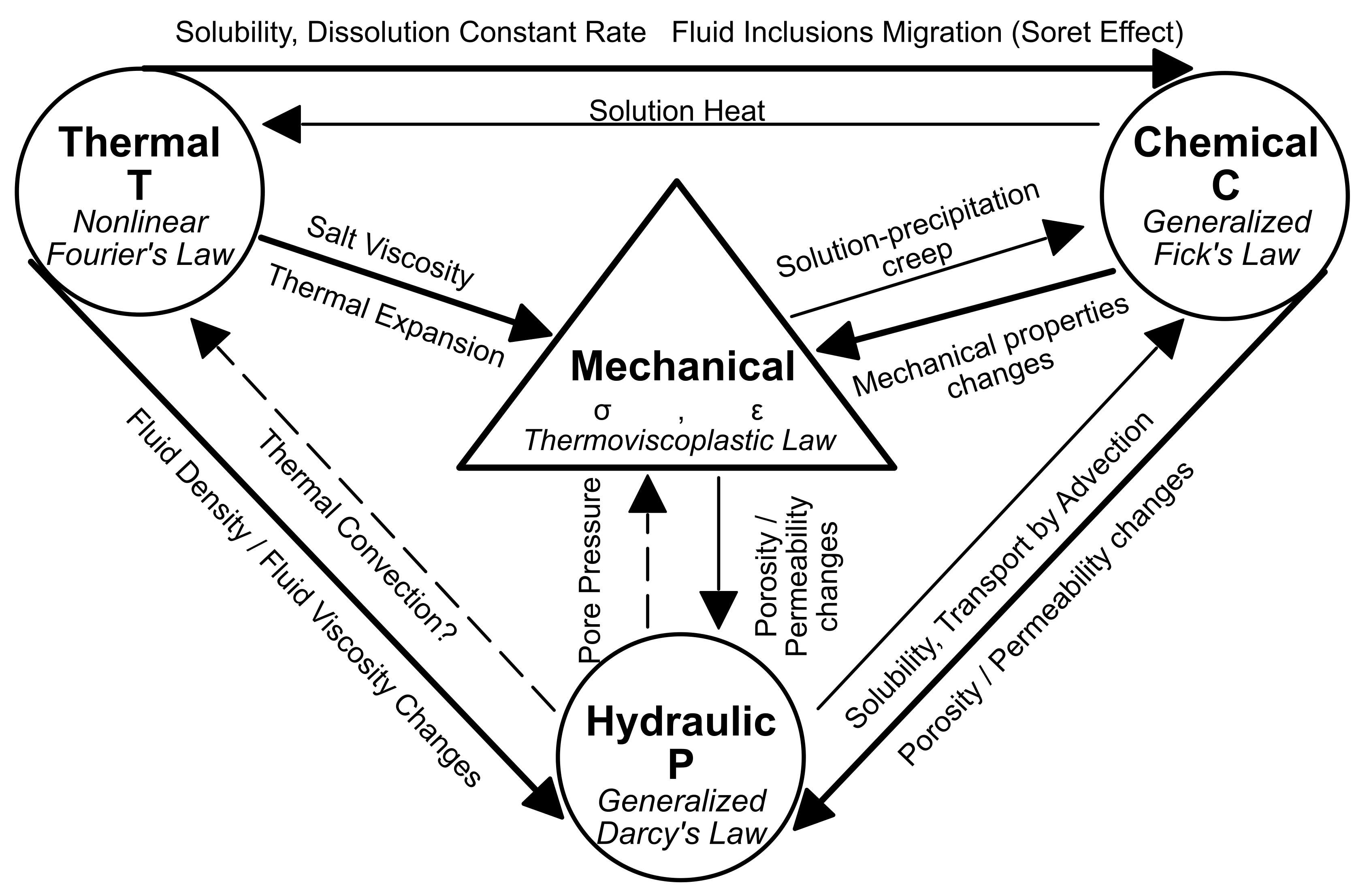
The United States has been interested in disposing of radioactive waste in geologic salt since the 1950s when Hess et al. [1] recommended the direct disposal of liquid reprocessing waste into salt caverns. Since then, several underground field studies have investigated the feasibility of nuclear waste disposal within salt formations across the United States, Project Salt Vault [2], Avery Island [3,4,5], the Deaf Smith site [6,7], and most recently the Waste Isolation Pilot Plant (WIPP) (e.g., [8,9,10,11,12,13,14]), which is currently an active research and disposal (non-heat generating transuranic defense waste) facility. What makes salt such an interesting and potentially effective disposal medium is its low permeability [15] to brine transport and high thermal conductivity relative to other media, such as clay or granite. This makes its thermal and hydraulic diffusivities the same order of magnitude [16,17], which means that the interplay between thermal, hydrological, mechanical, and chemical (THMC) processes are critically important (Figure 1). While undisturbed rock salt has almost immeasurably low porosity and permeability, upon excavation, a damaged region develops surrounding the excavation [18]. As a result, this region is referred to as a “disturbed rock zone” (DRZ) and introduces significant changes around a borehole or access drift that impact the near-field transport of brine and gas through the salt [19]. The mechanical damage caused by stress relief during excavation leads to increased permeability and porosity of the salt and induced fractures which provide high permeability pathways for brine transport [20]. Since brine migration is the primary off-site radionuclide transport vector, understanding and characterizing the near-field conditions (i.e., DRZ) and processes is an important initial condition to predicting the long-term safety of the system. Open excavations in salt will eventually creep closed and fractures will heal, but we seek to understand the short-term transport properties of the DRZ.
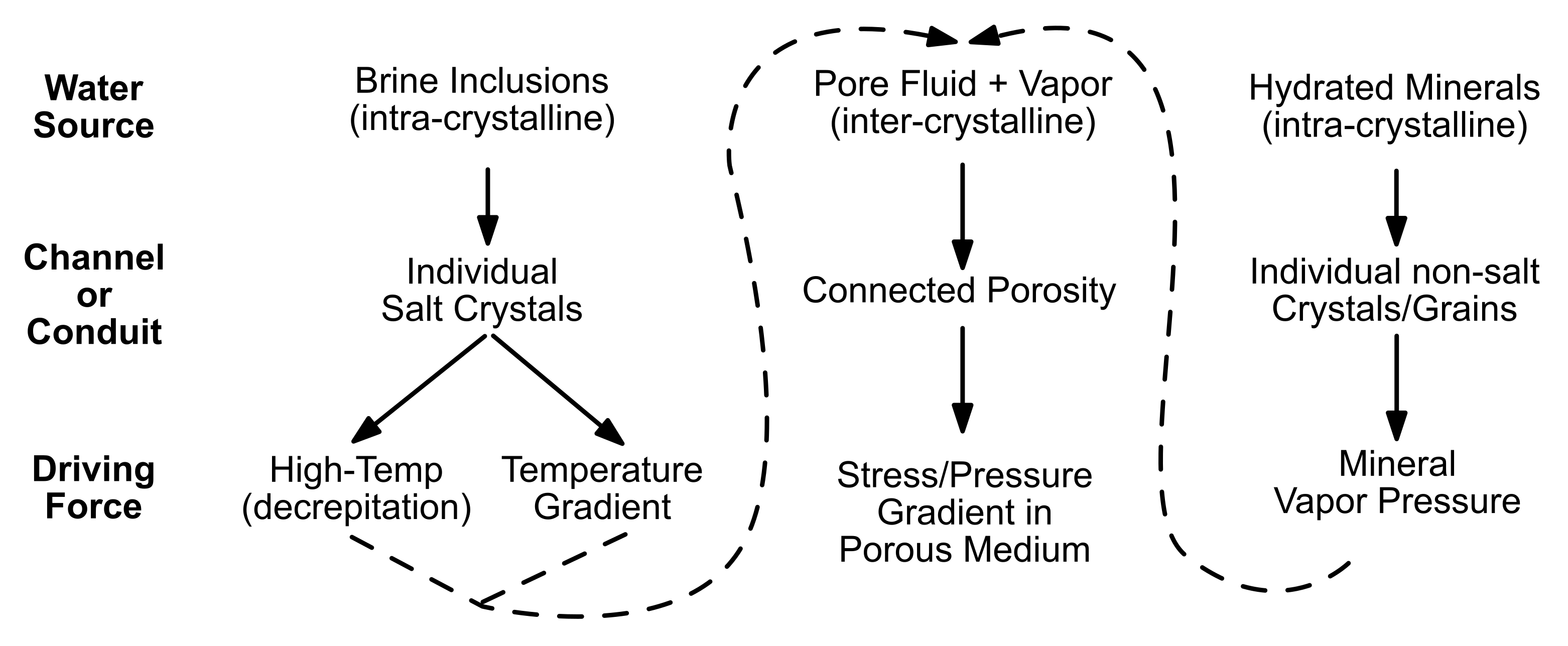
Salt presents a unique challenge with respect to the coupled processes affecting mass and heat transport (Figure 1). The coupled nature of salt behavior in the context of radioactive waste disposal was first explored in the 1950s [1,22,23]. By the late 1980s many of the major important processes impacting heated bedded salt were confirmed through large scale experiments at WIPP, Avery Island, and Asse [24]. Brine migration within bedded salt varies by driving mechanism and type of brine. Figure 2 illustrates the brine migration mechanisms and how they are related to type of brine and driving force. Intra- and inter-crystalline brine can both be directly affected by pressure or temperature. The excavation of boreholes and tunnels in the salt creates a connected network of damage-induced porosity, and causes significant changes to the stress and pore pressure within the salt. This driving force causes brine to migrate towards a low-pressure drift or borehole via new DRZ connected porosity. Most inter-granular brine is associated with disseminated clay within the salt formation. The addition of heat from a waste package creates two different driving forces for intra-crystalline brine: (1) high temperatures can cause decrepitation of fluid inclusions [25] and (2) an elevated temperature gradient causes fluid inclusions to migrate towards the heat source [26]. Once liberated, fluid starting as fluid inclusions becomes more mobile as inter-crystalline brine, which flows through new interconnected pores of the DRZ down a pressure gradient. Intact salt is an ideal medium to dispose of nuclear waste, but the excavation and introduction of heat causes the thermal and pressure regimes to drastically change within the salt causing a near-excavation high permeability pathway to allow inter- and intra-crystalline brine to migrate towards the excavation, leading to a more complex short-term and near-field flow system.
To better understand the effects the DRZ and higher temperatures have on brine availability and migration within salt, several salt heater tests have been implemented since the 1960s to investigate these engineered systems. In the 1960s in Lyons, Kansas, Project Salt Vault carried out four different salt heater experiments in bedded salt to investigate creep, viscoplastic flow of salt, room closure, and simulate disposal of high-level waste (HLW) containers in vertical boreholes [2]. During these heater tests in boreholes with less shale, brine inflow remained relatively low until an abrupt 40% increase in heater power when a large increase in brine inflow was observed and another pulse of brine inflow occurred when the power was shut off [2]. The observed water release after turning off the heaters was believed due to the reduced tangential compressive stress caused by the reversal of the thermal gradient near the borehole. The Avery Island project ran three separate heater tests in a salt dome in the 1970s and 1980s to estimate salt thermal conductivity, simulate disposal of HLW, and study the feasibility of granular salt as a backfill material with the overall goal to test temperature and displacement of salt over the course of 32 months [3,4,28]. Gas permeability tests were conducted in packer-isolated boreholes [29] during an additional heater test at Avery Island [30]. Results showed salt permeability was several orders of magnitude lower in boreholes reaching higher temperatures during the test, this lowered permeability was credited to salt expansion closing off damage-induced fracture porosity [29]. In the 1980s and 1990s in bedded salt at WIPP, three major drift-scale heated thermal/structural interactions (TSI) demonstrations (Rooms A1–A3, B, and H) were conducted to illustrate stability of excavated rooms, possible retrieval of disposed waste, and long-term disposal room deformation [31]. At the Asse II mine in Germany three large-scale heater tests were carried out in domal salt to investigate low- to medium-level radioactive waste disposal with a focus on salt/waste interactions and various emplacement technologies [32]. Understanding and quantifying heat and mass transport in salt during a salt heater test is a complex problem that requires complex numerical models informed by field observations and state-of-the-art knowledge of the system.
1.2. Brine Availability Test in Salt
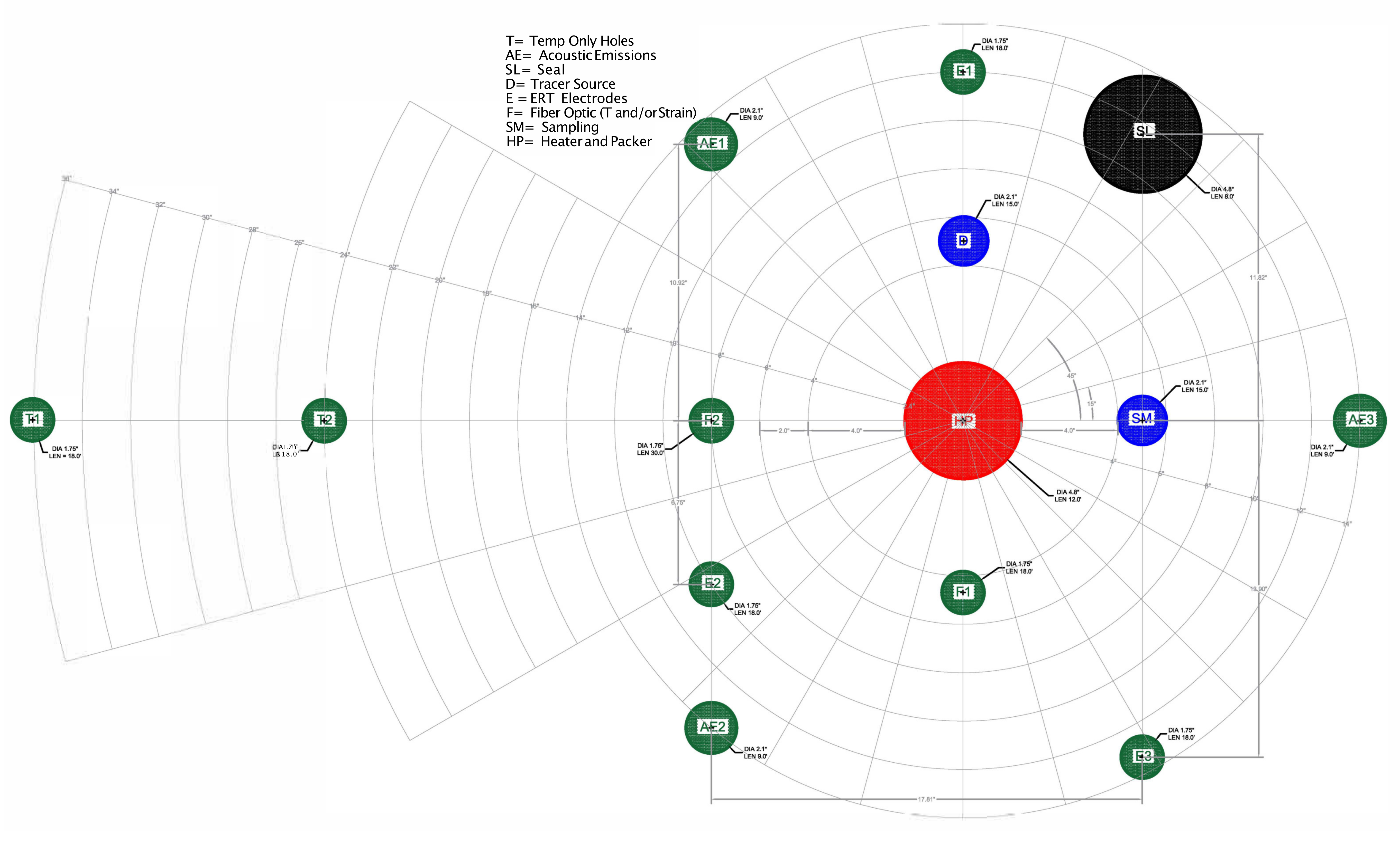
Currently, the Brine Availability Test in Salt (BATS) is being conducted underground at the WIPP (near Carlsbad, NM) in the US Department of Energy (DOE) Office of Environmental Management’s (DOE-EM) facility, funded by the DOE Office of Nuclear Energy (DOE-NE) as part of a field-testing campaign investigating the effect of an embedded heat source (mimicking heat generating waste) in salt. A multi-lab effort at DOE-NE Spent Fuel and Waste Science and Technology (SFWST) program is investigating generic (i.e., non site-specific) disposal concepts for heat-generating radioactive waste in crystalline, argillite, and salt formations. The focus of BATS is brine availability in salt, which is important to understand because: brine transport of radionuclides is a potential repository release mechanism, brine can corrode metallic and glass waste forms and waste packages, chloride in hypersaline brine can reduce in-package criticality concerns, and accumulated brine in an excavation can provide back-pressure that resists long-term creep closure of porosity associated with mining the repository. BATS is a meter-scale borehole heater test, with the goals of: (1) improving the understanding of brine availability and brine chemistry in the DRZ for bedded salt; (2) collecting data for validating numerical models, populating constitutive models, and improving process model understanding; (3) revitalizing in-house expertise at participating institutions in implementing in situ experiments in salt [20]. The experimental setup for BATS includes two arrays of boreholes, each with a 3-m long, 12-cm diameter horizontal, central heater borehole surrounded by sampling and monitoring boreholes (Figure 3). One array was heated, the other was at monitored at ambient temperature. An earlier phase of BATS was conducted in 2018 in existing (rather than drilled for purpose) boreholes in a different drift at WIPP to test aspects of experiment design while collecting brine inflow and temperature data [33]. Staff from Sandia, Los Alamos, and Lawrence Berkeley National Laboratories are working with the WIPP Test Coordination Office to implement the BATS field test, which is a major part of DECOVALEX 2023 Task E. In January 2020, the first phase of the BATS experiment began heating experiments in the new horizontal boreholes. The heater was set to constant temperature for 28 days, the heater was then shut off and the salt was monitored while cooling for 13 days [34]. During the 41-day experiment, temperature data and brine inflow rate were measured at a high frequency (15 min averages), along with attempted weekly brine composition samples, daily electrical resistivity tomography surveys, continuous monitoring of acoustic emissions, and high-frequency water isotopic gas composition data by in-drift spectroscopy. In this study we used the observed temperature and total brine inflow data with one-dimensional models to investigate the thermal and hydrologic properties of the DRZ.
Intact salt is considered an effective disposal medium for heat-generating nuclear waste because of its high thermal conductivity and almost immeasurably low permeability and porosity [15], but excavations causes stress changes, which lead to a damaged zone consisting of fractures and increased permeability and porosity for brine migration [10]. The presence of this damage introduces significant uncertainty in the distribution of hydraulic and thermal properties across the DRZ, which is often considered to extend approximately one excavation radius into the salt [35]. Openings in salt will eventually (i.e., after tens to hundreds of years) creep closed and heal over time to the very low porosity and permeability of intact salt. Increased temperatures further accelerate the creep closure process. However, brine availability during the operational and early post-closure phases of a salt repository is controlled by the transport properties and brine distribution within the DRZ. The early time distribution and mobility of brine within the DRZ is the initial condition for long-term repository performance assessment (PA), and will significantly impact any early releases in an off-normal disturbed scenario (e.g., unintentional human intrusion). This study seeks to infer hydraulic and thermal properties of the DRZ from the BATS heater test and illustrate their impact on temperature and brine migration within a bedded salt formation. Due to the interdependent non-linear nature of coupled processes in heated salt relevant for nuclear waste disposal, a fully-coupled THMC model that can accommodate large deformations (e.g., TOUGH-FLAC Rutqvist [36]) would be required to model and incorporate the major coupled processes. Not only does a fully-coupled THMC model require significant computational resources, the complexity of the problem itself can obfuscate some relationships. Instead, we take a parsimonious modeling approach that utilizes a one-dimensional (1D) spherically symmetric analytical heat conduction solution for parameter estimation and a 1D cylindrically symmetric thermal-hydrological (TH) model of heat and mass flow in order to investigate the hydraulic and thermal properties of the DRZ by matching both temperature and brine output measured in the field during a salt heater test. We have chosen these methods because compared to the analytical thermal model, the thermal–hydrological model is a relatively small step up in complexity that includes more physical processes, without the much bigger step up complexity of a large-scale three-dimensional (3D) TH or THMC model.
2. Methods
This study combines parameter estimation, an analytical solution for heat conduction, and TH numerical modeling to investigate the influence of the fractured nature of the DRZ on brine flow and migration within bedded salt. The models represent the BATS field experiment, where a 69-cm long interval 2.75 m deep into in the central borehole is heated to a constant temperature. Water inflow to the heated borehole is monitored through removal of the moisture with circulating dry nitrogen gas behind an inflatable packer, and temperature is monitored at 66 thermocouples (72 total thermcouples at the BATS site, 66 of which produced useable data) grouted into satellite boreholes around the heater (see Kuhlman et al. [34] for sensor locations and detailed test and data descriptions). While thermal, hydrologic and mechanical properties of bedded salt have been studied extensively at the WIPP site and other historical salt underground research laboratories, the steep spatial variability of material properties across the DRZ (e.g., pressure varies from atmospheric at the drift to lithostatic in the intact salt) makes it difficult to accurately constrain these properties. As a result, this study uses two computational methods in tandem to investigate the thermal and hydrologic parameters of the DRZ. First, an analytical heat conduction solution [37] is fit to observed data at 66 thermocouples through time using a Markov chain Monte carlo (MCMC) parameter estimator [38]. The best-fit thermal parameters (thermal conductivity and heat capacity) are then used within a 1D cylindrically symmetric TH TOUGH2 [39] model to solve for both heat and mass transport to match data collected at the BATS site in order to constrain the hydrologic parameters of the DRZ that control brine inflow.
2.1. Analytical Solution
An analytical solution for heat conduction into an infinite medium from a spherical cavity, with the cavity wall held at constant temperature [37], is
where is the temperature C due to a type I (i.e., specified temperature) boundary condition, is the radius (m)of the spherical cavity (approximating the 69-cm interval of heated 12-cm diameter borehole), is the complementary error function, is the specified temperature on the cavity wall, is the thermal diffusivity () is the thermal conductivity (), is the density (), and is the heat capacity (). With this solution we are approximating the cylindrical-shaped heat source as a sphere. At distances further from the heater this approximation may be adequate, but close to the heater (e.g., within one heater length) the shape of the heater may influence the observed temperature. The analytical solution also assumes parameters are homogeneous in space and linear (i.e., no temperature-dependent thermal conductivity) to allow for superposition of solutions.
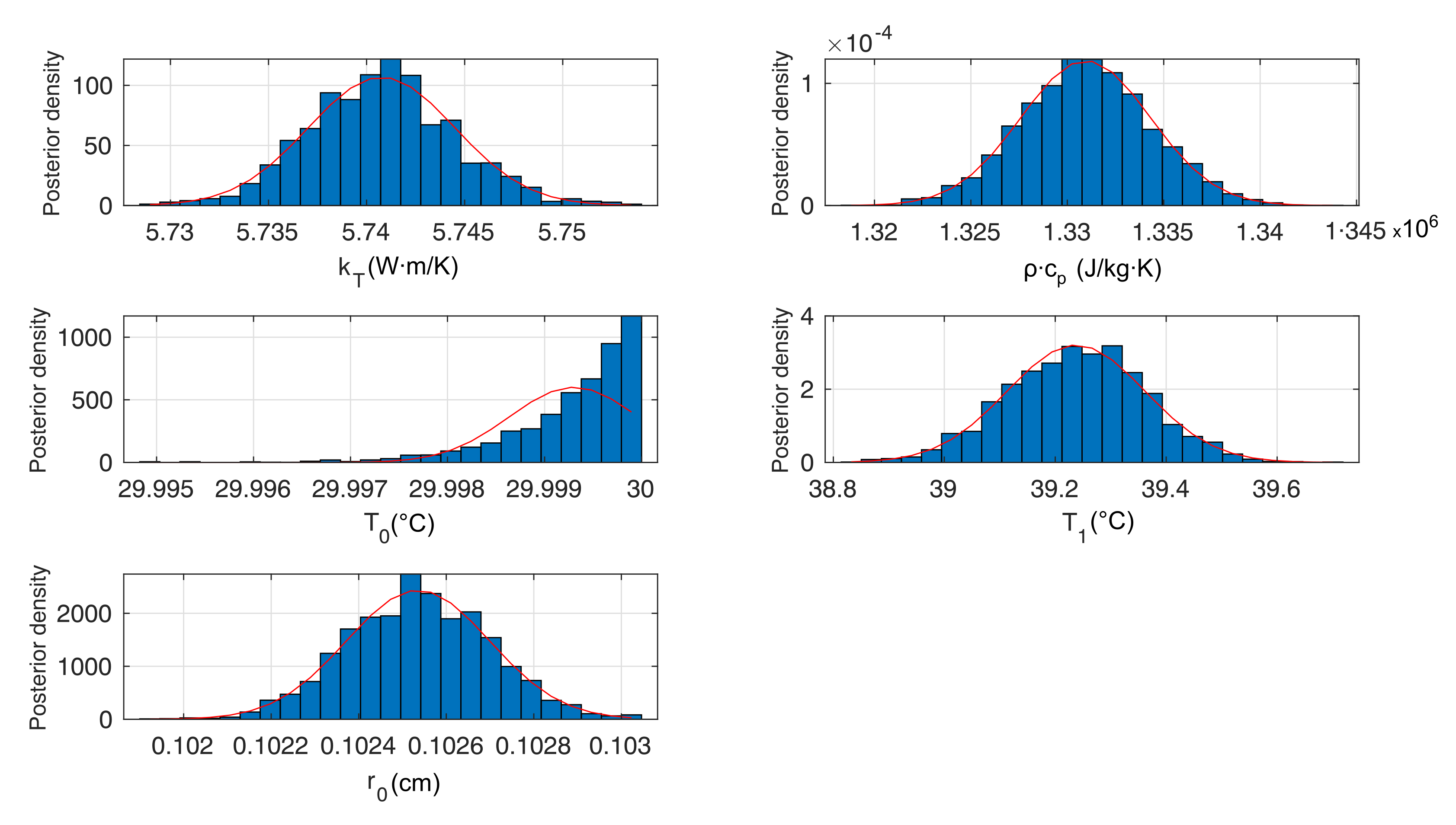
Parameter estimation with the analytical solution was performed using DREAM, a Markov chain Monte Carlo (MCMC) global gradient-free optimizer [38]. DREAM was used to estimate five parameters, , , two borehole wall temperatures , , and . Each of the parameters was given a wide parameter range and a uniform prior distribution across that range. The cavity radius was estimated because treating the borehole as a spherical cavity is an idealization. The temperature applied to the borehole wall was also estimated to account for some uncertainty in the applied temperature (the controlling thermocouple on the borehole wall was set to 120 C) and possible inefficiencies in heat transfer to the salt (e.g., some applied heat is re-radiated back to the equipment in the borehole or carried away in the stream of dry nitrogen gas). By using all the temperature and applied power data to constrain the solution, and allowing the major parameters in the solution to be fit, we are trying to better understand the actual information content in the data.
During the first 149 min of the test the heater controller inadvertently switched off several times, so was applied to the borehole wall from the beginning of the test, and at the end of the initial 149 min of heating, a second source was added at . To include the effects of cool-down (no applied power, not a constant-temperature boundary condition), an analytical solution for a type II boundary condition (i.e., specified temperature gradient) on the wall of a spherical cavity was turned on at the end of heating
where is the gradient applied on the cavity wall (). The gradient applied on the borehole wall was equal in magnitude and opposite in sign to the sum of the derivatives of the two type-I sources (1) used to represent the heating portion of the test. The power delivered is proportional to the gradient of the type-I source (1)
where is the cavity surface area and . The appearance of alone in the denominator of Equation (2) (rather than only appearing in Equation (1)) is what allows individual estimation of and from the analytical solution. Estimating both the heating and cooling portions of the test improves the identifiability of the parameters from the data.
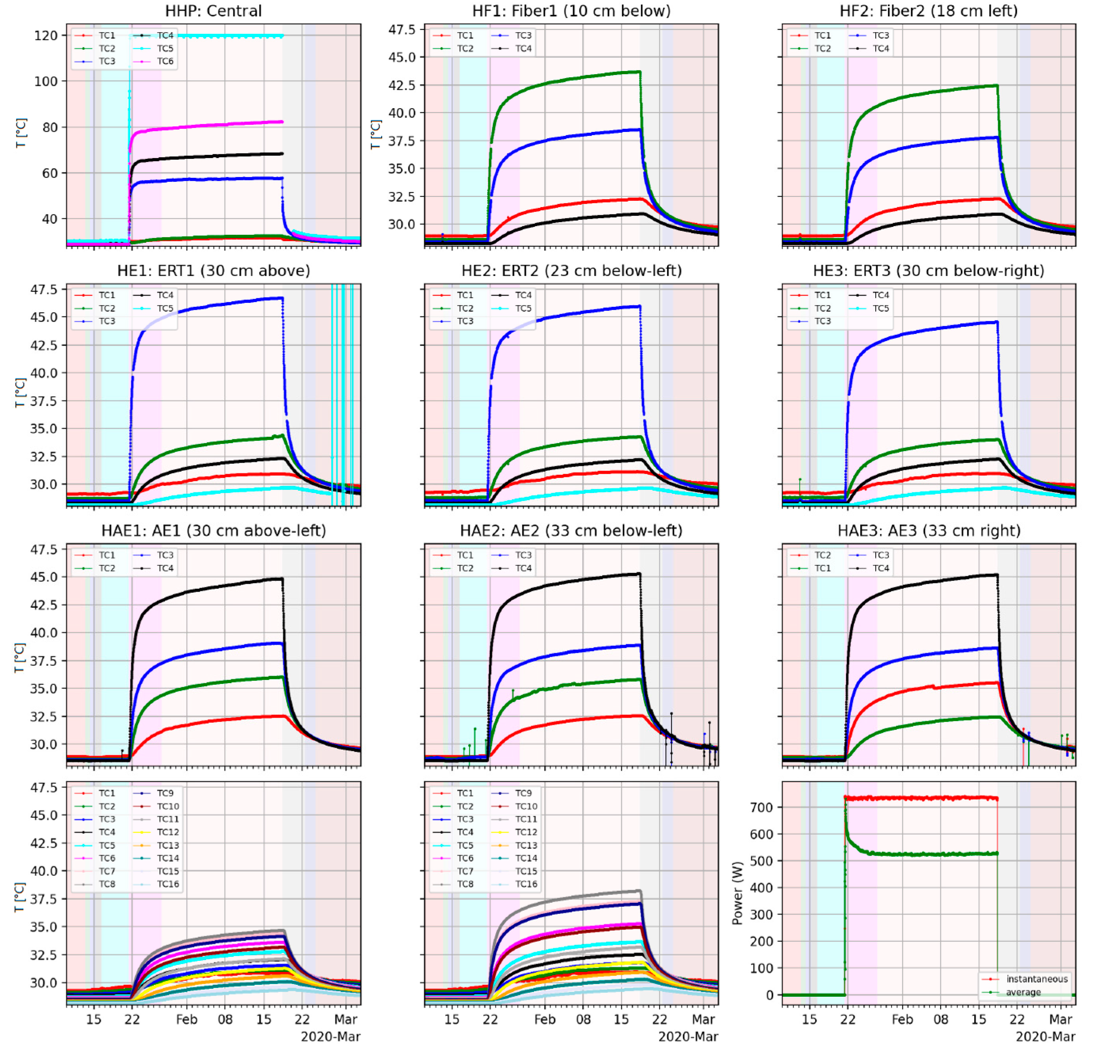
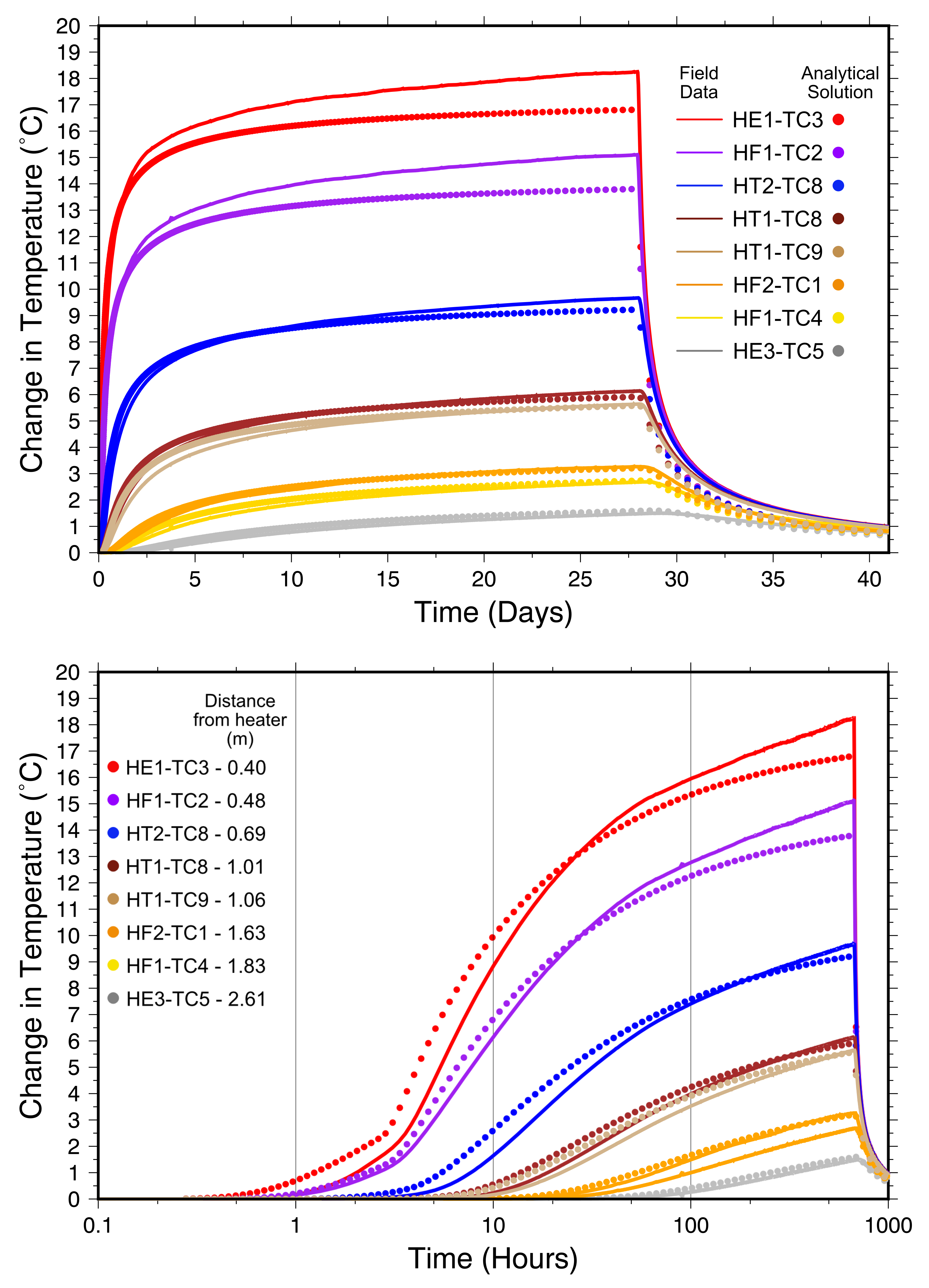
For the MCMC parameter estimation, the analytical solution was fit to the observed change in temperature above background at each location (Figure 4) and the applied power was compared against the measured power applied to the heater (lower right panel of Figure 4). The model–data misfit at each location (sum of squared residuals through time, with data approximately every 15 min) was weighted by at each location and the power data were weighted by 0.2, to improve the fit to all the locations simultaneously (66 thermocouples and power applied to the heated borehole wall). Without these weighting factors, the optimization tends to just fit locations where the solution is numerically largest (e.g., applied power was between 500 and 700 W, while change in temperature ranged from >18 to <1 C at the monitored thermocouples).
2.2. Heat and Brine Flow Model
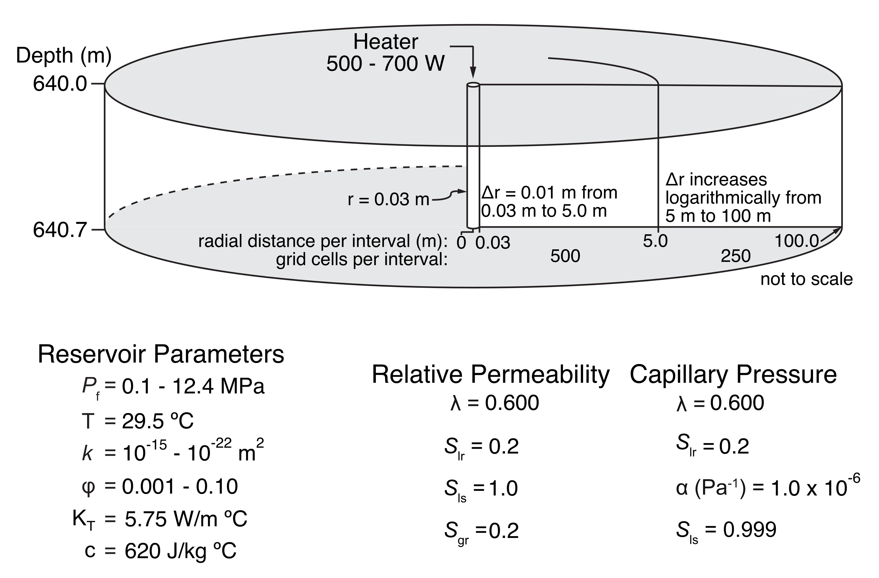
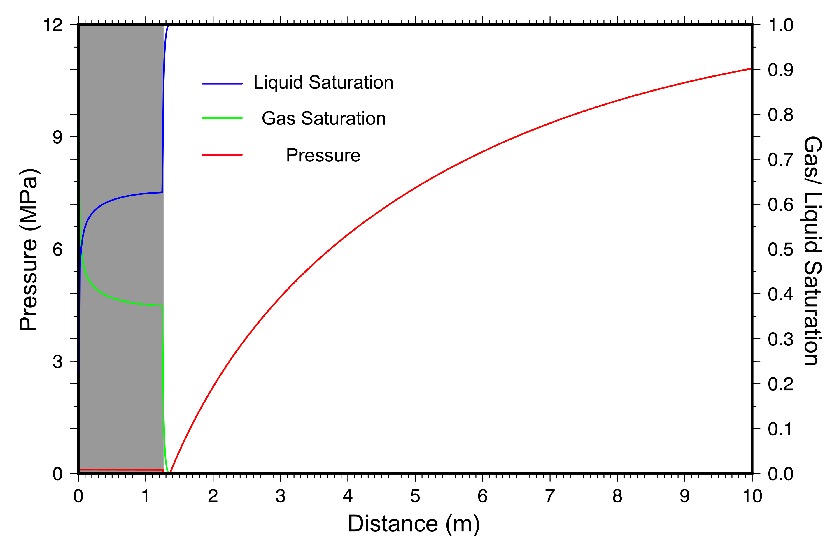
The 1D TH model is conceptualized as a single, cylindrically symmetric layer with 0.7-m thickness and a 100-m lateral extent, the latter of which approximates a semi-infinite radial dimension for the time-scales of interest for this study (Figure 5). The heater is represented by a single grid cell with a radius of 0.03 m and is the inner boundary for the model domain. Beyond the heater, 499 0.01-m grid cells grew up to 5.0 m, then from 5 m to 100 m—the grid cells grow with a constant factor compared to their neighbor. The high resolution of the grid near the heater is chosen to minimize discretization errors where strong gradients and abrupt changes in hydrgeologic parameters are expected to occur [40]. This one-dimensional model treats the heater geometry more realistically than the spherical analytical solution, but it does not represent the presence of the access drift or the unheated portions of the borehole. The DRZ is defined as the 1.25 m after the heater element within the model domain. To model the effects of fracture-matrix flow within the DRZ, the multiple interacting continua (MINC) method is utilized to produce a dual-porosity model representative of fractures induced by drilling/excavation in salt. The MINC method allows for the partitioning of the flow domain into separate computational volumes within each physical element [41]. Since the MINC method is used to represent matrix-to-fracture heat transfer, here the volumes are partitioned into matrix and fracture volumes. We parameterize the MINC formulation by assuming parallel-plate fractures and assigning 98% of the total grid cell volume to the matrix continuum and the remaining 2% to the fracture continuum. This results in the DRZ, being composed of the 124 matrix and the 124 fracture grid cells. Matrix blocks are assumed to have the same properties as intact salt because fractures are characterized by much larger diffusivities than intact salt, which results in early system response being dominated by fractures, whereas late time response is more influenced by the matrix. The MINC method has been implemented in numerous modeling studies focusing on engineered geologic systems, such as CO sequestration [42], enhanced geothermal systems [43], waste water disposal [44], and petroleum reservoirs [45]. Initial conditions involve two different boundary conditions, an atmospheric boundary condition (75% relative humidity, 0.101 MPa, and 29.5 C) at the heater representing connection of the borehole to the drift air and a far-field condition of fully saturated ( = 1), 12 MPa, and 29 C representative of the conditions at 640 m depth at the WIPP [46]. These initial conditions on the borehole and in the far field were held constant during the transient simulation. With these boundary conditions and a 1.25-m region defined as the DRZ, both pressure and gas/liquid saturation are allowed to equilibrate for roughly 5 months, to account for pressure reduction and desaturation that occurred in the time between the drilling of the boreholes at the BATS site and the beginning of testing (Figure 6).
To account for the interfering effects of air and water occupying the same pore space within the DRZ, we use the Van Genuchten [47] constitutive relationships for relative permeability and capillary pressure as a function of saturation. While there are few data available to constrain multiphase properties of salt, we use a model similar to relative permeability models of Blanco-Martín et al. [48] and Rutqvist et al. [49]. Figure 5 presents the complete parameter set for the relative permeability and capillary pressure models used in this study.
The code used in this study is TOUGH2 [39] compiled with the EWASG fluid property module [50]. TOUGH2 solves the TH energy and mass conservation equations for nonisothermal, multiphase flows in geologic porous media. The EWASG module can simulate three-component mixtures of water, sodium chloride, and a non-condensible gas up to 350 C, and salt mass fraction up to halite saturation. The TOUGH2 capability to maintain mass balance of sodium chloride in the solid and liquid phases was not used in our simulations.
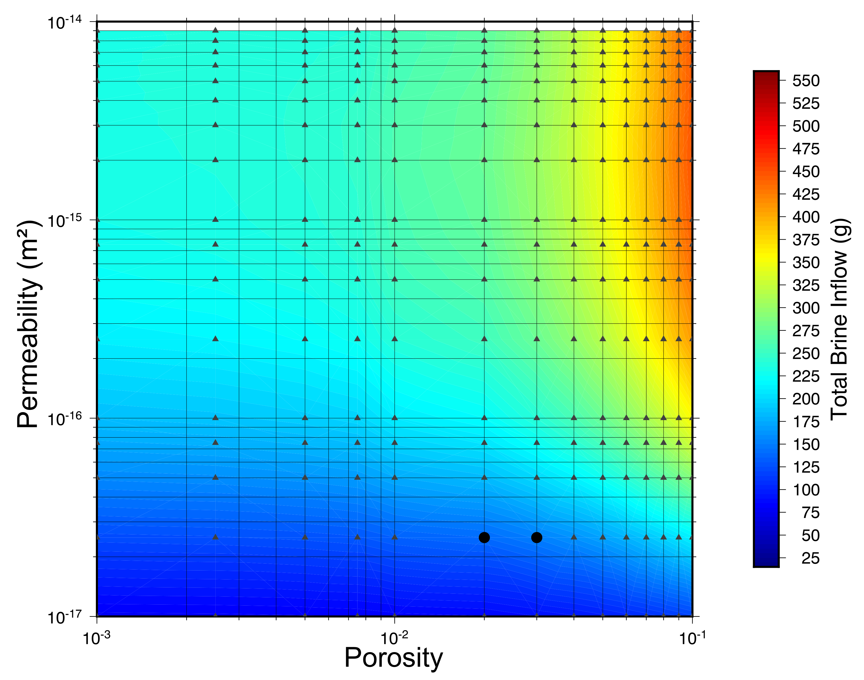
To model the effects of fracture-matrix flow within the DRZ an ensemble of 1D simulations comprising 249 individual simulations with different combinations of permeability and porosity were run to replicate the heating and cooling cycle in the January 2020 BATS experiment. The hydrological parameters for the DRZ range from to m for permeability and from 0.001 to 0.10 for porosity. Since these hydrological parameters are first-order controls on brine flow, the thermal parameters are held constant, at the values estimated from the analytical solution, throughout the ensemble.
3. Results & Discussion
The MCMC parameter estimation using DREAM resulted in the best fit parameters for fitting 66 thermocouples and the applied power. A maximum of 90,000 total iterations were run with three Markov chains, the first 20,000 iterations of each chain were thrown out as part of the burn-in process (last 30,000 iterations were kept to estimate the posterior distribution). The variance in the parameter estimates, as given by the width of the posterior distribution of chains, is small (Figure 7). The fit of the model to the temperature and power data is relatively unique.
Figure 8 illustrates that the analytical solution with the best-fit parameters (i.e., mode of the posterior distributions) underestimates the temperature at thermocouples closer to the heater and matches temperature measured at the thermocouples in the far field. This result however is not surprising, the analytical solution only considers linear heat conduction through homogeneous medium in an infinite spherical domain. In the far field it is much more likely that intact salt is the dominant material type at the BATS site, but closer to the heater there are numerous fractures present due to coalescing DRZs associated with the BATS boreholes (Figure 3). The presence of these air-filled fractures within the salt cause the thermal conductivity within the DRZ to decrease. The thermal conductivity of salt is also known to be a non-linear function of temperature, decreasing at higher temperatures [51,52,53]. Lower thermal conductivity near the heater would result in higher temperatures at the thermocouples closer to the heater. This is further supported by the shape of the temperature curves in Figure 8; the results from the analytical solution produce curves similar in shape and magnitude of those measured in the field. This is crucial because changing thermal conductivity shifts the curves up or down but does not change the overall shape. This suggests that the incorporation of the DRZ is an important component when modeling this system.
The best fit parameters to match temperature at every thermocouple at the BATS site is a thermal conductivity of 5.74 , heat capacity of 620 , and an assumed density of 2160 kg/m ( = ). These parameters are in general agreement with values presented in previous studies for WIPP salt [34,51,52,53]. For example, Bauer and Urquhart [53] conducted laboratory tests on single salt crystals to measure thermal conductivity, the results showed that at room temperature (25 C) pure salt has a thermal conductivity of 6.05 . Kuhlman et al. [34] performed laboratory measurements of bedded salt conductivity in 6 to 7 cm thick and 10 cm in diameter salt cores from the BATS boreholes. The results from Kuhlman et al. [34] showed that the thermal conductivity of salt cores range from 4.5 to 5.0 at 40 C. This range of thermal conductivites from 4.5 to 6.0 is a range that covers thermal conductivity of damaged salt to intact salt crystals, which could be representative of the BATS field site where the thermal conductivity of the DRZ is 4.5 and far-field intact salt should be closer to 6.0 . The thermal conductivity values presented here are closer to the higher end of the range of thermal conductivities measured in the lab, which can give some insight into the proportion of damaged to intact salt around the BATS boreholes. The analytical solution solves for heat conduction through a homogeneous domain, if that domain was completely intact salt we would expect the thermal conductivities to be near 6.0 , whereas if damaged salt (i.e., DRZ) was the dominant media then thermal conductivity should be closer to 4.5 . With the analytical solution resulting in best fit curves for 5.74 . This suggests that there is more intact salt than damaged salt at the BATS field site. While this is a qualitative observation, it supports the decision made to only parse 2% of the volume of grid cells within the DRZ into fractures for the 1D cylindrically symmetric model.
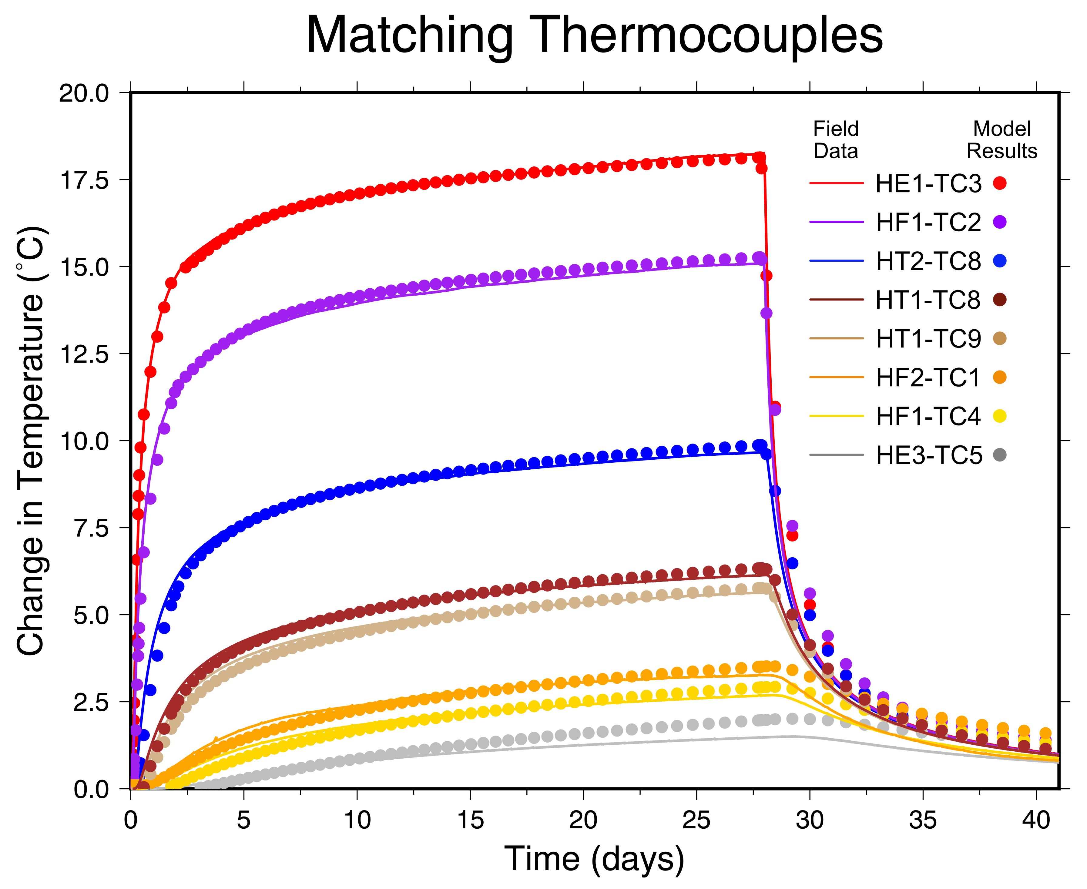
In order to model both heat conduction and brine flow, a single 1D cylindrically symmetric TH TOUGH model is run with the best fit thermal parameters from the analytical solution to compare the measured temperature vs. the modeled temperature at eight representative thermocouples at the BATS site. Figure 9 shows the temperature measured in the field (solid lines) versus the simulated temperature (circles). While the temperature curves are not perfect matches, these results provide confidence that the TOUGH2 model and the discussed conceptualization can accurately reproduce heat conduction at the BATS site within a few tenths of a degree. This verifies the MINC method in this modeling scenario can accurately represent heat flow. Unlike the analytical solution in Figure 8, this model includes non-idealities in the forms of a pressure gradient, brine movement driven by differential thermal expansion of brine and salt, an unsaturated zone near the heater (Figure 6), fully saturated conditions in the farfield, and brine flow within fractures. Even with these complexities present, the thermal parameters provided from the analytical solution still result in a “good” fit for temperature, further supporting that heat conduction is the dominant process for heat flow within salt. The modeled temperature in the TOUGH TH simulation does not under-predict temperature at thermocouples closer to the heater. This is due to using MINC to represent the presence of the DRZ and its associated fractures. Because of how the MINC method works by partitioning the flow domain into different computational volumes, the bulk thermal conductivity of the matrix and fracture volumes present within the DRZ is lower than intact salt due to the low thermal conductivity of the fractures. This overall lower thermal conductivity near the heater allows the TOUGH TH model to predict higher temperatures in the near-field. In addition to fractures lowering the thermal conductivity of the salt, thermal conductivity is known to change as a function of temperature—as temperature increases the thermal conductivity decreases [53]. Both Bauer and Urquhart [53] and Kuhlman et al. [34] measured thermal conductivity of salt at a range of temperatures. Bauer and Urquhart [53] shows that the thermal conductivity of a single salt crystal will range from 6.05 to 3.4 as temperature increases from 25 to 200 C. Similarly, results from Kuhlman et al. [34] show that the thermal conductivity of a salt core ranges from 5.0 to 2.9 as temperature increases from 40 to 200 C. The BATS field test does not reach 200 C, the salt around the heater reaches approximately 100 C and at the nearest thermocouple a max temperature of 47 C, which would result in a slight decrease in thermal conductivity. This temperature dependent thermal conductivity is not accounted for in either the analytical solution or the 1D TOUGH simulations. While temperature dependent thermal conductivity would have an effect on the results presented here, the difference in thermal conductivity of salt at 25 C (6.05 -Bauer and Urquhart [53]) and 50 C (5.5 —Bauer and Urquhart [53]) would only affect a small volume of salt around the heater. For example, the highest temperature measured at a thermocouple is roughly 47 C (Figure 4) and this thermocouple (HE1-TC3) is 0.4 m away from the center of the heater and the furthest thermocouple is 2.98 m away (HT1-TC16). Additionally, the salt surrounding the heater is assumed to be damaged (i.e., part of the DRZ) and the results from Kuhlman et al. [34] show that at 40 C the thermal conductivity of a salt core is 4.9 and 4.8 at 50 C. At higher temperatures, temperature dependent thermal conductivity can have a significant impact on these results, but for the temperature ranges encountered during the January 2020 heater test, this effect is assumed to be of less importance than the distinction between intact and damaged salt.
To further characterize the BATS field site, an ensemble of 1D TOUGH TH simulations is run to investigate brine inflow into the heater borehole. This ensemble consists of 249 combinations of permeability and porosity for the DRZ. Each parameter combination is shown in Figure 10 by dark gray triangles, the ensemble covers permeability ranging from to m and porosity from 0.001 to 0.10. Each simulation is run for 41 days corresponding the heating and cooling phases of the field test. The brine production response of a heated borehole is complex, with exponentially decaying brine production due to pressure changes, and changes in bulk permeability due to thermal expansion, stress changes, and changes in fracture aperture in the salt. We simplify the very complex brine production problem by examining cumulative brine production at the end of a heating and cooling cycle. A brine surface response map of total brine inflow during these 41 days is shown in Figure 10. Varying the hydrological parameters of the DRZ results in the total brine inflow varying from roughly 15 to 565 g. The actual amount of brine inflow measured in the field is 180 g over the course of the experiment, the best parameter combination (two black circles in lower-right of Figure 10) to match this volume of brine inflow are for a permeability of m with a porosity of 0.02 and 0.03. To provide context on how much heat has an effect on the amount of brine and brine inflow, these two best-fit simulations were run again without a heat source. Each simulation resulted in ≈35 g less brine flow into the heater borehole, which illustrates the coupled nature of just the TH response in the salt. The temperature distribution, derived here solely from heat conduction, is responsible for a large portion of the brine production (i.e., thermal expansion of brine as an additional driving force). These permeability values fall within the range of expected permeability from to m reported in Beauheim and Roberts [15]. This range of permeability over seven orders of magnitude exemplifies the possible values present with the DRZ. However, more recently borehole permeability testing was conducted as part of BATS in a heated borehole within the WIPP underground [54]. The results from a series of pressure decay tests resulted in a permeability value between 2.0 to m, which agrees with the results presented here within a very narrow range. These permeability values are also comparable to two well-known studies conducted at WIPP. Stormont [19] utilized gas permeability measurements in salt to quantitively delineate the DRZ from intact salt. Stormont [19] showed that permeability within the DRZ can range from 10 m near the borehole/excavation and decreases to ≈ m up to 2 m away. Pfeifle and Hurtado [55] presents laboratory data from creep and hydrostatic compression tests in order to characterize the evolution and healing of damaged salt. These laboratory tests resulted in permeability values of damaged salt ranging from to m.
Despite to the complex coupled processes that are relevant to salt and the computational resources required to model all relevant processes, we take a simplified approach to analyzing an extremely complex system. This parsimonious modeling approach utilizing analytical and numerical 1D simulations to match field data does not account for all the known coupled processes in salt, it is important to note that these methods reproduce the order of magnitude in measurements made in the field and are therefore representative of effective hydrologic and thermal parameters of bedded salt during a salt heater test. With the analytical solution, we were able to utilize a global nonlinear MCMC optimizer using 90,000 iterations. The results were then transferable into the more complex TH model. It would not have been computationally feasible to perform DREAM MCMC parameter estimation on the TOUGH2 simulations directly. These results offer important insights for future modeling studies by providing constraints on the hydrologic and thermal systems of a geologic salt system and highlights components that are crucial for accurately modeling and matching field data.
4. Conclusions
The safe disposal of radioactive waste in geologic salt has been a topic of research and demonstration since the 1950s. The safety of nuclear waste disposal within bedded salt is contingent on the long-term isolation capabilities of the salt formation as a whole. Understanding short-term heat and brine flow within the DRZ surrounding excavations is an important part of the whole safety assessment for radioactive waste disposal in salt. This study implements a numerical modeling experiment to compare both thermal and hydrological processes during a salt heater test within a bedded salt formation.
The findings from this study are as follows:
- Heat flow in damaged salt around the heater requires reduced thermal conductivity (e.g., heat conduction between intact salt and fractures) to accurately model, while heat flow within undamaged intact salt can be modeled with purely heat conduction.
- Including fractures as part of the DRZ is crucial in matching both the thermal and hydrologic response of salt to heat. The MINC method implemented here illustrates the importance of matrix-fracture heat conduction when matching temperature measured in the field along with fluid flow during a salt heater test.
- The combination of thermal property estimation with a computationally efficient analytical solution and a global optimizer, and 1D TH simulations to estimate hydrologic properties, is a computationally economical approach to constraining effective reservoir properties through matching field data.
In conclusion, results from this study yield insights into heat and fluid flow during a salt heater test, as well as providing an effective way to constrain thermal and hydrological parameters within the highly heterogeneous DRZ. While this study utilizes a simplified approach to modeling an extremely complex system, this study yields important guidance for future modeling studies that aim to incorporate more complex processes.
Author Contributions
Conceptualization, methodology and formal analysis, R.S.J. and K.L.K.; writing—reviewing and editing, R.S.J. and K.L.K. All authors have read and agreed to the published version of the manuscript.
Funding
This research was funded by the US Department of Energy Office of Nuclear Energy (DOE-NE), under the Spent Fuel and Waste Science and Technology (SFWST) program.
Acknowledgments
The authors thank the rest of the team involved in the design, implementation and monitoring of the BATS experiment at Sandia, Los Alamos, and Lawrence Berkeley National Laboratories, through the Test Coordination Office at the Waste Isolation Pilot Plant. This paper describes objective technical results and analysis. Any subjective views or opinions that might be expressed in the paper do not necessarily represent the views of the U.S. Department of Energy or the United States Government. Sandia National Laboratories is a multimission laboratory managed and operated by National Technology & Engineering Solutions of Sandia, LLC, a wholly owned subsidiary of Honeywell International Inc., for the U.S. Department of Energy’s National Nuclear Security Administration under contract DE-NA0003525.
Conflicts of Interest
The authors declare no conflict of interest. The funders had no role in the design of the study; in the collection, analyses, or interpretation of data; in the writing of the manuscript, or in the decision to publish the results.
Abbreviations
The following abbreviations are used in this manuscript:
| 1D | one dimensional |
| 3D | three dimensional |
| BATS | brine availability test in salt |
| DECOVALEX | DEvelopment of COupled models and their VALidation against EXperiments |
| DOE | US Department of Energy |
| DOE-EM | DOE Office of Environmental Management |
| DOE-NE | DOE Office of Nuclear Energy |
| DRZ | disturbed rock zone |
| HLW | high-level waste |
| MCMC | Markov chain Monte Carlo |
| PA | performance assessment |
| SFWST | Spent Fuel and Waste Science and Technology (DOE-NE program) |
| THMC | thermal–hydraulic–mechanical–chemical |
| TSI | WIPP thermal/structural interactions |
| WIPP | Waste Isolation Pilot Plant (DOE-EM facility) |
References
- Hess, H.H.; Adkins, J.; Heroy, W.; Benson, W.; Hubbert, M.; Frye, J.; Russell, R.; Theis, C. The Disposal of Radioactive Waste on Land, Report of the Committee On Waste Disposal of the Division of Earth Sciences; Technical Report 519; National Academy of Sciences-National Research Council Publication: Washington, DC, USA, 1957. [Google Scholar]
- Bradshaw, R.L.; McClain, W.C. Project Salt Vault: A Demonstration of the Disposal of High-activity Solidified Wastes in Underground Salt Mines; Technical Report ORNL-4555; Oak Ridge National Laboratory: Oak Ridge, TN, USA, 1971.
- Llewellyn, G. Thermal responses in underground experiments in a dome salt formation. In Thermal Conductivity 15; Springer: Berlin, Germany, 1978; pp. 277–288. [Google Scholar]
- Just, R. Thermal Analysis Supporting the Design of the Avery Island Field Experiments; Technical Report ORNL/ENG/TM-21; Oak Ridge National Laboratory: Oak Ridge, TN, USA, 1981.
- Van Sambeek, L. Dome-Salt Thermomechanical Experiments at Avery’Island, Louisiana. In The Technology of High-Level Nuclear Waste Disposal; United States Department of Energy: Washington, DC, USA, 1981; p. 100. [Google Scholar]
- Pfeifle, T.W.; Mellegard, K.D.; Senseny, P.E. Constitutive Properties of Salt from Four Sites; Technical Report ONWI-314; RE/SPEC: Rapid City, SD, USA, 1983. [Google Scholar]
- Pfeifle, T.W.; Mellegard, K.D.; Senseny, P.E. Preliminary Constitutive Properties for Salt and Nonsalt Rocks from Four Potential Repository Sites: Technical Report; Technical Report ONWI-450; RE/SPEC: Rapid City, SD, USA, 1983. [Google Scholar]
- Munson, D.E.; Dawson, P. Constitutive Model for the Low Temperature Creep of Salt (with Application to WIPP); Technical Report SAND79-1853; Sandia National Laboratories: Albuquerque, NM, USA, 1979.
- Krause, W. Laboratory-Scale Brine Migration Studies in Southeastern New Mexico Rock Salt; Technical Report RSI-0168; RE/SPEC: Rapid City, SD, USA, 1981. [Google Scholar]
- Stormont, J.C. Plugging and Sealing Program for the Waste Isolation Pilot Plant; Technical Report SAND84-1057; Sandia National Laboratories: Albuquerque, NM, USA, 1984.
- Molecke, M.A.; Sorensen, N.R. Retrieval and analysis of simulated defense HLW package experiments at the WIPP. MRS Online Proc. Libr. Arch. 1988, 127, 683. [Google Scholar] [CrossRef]
- Krumhansl, J.; Stein, C.; Jarrell, G.; Kimball, K. Summary of WIPP Room B Heater Test Brine and Backfill Material Data; Technical Report; Sandia National Laboratories: Albuquerque, NM, USA, 1991.
- Francke, C.T.; Hansen, F.D.; Knowles, M.K.; Patchet, S.J.; Rempe, N.T. Geotechnical Perspectives on the Waste Isolation Pilot Plant (WIPP); Technical Report SAND99-0618C; Sandia National Laboratories: Albuquerque, NM, USA, 1999.
- Hardy, R.D.; Holcomb, D.J. Assessing the Disturbed Rock Zone (DRZ) Around a 655 Meter Vertical Shaft in Salt Using Ultrasonic Waves: An Update; Technical Report SAND2000-0668C; Sandia National Laboratories: Albuquerque, NM, USA, 2000.
- Beauheim, R.L.; Roberts, R.M. Hydrology and hydraulic properties of a bedded evaporite formation. J. Hydrol. 2002, 259, 66–88. [Google Scholar] [CrossRef] [Green Version]
- McTigue, D.F. A Linear Theory for Porous Thermoelastic Materials; Technical Report SAND85-1149; Sandia National Laboratories: Albuquerque, NM, USA, 1985.
- Cosenza, P.; Ghoreychi, M. Coupling between mechanical behavior and transfer phenomena in salt. Ser. Rock Soil Mech. 1996, 20, 285–310. [Google Scholar]
- Borns, D.J.; Stormont, J.C. The delineation of the disturbed rock zone surrounding excavations in salt. In Proceedings of the 30th U.S. Symposium on Rock Mechanics (USRMS), Morgantown, WV, USA, 19–22 June 1989; American Rock Mechanics Association: Alexandria, VA, USA, 1989. [Google Scholar]
- Stormont, J. In situ gas permeability measurements to delineate damage in rock salt. Int. J. Rock Mech. Min. Sci. 1997, 34, 1055–1064. [Google Scholar] [CrossRef]
- Kuhlman, K.L.; Mills, M.M.; Matteo, E.N. Consensus on Intermediate Scale Salt Field Test Design; Technical Report SAND2017-3179R; Sandia National Laboratories: Albuquerque, NM, USA, 2017.
- Su, K.; Ghoreychi, M.; Coste, F.; Pouya, A. Modelling of thermo-hydro-mechanical couplings in fractured media: Application for deep geothermal projects. In Proceedings of the 8th ISRM Congress, Tokyo, Japan, 25–29 September 1995; International Society for Rock Mechanics and Rock Engineering: Tokyo, Japan, 1995. [Google Scholar]
- Serata, S. Reactor Fuel Waste Disposal Project: Development of Design Principle for Disposal Into Underground Salt Cavities. Ph.D. Thesis, University of Texas, Austin, Texas, USA, 1959. [Google Scholar]
- Gloyna, E.F.; Reynolds, T.D. Permeability measurements of rock salt. J. Geophys. Res. 1961, 66, 3913–3921. [Google Scholar] [CrossRef]
- Sherer, N. (Ed.) Salt Repository Project’s Workshop on Brine Migration, University of California-Berkeley, April 17–19, 1985; Number PNL/SRP-SA-14341; Pacific Northwest National Laboratory: Richland, WA, USA, 1987.
- Roedder, E.; Belkin, H. Application of studies of fluid inclusions in Permian Salado salt, New Mexico, to problems of siting the Waste Isolation Pilot Plant. In Scientific Basis for Nuclear Waste Management; Springer: Berlin, Germany, 1979; pp. 313–321. [Google Scholar]
- Roedder, E.; Belkin, H. Thermal gradient migration of fluid inclusions in single crystals of salt from the waste isolation pilot plant site (WIPP). In Scientific Basis for Nuclear Waste Management; Springer: Berlin, Germany, 1980; pp. 453–464. [Google Scholar]
- Shefelbine, H.C. Brine Migration: A Summary Report; Technical Report SAND82-0152; Sandia National Laboratories: Albuquerque, NM, USA, 1982.
- Van Sambeek, L.; Stickney, R.; DeJong, K. Avery Island Heater Tests: Measured Data for 1000 Days of Heating; Technical Report; RE/SPEC: Rapid City, SD, USA, 1983. [Google Scholar]
- Blankenship, D.; Stickney, R. Nitrogen Gas Permeability Tests at Avery Island; Technical Report ONWI-190(3); RE/SPEC: Rapid City, SD, USA, 1983. [Google Scholar]
- Stickney, R.; Van Sambeek, L. Summary of the Avery Island Field Testing Program; Technical Report RSI-0225; RE/SPEC: Rapid City, SD, USA, 1984. [Google Scholar]
- Munson, D.; Hoag, D.; Blankenship, D.; Jones, R.; SJ, W.; Baird, G.; Matalucci, R. Construction of the Thermal/structural Interactions in Situ Tests At the Waste Isolation Pilot Plant (WIPP); Technical Report SAND87-2685; Sandia National Laboratories: Albuquerque, NM, USA, 1997.
- Federal Ministry of Economics and Technology (BMWI). Final Disposal of High-Level Radioactive Waste in Germany—The Gorleben Project; Technical Report; Federal Ministry of Economics and Technology: Berlin, Germany, 2008.
- Guiltinan, E.J.; Kuhlman, K.L.; Rutqvist, J.; Hu, M.; Boukhalfa, H.; Mills, M.; Otto, S.; Weaver, D.J.; Dozier, B.; Stauffer, P.H. Temperature response and brine availability to heated boreholes in bedded salt. Vadose Zone J. 2020, 19, 1–16. [Google Scholar] [CrossRef] [Green Version]
- Kuhlman, K.L.; Mills, M.M.; Jayne, R.S.; Matteo, E.N.; Herrick, C.; Nemer, M.; Heath, J.; Xiong, Y.; Choens, C.; Stauffer, P.; et al. FY20 Update on Brine Availability Test in Salt; Technical Report SAND2020-9034R; Sandia National Laboratories: Albuquerque, NM, USA, 2020.
- Stormont, J.; Howard, C.; Daemen, J.J.K. Changes in Rock Salt Permeability Due to Nearby Excavation; Technical Report SAND91-0269; Sandia National Laboratories: Albuquerque, NM, USA, 1991.
- Rutqvist, J. Status of the TOUGH-FLAC simulator and recent applications related to coupled fluid flow and crustal deformations. Comput. Geosci. 2011, 37, 739–750. [Google Scholar] [CrossRef] [Green Version]
- Carslaw, H.S.; Jaeger, J.C. Conduction of Heat in Solids; Oxford University Press; Amen House: London, UK, 1959. [Google Scholar]
- Vrugt, J.A. Markov chain Monte Carlo simulation using the DREAM software package: Theory, concepts, and MATLAB implementation. Environ. Model. Softw. 2016, 75, 273–316. [Google Scholar] [CrossRef] [Green Version]
- Pruess, K.; Oldenburg, C.M.; Moridis, G. TOUGH2 User’s Guide Version 2; Technical Report LBNL-43134; Lawrence Berkeley National Laboratory: Berkeley, CA, USA, 1999.
- Liu, H.; Doughty, C.; Bodvarsson, G. An active fracture model for unsaturated flow and transport in fractured rocks. Water Resour. Res. 1998, 34, 2633–2646. [Google Scholar] [CrossRef]
- Pruess, K.; Narasimhan, T. A Practical Method for Modeling Fluid and Heat Flow in Fractured Porous Media; Technical Report LBL-13487; Lawrence Berkeley Laboratory: Berkeley, CA, USA, 1982.
- Jayne, R.S.; Wu, H.; Pollyea, R.M. Geologic CO2 sequestration and permeability uncertainty in a highly heterogeneous reservoir. Int. J. Greenh. Gas Control. 2019, 83, 128–139. [Google Scholar] [CrossRef]
- Pruess, K. Enhanced geothermal systems (EGS) using CO2 as working fluid—A novel approach for generating renewable energy with simultaneous sequestration of carbon. Geothermics 2006, 35, 351–367. [Google Scholar] [CrossRef] [Green Version]
- Pollyea, R.M.; Chapman, M.C.; Jayne, R.S.; Wu, H. High density oilfield wastewater disposal causes deeper, stronger, and more persistent earthquakes. Nat. Commun. 2019, 10, 1–10. [Google Scholar] [CrossRef] [PubMed]
- Sepehrnoori, K.; Xu, Y.; Yu, W. Numerical approaches for modeling complex fractures. In Developments in Petroleum Science; Elsevier: Amsterdam, The Netherlands, 2020; Volume 68, pp. 31–42. [Google Scholar]
- Mills, M.M.; Kuhlman, K.L.; Matteo, E.N.; Herrick, C.G.; Nemer, M.; Heath, J.E.; Xiong, Y.; Paul, M.J.; Stauffer, P.; Boukhalfa, H.; et al. Salt Heater Test (FY19); Technical Report SAND2019-10240R; Sandia National Laboratories: Albuquerque, NM, USA, 2019.
- Van Genuchten, M.T. A closed-form equation for predicting the hydraulic conductivity of unsaturated soils. Soil Sci. Soc. Am. J. 1980, 44, 892–898. [Google Scholar] [CrossRef] [Green Version]
- Blanco-Martín, L.; Rutqvist, J.; Battistelli, A.; Birkholzer, J.T. Coupled processes modeling in rock salt and crushed salt including halite solubility constraints: Application to disposal of heat-generating nuclear waste. Transp. Porous Media 2018, 124, 159–182. [Google Scholar] [CrossRef] [Green Version]
- Rutqvist, J.; Hu, M.; Wu, Y.; Blanco-Martin, L.; Birkholzer, J. Salt Coupled THMC Processes Research Activities at LBNL: FY2018 Progress; Technical Report LBNL-2001170; Lawrence Berkeley National Laboratory: Berkeley, CA, USA, 2018.
- Battistelli, A.; Calore, C.; Pruess, K. The simulator TOUGH2/EWASG for modelling geothermal reservoirs with brines and non-condensible gas. Geothermics 1997, 26, 437–464. [Google Scholar] [CrossRef]
- Acton, R. Thermal conductivity of SE New Mexico rocksalt and anhydrite. In Thermal Conductivity 15; Springer: Berlin, Germany, 1978; pp. 263–276. [Google Scholar]
- Sweet, J.; McCreight, J. Thermal Properties Measurements on Rocksalt Samples From the Site Of the Proposed Waste Isolation Pilot Plant; Technical Report SAND80-0709; Sandia National Laboratories: Albuquerque, NM, USA, 1980.
- Bauer, S.J.; Urquhart, A. Thermophysical Properties of Reconsolidating Crushed Salt; Technical Report SAND2014–2240; Sandia National Laboratories: Albuquerque, NM, USA, 2014.
- Guiltinan, E.; Boukhalfa, H.; Dangelmayr, M.; Dozier, B.; Janicke, M.; Marina, O.; Otta, S.; Rahn, T.; Ware, D.; Weaver, D.; et al. 2020 LANL Contributions to the BATS test in WIPP; Technical Report LA-UR-20-266603; Los Alamos National Laboratory: Los Alamos, NM, USA, 2020.
- Pfeifle, T.; Hurtado, L. Permeability of Natural Rock Salt from the Waste Isolation Pilot Plant (WIPP) During Damage Evolution and Healing; Technical Report SAND98-0417C; Sandia National Laboratories: Albuquerque, NM, USA, 1998.
Figure 1.
Thermal–Hydrological-Mechanical–Chemical (THMC) coupled processes in salt [21].
Figure 1.
Thermal–Hydrological-Mechanical–Chemical (THMC) coupled processes in salt [21].

Figure 2.
Brine types and flow mechanisms in salt (modified from Shefelbine [27]).
Figure 2.
Brine types and flow mechanisms in salt (modified from Shefelbine [27]).

Figure 3.
Borehole configuration for each array in the BATS field test (from Kuhlman et al. [34]).
Figure 3.
Borehole configuration for each array in the BATS field test (from Kuhlman et al. [34]).

Figure 4.
Thermocouple temperature and heater power through time during the BATS heater test (from Kuhlman et al. [34]).
Figure 4.
Thermocouple temperature and heater power through time during the BATS heater test (from Kuhlman et al. [34]).

Figure 5.
Schematic illustration and model properties for the 1D cylindrical model domain used for this study. The permeability and porosity values shown cover the ranges for both fracture (10–10 m and 0.001 to 0.10 for ensemble simulation) and intact salt (10 m and 0.001, respectively). The heater grid cell radius is 0.03 m. The next 500 0.01-m grid cells reach 5.03 m, another 250 grid cells increase with a constant factor compared to their neighbor and are added to represent semi-infinite later dimensions of 100 m. The DRZ is defined as an area extending 1.25 m from the heater. The DRZ is composed of 124 matrix and 124 fracture grid cells as described by the MINC method.

Figure 6.
Pressure and liquid/gas saturation initial conditions for each 1D simulation. The shaded grey region represents the extent of the DRZ and the double-porosity portion of the mesh, which extends 1.25 m from the heater.
Figure 6.
Pressure and liquid/gas saturation initial conditions for each 1D simulation. The shaded grey region represents the extent of the DRZ and the double-porosity portion of the mesh, which extends 1.25 m from the heater.

Figure 7.
Posterior density estimates for each parameter using DREAM. Applied borehole wall temperature is + 29.5 C (background). Red curves are best-fit Gaussian, illustrating mean and variance of entire chain;mode (tallest bar in histogram) was used as measure of best estimate.
Figure 7.
Posterior density estimates for each parameter using DREAM. Applied borehole wall temperature is + 29.5 C (background). Red curves are best-fit Gaussian, illustrating mean and variance of entire chain;mode (tallest bar in histogram) was used as measure of best estimate.

Figure 8.
Analytical solution for best fit parameters at 8 thermocouples. The top panel shows the predicted temperature at each thermocouple in linear time and the bottom panel shows the temperature fits in log-time. The field data are denoted by solid lines and the modeled temperature are the corresponding colored circles.

Figure 9.
Numerical modeling results for change in temperature at three thermocouples in-plane with the heater over time. The solid lines represent the temperature measured in the field and the dots represent the modeled temperature at each location.
Figure 9.
Numerical modeling results for change in temperature at three thermocouples in-plane with the heater over time. The solid lines represent the temperature measured in the field and the dots represent the modeled temperature at each location.

Figure 10.
Cumulative brine inflow into the heater borehole during both heating and cooling phases of experiment. Black triangles show parameter combination for individual simulations (N = 294). Black dots represent hydraulic parameters that have total brine inflow within ±10 g of brine inflow measured in the field.

Publisher’s Note: MDPI stays neutral with regard to jurisdictional claims in published maps and institutional affiliations. |
© 2020 by the authors. Licensee MDPI, Basel, Switzerland. This article is an open access article distributed under the terms and conditions of the Creative Commons Attribution (CC BY) license (http://creativecommons.org/licenses/by/4.0/).
Share and Cite
MDPI and ACS Style
Jayne, R.S.; Kuhlman, K.L. Utilizing Temperature and Brine Inflow Measurements to Constrain Reservoir Parameters During a Salt Heater Test. Minerals 2020, 10, 1025. https://0-doi-org.brum.beds.ac.uk/10.3390/min10111025
AMA Style
Jayne RS, Kuhlman KL. Utilizing Temperature and Brine Inflow Measurements to Constrain Reservoir Parameters During a Salt Heater Test. Minerals. 2020; 10(11):1025. https://0-doi-org.brum.beds.ac.uk/10.3390/min10111025
Chicago/Turabian StyleJayne, Richard S., and Kristopher L. Kuhlman. 2020. "Utilizing Temperature and Brine Inflow Measurements to Constrain Reservoir Parameters During a Salt Heater Test" Minerals 10, no. 11: 1025. https://0-doi-org.brum.beds.ac.uk/10.3390/min10111025
Note that from the first issue of 2016, this journal uses article numbers instead of page numbers. See further details here.