
Investigation of Backfilling Step Effects on Stope Stability


School of Mining and Petroleum Engineering, University of Alberta, Edmonton, AB T6G1H9, Canada
*
Author to whom correspondence should be addressed.
Mining 2021, 1(2), 155-166; https://0-doi-org.brum.beds.ac.uk/10.3390/mining1020010
Submission received: 29 May 2021
/
Revised: 9 July 2021
/
Accepted: 23 July 2021
/
Published: 29 July 2021
(This article belongs to the Special Issue Recent Advances in Underground Mine Planning, Scheduling, and Optimization: Theory and Applications)
Abstract
:Cemented rock fill (CRF) is commonly used in cut-and-fill stoping operations in underground mining. This allows for the maximum recovery of ore. Backfilling can improve stope stability in underground workings and then improve ground stability of the whole mine site. However, backfilling step scenarios vary from site to site. This paper presents the investigation of five different backfilling step scenarios and their impacts on the stability of stopes at four different mining levels. A comprehensive comparison of displacements, major principal stress, and Stress Concentration Factor (SCF) was conducted. The results show that different backfilling step scenarios have little influence on the final displacement for displacement in the stopes. Among the five backfilling scenarios, the major principal stress and stress concentration factor (SCF) have almost the same final results. The backfilling scenario SCN-1 is the optimum option among these five backfilling scenarios. It can immediately prevent the increase of the displacement and reduce the sidewall stress concentration, thereby preventing possible failures. Using the same strength of CRF can achieve the same effects among the four mining levels. Applying backfilling CRF of the same strength at different mining depths is acceptable and feasible to improve the stability of the stopes.
1. Introduction
Using backfilling for mined-out stopes has been widely used in underground mines over the past several decades. In many underground mines, cemented rockfill (CRF) as backfill material is common [1,2]. Cemented rock fill (CRF) allows for the full recovery of an orebody while achieving global mine site stability [3,4,5,6]. In order to achieve these goals, the exposed CRF masses require adequate compressive strength and stiffness to resist the stresses and limit the displacement associated with displacements in the rock mass surrounding the excavations. Moreover, the cemented rockfill (CRF) is a type of backfill with simple operation, moderate capital cost while acquiring good strength. Backfilling with controlled and rational specifications can improve ground support and pillar recovery effectively in underground mining [7,8,9].
To date, lots of work has been done to analyze the cemented rockfill (CRF) property with different component ratios in the laboratory and backfilling effects of the stope stability under static and dynamic conditions and the relation between the backfilled CRF and the stope spans [10]. Lingga [11,12,13] conducted detailed laboratory experiments, including compressive strength and stiffness and the shear properties, to achieve better ratios among the cement, water, and aggregate to get proper backfilled CRF. Saw [10] and Stone [14] studied the different mixtures of water, waste rock, binder, and their influences on CRF properties at different curing times, temperatures, and humidity to achieve a target strength at different mining stages.
Helinski [15,16], Fahey [17], and Gibson [18] studied the curing process and the arching phenomenon of the backfilled CRF in the stopes by comparing field measured data and the back analysis based on laboratory measurements. In the blasthole stoping method, the backfilled CRF is prepared for the secondary stope blasting. Emad [19,20,21] and Henning [22] examined and simulated different blast loads and profiles to assess the effects of blast vibrations on CRF backfilled stopes by monitoring vibration in a CRF stope. Thompson [23,24,25] quantified the evolution of total geo-pressures and pore pressures within the core of the backfilled CRF to assess the stability by conducting in situ experiments in long-hole stopes. Kumar [26] conducted laboratory studies to characterize various mechanical properties of cemented rockfill (CRF) formulations and developed the relationship between the strength and the unit weight of CRF to better design and control CRF quality during its large-scale application in underground cut-and-fill blasthole stopes. Cordova [5] studied the effect of particle size distribution upon the overall uniaxial compressive strength (UCS) of the cemented rockfill (CRF). Seymour [27,28] and Tesarik [29,30] studied the long-term relationship between the compressive and tensile strength of CRF and the stability of CRF undercut spans by reading the monitoring data of the installed instruments in the test sites. Marlow [31] compared the shotcrete ribs and the cemented rock fill (CRF) to weaken the hazards and control convergence and overbreak during the backfilling process. Sainsbury [32,33] developed a novel numerical modeling approach to simulate the particulate nature of CRF accurately. It determined the stability of CRF exposures by conducting novel numerical models that incorporate extraction, filling, and the exposure sequence of the CRF-filled stopes. Some other works [34,35,36] have achieved significant and valuable outcomes about the cemented rockfill (CRF) property and mining and backfilling sequence effects on stope stability and global mine stability.
However, due to practical difficulties, it is impossible to conduct different backfilling scenario tests to study the influence of different backfilling scenarios on the stope stability in the in situ field. With rapid developments in computer software and hardware, employing numerical modeling methods to conduct various physical phenomena simulations in rock mechanics and rock engineering has achieved significant progress. Using numerical modeling to model elastoplastic, non-linear, and post-yield behavior of rock masses and the effects of in situ stresses and excavation features on the mining works can help researchers understand the “real world” in underground mining [37]. Thus, the application of the numerical simulation will be an excellent choice to investigate the influence of different backfilling scenarios on stope stability. This paper presents the investigations of five different backfilling scenarios in a hard rock mine by applying the numerical simulation of a full-size 3D mine model to analyze the effects of the backfilled CRF on the sidewall displacement, principal stresses, and the stress concentration factor (SCF), and then decide the best backfilling scenario.
2. Methodology
2.1. Background
Backfilling with controlled specifications can be employed for improved ground support and pillar recovery in underground metalliferous mine workings [2]. The backfill is required to fill the extracted voids and provide regional support [15]. Cemented rockfill has proven to be of critical importance to the operation of several Canadian mines [32,33]. Cemented rockfill (CRF) is commonly used in conjunction with the underhand cut-and-fill mining method to provide ground support in weak rock mass conditions, particularly in underground mines. The CRF supports the mine roof’s overlying material and confines the rock pillars and room abutments [3,5,38,39]. In the case study mine in this research, several reported failures of the access drifts on the backfilling levels [40].
Underground mining involves creating voids that, in many mining operations, subsequently require backfilling to stabilize underground excavations and optimize ore recovery. Backfilling is a form of passive support and is used to prevent ore dilution from filing hanging walls and footwalls, and it also enables reasonable ground control [36,41]. Backfill is used to fill the stope and serves basically as the working floor for the next slice and provides some degrees of confinement to the stope walls.
2.2. Numerical Model Configuration
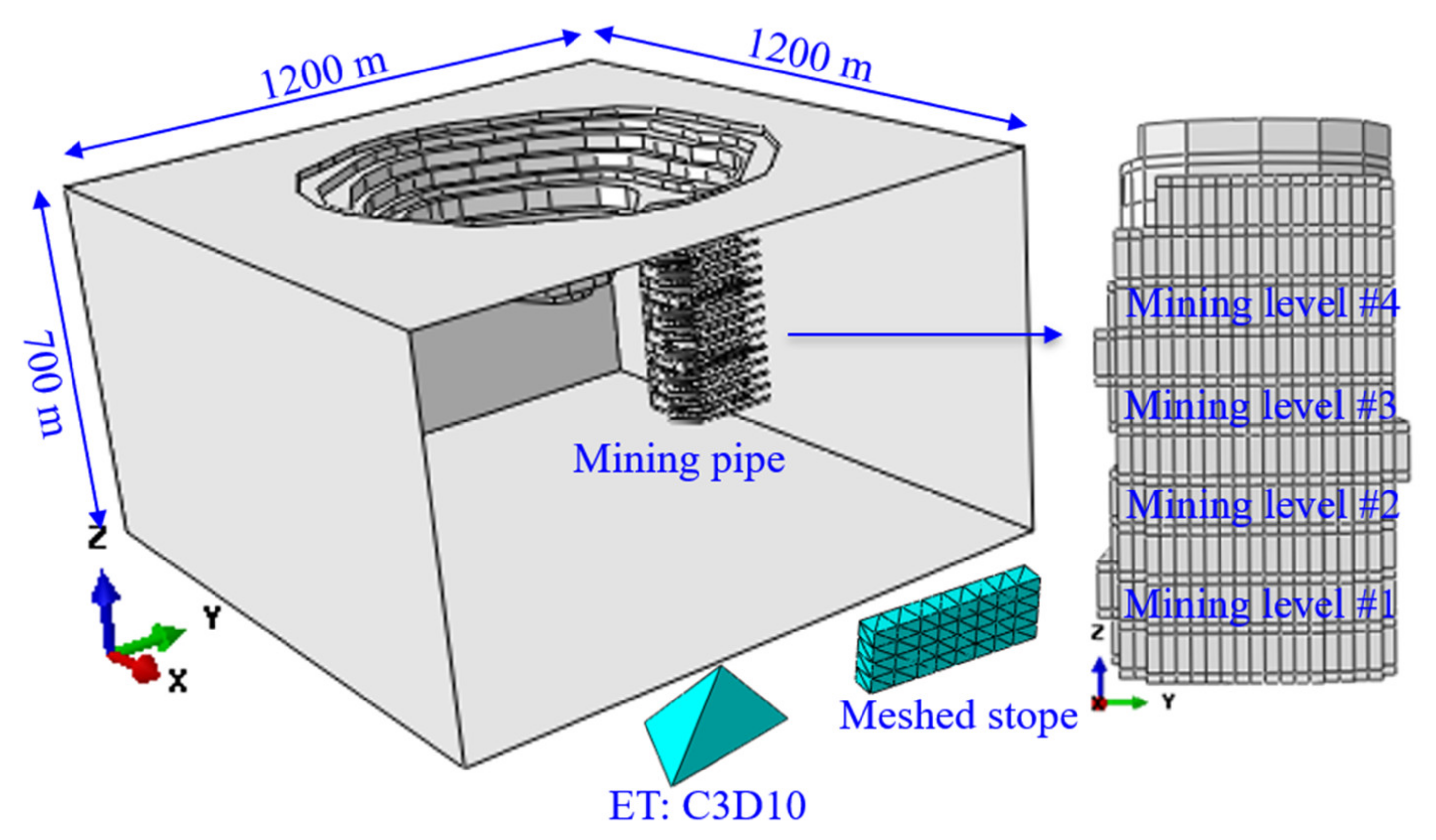
To better study the effect of different backfilling scenarios on the stope stability, one hard rock underground mine was chosen as a case study. The mine in this study was initially operated as an open-pit mine. Once the open-pit mining was completed, the mining operation shifted to the underground. The orebody extends in the mining pipe under the open pit. It has been proved that full-size 3D models can estimate the deformations of underground openings and explore the mining-induced stress redistribution paths during excavation than 2D models [42,43,44]. Thus, a full-size 3D elastoplastic finite element numerical model was established using the codes of ABAQUS [42,43,44,45,46]. The analysis domain has a size of 1200 m × 1200 m × 700 m (length × width × depth). A study of mesh density convergence was conducted [42], and the total number of elements of the model was determined. At the bottom of the model, the boundary conditions are applied to fix the bottom, and the top surface is set free. The horizontal restraints on both X and Y directions are applied on the four vertical boundaries of the model. There are ten mining levels, and four mining levels are chosen for this study. The elevation difference among the four marked mining levels is 30 m. The mining depths of these four different mining levels are 300, 270, 240, and 210 m, from mining level #1 to mining level #4, respectively. Due to the unregular geometry shape of some structures in the mining pipe, to better represent the real geometry of the mining pipe and to achieve better results of the redistributed stress field, in this full-size mine-scale model, the ten-node quadratic tetrahedron mesh element type (ET:C3D10) [42,46] was used to conduct the simulation study, as shown in Figure 1.
2.3. Mechanics Properties of Rock Mass
Table 1 presents the material properties applied in the simulation model [11,42]. In this mine, the host rock is granite. We conducted laboratory tests to achieve the rock mechanics property parameters of the materials at the University of Alberta. MP#1 is the No.1 mining pipe in this hard rock mine. The behavior of the rock mass was assumed to be governed by an elastoplastic constitutive relation [11,13,42], which is based on the Mohr–Coulomb criterion. The Mohr–Coulomb failure criterion has linear equations in principal stress space describing the stress state for anisotropic material failure [46,47]. ABAQUS [46] employs the Mohr–Coulomb failure criterion. Here, E is the elastic Young’s modulus, C is the cohesive strength, ϕ is the angle of friction, γ is the unit weight, ν is the Poisson’s ratio, and σc is the maximum uniaxial compressive strength [11,42]. By conducting the shear strength test [11], the residual friction angle (ϕr) is 41°, and the residual cohesion strength (Cr) is 0.78 MPa.
2.4. Backfilling Step Scenarios
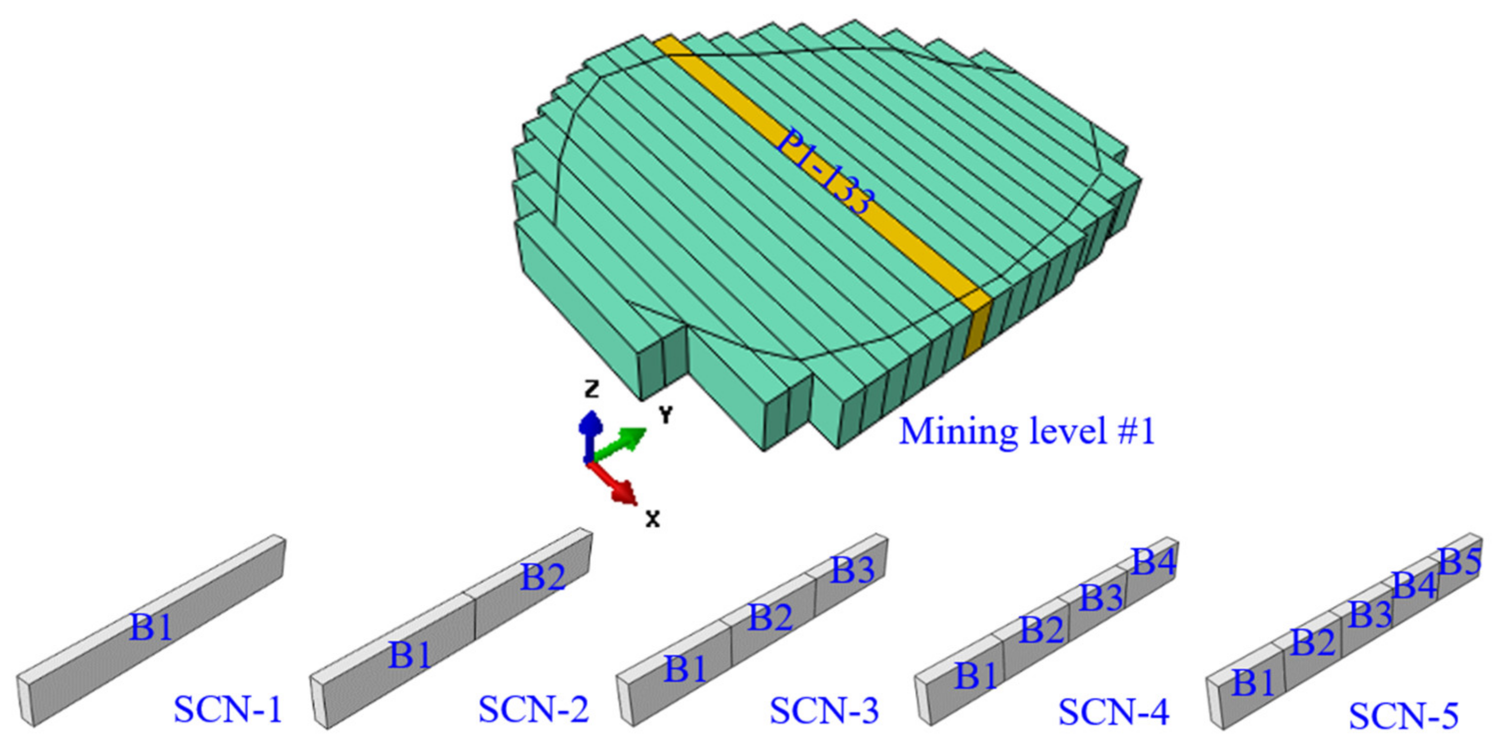
The four chosen mining levels have the same number of stopes in each mining level, and it is 21 stopes. One stope P1–133 in the middle of the mining level was chosen as the case study stope in this study. This stope had a size of 8 m × 20 m × 150 m (width × height × length). Five different backfilling step scenarios were conducted to complete this simulation. The model with the mining pipe MP#1 was calibrated and validated by comparing the displacements recorded at the case study mine with the displacements predicted by this model [42].
The five different backfilling scenarios are shown in Figure 2. For scenario SCN-1, it has one backfilling part, backfilling-1 (B-1), and the length is 150 m. SCN-2 has two equal backfilling parts, B-1 and B-2, and each part is 75 m long. There are three backfilling parts for the SCN-3 scenario: B-1, B-2, and B-3, and each part is 50 m long. SCN-4 has four equal parts, and SCN-5 has five equal parts. Each part of SCN-4 and SCN-5 are 37.5 and 30 m long, respectively.
As shown in Table 2, for backfilling scenario SCN-1, after the completion of the excavation of the stope, the stope will be backfilled in one time to backfill the whole void of the stope. Backfilling scenario SCN-2 takes two steps to finish the backfilling, the first step is B-1, and the second step is B-2. For backfilling scenario SCN-3, once the stope is mined out, it takes three steps to backfill the stope void with three equal backfilling parts, B-1, B-2, and B-3. Backfilling scenario SCN-4 and SCN-5 will take four and five steps to complete the backfilling, from B-1 to B-4 and B-5, respectively. In this paper, an assumption is made that once the CRF is backfilled, it takes into effect immediately, and the curing time is ignored.
In all five scenarios, the first simulation step, Step1 (S1), is the geostatic step to calculate the initial state of stress before excavation, and the second simulation step, Step2 (S2), is to excavate the whole stope. For scenario SCN-1, the third simulation step, Step3 (S3), is to backfill the entire stope. In scenario SCN-2, it takes steps S3 and S4 to complete the backfilling of the stope. Following this logic, the scenarios SCN-3 and SCN-4 take 5 and 6 steps in total, respectively, to complete the backfilling. For scenario SCN-5, it takes five steps, S3, S4, S5, S6, S7, to finish the backfilling.
3. Results
Failure of underground openings in hard rocks is a function of the in situ stress magnitudes, the characteristics of the rock mass, the intact rock strength, and the fracture network [36,42,44]. In most scenarios, the failures were caused by over-displacement in the roof, swellings in the sidewalls, and over-heave in the floor. In this paper, the middle points of the two sidewalls of the stope were chosen as reference points to monitor the stope convergence.
3.1. Backfilling Step Effect on Sidewall Displacement
Compared to the roof displacement and floor heave, the swellings of the sidewalls were more evident in this hard rock mine. As soon as the stope is excavated, the intact stress field changes, which causes stress release on the sidewalls due to displacement in the sidewall. The flowing figures show the sidewall displacement of the four mining levels.
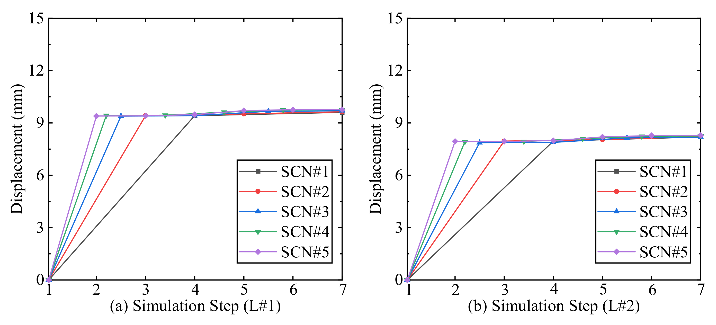
The changes of sidewall displacement of mining level #1 and level #2 are shown in Figure 3, and the changing trend of both levels #1 and #2 are similar. After Step2 of excavation of the whole stope, the displacement increases dramatically to the maximum values. With the process of backfilling, the displacement shows almost no more increase. The sidewall displacement in mining level #1 is about 10 mm, and the displacement of mining level #2 is about 8 mm, after the excavation of the stope. Thus, in each mining level, the final displacements are almost the same, even with different backfilling scenarios.
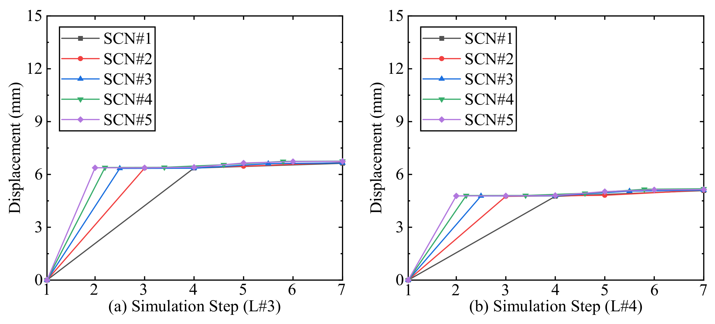
Similar to the changing trend in mining level #1 and level #2, the sidewall displacement achieves the maximum value after excavating the whole stope, as shown in the following Figure 4. With a displacement of about 7 mm in mining level #3 and a displacement of about 5 mm in mining level #4, there is no increase in the sidewall displacement after the step of backfilling. The final displacements of each mining level are the same under different backfilling scenarios.
Comparing the displacement of the four mining levels, as shown in Figure 3 and Figure 4, with the increase of the mining depth, the displacement of the sidewall shows an increasing trend after the completion of the excavation. The deeper the mining level goes, the larger the displacement increases. After the backfilled CRF takes into effect, there is no more increase of sidewall displacement at these four different mining levels.
3.2. Backfilling Step Effect on Major Principal Stress
Excavation in underground mining will disturb the entire stress field around the mined stope. The mining-induced stress redistribution may result in failure of the roof, sidewall, and floor in the stope. Knowing the change path of the redistributed principal stress provides a reference base for the mining schedule and corresponding support strategies.
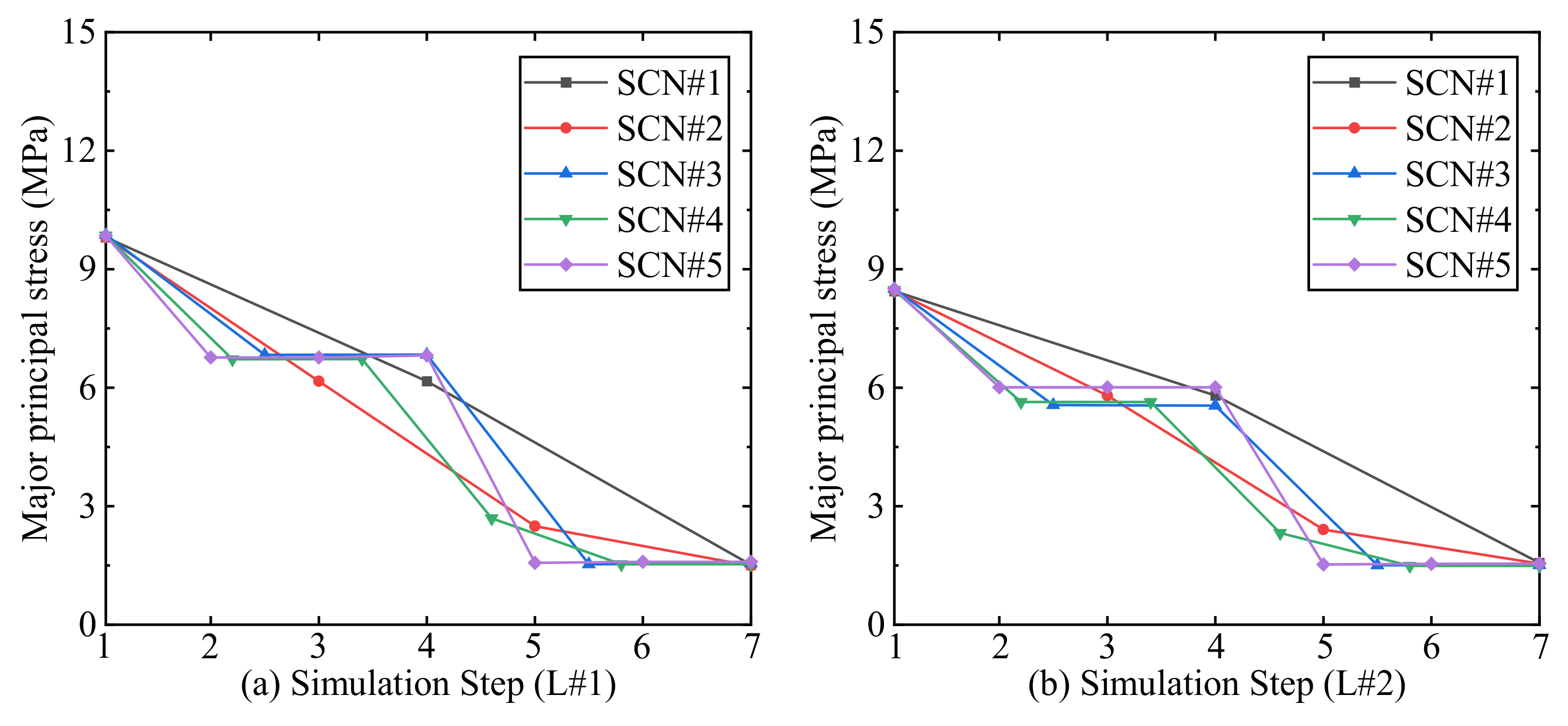
The major principal stress change trends with the influence of the backfilling of level #1 and level #2 are shown in Figure 5. For both mining levels, the excavation will trigger the release of the principal stress at the middle of the sidewalls. The principal stress decreases gradually from Step1 to Step7, and at the last step, the principal stress will achieve a stable level. At each mining level, all the five different backfilling scenarios have almost the same final principal stress. For example, level #1 sees a decrease of 83% of the major principal stress from the before-excavation to the after-backfilling. The decreasing percent of major principal stress at level #2 is about 82%, and it is almost the same as that of level #1.
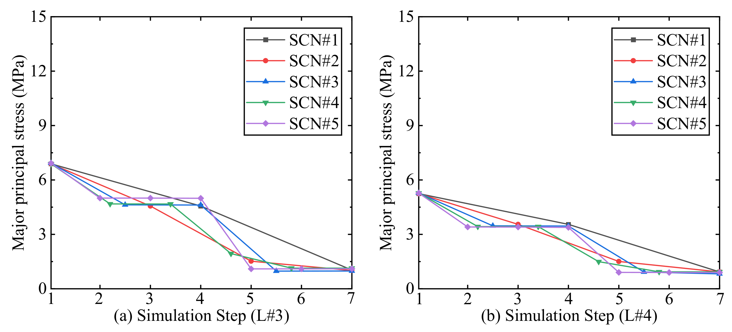
The major principal stress of the stope in level #3 and level #4 presents a similar trend with level #1 and level #2, as shown in Figure 5 and Figure 6. Due to the shallower mining depth, the initial principal stress at Step1 is minor compared with the previous two mining levels and the final principal stress status. In addition, the principal stress change amplitude of each backfilling scenario is smaller. The final principal stress status of level #3 is over 1 MPa, while the final status of level #4 is under 1 MPa. Similar to level #1 and level #2, the decreasing percentage of major principal stress of level #3 is about 82%, from before-excavation 6.8 MPa to after-backfilling 1.2 MPa, and that of level #4 is about 81%, from 5.2 MPa to 0.98 MPa.
With the mining levels close to the top surface of the mining pipe, the starting principal stress level at Step1 decreases, and the final principal stress at the last Step7 sees a slight difference among the four mining levels. When the backfilling starts to affect all four mining levels, the backfilling body will share the mining-induced redistributed stress. SCN-5 gives an evident change trend to this. When the backfilling body takes into effect, the principal stress sees a plunge from Step4 to Step5, and after that, the principal stress achieves a stable status. The decreasing percentages of the major principal stress from before-excavation to after-backfilling of these four mining levels are very close to each other, with a value over 80%.
3.3. Backfilling Step Effect on Stress Concentration Factor (SCF)
Wiseman found that the stability of tunnels in massive rocks can be assessed by comparing stresses on the boundary of essentially square openings to the laboratory uniaxial compressive strength. In 1979, he proposed the stress concentration factor (SCF) to assess the stability of the sidewalls according to laboratory experiments and in situ observations and measurements in South African mine tunnels [48].
where σ1 and σ3 are the in situ excavation-induced major and minor principal stress, respectively, σc is the laboratory uniaxial compressive strength (UCS).
SCF = (3σ1 − σ3)/σc
As a critical factor, the stress concentration factor (SCF) is widely used to assess tunnel sidewall stability. In addition, with the influence of the backfilling, the sidewall stress concentration factor (SCF) can also be used to assess the sidewalls in the stopes.
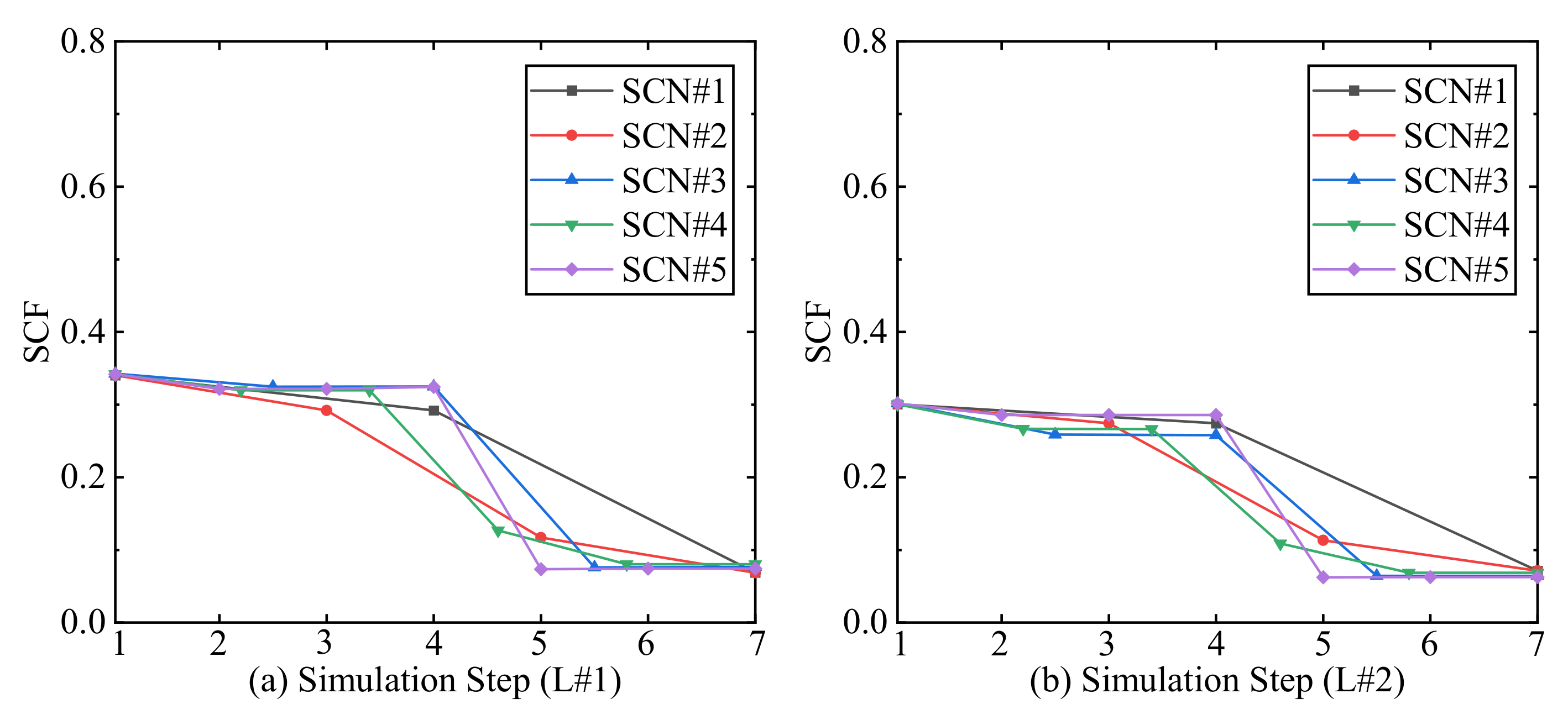
At the starting geostatic Step1, the sidewall stress concentration factor has the maximum value in level #1 and level #2, as shown in Figure 7. After the excavation Step2, the stress concentration presents a stable status without noticeable changes among SCN-3, SCN-4, and SCN-5, while for the scenarios of SCN-1 and SCN-2, the changes are more extensive. After the backfilling body takes effect, the stress concentration factor witnesses a sharp decrease and achieves a stable value of about 0.05 in level #1 and level #2 among the five different backfilling scenarios. The sidewall stress concentration factor (SCF) sees a 76% decrease in level #1, and level #2 sees a 77% decrease.
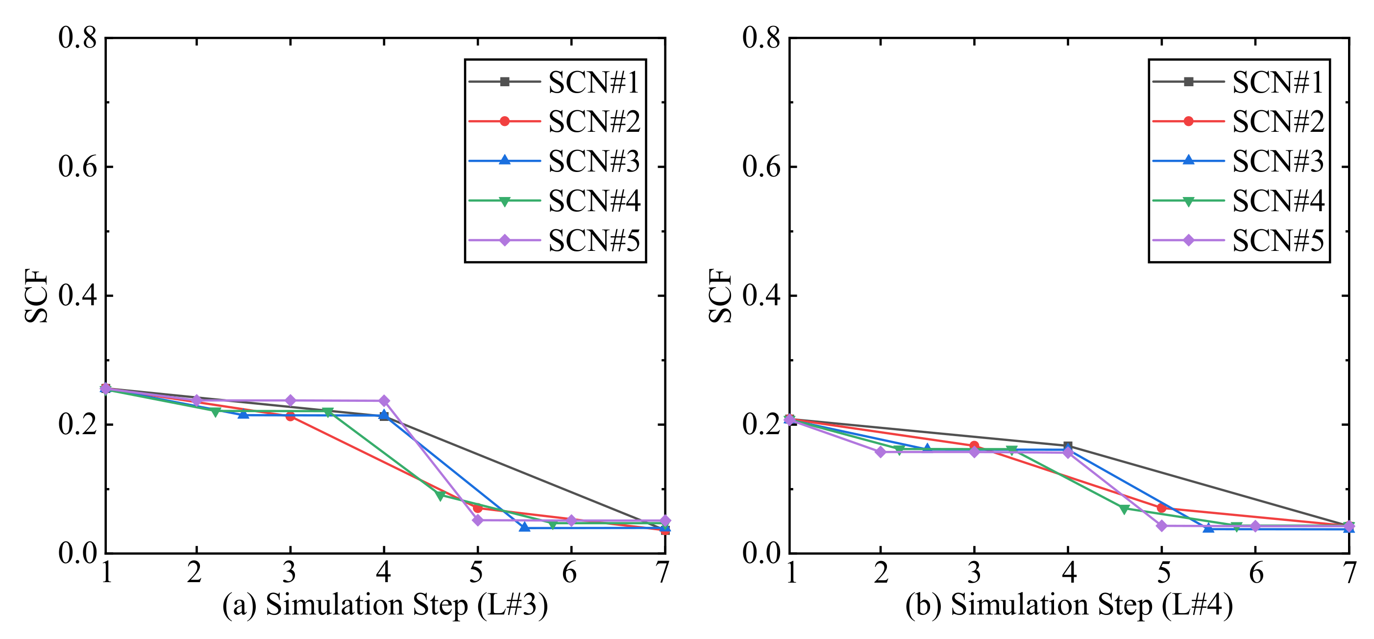
Similar to the major principal stress trend, the initial stress concentration factors of the sidewalls in level #3 and level #4 are smaller than those of the two deeper mining levels, as shown in Figure 8. For the scenarios SCN-1 and SCN-2 at both levels, the sidewall stress concentration factor witnesses a constant decrease, and the decreasing amplitude is larger when the backfilled CRF takes into effect. Before the backfilled CRF takes effect, the sidewall stress concentration factor keeps almost constant in SCN-3, SCN-4, SCN-5 at both level #3 and level #4. After the backfilling body takes effect, the sidewall stress concentration factor sees a dramatic decrease and keeps constant. Level # 3 has a 78% decrease from Step1 to Step7, and level #4 achieves a 79% decrease.
According to the above results of the sidewall stress concentration factor in the four different mining levels, the backfilling bodies can effectively reduce the stress concentration effect. After the backfilling bodies take into effect, the stress concentration factor will decrease to a value under 0.1, which means the backfilling bodies can effectively prevent the possible failure of the sidewall and improve the safety in the stopes. Furthermore, the decreasing amplitude of the sidewall stress concentration factor has an increasing trend when the mining level becomes shallower; even the differences among the four decreasing amplitudes are very close.
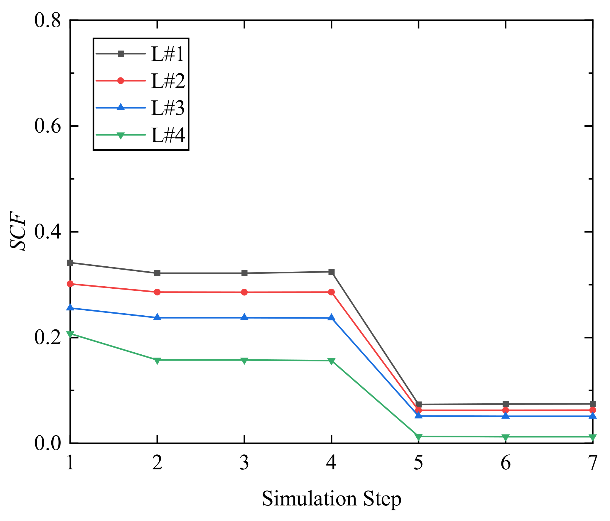
Figure 9 presents an example comparison of the stress concentration factor of SCN-5 among the four mining levels. The stress concentration factor strongly correlates with the mining level depth before the backfilling bodies take into effect. The shallower the mining level, the smaller the sidewall stress concentration factor. After the backfilling bodies take into effect at Step 4, the relation between the stress concentration factor and the mining level depth is weak. All four mining levels see a sharp decrease of the sidewall stress concentration factor after the backfilling is finished. All the four sidewall stress concentration factors will be under 0.1 and keep constant. From Figure 9, it can be concluded that using backfilling CRF of the same strength at different mining depths is acceptable and feasible to improve the stability of the stopes.
4. Discussion
In the actual process of backfilling at the case study mine, there are some limitations in backfilling the stopes voids such as (i) the inability of stope being entirely backfilled without voids at the top of the stope voids, (ii) different CRF mechanical properties at a different part of the backfill column caused by the non-uniform particle size distribution and the process of delivery and dumping, and (iii) the curing time [11] at each stope. This paper presents the study based on an assumption of the ideal mode of underground backfilling; then, the limitations are minimized.
From the above analysis of the sidewall displacement, mining-induced redistributed major principal stress, and the sidewall stress concentration factor (SCF), backfilling scenario SCN-1 is the optimum among these five different backfilling scenarios.
Considering the final status of sidewall displacement, major principal stress, and sidewall stress concentration factor, the backfilling process of scenario SCN-1 can be done in a shorter period compared with the other four backfilling scenarios, which will save time for the following mining activities and release the tension between the preparation and mining.
Meanwhile, compared with the other four backfilling scenarios, scenario SCN-1 will immediately provide adequate support to the adjacent stopes and prevent the possible failure caused by the delayed backfilling, thereby improving the stope stability and global mining stability.
From the decreasing percentage of the mining-induced redistributed major principal stress from before-excavation to after-backfilling these four mining levels, the same type of backfilling CRF with the same strength and elastic properties can achieve almost the same effect in lowering the major principal stress even at different mining depths. In decreasing the sidewall stress concentration factor (SCF), the same type of backfilling CRF achieves very close decreasing amplitude, even with mining depths. Using the same type of backfilling CRF at different mining depths can result from the same effect in improving the stability of the underground mining stopes.
5. Conclusions
By comparing the displacement, major principal stress, and stress concentration factor caused by the excavation, backfilling with CRF is an effective method to prevent possible failures and improve the safety of the underground mining stopes.
With the backfilling bodies taking into effect, the sidewall displacement sees no more increases compared with the sharp increases caused by the excavation. Therefore, the five different backfilling scenarios result in almost the same final displacement status. Furthermore, by stopping the increase of the sidewall displacement, the backfilling bodies prevent the possible sidewall failure, which provides better conditions for the following mining schedule.
The sidewall major principal stress release caused by the excavation sees a dramatic plunge with the effect of the backfilling CRF bodies. This is because the backfilling CRF bodies share the mining-induced redistributed stresses with the adjacent rock mass. Therefore, compared with the other four backfilling scenarios, scenario SCN-1 presents a constant decrease of the sidewall major principal stress with excavation and backfill and achieves a very low-value status among the four different mining levels.
As a critical factor in assessing the stope sidewall stability, the stress concentration factor (SCF) of each mining level proves that the backfilling CRF bodies effectively reduce the stress concentration effect on the sidewalls. Thus, by lowering the sidewall stress concentration factor, the backfilling CRF bodies improve the stability of the adjacent stopes for the following mining scheme.
Among the five different backfilling scenarios, the backfilling scenario SCN-1 is the optimum method among these five scenarios. By applying the SCN-1 backfilling strategy, the displacement will keep constant and stop increasing, thus preventing possible failures in stopes. Even after the excavation, the major principal stress shows a decreasing trend, while SCN-1 will achieve a minimum status quickly. The use of the same type of backfilled CRF achieves good results at different mining levels. Using the same type of backfilled CRF at different mining depths is acceptable and feasible to improve the stability of the underground mining stopes.
Author Contributions
Conceptualization, H.X. and D.B.A.; methodology, H.X. and J.W.; software, H.X.; validation, H.X., J.W. and C.W.; formal analysis, H.X.; investigation, H.X.; resources, H.X.; data curation, H.X.; writing—original draft preparation, H.X.; writing—review and editing, D.B.A. and Y.P.; visualization, H.X.; supervision, D.B.A.; project administration, D.B.A.; funding acquisition, D.B.A. All authors have read and agreed to the published version of the manuscript.
Funding
Natural Sciences and Engineering Research Council of Canada (NSERC) under the Collaborative Research and Development (CRD) Grant (NSERC RGPIN-2019-04572).
Data Availability Statement
Not Applicable.
Acknowledgments
This study was supported by the Natural Sciences and Engineering Research Council of Canada (NSERC) under the Collaborative Research and Development (CRD) Grant (NSERC RGPIN-2019-04572). The supports from China Scholarship Council were acknowledged. The supports from WestGrid and Compute/Calcul Canada were gratefully acknowledged.
Conflicts of Interest
The authors declare no conflict of interest.
References
- Hassani, F.; Archibald, J. Mine Backfill; Canadian Institue of Mining, Metallurgy, and Petroleum: Montreal, QC, Canada, 1998. [Google Scholar]
- Parviz, N.F. Improving Cemented Rockfill Design in Open Stoping. Ph.D. Thesis, McGill University, Montréal, QC, Canada, 1996. [Google Scholar]
- Brechtel, C.E.; Struble, G.R.; Guenther, B. The evaluation of cemented rockfill spans at the Murray Mine. In Proceedings of the 37th U.S. Symposium on Rock Mechanics (USRMS), Vail, CO, USA, 7–9 June 1999; pp. 481–487. [Google Scholar]
- Grice, A.G. Fill Research at Mount Isa Mines Limited. In Proceedings of the 4th International Symposium on Mining with Backfill, Montréal, QC, Canada, 2–5 October 1989; pp. 1–7. [Google Scholar]
- Cordova, M.; Saw, H.; Villaescusa, E. Laboratory Testing of Cemented Rock Fill for Open Stope Support. In Proceedings of the 7th International Conference & Exibition on Mass Mining, Sydney, NSW, Australia, 9–11 May 2016; pp. 9–11. [Google Scholar]
- Emad, M.Z.; Mitri, H.; Kelly, C. State-of-the-art review of backfill practices for sublevel stoping system. Int. J. Min. Reclam. Environ. 2014, 1–13. [Google Scholar] [CrossRef]
- Reschke, A.E. The use of cemented rockfill at Namew Lake mine, Manitoba, Canada. In Proceedings of the 5th International Symposium on Mining with Backfill, Johannesburg, South Africa, 13–15 September 1993; pp. 101–108. [Google Scholar] [CrossRef]
- Shrestha, B.K.; Tannant, D.D.; Proskin, S.; Greer, J.R. Properties of cemented rockfill used in an open pit mine. In Proceedings of the GeoEdmonton’08: 61st Canadian Geotechnical Conference and 9th Joint CGS/IAH-CNC Groundwater Conference: Conference Proceedings, Edmonton, AB, Canada, 21–24 September 2008; pp. 609–616. [Google Scholar]
- Yu, T.R.; Counter, D.B. Backfill practice and technology at Kidd Creek Mines. CIM Bull. 1983, 76, 56–65. [Google Scholar] [CrossRef]
- Saw, H.A.; Prentice, S.; Villaescusa, E. Characterisation of cemented rock fill materials for the Cosmos nickel mine, Western Australia. In Proceedings of the International Conference on Advances in Construction Materials through Science and Engineering, Hong Kong, China, 5–7 September 2011. [Google Scholar]
- Lingga, B.A. Investigation of Cemented Rockfill Properties Used at a Canadian Diamond Mine. Master’s Thesis, University of Alberta, Edmonton, AB, Canada, 2018. [Google Scholar]
- Lingga, B.A.; Apel, D.B. Shear properties of cemented rockfills. J. Rock Mech. Geotech. Eng. 2018, 10, 635–644. [Google Scholar] [CrossRef]
- Lingga, B.A.; Apel, D.B.; Sepehri, M.; Pu, Y. Assessment of digital image correlation method in determining large scale cemented rockfill strains. Int. J. Min. Sci. Technol. 2019, 29, 771–776. [Google Scholar] [CrossRef]
- Stone, D.M.R. Factors that affect cemented rockfill quality in Nevada mines. In Proceedings of the Ninth International Symposium on Mining with Backfill (Minefill 2007), Montreal, QC, Canada, 29 April–3 May 2007; Volume 100. [Google Scholar]
- Helinski, M.; Fahey, M.; Fourie, A. Numerical Modeling of Cemented Mine Backfill Deposition. J. Geotech. Geoenviron. Eng. 2007, 133, 1308–1319. [Google Scholar] [CrossRef] [Green Version]
- Helinski, M.; Fahey, M.; Fourie, A. Behavior of Cemented Paste Backfill in Two Mine Stopes: Measurements and Modeling. J. Geotech. Geoenivron. Eng. 2011, 137, 171–182. [Google Scholar] [CrossRef]
- Fahey, M.; Helinski, M.; Fourie, A. Some aspects of the mechanics of arching in backfilled stopes. Can. Geotech. J. 2009, 46, 1322–1336. [Google Scholar] [CrossRef]
- Gibson, R.E. The progress of consolidation in a clay layer increasing in thickness with time. Geotechnique 1958, 8, 171–182. [Google Scholar] [CrossRef]
- Emad, M.Z.; Mitri, H.; Henning, J.G. Effect of blast vibrations on the stability of cemented rockfill. Int. J. Min. Reclam. Environ. 2012, 26, 233–243. [Google Scholar] [CrossRef]
- Emad, M.Z.; Mitri, H.; Kelly, C. In-situ blast vibration monitoring in cemented rockfill stope—A case study. Int. J. Min. Reclam. Environ. 2017, 930, 119–136. [Google Scholar] [CrossRef]
- Emad, M.Z.; Mitri, H.; Kelly, C. Effect of blast-induced vibrations on fill failure in vertical block mining with delayed backfill. Can. Geotech. J. 2014, 51, 975–983. [Google Scholar] [CrossRef]
- Henning, J.; Mitri, H. Production blast-induced vibrations in longhole open stoping: A case study. Int. J. Geotech. Earthq. Eng. 2010, 1, 1–11. [Google Scholar] [CrossRef] [Green Version]
- Thompson, B.D.; Grabinsky, M.W.; Bawden, W.F.; Counter, D.B. In-situ measurements of cemented paste backfill in long-hole stopes. In Proceedings of the RockEng09: Proceedings of the 3rd CANUS Rock Mechanics Symposium, Toronto, ON, USA, 9–15 May 2009; Volume 2009, pp. 1–10. [Google Scholar]
- Thompson, B.D.; Hunt, T.; Malek, F.; Grabinsky, M.W.; Bawden, W.F. In situ behaviour of cemented hydraulic and paste backfills and the use of instrumentation in optimising efficiency. In Proceedings of the 11th International Symposium on Mining with Backfill, Perth, WA, Australia, 20–22 May 2014; pp. 337–350. [Google Scholar]
- Thompson, B.D.; Bawden, W.F.; Grabinsky, M.W. In situ measurements of cemented paste backfill at the Cayeli Mine. Can. Geotech. J. 2012, 772, 755–772. [Google Scholar] [CrossRef]
- Kumar, D.; Singh, U.K.; Singh, G.S.P. Laboratory Characterization of Cemented Rock Fill for Underhand Cut and Fill Method of Mining. J. Inst. Eng. Ser. D 2016, 97, 193–203. [Google Scholar] [CrossRef]
- Seymour, B.; Larson, M.K. Stability of backfilled cross-panel entries during longwall. In Proceedings of the 17th Conference on Ground Control in Mining, Morgantown, WV, USA, 4–6 August 1998. [Google Scholar]
- Seymour, J.B.; Raffaldi, M.J.; Warren, S.N.; Martin, L.A.; Sandbak, L.A. Long-term stability of a large undercut span beneath cemented rockfill at the turquoise ridge mine. In Proceedings of the 52nd Rock Mechanics/Geomechanics Symposium, Seattle, WA, USA, 17–20 June 2018. [Google Scholar]
- Tesarik, D.R.; Seymour, J.B.; Martin, L.A.; Jones, F.M. Numeric model of a cemented rockfill span test at the Turquoise Ridge Mine, Golconda, Nevada, USA. In Proceedings of the Ninth International Symposium on Mining with Backfill (Minefill 2007), Montreal, QC, Canada, 29 April–3 May 2007. [Google Scholar]
- Tesarik, D.R.; Seymour, J.B.; Jones, F.M. Determination of in situ deformation modulus for cemented rockfill. In Proceedings of the ISRM 2003–Technology Roadmap for Rock Mechanics, Johannesburg, South Africa, 8–12 September 2003; pp. 1209–1220. [Google Scholar]
- Ramelius, P.M.; Pty, R.; Mikula, P.A.M.; Pty, G. Shotcrete ribs and cemented rock fill ground control methods for stoping in weak squeezing rock at Wattle Dam Gold Mine. In Proceedings of the 7th International Symposium on Ground Support in Mining and Underground Construction, Perth, WA, Australia, 13–15 May 2013; pp. 133–148. [Google Scholar] [CrossRef]
- Sainsbury, D.; Sainsbury, B.A. Design and implementation of cemented rockfill at the Ballarat Gold Project. In Proceedings of the Eleventh International Symposium on Mining with Backfill, Perth, WA, Australia, 20–22 May 2014; pp. 205–216. [Google Scholar] [CrossRef]
- Sainsbury, B.; Sainsbury, D.; Western, J.; Petrie, P.; Mutton, V. Pillar recovery adjacent to stabilised rockfill at the Ballarat Gold Project. In Proceedings of the 3rd Australian Ground Control in Mining Conference (AusRock 2014), Sydney, NSW, Australia, 5–6 November 2014; paper no. 29. pp. 1–18. [Google Scholar]
- Potvin, Y.; Hadjigeorgiou, J. Ground support strategies to control large deformations in mining excavation. J. S. Afr. Inst. Min. Metall. 2008, 108, 393–400. [Google Scholar]
- Beck, D.; Kassbohm, S.; Putzar, G. Multi-scale simulation of ground support designs for extreme tunnel closure. In Proceedings of the Second International Symposium on Block and Sublevel Caving, Perth, WA, Australia, 20–22 April 2010; pp. 441–454. [Google Scholar]
- Mercier-Langevin, F.; Hadjigeorgiou, J. Towards a better understanding of squeezing potential in hard rock mines. Min. Technol. 2011, 120, 36–44. [Google Scholar] [CrossRef]
- Wang, J.; Apel, D.B.; Pu, Y.; Hall, R.; Wei, C.; Sepehri, M. Numerical modeling for rockbursts: A state-of-the-art review. J. Rock Mech. Geotech. 2021, 13, 457–478. [Google Scholar] [CrossRef]
- Grabinsky, M.W. In situ monitoring for ground truthing paste backfill designs. In Proceedings of the 13th International Seminar on Paste and Thickened Tailings, Perth, WA, Australia, 3–6 May 2010; pp. 85–98. [Google Scholar]
- Mitri, H.S. Assessment of horizontal pillar burst in deep hard rock mines. Int. J. Risk Assess. Manag. 2007, 7, 695–707. [Google Scholar] [CrossRef]
- Pu, Y.; Apel, D.B.; Xu, H. Rockburst prediction in kimberlite with unsupervised learning method and support vector classifier. Tunn. Undergr. Space Technol. 2019, 90, 12–18. [Google Scholar] [CrossRef]
- Doerner, C.A.C. Effect of Delayed Backfill on Open Stope Mining Methods. Master’s Thesis, The University of British Columbia, Vancouver, BC, Canada, 2005. [Google Scholar]
- Sepehri, M. Finite Element Analysis Model for Determination of In-Situ and Mining Induced Stresses as a Function of Two Different Mining Methods Used at Diavik Diamond Mine. Ph.D. Thesis, University of Alberta, Edmonton, AB, Canada, 2016. [Google Scholar]
- Sepehri, M.; Apel, D.B.; Hall, R.A. Prediction of mining-induced surface subsidence and ground movements at a Canadian diamond mine using an elastoplastic finite element model. Int. J. Rock Mech. Min. Sci. 2017, 100, 73–82. [Google Scholar] [CrossRef]
- Sepehri, M.; Apel, D.B.; Adeeb, S.; Leveille, P.; Hall, R.A. Evaluation of mining-induced energy and rockburst prediction at a diamond mine in Canada using a full 3D elastoplastic finite element model. Eng. Geol. 2020, 266, 105457. [Google Scholar] [CrossRef]
- Sun, Y.; Chen, Y.; Wang, Z. Numerical simulation of inner support for excavation based on FEM software ABAQUS. Appl. Mech. Mater. 2012, 236, 632–635. [Google Scholar] [CrossRef]
- Dassault Systèmes Simulia Corp. Analysis User’s Manual Volume 1: Introduction, Spatial Modeling, Execution and Output; Abaqus 6.12; SIMULIA: Johnston, RI, USA, 2012; Volume I. [Google Scholar]
- Labuz, J.F.; Arno, Z. Mohr-Coulomb failure criterion. In The ISRM Suggested Methods for Rock Characterization, Testing and Monitoring: 2007–2014; Springer: Berlin/Heidelberg, Germany, 2014; pp. 227–231. [Google Scholar]
- Wiseman, N. Factors affecting the design and condition of mine tunnels. Chamb. Mine S. Afr. 1979. [Google Scholar] [CrossRef]
Figure 1.
FEM model of the mine site and element mesh type.

Figure 2.
Profile of stope P1–133 and five backfilling step scenarios.

Figure 3.
Displacement of sidewall middle of level #1 and level #2.

Figure 4.
Displacement of sidewall middle of level #3 and level #4.

Figure 5.
Major principal stress of sidewall middle of level #1 and level #2.

Figure 6.
Major principal stress of sidewall middle of level #3 and level #4.

Figure 7.
SCF of sidewall middle of level #1 and level #2.

Figure 8.
SCF of sidewall middle of level #3 and level #4.

Figure 9.
Comparison of SCF of SCN-5 among four mining levels.


Table 1.
Material properties.
| Material | E (MPa) | C (MPa) | Φ (°) | γ (MN/m3) | ν | σc (MPa) |
|---|---|---|---|---|---|---|
| MP#1 | 18.7 × 10³ | 4.2 | 26.4 | 0.024 | 0.26 | 66 |
| Granite | 24 × 103 | 9.3 | 45 | 0.026 | 0.3 | 130 |
| Backfilled CRF | 2 × 10³ | 1.2 | 35 | 0.022 | 0.3 | 1.5 |
Table 2.
Five different backfilling scenarios.
| Scenario | BF1 | BF2 | BF3 | BF4 | BF5 | Step |
|---|---|---|---|---|---|---|
| SCN-1 | Y | N | N | N | N | 3 |
| SCN-2 | Y | Y | N | N | N | 4 |
| SCN-3 | Y | Y | Y | N | N | 5 |
| SCN-4 | Y | Y | Y | Y | N | 6 |
| SCN-5 | Y | Y | Y | Y | Y | 7 |
Note: Here, Y means yes; N means no; step means the steps needed to complete the simulation.
Publisher’s Note: MDPI stays neutral with regard to jurisdictional claims in published maps and institutional affiliations. |
© 2021 by the authors. Licensee MDPI, Basel, Switzerland. This article is an open access article distributed under the terms and conditions of the Creative Commons Attribution (CC BY) license (https://creativecommons.org/licenses/by/4.0/).
Share and Cite
MDPI and ACS Style
Xu, H.; Apel, D.B.; Wang, J.; Wei, C.; Pourrahimian, Y. Investigation of Backfilling Step Effects on Stope Stability. Mining 2021, 1, 155-166. https://0-doi-org.brum.beds.ac.uk/10.3390/mining1020010
AMA Style
Xu H, Apel DB, Wang J, Wei C, Pourrahimian Y. Investigation of Backfilling Step Effects on Stope Stability. Mining. 2021; 1(2):155-166. https://0-doi-org.brum.beds.ac.uk/10.3390/mining1020010
Chicago/Turabian StyleXu, Huawei, Derek B. Apel, Jun Wang, Chong Wei, and Yashar Pourrahimian. 2021. "Investigation of Backfilling Step Effects on Stope Stability" Mining 1, no. 2: 155-166. https://0-doi-org.brum.beds.ac.uk/10.3390/mining1020010