
Ag Nanoparticle-Decorated MoS2 Nanosheets for Enhancing Electrochemical Performance in Lithium Storage


Department of Chemical and Biological Engineering, Gachon University, Seongnam-si 13120, Gyeonggi-do, Korea
*
Author to whom correspondence should be addressed.
Nanomaterials 2021, 11(3), 626; https://0-doi-org.brum.beds.ac.uk/10.3390/nano11030626
Submission received: 5 February 2021
/
Revised: 23 February 2021
/
Accepted: 27 February 2021
/
Published: 3 March 2021
(This article belongs to the Special Issue Nanomaterials for Ion Battery Applications)
Abstract
:Metallic phase 1T MoS2 is a well-known potential anode for enhancing the electrochemical performance of lithium-ion batteries owing to its mechanical/chemical stability and high conductivity. However, during the lithiation/delithiation process, MoS2 nanosheets (NSs) tend to restack to form bulky structures that deteriorate the cycling performance of bare MoS2 anodes. In this study, we prepared Ag nanoparticle (NP)-decorated 1T MoS2 NSs via a liquid exfoliation method with lithium intercalation and simple reduction of AgNO3 in NaBH4. Ag NPs were uniformly distributed on the MoS2 surface with the assistance of 3-mercapto propionic acid. Ag NPs with the size of a few nanometers enhanced the conductivity of the MoS2 NS and improved the electrochemical performance of the MoS2 anode. Specifically, the anode designated as Ag3@MoS2 (prepared with AgNO3 and MoS2 in a weight ratio of 1:10) exhibited the best cycling performance and delivered a reversible specific capacity of 510 mAh·g−1 (approximately 73% of the initial capacity) after 100 cycles. Moreover, the rate performance of this sample had a remarkable recovery capacity of ~100% when the current decreased from 1 to 0.1 A·g−1. The results indicate that the Ag nanoparticle-decorated 1T MoS2 can be employed as a high-rate capacity anode in lithium-ion storage applications.
1. Introduction
Recently, there has been increasing interest among researchers in transition metal chalcogenides (TMCs), which are graphene-like two-dimensional (2D) materials consisting of a transition metal atom layer sandwiched between two chalcogenide atom layers. Each monolayer of TMC is formed as a 2D structured layer, and these layers are bonded to each other by van der Waals forces in the bulk structure. Therefore, the TMCs can be easily exfoliated into a single layer or a few layers. Moreover, various properties of these 2D materials have been investigated, and they have been found to be superior to bulk materials in strength, physical and chemical stability, and conductivity [1,2,3,4]. Therefore, TMCs have been employed in several electronic, optical, and energy conversion/storage applications, for example, in energy applications such as solar cells, light emitting diodes, hydrogen evolution reactions, and metal-ion batteries [5,6,7,8,9,10,11,12]. Among TMC materials, MoS2 shows great potential for easy processing and high stability. Therefore, numerous studies have reported on its characteristics and applications. In particular, with a direct band-gap structure, the 1T phase of MoS2 nanosheets (NSs) is attractive owing to its high mechanical/chemical stability and high conductivity [13,14,15,16]. Recently, MoS2 NSs have been used as potential candidates for anodes in lithium-ion batteries (LIBs) [17,18,19,20,21,22]. With a nanosheet structure, MoS2 has a large surface area and flexibility for the lithiation and delithiation processes and enhances the electrochemical performance of LIBs. Furthermore, the 1T phase of MoS2, with metallic properties, can afford high conductivity, which facilitates the processes of lithiation and delithiation. Various methods have been used to enhance the electrochemical performance of MoS2 in LIBs by using metals doping, metal particles or metal oxides. Zhu et al. used TiO2 nanoparticles (NPs) decorating on 2H- MoS2 NS via hydrothermal method to achieve the reversible capacity of 604 mAh·g−1 after 100 cycles [23]. Pan et al. developed Ag methanesulfonic-acid capped NPs with 2H-MoS2 NSs by sonication method to get high reversible capacity of ~920 mAh·g−1 after 50 cycles [24]. In addition, Li et al. synthesized lithium molten salt of MoS2 as a precursor at 1050 °C for liquid exfoliation of 1T MoS2 [25]. This report showed that the superior properties of 1T MoS2 to 2H MoS2 due to the existence of abundant monolayer structures, providing diffusion path for lithium ion insertion/desertion. Wang et al. reported vertically aligned MoS2 NSs patterned on graphene for LIBs, which exhibited high-rate energy storage [26]. This structure also enables sodium-ion storage capability. Tang et al. developed hollow 1T MoS2 grown on carbon cloth and demonstrated high rate performance, high capacity, and good stability in sodium-ion batteries [27]. Li et al. combined 1T MoS2 with MnO in lithium molten salts assisted with a ball milling method to develop a high-stability LIB anode. This MoS2/MnO composite anode retained a high capacity of ~589 mAh·g−1 after 2000 cycles [28]. Bai et al. fabricated a 1T MoS2/C hybrid anode material through a hydrothermal method [20]. These carbon-covered MoS2 NS materials also exhibited a high rate performance in LIBs. Therefore, 1T phase MoS2 could be a potential anode for high capacity and high rate performance in LIBs. However, the commercialization of MoS2 anode materials requires an easy fabrication process and further improvement in stability and rate performance.
In this study, we successfully investigated Ag NP-decorated 1T MoS2 nanosheets as a potential anode for high-rate performance and stable LIBs. MoS2 was prepared by a liquid chemical exfoliation method with lithium intercalation. By adding 3-mercapto propionic acid (MPA) as a functional group, Ag NPs were uniformly decorated on the MoS2 surface. The presence of Ag NPs not only improves the specific capacity but also significantly enhances the rate performance and stability of the anode material in lithium storage. Notably, the Ag3@MoS2 anode can restore ~100% capacity after high-rate cycling.
2. Materials and Methods
2.1. Chemical Materials
Molybdenum (IV) sulfide (MoS2, powder), silver nitrate (AgNO3, 99%), MPA (99%), polyvinylidene fluoride (PVDF, MW 534,000), N-methyl-2-pyrrolidinone (NVP, anhydrous, 99.5%), and a 2.5 M solution of n-butyllithium ion hexane and sodium borohydride (NaBH4, 99%) were purchased from Sigma-Aldrich Inc. (St. Louis, MO, USA). Super P amorphous carbon black (C, approximately 40 nm, 99.99%) was purchased from Alpha Aesar Inc. (Haverhill, MA, USA).
2.2. Synthesis MoS2 NSs
MoS2 NSs were prepared as described in our previous report [17]. The loading of butyllithium was conducted in Ar-filled glovebox to prevent the reactions between butyllithium and oxygen/moister. First, 1.0 g of MoS2 powder was added to 3 mL of 2.5 M butyllithium in hexane. Then, the solution was sealed with parafilm, taken out to be sonicated for 1 h, and kept for two days to obtain lithium-intercalated MoS2 (LixMoS2) in glove box. The excess lithium was removed by washing with hexane. The obtained LixMoS2 was placed in 100 mL of deionized (DI) water. The interlayer lithium reacted with DI water to break the layer structure of the bulk MoS2 and form MoS2 NSs. The solution was further sonicated for 1 h and stirred for 1 h to obtain a complete dispersion of the MoS2 NS. Finally, the dispersion was centrifuged and washed four times to remove excess lithium.
2.3. Ag-Decorated MoS2 NS
The surface of the NSs was modified by MPA in order to obtain Ag-decorated MoS2 NSs. The prepared LixMoS2, after being washed with hexane, was added to 100 mL of 0.045 M MPA solution. This process was similar to the synthesis of MoS2 NSs. After sonication and washing with DI water, MPA-modified MoS2 NSs were redispersed in DI water via sonication. Then, amounts of AgNO3 with different weight ratios (1:50, 1: 20, and 1:10) to MoS2 were added to the solution during stirring, and the samples were denoted as Ag1@MoS2, Ag2@MoS2, and Ag3@MoS2, respectively. Naturally, MPA contains both thiol and carboxyl groups. The thiol group is able to exchange with the S atom on MoS2 with the appearance of Li ions [29,30]. Meanwhile, the carboxyl group induces a partial negative charge, which attracts Ag+ ions in the solution. Then, a solution of 0.5 M NaBH4 was added to the aforementioned solution to reduce Ag+ to Ag nanoparticles. The solution was further washed via centrifugation with DI water three times to remove NaBO2. The final product was obtained after drying at 70 °C for 12 h.
2.4. Characterization
Scanning electron microscopy (SEM; Hitachi S4700, Tokyo, Japan) and transmission electron microscopy (TEM; TECNAI G2F30, FEI Corp., Hillsboro, OR, USA) were used to analyze the morphologies and sizes of the as-prepared materials. Samples were coated a few-nanometers Pt layer via magnetron sputtering system for high quality SEM images. A high-resolution X-ray diffractometer (XRD; SmartLab, Rigaku, Tokyo, Japan) was used to investigate material structures. XRD patterns were recorded over the 2θ range 10–70°.
2.5. Electrochemical Measurements
Anode materials were assembled in a half-cell LIB using coin-type cells (CR 2032, Rotech Inc., Gwangju, Korea). Typically, the anode electrode was prepared using a doctor blade on a Cu foil using a slurry of 70% active material, 15% PVDF, and 15% Super P in NVP. Then, the electrodes were dried in a vacuum oven at 70 °C for 24 h before use. The anodes were punched into 12 mm diameter circular disks. The loading of active materials was ~0.7–1.0 mg cm−2. Then, battery half-cell structures were assembled in an Ar-filled glovebox with positive pressure (>1.0 atm). Lithium foil and polyethylene were used as the reference electrode and separator, respectively. A solution of 1 M LiPF6 in ethylene carbonate-diethylene carbonate (1:1 by volume) was employed as the electrolyte. Galvanostatic electrochemical discharge/charge analysis of the different cells was performed using a battery cycle tester (WBCS3000, WonAtech Co., Ltd., Seocho-gu, Seoul, Korea) over the voltage range 0.01–3.00 V versus Li/Li+. Electrochemical impedance spectroscopy (EIS) and cyclic voltammetry (CV) tests were performed using a ZIVE MP1 apparatus (WonAtech Co., Ltd., Seocho-gu, Seoul, Korea). EIS measurements were recorded at 3.0 V over the frequency range between 100 kHz and 0.1 Hz. CV tests were performed over the voltage range 0.01–3.0 V at a scan rate of 0.1 mV·s−1.
3. Results and Discussion
The MoS2 NSs were fabricated using a liquid exfoliation method [17]. MoS2 bulk powder was mixed with butyllithium in hexane to form intercalated lithium ions in MoS2 as interlayer structures. The lithium ions easily filled the MoS2, forming inter-layers between two MoS2 layers by the following process:
According to Dines [31], the x value is in the range 1.1–1.5. This implies that the lithium ions easily fill the bulk MoS2. Then, reactions between the intercalated lithium and water create hydroxide ions and hydrogen gas. This reaction and the generated gas exfoliate the MoS2 layers. Finally, the bulk MoS2 is cleaved into MoS2 NSs.
Figure 1a,b are SEM images of exfoliated MoS2 NSs at different scale bars of 5 μm and 500 nm, respectively. The lateral size of the MoS2 NSs was between 100 nm and 3 μm. This wide range of MoS2 sizes is because of the strong reaction with Li(1) and the random shape of the bulk MoS2 powder. According to previous reports, the butyllithium intercalation process converts the 2H MoS2 to 1T due to the effect of lithium ion [10,32]. In this phase, the material could have high conductivity (10–100 S cm−1), which is about 105 times that of 2H-MoS2 [25,33]. Therefore, it is thought that highly conductive 1T MoS2 phase would generate different electrochemical performance (discussed later). Besides, AgNO3 was selected as the Ag source in order to decorate Ag nanoparticles on the MoS2. MoS2 NSs were functionalized by MPA to prevent random decoration and achieve uniform decoration. Using this functional group, metal ions are easily attracted to the partial negative charge of -COO− to uniformly distribute the Ag+ ions. Then, H2 generated by the hydrolysis of NaBH4 reduces Ag+ ions into Ag NPs, as illustrated in Figure 1c. Three samples with different AgNO3:MoS2 weight ratios—1:50, 1:20, and 1:10—were prepared, and, as aforementioned, they are designated herein as Ag1@MoS2, Ag2@MoS2, and Ag3@MoS2, respectively. Figure 1d, showing the Ag1@MoS2 sample and an inset image of its magnified surface, indicates that the surface of MoS2 has only a few Ag NPs owing to the small amount of Ag+ used. When the amount of AgNO3 was increased in Ag2@MoS2, the Ag NPs were more uniformly decorated with higher density. Figure 1e and its inset image show uniform Ag NPs on the MoS2 surface; however, they do not fully cover the surface. The 1:10 ratio of the Ag3@MoS2 sample reveals the highest coverage of Ag nanoparticles with a size of <10 nm on the MoS2 nanosheets, as shown in Figure 1f.
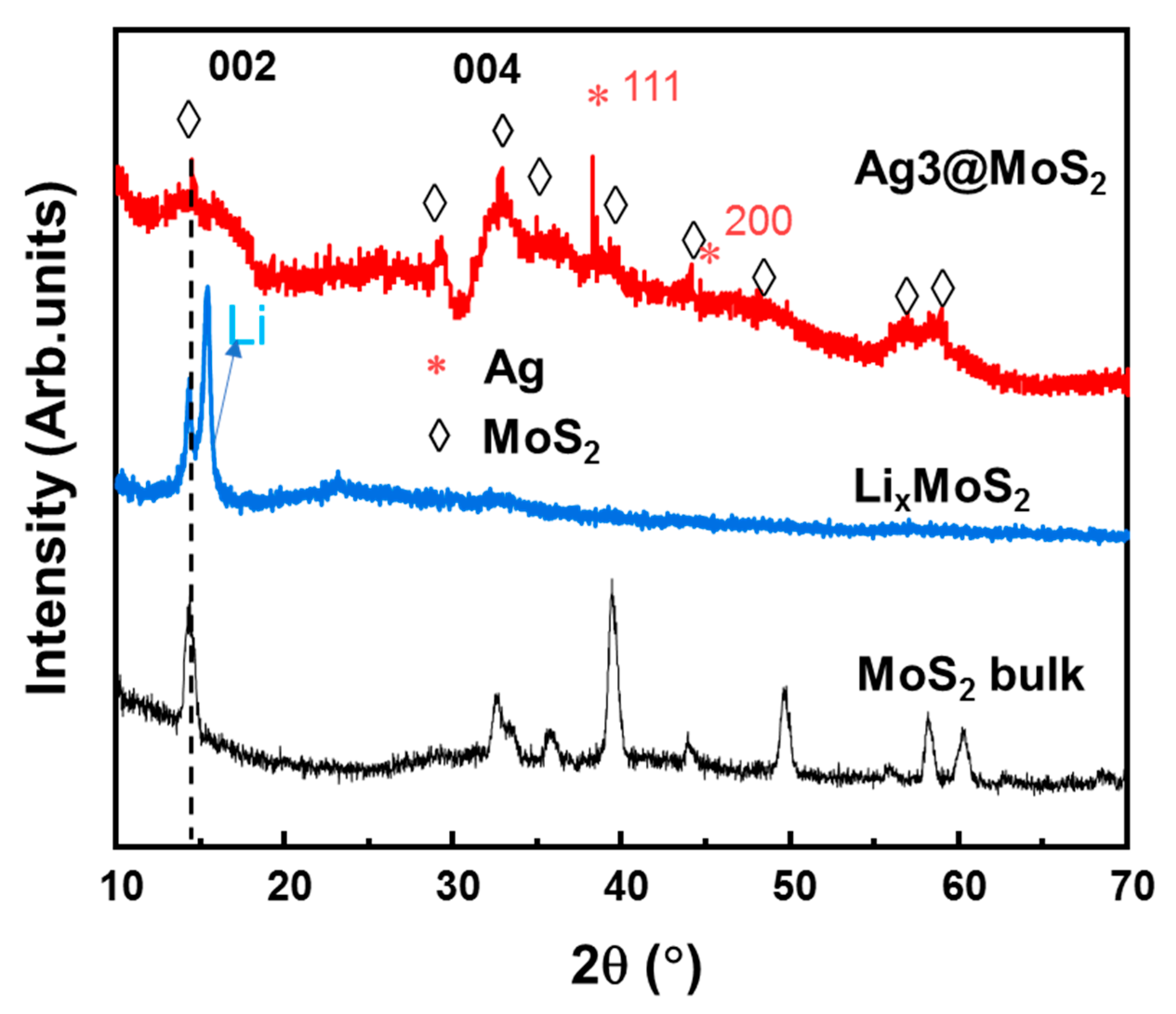
The structure of MoS2 and Ag-decorated MoS2 were analyzed by XRD. Figure 2 shows the XRD patterns of bulk MoS2, LixMoS2, and Ag-decorated MoS2 NSs. It is noted that the bulk MoS2 powder contains many peaks contributed by various planes in the lattice. However, after lithium ions are intercalated in the MoS2 layers, the XRD pattern of LixMoS2 has a main peak for the (002) plane of MoS2 at ~14.36° and a peak at 15.1°, which is related to the interlayer plane of Li between the MoS2 layers. The other peaks were much reduced and negligible due to the high intensity of (002) plane. After exfoliation and Ag decoration, the sample shows some main peaks for MoS2 at ~14.4°, ~29.0°, and 32.7°, which correspond to the (002), (004), and (100) planes according to the #JCPDS card number 00-037-1492. The XRD peaks of MoS2 are broadened in comparison to those of the bulk material. According to the Scherrer equation, the average size of the crystals can be calculated by D = 0.9λ/βcosθ, where D is the average size, λ is the X-ray wavelength, β is the full width at half maximum of the peak, and θ is the diffraction angle. Thus, the broadening of these peaks indicates small crystal sizes in those planes, which implies that the bulk MoS2 material was exfoliated into nanosheets. These results are similar to other synthesized MoS2 nanosheets by bottom-up methods such as hydrothermal method and hot injection method [34,35,36,37]. The appearance of Ag peaks for the (111) and (200) planes confirms the successful reduction of AgNO3 into Ag nanoparticles.
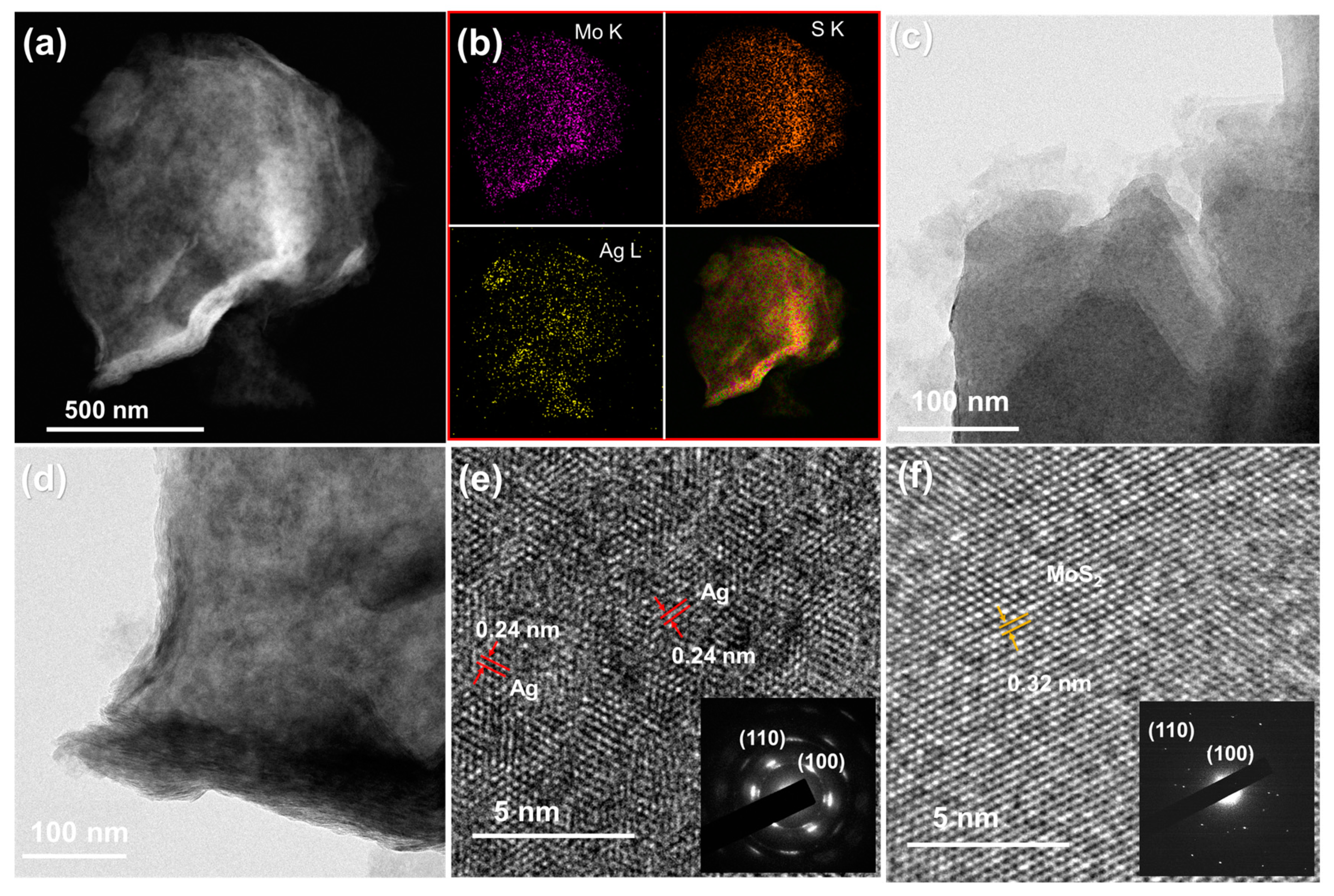
The structure of Ag-decorated MoS2 was further confirmed by TEM measurements. Figure 3a,b shows TEM images with individual and overlaid elemental mapping images of Mo (K), S (K), and Ag (L) elements. The Mo and S atoms are clearly shown with a high density of purple and orange colors, indicating the formation of MoS2 NSs. Ag atoms are uniformly distributed in the MoS2 area, confirming the successful decoration of Ag nanoparticles on MoS2. Figure 3c,f show TEM images and high-resolution TEM (HRTEM) images with an inset of the selected area electron diffraction (SAED) pattern of the MoS2 NSs. The MoS2 NS surface shows a clear lattice spacing distance of 0.32 nm, which corresponds to the (004) plane. Figure 3d,e shows TEM and HRTEM images of Ag3@MoS2 with an inset figure. The TEM image has many dark points representing Ag particles decorated on MoS2. The HRTEM image was also analyzed to reveal the lattice spacing of 0.24 nm resulting from the Ag lattice structure. The size of the Ag NPs is a few nanometers. The SAED pattern of the Ag-decorated sample is changed in comparison to that of the pure MoS2 sample. The pattern shows that the reflective planes reveal wide, blurred points, which could be because of the overlap of Ag NPs on the MoS2 NSs. The high uniformity of Ag decoration on MoS2 NSs is, thus, confirmed.
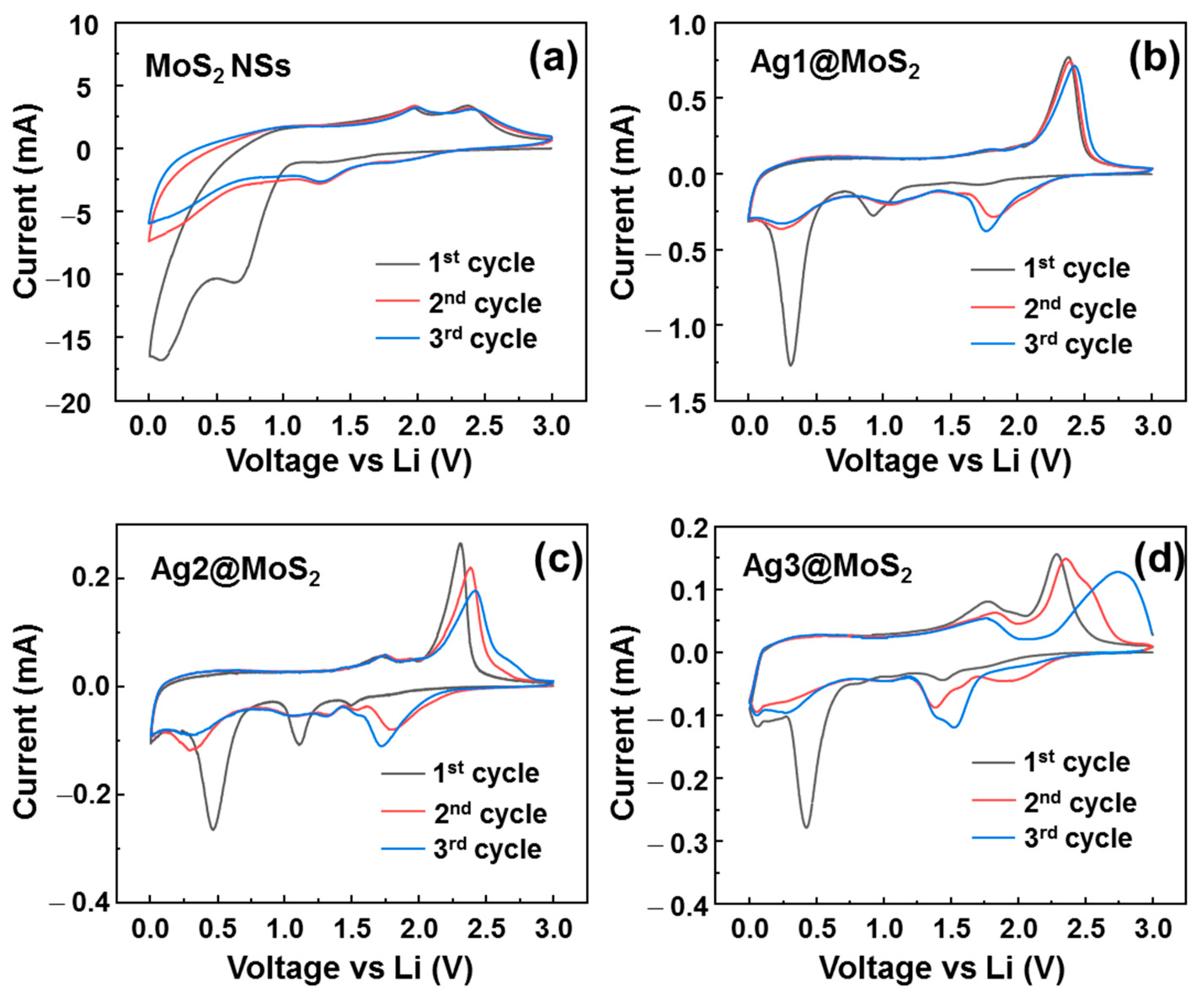
To investigate the effect of Ag-decorated MoS2 NSs on the electrochemical properties in lithium batteries, CV tests were performed at a scan rate of 0.1 mV·s−1 over the range 0.01–3.00 V (vs. Li/Li+). Figure 4a–d shows the initial three CV curves for MoS2 NSs and Ag1/2/3@MoS2 anodes. The electrochemical processes in the anode can be expressed by the following reactions:
In the cathodic process, the MoS2 NSs anode shows a peak at 1.3 V (vs. Li/Li+), which is the intercalation process of lithium ions into MoS2 NSs to form LixMoS2, corresponding to reaction (2) [26]. The strong peak at 0.5–1.0 V (vs. Li/Li+) is related to the strong formation of a solid electrolyte interface (SEI) layer and the transformation of LixMoS2 to metallic Mo nanoparticles and the Li2S conversion reaction, as shown in Equations (3) and (4) [17,19]. In the 2nd and 3rd cycles, the SEI layer is stable; therefore, the peak at 0.5–1.0 V is significantly reduced. The peak at 1.3 V is strong and stable, indicating stable lithium intercalation process. In the anodic process, the peaks at 1.8 and 2.3 V are associated with the oxidation of Mo to Mo+4 and the delithiation of Li2S to sulfur, respectively. In the case of the Ag1@MoS2 anode, the CV curves indicate some different electrochemical processes. The intercalation peak in the first cycle is shifted to ~1.0 V (vs. Li/Li+). The CV profiles mainly have two pairs of redox peaks at 1.1/1.7 V and 1.75/2.3 V, which are related to the multiple steps of lithiation and delithiation. When the amount of Ag is increased, the reduction peaks shift to higher potentials. In the Ag2@MoS2 anode, there are two pairs of redox peaks at 1.3/1.75 and 1.75/2.4 V. The peak at ~0.3 V is the formation of Ag–Li alloys [38]. The dealloying peak of Ag–Li is not shown as a clear peak; however, the hump at 0.2–0.5 V may indicate the multiple Ag–Li phases of the de-alloying process [38]. Notably, when the Ag content is increased, the oxidation peak position shifts to a higher potential, and the shape is broadened. This might be because of the enhanced multiple steps of the oxidation process for Li2S [39].
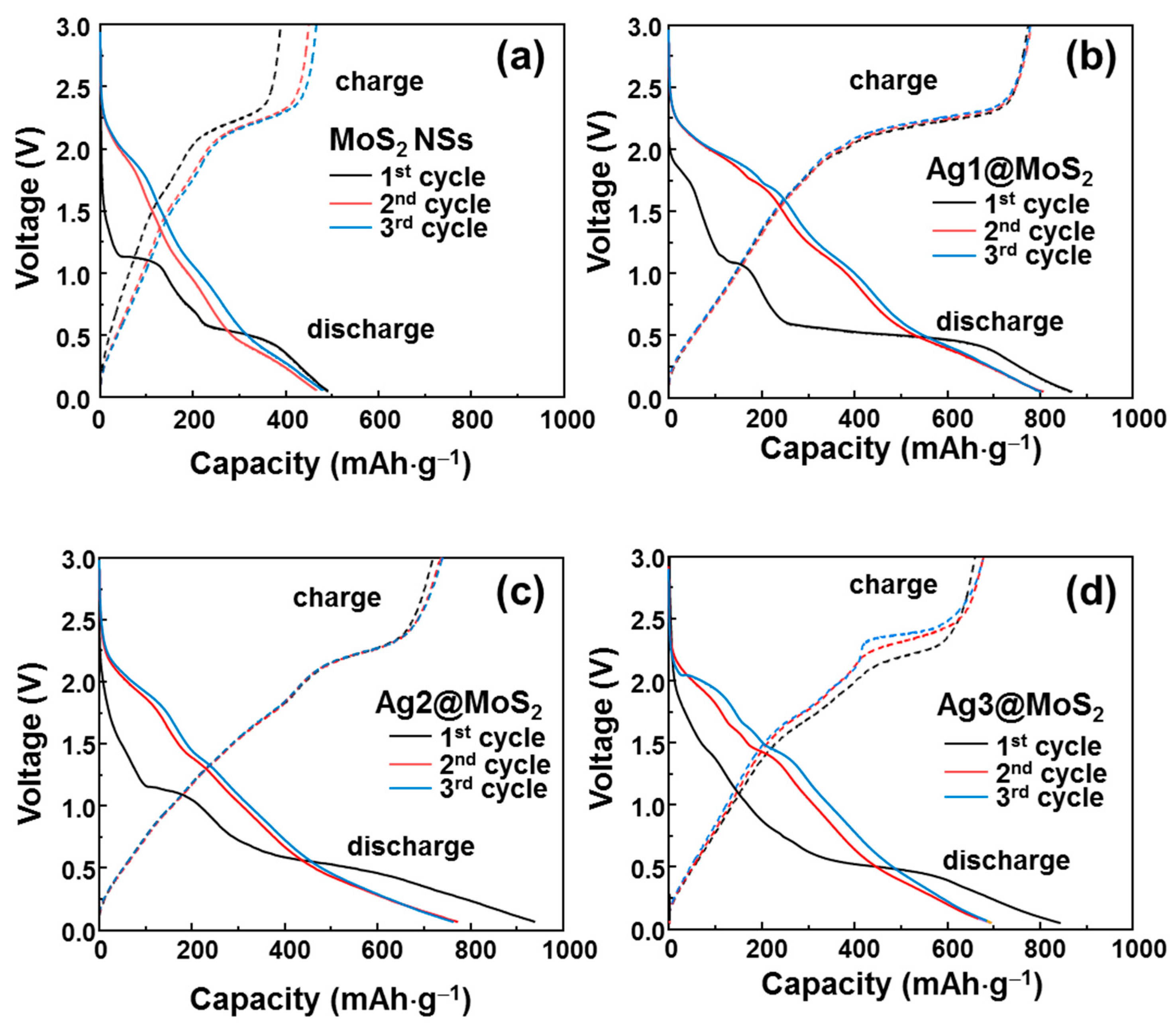
The initial voltage profiles of the as-prepared anodes are shown in Figure 5. It can be observed that with Ag decoration, the discharge/charge capacity of the MoS2 anodes is improved from ~500 to ~900 mAh·g−1, while the MoS2 NS reveals a low initial discharge/charge capacity of only ~490/466 mAh·g−1. Notably, the capacity does not decrease significantly during the initial cycles. The Ag1@MoS2 demonstrates a high initial discharge/charge capacity of 866/780 mAh·g−1 and ~800/773 mAh·g−1 at the 2nd and 3rd cycles, which is >92% of that of the first cycle. The Ag2@MoS2 anode exhibits a high discharge/charge capacity of 937/720 mAh·g−1 at the 1st cycle and ~773/739 mAh·g−1 at the 2nd and 3rd cycles. The enhancement of the lithium storage capacity could be owing to the Ag decoration improving the conductivity of the materials, thus, facilitating the lithiation/delithiation process. For the Ag3@MoS2 anode, the discharge/charge capacity is slightly reduced to ~840/660 at the 1st cycle and 694/679 mAh·g−1 at the 2nd and 3rd cycles, which can be attributed to the higher amount of Ag NPs, leading to stable cyclic performance. Meanwhile, the initial voltage profile of the MoS2 anode shows a sloping plateau at ~1.8 V, which is ascribed to the insertion of Li ions into MoS2, according to Equation (2) [26]. A sloping plateau at ~1.2 V corresponds to the reaction of lithium with sulfur in Equation (4). At below 0.5 V, the sloping plateau is related to the deep conversion reaction of lithium with MoS2 and formation of the SEI layer. The MoS2 NSs, Ag1@MoS2, and Ag2@MoS2 have similar reaction potentials. In contrast, the Ag3@MoS2 electrode has a higher plateau voltage at 2 V. The charging process of the Ag3@MoS2 anode also shows a higher plateau at ~2.4 V, higher than the plateau at ~2.2 V for the other electrodes. This process is because of a shift in the redox potential, which was indicated by the CV profiles of these anodes.
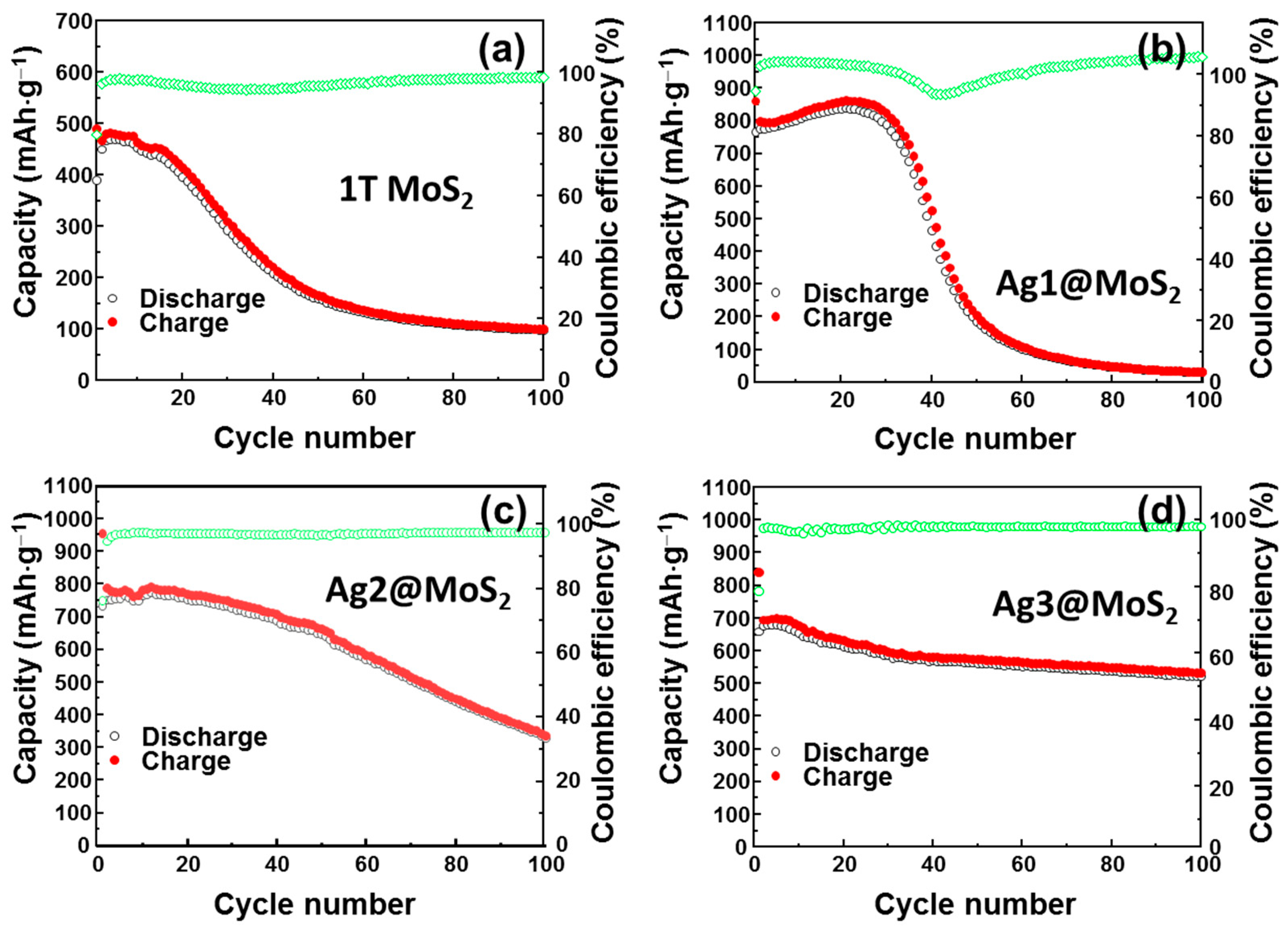
To further investigate the long-term cyclability, the performance of these anodes was analyzed in half-cells for 100 charge-discharge cycles at a current rate of 100 mA·g−1, as shown in Figure 6a–d. The MoS2 NS anode exhibits a stable cycling performance during the initial 15 cycles; however, the capacity gradually decays thereafter and remarkably fades from the 30th cycle to the 100th cycle to a capacity of ~100 mAh·g−1. This can be attributed to the formation of a broken MoS2 structure after the cycling process and a restacking of the MoS2 NS layers. By addition of a small amount of Ag nanoparticles, the Ag1@MoS2 anode improves the electrochemical performance for the initial 30 cycles; however, a dramatic capacity decay still occurs after that. A small amount of Ag enhances the conductivity of MoS2; however, the applied amount in the Ag1@MoS2 anode does not appear to be enough to protect the entire MoS2 structure. Thus, after 40 cycles, the MoS2 NS structure collapses, and the lithium storage capability worsens. A further increase in the amount of Ag diminishes the collapse of the MoS2 structure, leading to an enhancement in the cycling performance of the anode. The Ag2@MoS2 anode retains a capacity of 330 mAh·g−1 up to 100 cycles. The Ag3@MoS2 anode exhibits the best cycling performance; it retains a specific capacity of ~510 mAh·g−1 after 100 cycles, corresponding to a capacity retention of ~73%.
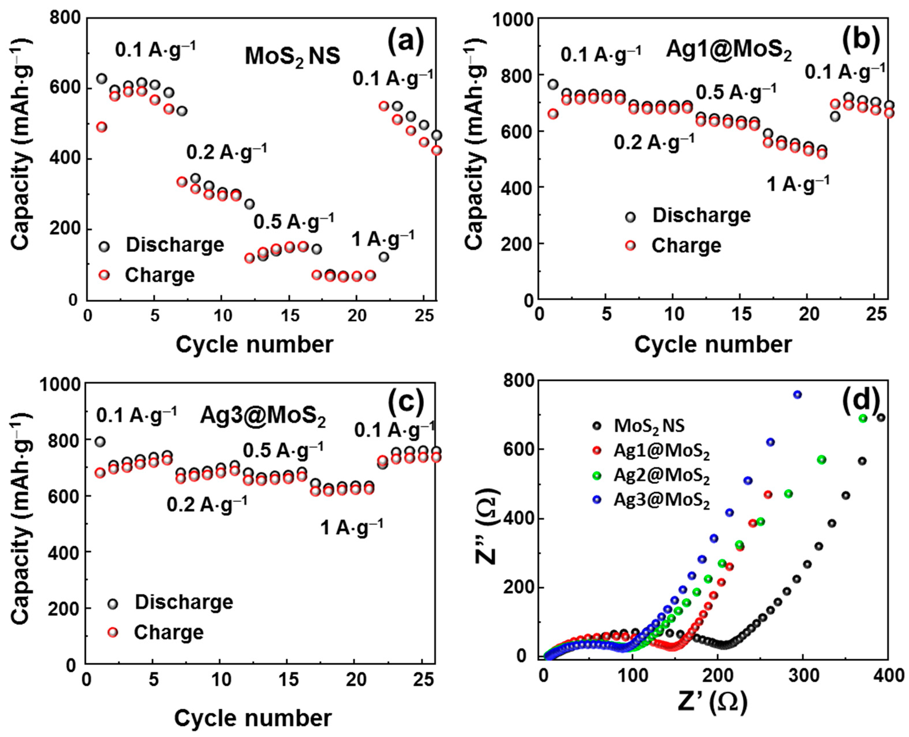
The discharge/charge rate performance of MoS2 NS without and with Ag nanoparticle decoration is shown in Figure 7a–c. These cycles were recorded at 0.1, 0.2, 0.5, and 1.0 A·g−1. As observed, bare MoS2 NSs show an inferior rate performance with a dramatic decrease in capacity from ~600 to 300, 180, and ~100 mAh·g−1, which corresponds to capacity retentions of 50, 30, and 17%, respectively. The restored capacity when going back from 1 to 0.1 A·g−1 is ~430 mAh·g−1, which is approximately 72%. When Ag nanoparticles are introduced, however, the rate performance of the anodes significantly improves. The Ag1@MoS2 anode shows capacity reductions from ~730 to 690, 650, and 550 mAh·g−1, respectively, which correspond to capacity retentions of 94, 89, and 75%, respectively. The restored capacity reaches ~676 mAh·g−1 (~92% of the initial capacity). Moreover, the Ag3@MoS2 electrode demonstrates the best rate performance, exhibiting capacity retentions of 98%, 96%, and 92%, which correspond to capacity values from 700 to 690, 677, and 646 mAh·g−1, respectively. The capacity after the high-rate test at 1 A·g−1 was 100% recovered when returning to 0.1 A·g−1. To further investigate the effect of Ag in MoS2, EIS measurements were performed to evaluate the change in the charge-transfer resistance, as illustrated in Figure 7d. The equivalent circuit using the modified Randles model contains a series resistance, SEI resistance, charge-transfer resistance, and a Warburg impedance element, and this was used to simulate the Nyquist plot [40]. The extracted charge-transfer resistances of the MoS2 NS and Ag1/2/3@MoS2 anodes are 210.5, 152.3, 99.1, and 95.8 Ω, respectively. The presence of Ag NPs clearly leads to an improvement in the anode conductivity [41,42]. Between the Ag2@MoS2 and the Ag3@MoS2 anode, the charge-transfer resistance is not significantly reduced, which indicates that the amount of Ag NPs is sufficient to decorate and enhance the electronic properties of the MoS2 NSs. Thus, the 1:10 weight ratio of AgNO3:MoS2 can contribute to the best performance in lithium-ion storage of MoS2 anode materials.
Recent works are summarized in Table 1. The reversible capacity of modified MoS2 NSs can deliver up to ~1000 mAh·g−1. From our method, the MoS2 bulk was exfoliated into few layer MoS2, with decoration of Ag on MoS2 NSs. The Ag decorated MoS2 NSs exhibited stable cyclability and high-rate performance. Moreover, the butyllithium assisted technique and uniform decorating technique for metal-particles can be easily scaled up to industrial purpose. This work can be further improved by optimizing and modifying the synthesis of MoS2 to develop uniform MoS2 single layer with the insertion of butyllithium by applying the pressure or temperature.
4. Conclusions
In this study, we successfully prepared MoS2 NS with Ag NP decoration, using the assistance of MPA functionalization. The structure and morphology of the Ag NPs on the MoS2 NSs were confirmed by SEM, XRD, and TEM measurements. The size of the MoS2 NSs was from 100 nm to ~3 μm. Ag NPs with a size of a few nm were decorated on the surface of the MoS2 NSs. The MoS2 NS shows inferior cycling performance of lithium storage capacity (~500 mAh·g−1) and rate performance. By incorporating Ag NPs, the storage capacity and rate performance of anodes were significantly improved. Among the three anodes prepared, the Ag3@MoS2 anode demonstrated the best cycling performance retention capacity of 73% compared to that in the first cycle after 100 cycles. Moreover, this anode could restore ~100% of the capacity after high rate performance. These results suggest that Ag-decorated MoS2 can be a potential anode for a high-rate and high-stability anode in lithium storage applications in the future.
Author Contributions
T.P.N.: Conceptualization, Methodology, Validation, Visualization, Writing–review & editing. I.T.K.: Project administration, Funding acquisition, Review & editing. Both authors have read and agreed to the published version of the manuscript. All authors have read and agreed to the published version of the manuscript.
Funding
This work was supported by the National Research Foundation of Korea (NRF) grant funded by the Korean government (MSIT) (NRF-2020R1F1A1048335). This research was also supported by the Basic Science Research Capacity Enhancement Project through a Korea Basic Science Institute (National Research Facilities and Equipment Center) grant funded by the Ministry of Education (2019R1A6C1010016).
Institutional Review Board Statement
Not applicable.
Informed Consent Statement
Not applicable.
Data Availability Statement
Data is contained within the article.
Conflicts of Interest
The authors declare no conflict of interest.
References
- Song, X.F.; Hu, J.L.; Zeng, H.B. Two-dimensional semiconductors: Recent progress and future perspectives. J. Mater. Chem. C 2013, 1, 2952–2969. [Google Scholar] [CrossRef]
- Nguyen, T.P.; Sohn, W.; Oh, J.H.; Jang, H.W.; Kim, S.Y. Size-Dependent Properties of Two-Dimensional MoS2 and WS2. J. Phys. Chem. C 2016, 120, 10078–10085. [Google Scholar] [CrossRef]
- Li, H.; Lu, G.; Yin, Z.; He, Q.; Li, H.; Zhang, Q.; Zhang, H. Optical Identification of Single- and Few-Layer MoS2 Sheets. Small 2012, 8, 682–686. [Google Scholar] [CrossRef] [PubMed]
- Joensen, P.; Frindt, R.F.; Morrison, S.R. Single-layer MoS2. Mater. Res. Bull. 1986, 21, 457–461. [Google Scholar] [CrossRef]
- Radisavljevic, B.; Radenovic, A.; Brivio, J.; Giacometti, V.; Kis, A. Single-layer MoS2 transistors. Nat. Nanotechnol. 2011, 6, 147–150. [Google Scholar] [CrossRef]
- Li, S.; Chen, Z.; Zhang, W. Dye-sensitized solar cells based on WS2 counter electrodes. Mater. Lett. 2012, 72, 22–24. [Google Scholar] [CrossRef]
- Kim, C.; Nguyen, T.P.; Le, Q.V.; Jeon, J.M.; Jang, H.W.; Kim, S.Y. Performances of Liquid-Exfoliated Transition Metal Dichalcogenides as Hole Injection Layers in Organic Light-Emitting Diodes. Adv. Funct. Mater. 2015, 25, 4512–4519. [Google Scholar] [CrossRef]
- Nguyen, T.P.; Le, Q.V.; Choi, S.; Lee, T.H.; Hong, S.-P.; Choi, K.S.; Jang, H.W.; Lee, M.H.; Park, T.J.; Kim, S.Y. Surface extension of MeS2 (Me=Mo or W) nanosheets by embedding MeSx for hydrogen evolution reaction. Electrochim. Acta 2018, 292, 136–141. [Google Scholar] [CrossRef]
- He, Q.; Wang, L.; Yin, K.; Luo, S. Vertically Aligned Ultrathin 1T-WS2 Nanosheets Enhanced the Electrocatalytic Hydrogen Evolution. Nanoscale Res. Lett. 2018, 13, 167. [Google Scholar] [CrossRef]
- Voiry, D.; Salehi, M.; Silva, R.; Fujita, T.; Chen, M.; Asefa, T.; Shenoy, V.B.; Eda, G.; Chhowalla, M. Conducting MoS2 nanosheets as catalysts for hydrogen evolution reaction. Nano Lett. 2013, 13, 6222–6227. [Google Scholar] [CrossRef]
- Nguyen, Q.H.; Hur, J. MoS2-C-TiC Nanocomposites as New Anode Materials for High-Performance Lithium-Ion Batteries. J. Nanosci. Nanotechnol. 2019, 19, 996–1000. [Google Scholar] [CrossRef] [PubMed]
- Nguyen, T.P.; Kim, I.T. W2C/WS2 Alloy Nanoflowers as Anode Materials for Lithium-Ion Storage. Nanomaterials (Basel) 2020, 10, 1336. [Google Scholar] [CrossRef] [PubMed]
- El Beqqali, O.; Zorkani, I.; Rogemond, F.; Chermette, H.; Chaabane, R.B.; Gamoudi, M.; Guillaud, G. Electrical properties of molybdenum disulfide MoS2. Experimental study and density functional calculation results. Synth. Met. 1997, 90, 165–172. [Google Scholar] [CrossRef]
- Molina-Sanchez, A.; Wirtz, L. Phonons in single-layer and few-layer MoS2 and WS2. Phys. Rev. B 2011, 84, 155413. [Google Scholar] [CrossRef] [Green Version]
- Castellanos-Gomez, A.; Poot, M.; Steele, G.A.; Van Der Zant, H.S.J.; Agrait, N.; Rubio-Bollinger, G. Elastic properties of freely suspended MoS2 nanosheets. Adv. Mater. 2012, 24, 24. [Google Scholar] [CrossRef] [PubMed] [Green Version]
- Gao, D.; Si, M.; Li, J.; Zhang, J.; Zhang, Z.; Yang, Z.; Xue, D. Ferromagnetism in freestanding MoS2 nanosheets. Nanoscale. Res. Lett. 2013, 8, 129–136. [Google Scholar] [CrossRef] [Green Version]
- Nguyen, T.P.; Kim, I.T. Self-Assembled Few-Layered MoS2 on SnO2 Anode for Enhancing Lithium-Ion Storage. Nanomaterials 2020, 10, 2558. [Google Scholar] [CrossRef]
- Stephenson, T.; Li, Z.; Olsen, B.; Mitlin, D. Lithium ion battery applications of molybdenum disulfide (MoS2) nanocomposites. Energy Environ. Sci. 2014, 7, 209–231. [Google Scholar] [CrossRef]
- Cha, E.; Patel, M.D.; Park, J.; Hwang, J.; Prasad, V.; Cho, K.; Choi, W. 2D MoS2 as an efficient protective layer for lithium metal anodes in high-performance Li–S batteries. Nat. Nanotechnol. 2018, 13, 337–344. [Google Scholar] [CrossRef]
- Bai, J.; Zhao, B.; Zhou, J.; Si, J.; Fang, Z.; Li, K.; Ma, H.; Dai, J.; Zhu, X.; Sun, Y. Glucose-Induced Synthesis of 1T-MoS2/C Hybrid for High-Rate Lithium-Ion Batteries. Small 2019, 15, 1805420. [Google Scholar] [CrossRef]
- Chen, Y.; Lu, J.; Wen, S.; Lu, L.; Xue, J. Synthesis of SnO2/MoS2 composites with different component ratios and their applications as lithium ion battery anodes. J. Mater. Chem. A 2014, 2, 17857–17866. [Google Scholar] [CrossRef]
- Tripathi, K.M.; Ahn, H.T.; Chung, M.; Le, X.A.; Saini, D.; Bhati, A.; Sonkar, S.K.; Kim, M.I.; Kim, T. N, S, and P-Co-doped Carbon Quantum Dots: Intrinsic Peroxidase Activity in a Wide pH Range and Its Antibacterial Applications. ACS Biomater. Sci. Eng. 2020, 6, 5527–5537. [Google Scholar] [CrossRef]
- Zhu, X.; Yang, C.; Xiao, F.; Wang, J.; Su, X. Synthesis of nano-TiO2-decorated MoS2 nanosheets for lithium ion batteries. New J. Chem. 2015, 39, 683–688. [Google Scholar] [CrossRef]
- Pan, L.; Liu, Y.T.; Xie, X.M.; Zhu, X.D. Coordination-driven hierarchical assembly of silver nanoparticles on MoS2 nanosheets for improved lithium storage. Chem. Asian J. 2014, 9, 1519–1524. [Google Scholar] [CrossRef] [PubMed]
- Li, Y.; Chang, K.; Sun, Z.; Shangguan, E.; Tang, H.; Li, B.; Sun, J.; Chang, Z. Selective Preparation of 1T- and 2H-Phase MoS2 Nanosheets with Abundant Monolayer Structure and Their Applications in Energy Storage Devices. ACS Appl. Energy Mater. 2020, 3, 998–1009. [Google Scholar] [CrossRef]
- Wang, G.; Zhang, J.; Yang, S.; Wang, F.; Zhuang, X.; Müllen, K.; Feng, X. Vertically Aligned MoS2 Nanosheets Patterned on Electrochemically Exfoliated Graphene for High-Performance Lithium and Sodium Storage. Adv. Energy Mater. 2018, 8, 1702254. [Google Scholar] [CrossRef] [Green Version]
- Tang, W.-j.; Wang, X.-l.; Xie, D.; Xia, X.-h.; Gu, C.-d.; Tu, J.-p. Hollow metallic 1T MoS2 arrays grown on carbon cloth: A freestanding electrode for sodium ion batteries. J. Mater. Chem. A 2018, 6, 18318–18324. [Google Scholar] [CrossRef]
- Li, Z.; Sun, P.; Zhan, X.; Zheng, Q.; Feng, T.; Braun, P.V.; Qi, S. Metallic 1T phase MoS2/MnO composites with improved cyclability for lithium-ion battery anodes. J. Alloys Compd. 2019, 796, 25–32. [Google Scholar] [CrossRef]
- Presolski, S.; Pumera, M. Covalent functionalization of MoS2. Mater. Today 2016, 19, 140–145. [Google Scholar] [CrossRef]
- Zhou, L.; He, B.; Yang, Y.; He, Y. Facile approach to surface functionalized MoS2 nanosheets. RSC Adv. 2014, 4, 32570–32578. [Google Scholar] [CrossRef]
- Dines, M.B. Lithium intercalation via -Butyllithium of the layered transition metal dichalcogenides. Mater. Res. Bull. 1975, 10, 287–291. [Google Scholar] [CrossRef]
- Eda, G.; Yamaguchi, H.; Voiry, D.; Fujita, T.; Chen, M.; Chhowalla, M. Photoluminescence from Chemically Exfoliated MoS2. Nano Lett. 2011, 11, 5111–5116. [Google Scholar] [CrossRef] [PubMed]
- Lei, Z.; Zhan, J.; Tang, L.; Zhang, Y.; Wang, Y. Recent Development of Metallic (1T) Phase of Molybdenum Disulfide for Energy Conversion and Storage. Adv. Energy Mater 2018, 8, 1703482. [Google Scholar] [CrossRef]
- Takahashi, Y.; Nakayasu, Y.; Iwase, K.; Kobayashi, H.; Honma, I. Supercritical hydrothermal synthesis of MoS2 nanosheets with controllable layer number and phase structure. Dalton Trans. 2020, 49, 9377–9384. [Google Scholar] [CrossRef]
- Li, F.; Li, J.; Cao, Z.; Lin, X.; Li, X.; Fang, Y.; An, X.; Fu, Y.; Jin, J.; Li, R. MoS2 quantum dot decorated RGO: A designed electrocatalyst with high active site density for the hydrogen evolution reaction. J. Mater. Chem. A 2015, 3, 21772–21778. [Google Scholar] [CrossRef]
- Altavilla, C.; Sarno, M.; Ciambelli, P. A Novel Wet Chemistry Approach for the Synthesis of Hybrid 2D Free-Floating Single or Multilayer Nanosheets of MS2@oleylamine (M=Mo, W). Chem. Mater. 2011, 23, 3879–3885. [Google Scholar] [CrossRef]
- Zhang, X.; Ding, P.; Sun, Y.; Wang, Y.; Wu, Y.; Guo, J. Shell-core MoS2 nanosheets@Fe3O4 sphere heterostructure with exposed active edges for efficient electrocatalytic hydrogen production. J. Alloys Compd. 2017, 715, 53–59. [Google Scholar] [CrossRef]
- Taillades, G.; Sarradin, J. Silver: High performance anode for thin film lithium ion batteries. J. Power Sources 2004, 125, 199–205. [Google Scholar] [CrossRef]
- Ma, Y.; Ma, Y.; Giuli, G.; Diemant, T.; Behm, R.J.; Geiger, D.; Kaiser, U.; Ulissi, U.; Passerini, S.; Bresser, D. Conversion/alloying lithium-ion anodes—Enhancing the energy density by transition metal doping. Sustain. Energy Fuels 2018, 2, 2601–2608. [Google Scholar] [CrossRef] [Green Version]
- Vo, T.N.; Kim, D.S.; Mun, Y.S.; Lee, H.J.; Ahn, S.-k.; Kim, I.T. Fast charging sodium-ion batteries based on Te-P-C composites and insights to low-frequency limits of four common equivalent impedance circuits. Chem. Eng. J. 2020, 398, 125703. [Google Scholar] [CrossRef]
- Hasani, A.; Nguyen, T.P.; Tekalgne, M.; Van Le, Q.; Choi, K.S.; Lee, T.H.; Jung Park, T.; Jang, H.W.; Kim, S.Y. The role of metal dopants in WS2 nanoflowers in enhancing the hydrogen evolution reaction. Appl. Catal. A. 2018, 567, 73–79. [Google Scholar] [CrossRef]
- Kadam, A.N.; Bhopate, D.P.; Kondalkar, V.V.; Majhi, S.M.; Bathula, C.D.; Tran, A.-V.; Lee, S.-W. Facile synthesis of Ag-ZnO core–shell nanostructures with enhanced photocatalytic activity. J. Ind. Eng. Chem. 2018, 61, 78–86. [Google Scholar] [CrossRef]
- Lu, L.; Min, F.; Luo, Z.; Wang, S.; Teng, F.; Li, G.; Feng, C. Synthesis and electrochemical properties of tin-doped MoS2 (Sn/MoS2) composites for lithium ion battery applications. J. Nanopart. Res. 2016, 18, 357. [Google Scholar] [CrossRef]
- Zhong, Y.; Shi, T.; Huang, Y.; Cheng, S.; Chen, C.; Liao, G.; Tang, Z. Three-dimensional MoS2/Graphene Aerogel as Binder-free Electrode for Li-ion Battery. Nanoscale. Res. Lett. 2019, 14, 85. [Google Scholar] [CrossRef] [PubMed] [Green Version]
- Huang, X.; Cai, X.; Xu, D.; Chen, W.; Wang, S.; Zhou, W.; Meng, Y.; Fang, Y.; Yu, X. Hierarchical Fe2O3@CNF fabric decorated with MoS2 nanosheets as a robust anode for flexible lithium-ion batteries exhibiting ultrahigh areal capacity. J. Mater. Chem. A 2018, 6, 16890–16899. [Google Scholar] [CrossRef]
Figure 1.
(a,b) Scanning electron microscopy (SEM) images of MoS2 nanosheets (NSs); (c) illustration of Ag-decorated MoS2 NS; SEM images of (d) Ag1@MoS2, (e) Ag2@MoS2, and (f) Ag3@MoS2 NSs.
Figure 1.
(a,b) Scanning electron microscopy (SEM) images of MoS2 nanosheets (NSs); (c) illustration of Ag-decorated MoS2 NS; SEM images of (d) Ag1@MoS2, (e) Ag2@MoS2, and (f) Ag3@MoS2 NSs.

Figure 2.
X-ray diffraction patterns of bulk MoS2, LixMoS2, and Ag3@MoS2 materials.

Figure 3.
(a,b) Transmission electron microscopy (TEM) image and element mapping images of Ag3@MoS2 materials; (c,f) TEM, high-resolution TEM (HRTEM) with inset selected area electron diffraction (SAED) pattern of MoS2 NS; (d,e) TEM, HRTEM with inset SAED pattern of Ag3@MoS2 materials.
Figure 3.
(a,b) Transmission electron microscopy (TEM) image and element mapping images of Ag3@MoS2 materials; (c,f) TEM, high-resolution TEM (HRTEM) with inset selected area electron diffraction (SAED) pattern of MoS2 NS; (d,e) TEM, HRTEM with inset SAED pattern of Ag3@MoS2 materials.

Figure 4.
Cyclic voltammetry (CV) profiles of (a) MoS2 NSs, (b) Ag1@MoS2, (c) Ag2@MoS2 and (d) Ag3@MoS2 anodes, over the initial three cycles.
Figure 4.
Cyclic voltammetry (CV) profiles of (a) MoS2 NSs, (b) Ag1@MoS2, (c) Ag2@MoS2 and (d) Ag3@MoS2 anodes, over the initial three cycles.

Figure 5.
Initial voltage profiles of (a) MoS2 NSs, (b) Ag1@MoS2, (c) Ag2@MoS2, and (d) Ag3@MoS2 anodes.
Figure 5.
Initial voltage profiles of (a) MoS2 NSs, (b) Ag1@MoS2, (c) Ag2@MoS2, and (d) Ag3@MoS2 anodes.

Figure 6.
Cyclic performance of (a) MoS2 NSs, (b) Ag1@MoS2, (c) Ag2@MoS2, and (d) Ag3@MoS2 anodes.

Figure 7.
Rate performance of (a) MoS2 NSs, (b) Ag1@MoS2, (c) Ag3@MoS2, and (d) Nyquist plots of MoS2 without/with Ag-decorated anodes.
Figure 7.
Rate performance of (a) MoS2 NSs, (b) Ag1@MoS2, (c) Ag3@MoS2, and (d) Nyquist plots of MoS2 without/with Ag-decorated anodes.


Table 1.
Recent research of MoS2 nanosheets (NSs) for Li-ion storage.
| Materials | Method | Phase of MoS2 | Reversible Capacity after 100 Cycles at 0.1 A·g−1 (mAh·g−1) | Reference |
|---|---|---|---|---|
| Ag/MoS2 nanohybrids | Sonication | 2H | ~920 (after 50 cycles) | [24] |
| Sn/MoS2 composite | Hydrothermal | - | ~1087 | [43] |
| MoS2/reduced graphene oxide | Hydrothermal | - | ~667 | [44] |
| TiO2 decorated MoS2 | Hydrothermal | 2H | ~604 | [23] |
| Fe2O3@Carbon nanofiber/MoS2 | Electrospinning and hydrothermal | 2H | ~900 (at 0.2 Ah·g−1) | [45] |
| 1T MoS2 | Liquid exfoliation assisted lithium molten salt at 1050 °C | 1T | ~855 | [25] |
| Ag nanoparticles-decorated MoS2 NSs | Liquid exfoliation method | 1T | ~510 | [This work] |
Publisher’s Note: MDPI stays neutral with regard to jurisdictional claims in published maps and institutional affiliations. |
© 2021 by the authors. Licensee MDPI, Basel, Switzerland. This article is an open access article distributed under the terms and conditions of the Creative Commons Attribution (CC BY) license (http://creativecommons.org/licenses/by/4.0/).
Share and Cite
MDPI and ACS Style
Nguyen, T.P.; Kim, I.T. Ag Nanoparticle-Decorated MoS2 Nanosheets for Enhancing Electrochemical Performance in Lithium Storage. Nanomaterials 2021, 11, 626. https://0-doi-org.brum.beds.ac.uk/10.3390/nano11030626
AMA Style
Nguyen TP, Kim IT. Ag Nanoparticle-Decorated MoS2 Nanosheets for Enhancing Electrochemical Performance in Lithium Storage. Nanomaterials. 2021; 11(3):626. https://0-doi-org.brum.beds.ac.uk/10.3390/nano11030626
Chicago/Turabian StyleNguyen, Thang Phan, and Il Tae Kim. 2021. "Ag Nanoparticle-Decorated MoS2 Nanosheets for Enhancing Electrochemical Performance in Lithium Storage" Nanomaterials 11, no. 3: 626. https://0-doi-org.brum.beds.ac.uk/10.3390/nano11030626
Note that from the first issue of 2016, this journal uses article numbers instead of page numbers. See further details here.