
Efficient Removal of Cr(VI) by TiO2 Based Micro-Nano Reactor via the Synergy of Adsorption and Photocatalysis

Abstract
:1. Introduction
2. Materials and Methods
2.1. Reagents and Materials
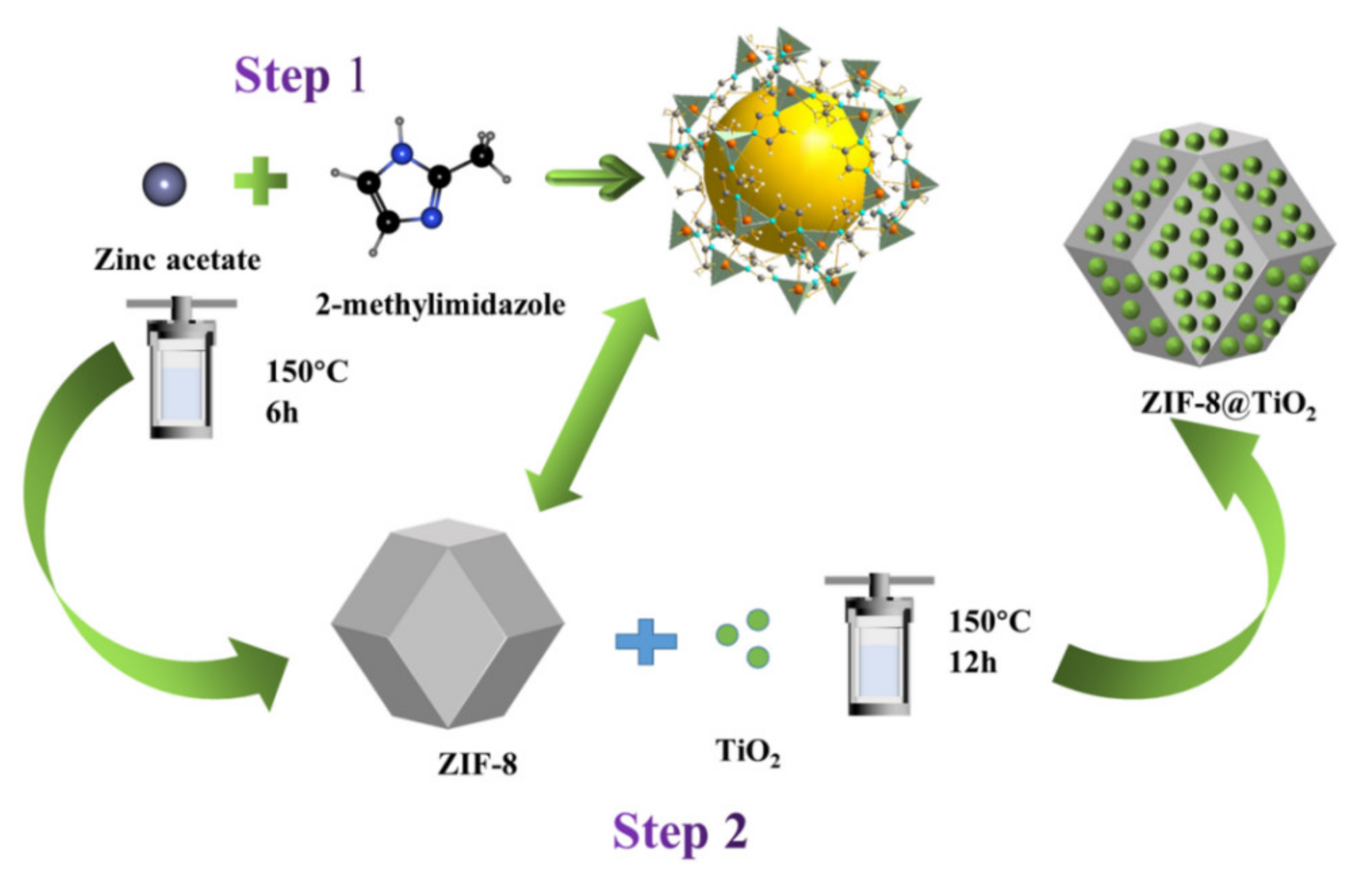
2.2. Synthesis of ZIF-8
2.3. Synthesis of ZIF-8@TiO2
2.4. Cr(VI) Removal Measurement
2.5. Photoelectrochemical Measurement
2.6. Characterization
3. Results
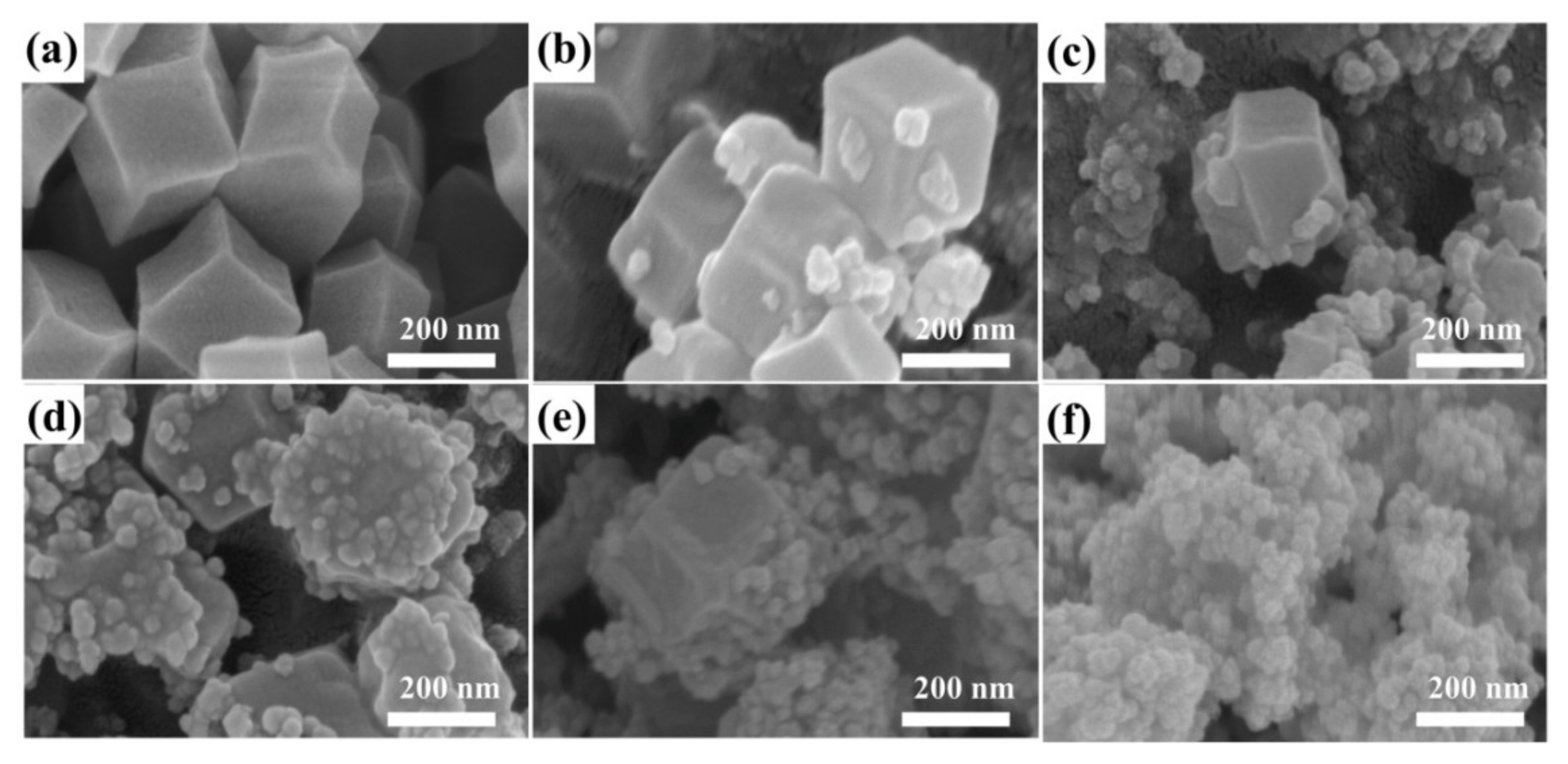
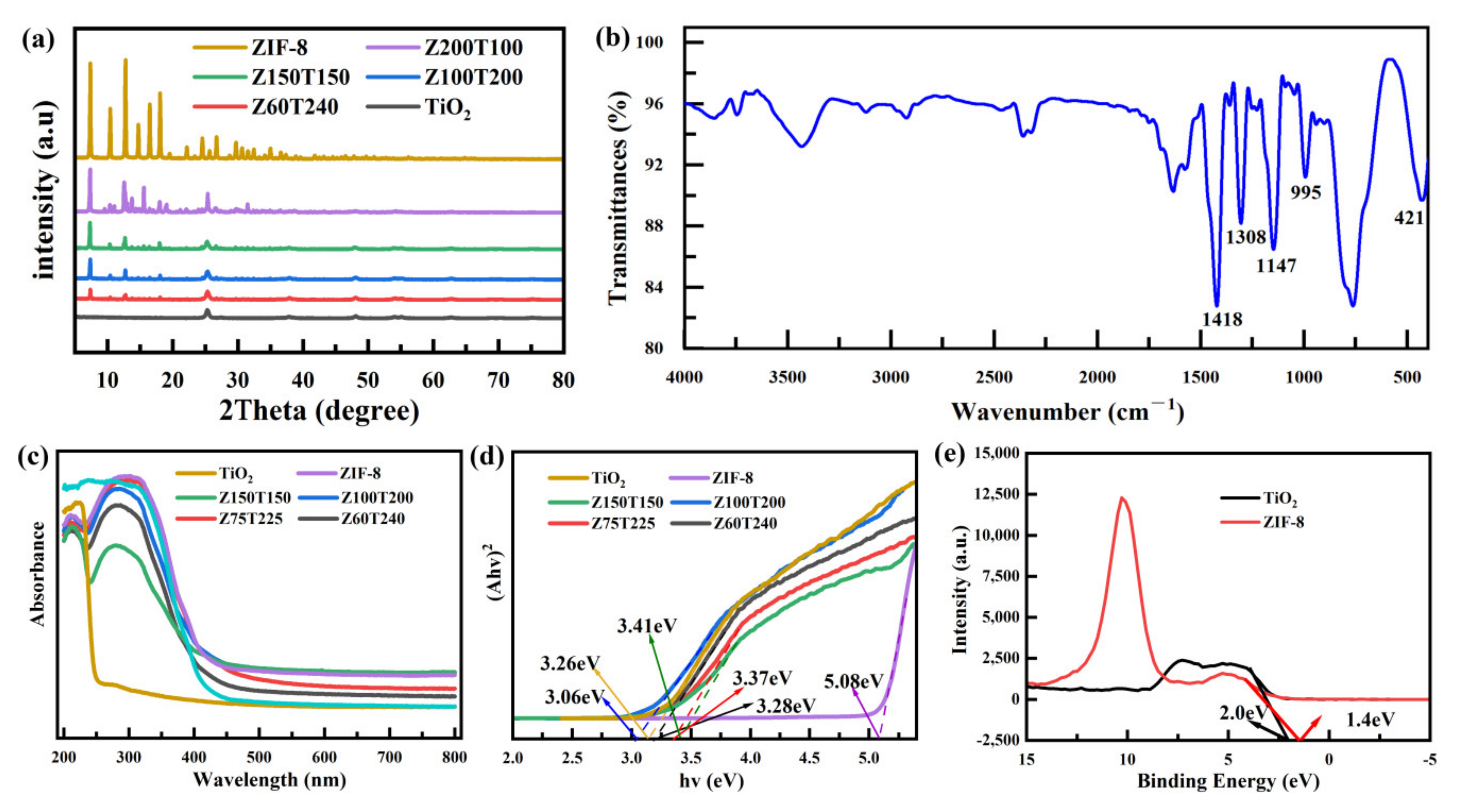
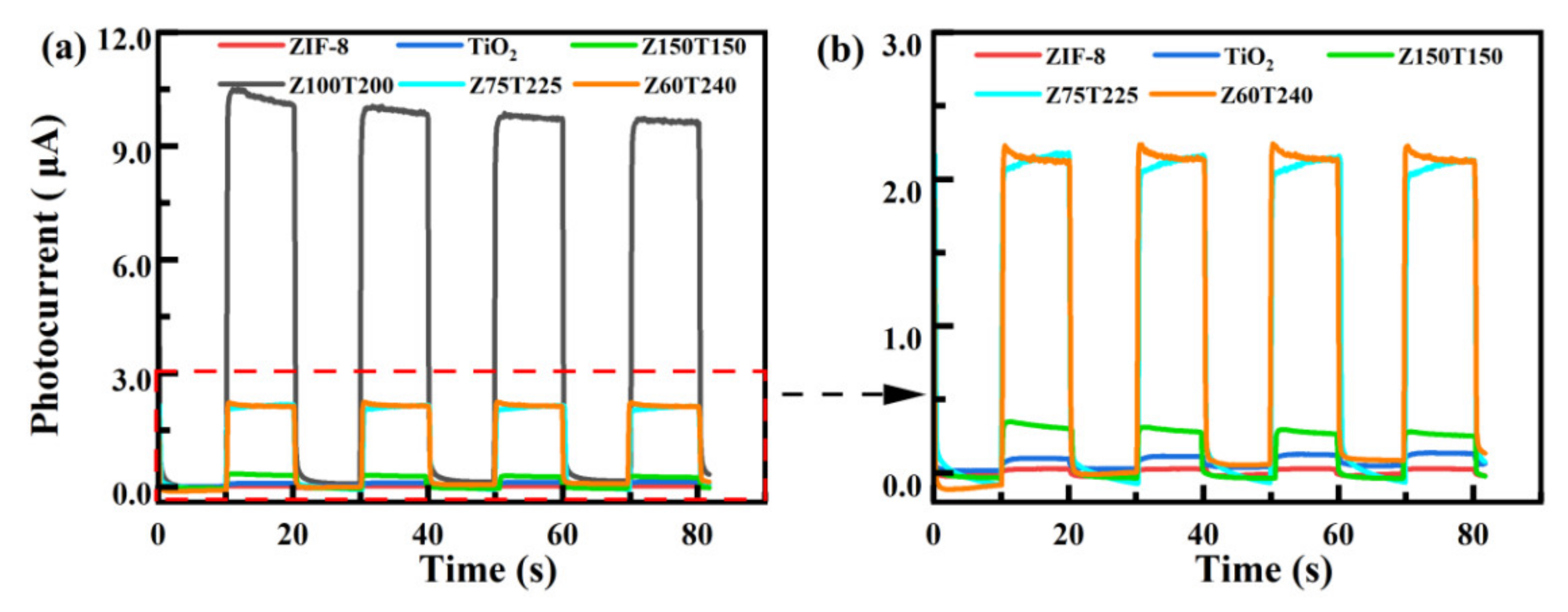
3.1. Microstructure, Composition, and Performance Characterization of ZxTy
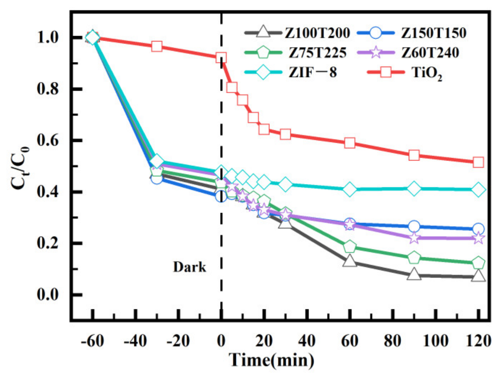
3.2. Removal of Cr (VI)
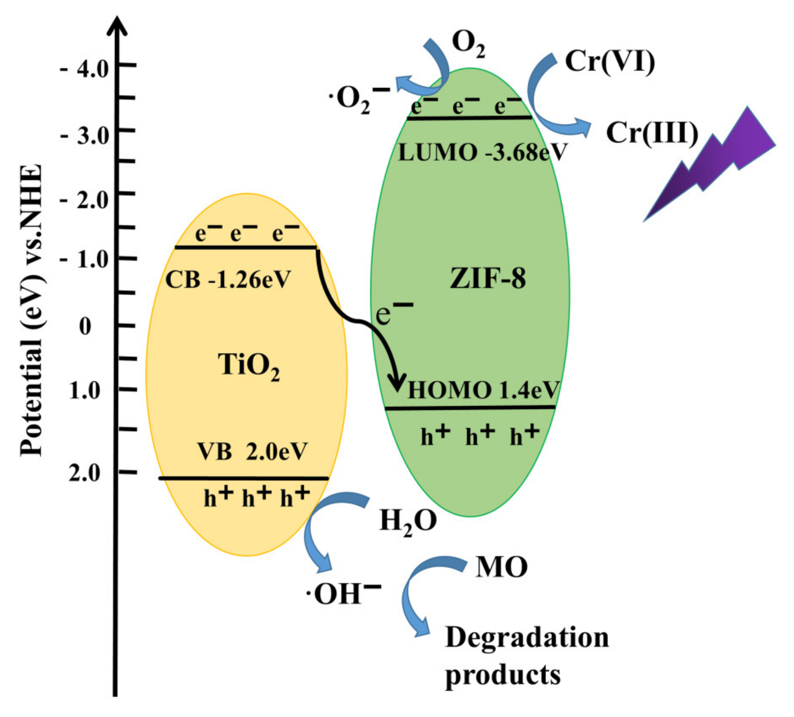
3.3. Possible Mechanism of Photocatalytic Activity
4. Conclusions
Supplementary Materials
Author Contributions
Funding
Institutional Review Board Statement
Informed Consent Statement
Data Availability Statement
Conflicts of Interest
References
- Zhang, X.; Zhang, Y.; Shi, P.; Bi, Z.; Shan, Z.; Ren, L. The deep challenge of nitrate pollution in river water of China. Sci. Total Environ. 2021, 770, 144674. [Google Scholar] [CrossRef] [PubMed]
- Yanagida, S.; Yajima, T.; Takei, T.; Kumada, N. Removal of hexavalent chromium from water by Z-scheme photocatalysis using TiO2 (rutile) nanorods loaded with Au core–Cu2O shell particles. J. Environ. Sci. 2022, 115, 173–189. [Google Scholar] [CrossRef]
- Kim, T.-Y.; Song, D.; Barea, E.M.; Lee, J.H.; Kim, Y.R.; Cho, W.; Lee, S.; Rahman, M.M.; Bisquert, J.; Kang, Y.S. Origin of high open-circuit voltage in solid state dye-sensitized solar cells employing polymer electrolyte. Nano Energy 2016, 28, 455–461. [Google Scholar] [CrossRef]
- Shan, Y.; Cui, J.; Liu, Y.; Zhao, W. TiO2 anchored on MoS2 nanosheets based on molybdenite exfoliation as an efficient cathode for enhanced Cr (VI) reduction in microbial fuel cell. Environ. Res. 2020, 190, 110010. [Google Scholar] [CrossRef] [PubMed]
- Cao, R.; Liu, S.; Yang, X.; Wang, C.; Wang, Y.; Wang, W.; Pi, Y. Enhanced remediation of Cr(VI)-contaminated groundwater by coupling electrokinetics with ZVI/Fe3O4/AC-based permeable reactive barrier. J. Environ. Sci. 2022, 112, 280–290. [Google Scholar] [CrossRef]
- Hasnat, M.A.; Safwan, J.A.; Islam, M.S.; Rahman, Z.; Karim, M.R.; Pirzada, T.J.; Samed, A.J.; Rahman, M.M. Electrochemical decolorization of Methylene blue at Pt electrode in KCl solution for environmental remediation. J. Ind. Eng. Chem. 2015, 21, 787–791. [Google Scholar] [CrossRef]
- Chen, W.; Zhang, Z.; Yang, C.; Liu, J.; Shen, H.; Yang, K.; Wang, Z. PIM-based mixed-matrix membranes containing MOF-801/ionic liquid nanocomposites for enhanced CO2 separation performance. J. Membr. Sci. 2021, 636, 119581. [Google Scholar] [CrossRef]
- Li, L.L.; Feng, X.Q.; Han, R.P.; Zang, S.Q.; Yang, G. Cr(VI) removal via anion exchange on a silver-triazolate MOF. J. Hazard. Mater. 2017, 321, 622–628. [Google Scholar] [CrossRef] [PubMed]
- Fu, H.R.; Wang, N.; Qin, J.H.; Han, M.L.; Ma, L.F.; Wang, F. Spatial confinement of a cationic MOF: A SC-SC approach for high capacity Cr(vi)-oxyanion capture in aqueous solution. Chem. Commun. 2018, 54, 11645–11648. [Google Scholar] [CrossRef]
- Daradmare, S.; Xia, M.; Le, V.N.; Kim, J.; Park, B.J. Metal-organic frameworks/alginate composite beads as effective adsorbents for the removal of hexavalent chromium from aqueous solution. Chemosphere 2021, 270, 129487. [Google Scholar] [CrossRef] [PubMed]
- Chen, Z.; Li, Y.; Guo, M.; Xu, F.; Wang, P.; Du, Y.; Na, P. One-pot synthesis of Mn-doped TiO2 grown on graphene and the mechanism for removal of Cr(VI) and Cr(III). J. Hazard. Mater. 2016, 310, 188–198. [Google Scholar] [CrossRef]
- Rahman, M.M.; Asiri, A.M.; Youssef, T.E.; Marwani, H.M. Photocatalytic degradation of remazol brilliant orange 3R using wet-chemically prepared CdO-ZnO nanofibers for environmental remediation. Mater. Express 2016, 6, 137–148. [Google Scholar] [CrossRef]
- Asiri, A.M.; Khan, S.B.; Alamry, K.A.; Marwani, H.M.; Rahman, M.M. Growth of Mn3O4 on cellulose matrix: Nanohybrid as a solid phase adsorbent for trivalent chromium. Appl. Surf. Sci. 2013, 270, 539–544. [Google Scholar] [CrossRef]
- Hussain, M.M.; Asiri, A.M.; Arshad, M.N.; Rahman, M.M. Synthesis, characterization, and crystal structure of (E)-N′-(4-Bromobenzylidene)-benzenesulfonohydrazide and its application as a sensor of chromium ion detection from environmental samples. J. Mol. Struct. 2020, 1207, 127810. [Google Scholar] [CrossRef]
- El-Shishtawy, R.M.; Rahman, M.M.; Ali Sheikh, T.; Nadeem Arshad, M.; Al-Zahrani, F.A.M.; Asiri, A.M. A New Cr3+ Electrochemical Sensor Based on ATNA/Nafion/Glassy Carbon Electrode. Materials 2020, 13, 2695. [Google Scholar] [CrossRef] [PubMed]
- Hossain, M.A.; Elias, M.; Sarker, D.R.; Diba, Z.R.; Mithun, J.M.; Azad, M.A.K.; Siddiquey, I.A.; Rahman, M.M.; Uddin, J.; Uddin, M.N. Synthesis of Fe- or Ag-doped TiO2–MWCNT nanocomposite thin films and their visible-light-induced catalysis of dye degradation and antibacterial activity. Res. Chem. Intermediat. 2018, 44, 2667–2683. [Google Scholar] [CrossRef]
- Zhang, Y.; Xu, M.; Li, H.; Ge, H.; Bian, Z. The enhanced photoreduction of Cr(VI) to Cr(III) using carbon dots coupled TiO2 mesocrystals. Appl. Catal. B Environ. 2018, 226, 213–219. [Google Scholar] [CrossRef]
- Shahmohammadi, M.; Nagay, B.E.; Barão, V.A.R.; Sukotjo, C.; Jursich, G.; Takoudis, C.G. Atomic layer deposition of TiO2, ZrO2 and TiO2/ZrO2 mixed oxide nanofilms on PMMA for enhanced biomaterial functionalization. Appl. Surf. Sci. 2022, 578, 151891. [Google Scholar] [CrossRef]
- Sun, T.; Song, J.; Liu, Z.; Jiang, W. The transport and retention of CQDs-doped TiO2 in packed columns and 3D printed micromodels. J. Environ. Sci. 2022, 113, 365–375. [Google Scholar] [CrossRef]
- Sathishkumar, K.; Li, Y.; Alsalhi, M.S.; Muthukumar, B.; Gaurav, G.K.; Devanesan, S.; Rajasekar, A.; Manikandan, R. Enhanced biological nitrate removal by gC3N4/TiO2 composite and role of extracellular polymeric substances. Environ. Res. 2021, 112158. [Google Scholar] [CrossRef]
- Lyulyukin, M.; Filippov, T.; Cherepanova, S.; Solovyeva, M.; Prosvirin, I.; Bukhtiyarov, A.; Kozlov, D.; Selishchev, D. Synthesis, Characterization and Visible-Light Photocatalytic Activity of Solid and TiO2-Supported Uranium Oxycompounds. Nanomaterials 2021, 11, 1036. [Google Scholar] [CrossRef] [PubMed]
- Liu, Y.; Deng, Y.; Sun, Z.; Wei, J.; Zheng, G.; Asiri, A.M.; Khan, S.B.; Rahman, M.M.; Zhao, D. Hierarchical Cu2S microsponges constructed from nanosheets for efficient photocatalysis. Small 2013, 9, 2702–2708. [Google Scholar] [CrossRef]
- Subhan, M.A.; Rifat, T.P.; Chandra Saha, P.; Alam, M.M.; Asiri, A.M.; Rahman, M.M.; Akter, S.; Raihan, T.; Azad, A.K.; Uddin, J. Enhanced visible light-mediated photocatalysis, antibacterial functions and fabrication of a 3-chlorophenol sensor based on ternary Ag2O·SrO·CaO. RSC. Adv. 2020, 10, 11274–11291. [Google Scholar] [CrossRef] [Green Version]
- Zhao, Y.; Chang, W.; Huang, Z.; Feng, X.; Ma, L.; Qi, X.; Li, Z. Enhanced removal of toxic Cr(VI) in tannery wastewater by photoelectrocatalysis with synthetic TiO2 hollow spheres. Appl. Surf. Sci. 2017, 405, 102–110. [Google Scholar] [CrossRef]
- Náfrádi, M.; Alapi, T.; Bencsik, G.; Janáky, C. Impact of Reaction Parameters and Water Matrices on the Removal of Organic Pollutants by TiO2/LED and ZnO/LED Heterogeneous Photocatalysis Using 365 and 398 nm Radiation. Nanomaterials 2021, 12, 5. [Google Scholar] [CrossRef] [PubMed]
- Ghann, W.; Sharma, V.; Kang, H.; Karim, F.; Richards, B.; Mobin, S.M.; Uddin, J.; Rahman, M.M.; Hossain, F.; Kabir, H.; et al. The synthesis and characterization of carbon dots and their application in dye sensitized solar cell. Int. J. Hydrogen Energ. 2019, 44, 14580–14587. [Google Scholar] [CrossRef]
- Wu, S.; Hu, H.; Lin, Y.; Zhang, J.; Hu, Y.H. Visible light photocatalytic degradation of tetracycline over TiO2. Chem. Eng. J. 2020, 382, 122842. [Google Scholar] [CrossRef]
- Zhang, Z.; Chen, Y.; Hu, C.; Zuo, C.; Wang, P.; Chen, W.; Ao, T. Efficient removal of tetracycline by a hierarchically porous ZIF-8 metal organic framework. Environ. Res. 2021, 198, 111254. [Google Scholar] [CrossRef] [PubMed]
- Ding, Y.H.; Zhang, X.L.; Zhang, N.; Zhang, J.Y.; Zhang, R.; Liu, Y.F.; Fang, Y.Z. A visible-light driven Bi2S3@ZIF-8 core-shell heterostructure and synergistic photocatalysis mechanism. Dalton Trans. 2018, 47, 684–692. [Google Scholar] [CrossRef] [PubMed]
- Ran, J.; Xiao, L.; Wang, W.; Jia, S.; Zhang, J. ZIF-8@polyoxometalate derived Si-doped ZnWO4@ZnO nanocapsules with open-shaped structures for efficient visible light photocatalysis. Chem. Commun. 2018, 54, 13786–13789. [Google Scholar] [CrossRef] [PubMed]
- Huang, Q.-S.; Wang, C.; Wei, W.; Ni, B.-J. Magnetic poly(aniline-co-5-sulfo-2-anisidine) as multifunctional adsorbent for highly effective co-removal of aqueous Cr(VI) and 2,4-Dichlophenol. Chem. Eng. J. 2020, 387, 124152. [Google Scholar] [CrossRef]
- Li, R.; Li, W.; Jin, C.; He, Q.; Wang, Y. Fabrication of ZIF-8@TiO2 micron composite via hydrothermal method with enhanced absorption and photocatalytic activities in tetracycline degradation. J. Alloys Compd. 2020, 825, 154008. [Google Scholar] [CrossRef]
- Liu, Q.; Zhou, B.; Xu, M.; Mao, G. Integration of nanosized ZIF-8 particles onto mesoporous TiO2 nanobeads for enhanced photocatalytic activity. RSC. Adv. 2017, 7, 8004–8010. [Google Scholar] [CrossRef] [Green Version]
- Jing, Y.; Yin, H.; Li, C.; Chen, J.; Wu, S.; Liu, H.; Xie, L.; Lei, Q.; Sun, M.; Yu, S. Fabrication of Pt doped TiO2-ZnO@ZIF-8 core@shell photocatalyst with enhanced activity for phenol degradation. Environ. Res. 2022, 203, 111819. [Google Scholar] [CrossRef] [PubMed]
- Jiang, X.; He, S.; Han, G.; Long, J.; Li, S.; Lau, C.H.; Zhang, S.; Shao, L. Aqueous One-Step Modulation for Synthesizing Monodispersed ZIF-8 Nanocrystals for Mixed-Matrix Membrane. ACS Appl. Mater. Interfaces 2021, 13, 11296–11305. [Google Scholar] [CrossRef]
- Qi, X.; Shang, F.; Wang, T.; Ma, Y.; Yan, Y. In situ coupling of TiO2(B) and ZIF-8 with enhanced photocatalytic activity via effective defect. CrystEngComm 2020, 22, 4250–4259. [Google Scholar] [CrossRef]
- He, S.-A.; Li, W.; Wang, X.; Ma, Q.; Li, M.; Xu, W.; Wang, X.-C.; Zhao, C.-H. High-efficient precious-metal-free g-C3N4-Fe3O4/β-FeOOH photocatalyst based on double-heterojunction for visible-light-driven hydrogen evolution. Appl. Surf. Sci. 2020, 506, 144948. [Google Scholar] [CrossRef]
- Wang, T.; Wang, Y.; Sun, M.; Hanif, A.; Wu, H.; Gu, Q.; Ok, Y.S.; Tsang, D.C.W.; Li, J.; Yu, J.; et al. Thermally treated zeolitic imidazolate framework-8 (ZIF-8) for visible light photocatalytic degradation of gaseous formaldehyde. Chem. Sci. 2020, 11, 6670–6681. [Google Scholar] [CrossRef]
- Zhang, M.; Shang, Q.; Wan, Y.; Cheng, Q.; Liao, G.; Pan, Z. Self-template synthesis of double-shell TiO2@ZIF-8 hollow nanospheres via sonocrystallization with enhanced photocatalytic activities in hydrogen generation. Appl. Catal. B Environ. 2019, 241, 149–158. [Google Scholar] [CrossRef]
- Zhou, L.; Han, R.; Tao, Y.; Wang, J.; Luo, Y. Optimized Preparation of Nanosized Hollow SSZ-13 Molecular Sieves with Ultrasonic Assistance. Nanomaterials 2020, 10, 2298. [Google Scholar] [CrossRef] [PubMed]
- Li, H.; Zhao, C.; Li, X.; Fu, H.; Wang, Z.; Wang, C.-C. Boosted photocatalytic Cr(VI) reduction over Z-scheme MIL-53(Fe)/Bi12O17Cl2 composites under white light. J. Alloys Compd. 2020, 844. [Google Scholar] [CrossRef]
- Jin, Z.; Mei, H.; Pan, L.; Liu, H.; Cheng, L. Superhydrophobic Self-Cleaning Hierarchical Micro-/Nanocomposite Coating with High Corrosion Resistance and Durability. ACS Sustain. Chem. Eng. 2021, 9, 4111–4121. [Google Scholar] [CrossRef]
- Panchal, D.; Sharma, A.; Mondal, P.; Prakash, O.; Pal, S. Heterolayered TiO2@layered double hydroxide-MoS2 nanostructure for simultaneous adsorption-photocatalysis of co-existing water contaminants. Appl. Surf. Sci. 2021, 553, 149577. [Google Scholar] [CrossRef]
- Subhan, M.A.; Jhuma, S.S.; Saha, P.C.; Ahmed, J.; Asiri, A.M.; Rifat, T.P.; Raihan, T.; Azad, A.K.; Rahman, M.M. Photocatalysis, enhanced anti-bacterial performance and discerning thiourea sensing of Ag2O·SnO2·TiO2 hetero-structure. J. Environ. Chem. Eng. 2020, 8, 104051. [Google Scholar] [CrossRef]
- Yang, H.; Bright, J.; Kasani, S.; Zheng, P.; Musho, T.; Chen, B.; Huang, L.; Wu, N. Metal–organic framework coated titanium dioxide nanorod array p–n heterojunction photoanode for solar water-splitting. Nano Res. 2018, 12, 643–650. [Google Scholar] [CrossRef]
- Akter, N.; Hossain, M.A.; Hassan, M.J.; Amin, M.K.; Elias, M.; Rahman, M.M.; Asiri, A.M.; Siddiquey, I.A.; Hasnat, M.A. Amine modified tannin gel for adsorptive removal of Brilliant Green dye. J. Environ. Chem. Eng. 2016, 4, 1231–1241. [Google Scholar] [CrossRef]
- Zheng, Y.; Cheng, B.; You, W.; Yu, J.; Ho, W. 3D hierarchical graphene oxide-NiFe LDH composite with enhanced adsorption affinity to Congo red, methyl orange and Cr(VI) ions. J. Hazard. Mater. 2019, 369, 214–225. [Google Scholar] [CrossRef] [PubMed]
- da Silva, R.J.; Mojica-Sanchez, L.C.; Gorza, F.D.S.; Pedro, G.C.; Maciel, B.G.; Ratkovski, G.P.; da Rocha, H.D.; do Nascimento, K.T.O.; Medina-Llamas, J.C.; Chavez-Guajardo, A.E.; et al. Kinetics and thermodynamic studies of Methyl Orange removal by polyvinylidene fluoride-PEDOT mats. J. Environ. Sci. 2021, 100, 62–73. [Google Scholar] [CrossRef] [PubMed]
- Ireland, C.P.; Palgrave, R.G.; Bennett, S.C.; Smith, A.W.J.; Clark, J.H.; Darwent, J.R.; Claridge, J.B.; Poulston, S.; Rosseinsky, M.J. Visible light photocatalysis by metal-to-metal charge transfer for degradation of methyl orange. J. Mater. Chem. A 2016, 4, 12479–12486. [Google Scholar] [CrossRef]
- Nguyen, C.H.; Fu, C.-C.; Juang, R.-S. Degradation of methylene blue and methyl orange by palladium-doped TiO2 photocatalysis for water reuse: Efficiency and degradation pathways. J. Clean. Prod. 2018, 202, 413–427. [Google Scholar] [CrossRef]
- Chen, S.; Huang, Y.; Han, X.; Wu, Z.; Lai, C.; Wang, J.; Deng, Q.; Zeng, Z.; Deng, S. Simultaneous and efficient removal of Cr(VI) and methyl orange on LDHs decorated porous carbons. Chem. Eng. J. 2018, 352, 306–315. [Google Scholar] [CrossRef]
- Wang, J.-W.; Qiu, F.-G.; Wang, P.; Ge, C.; Wang, C.-C. Boosted bisphenol A and Cr(VI) cleanup over Z-scheme WO3/MIL-100(Fe) composites under visible light. J. Clean. Prod. 2021, 279, 123408. [Google Scholar] [CrossRef]
- Zhang, S.; Lu, X. Treatment of wastewater containing Reactive Brilliant Blue KN-R using TiO2/BC composite as heterogeneous photocatalyst and adsorbent. Chemosphere 2018, 206, 777–783. [Google Scholar] [CrossRef] [PubMed]
- Lu, L.; Shan, R.; Shi, Y.; Wang, S.; Yuan, H. A novel TiO2/biochar composite catalysts for photocatalytic degradation of methyl orange. Chemosphere 2019, 222, 391–398. [Google Scholar] [CrossRef] [PubMed]
- He, B.; Jia, S.; Zhao, M.; Wang, Y.; Chen, T.; Zhao, S.; Li, Z.; Lin, Z.; Zhao, Y.; Liu, X. General and Robust Photothermal-Heating-Enabled High-Efficiency Photoelectrochemical Water Splitting. Adv. Mater. 2021, 33, e2004406. [Google Scholar] [CrossRef]
- Fazal, T.; Razzaq, A.; Javed, F.; Hafeez, A.; Rashid, N.; Amjad, U.S.; Ur Rehman, M.S.; Faisal, A.; Rehman, F. Integrating adsorption and photocatalysis: A cost effective strategy for textile wastewater treatment using hybrid biochar-TiO2 composite. J. Hazard. Mater. 2020, 390, 121623. [Google Scholar] [CrossRef] [PubMed]
- Yan, B.; Yang, G. Enhancing electron density of bulk g-C3N4 through phosphorus doping for promoting photocatalytic hydrogen evolution reaction. Appl. Surf. Sci. 2021, 570, 151186. [Google Scholar] [CrossRef]


| Photo-Catalyst | Cr(VI) Concentration | Lamp Source | Catalyst Dosage | Light Application Time | Removal Rate | Reference |
|---|---|---|---|---|---|---|
| Cu2O-Au-TiO2 | 10 mg/L | UV-vis light | 1 g/L | 60 min | 92% | [2] |
| Cu2O-Au-TiO2 | 10 mg/L | visible light | 1 g/L | 180 min | 43% | [2] |
| MoS2/TiO2 | 10 mg/L | visible light | 1 g/L | 480 min | 99.57% | [4] |
| Mn-TiO2 (rGO) | 20 mg/L | sunlight | 1 g/L | 60 min | 99.02% | [11] |
| CDs/MT | 10 mg/L | LED-light | 1 g/L | 30 min | 100% | [17] |
| TiO2@ZIF-8 | 20 mg/L | UV-vis light | 0.5 g/L | 60 min | 99% | [33] |
| MIL-53(Fe)/Bi12O17Cl2 | 10 mg/L | white light | 0.5 g/L | 90 min | 99.2% | [41] |
| Z100T200 | 20 mg/L | UV–vis light | 0.34 g/L | 60 min | 97.1% | In this study |
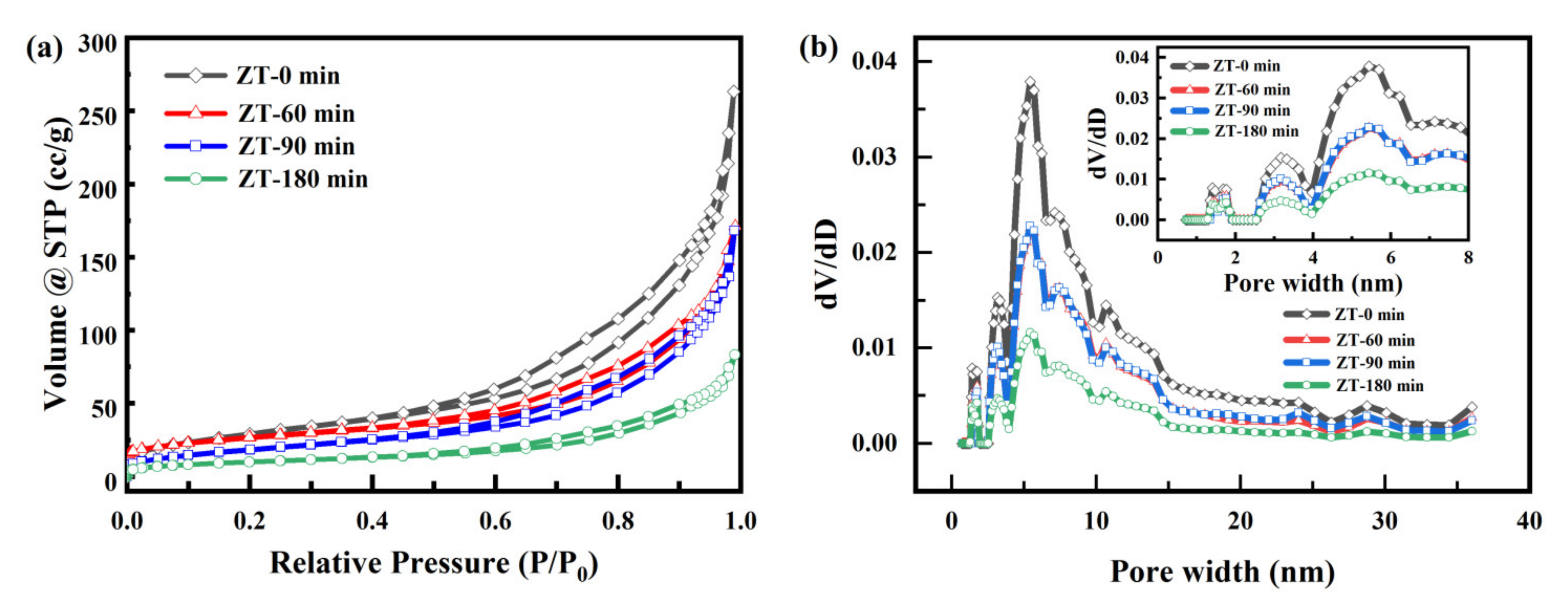
| Sample | SBET (m2/g) | Pore Volume (cm3/g) | Average Pore Diameter (nm) |
|---|---|---|---|
| ZT-0 min | 107.0 | 0.407 | 15.223 |
| ZT-60 min | 68.0 | 0.252 | 1.482 |
| ZT-90 min | 67.9 | 0.260 | 1.533 |
| ZT-180 min | 36.7 | 0.128 | 1.402 |
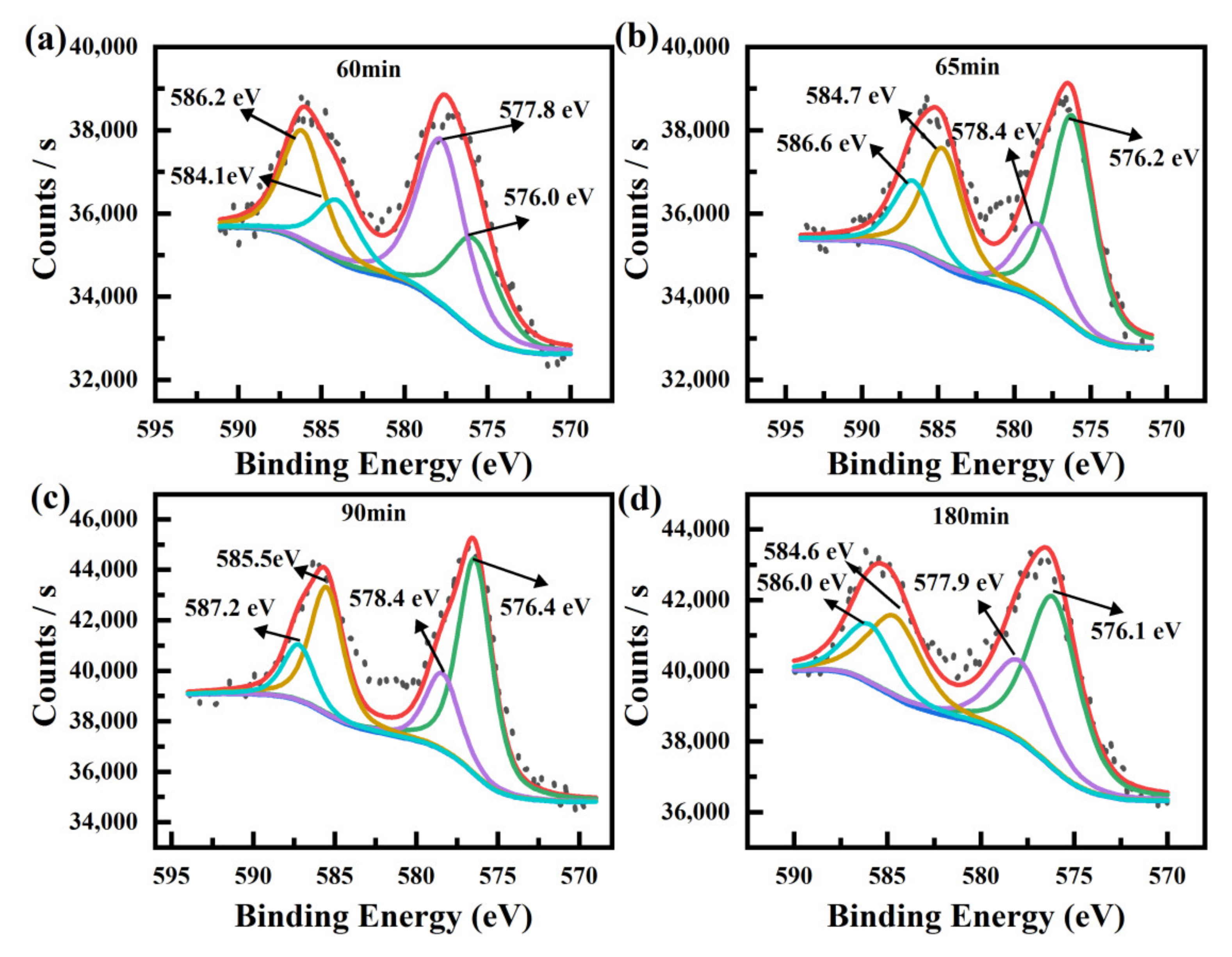
| Cr(III) | Cr(VI) | ||||
|---|---|---|---|---|---|
| Samples | Cr 2p1/2 (eV) | Cr 2p3/2 (eV) | Cr 2p1/2 (eV) | Cr 2p3/2 (eV) | Area Ratio of Cr(VI)/Cr(III) |
| K2Cr2O7 | 588.6 | 579.4 | |||
| Cr2O3 | 586.2 | 576.5 | |||
| Z100T200-60 min | 584.1 | 576.0 | 586.2 | 577.8 | 1.73 |
| Z100T200-65 min | 584.7 | 576.2 | 586.6 | 578.4 | 0.37 |
| Z100T200-90 min | 585.5 | 576.4 | 587.2 | 578.4 | 0.36 |
| Z100T200-180 min | 584.6 | 576.1 | 586.0 | 577.9 | 0.50 |
Publisher’s Note: MDPI stays neutral with regard to jurisdictional claims in published maps and institutional affiliations. |
© 2022 by the authors. Licensee MDPI, Basel, Switzerland. This article is an open access article distributed under the terms and conditions of the Creative Commons Attribution (CC BY) license (https://creativecommons.org/licenses/by/4.0/).
Share and Cite
Song, Y.; Lu, X.; Liu, Z.; Liu, W.; Gai, L.; Gao, X.; Ma, H. Efficient Removal of Cr(VI) by TiO2 Based Micro-Nano Reactor via the Synergy of Adsorption and Photocatalysis. Nanomaterials 2022, 12, 291. https://0-doi-org.brum.beds.ac.uk/10.3390/nano12020291
Song Y, Lu X, Liu Z, Liu W, Gai L, Gao X, Ma H. Efficient Removal of Cr(VI) by TiO2 Based Micro-Nano Reactor via the Synergy of Adsorption and Photocatalysis. Nanomaterials. 2022; 12(2):291. https://0-doi-org.brum.beds.ac.uk/10.3390/nano12020291
Chicago/Turabian StyleSong, Yu, Xi Lu, Zhibao Liu, Wenfei Liu, Ligang Gai, Xiang Gao, and Hongfang Ma. 2022. "Efficient Removal of Cr(VI) by TiO2 Based Micro-Nano Reactor via the Synergy of Adsorption and Photocatalysis" Nanomaterials 12, no. 2: 291. https://0-doi-org.brum.beds.ac.uk/10.3390/nano12020291