Article

A Facile Design of Solution-Phase Based VS2 Multifunctional Electrode for Green Energy Harvesting and Storage

1
Department of Nanotechnology and Advanced Materials Engineering, Sejong University, Seoul 05006, Korea
2
Division of Physics and Semiconductor Science, Dongguk University, Seoul 04620, Korea
*
Author to whom correspondence should be addressed.
Submission received: 25 December 2021 / Revised: 17 January 2022 / Accepted: 19 January 2022 / Published: 21 January 2022
(This article belongs to the Special Issue Characterization and Preparation of Electrocatalytic Nanomaterials)

Abstract

:
This work reports the fabrication of vanadium sulfide (VS2) microflower via one-step solvo-/hydro-thermal process. The impact of ethylene glycol on the VS2 morphology and crystal structure as well as the ensuing influences on electrocatalytic hydrogen evolution reaction (HER) and supercapacitor performance are explored and compared with those of the VS2 obtained from the standard pure-aqueous and pure-ethylene glycol solvents. The optimized VS2 obtained from the ethylene glycol and water mixed solvents exhibits a highly ordered unique assembly of petals resulting a highly open microflower structure. The electrode based on the optimized VS2 and exhibits a promising HER electrocatalysis in 0.5 M H2SO4 and 1 M KOH electrolytes, attaining a low overpotential of 161 and 197 mV, respectively, at 10 mA.cm−2 with a small Tafel slope 83 and 139 mVdec−1. In addition, the optimized VS2 based electrode exhibits an excellent electrochemical durability over 13 h. Furthermore, the superior VS2 electrode based symmetric supercapacitor delivers a specific capacitance of 139 Fg−1 at a discharging current density of 0.7 Ag−1 and exhibits an enhanced energy density of 15.63 Whkg−1 at a power density 0.304 kWkg−1. Notably, the device exhibits the capacity retention of 86.8% after 7000 charge/discharge cycles, demonstrating a high stability of the VS2 electrode.

Graphical Abstract

1. Introduction

Demand on renewable energy is growing impressively day-by-day. However, the heavy reliance on fossil fuels to fulfill the global energy demand has resulted many environmental issues [1]. Consequently, green and efficient energy resources for sustainable energy conversion and storage technologies are highly demandable. Hydrogen (H2) is a green energy that may be produced by water-electrolysis. Moreover, the waterlysis can be powered via a renewable energy, and this route of energy production can append a large contribution to achieve the goal on future global carbon neutrality program [2,3]. To produce hydrogen, water electrolysis is commonly catalyzed by noble metal-based catalysts such as those consisting of platinum (Pt) and iridium (Ir). However, these noble metals are rare and are very expensive, resulting the water-electrolysis unaffordable commercially [4,5]. Great efforts have been made to search for noble-metal-free catalysts with high activity and durability. To date, transition metal dichalcogenides (TMDs) [6], metal phosphides [7], MXenes [8] and MOFs [9,10] have been explored as suitable alternatives of Pt for the hydrogen evolution reaction (HER). For example, non-noble metal-based compounds such as MoS2, WS2, CoS2, NiSe2, CoSe2 [11], amorphous MoSx, VS2, CoP, Ni2P, FeP, WP, MoP|S, CoPS, NiP1.93Se0.07, and NiMo alloys have been studied as potential HER electrocatalysts [12,13]. Amongst, Vanadium disulfide (VS2) has been emerging as a promising electrocatalyst due to the fact that VS2 is a layered 2D-material with high HER catalytic activity both on the basal plane and edge [14,15,16].
On the other hand, another attractive characteristic of VS2 is its excellent electrical charge storing ability with a suitable conductivity for charge transport, which is vital for constructing supercapacitors (SCs). Tshifhiwa et al. reported the fabrication of an asymmetric supercapacitor cell based on porous activated carbon material as negative electrode and VS2 as positive electrode [17], Similarly, Feng et al. provided a detailed study of Metallic Few-Layered VS2 ultrathin nanosheets with less than five S–V–S atomic layers to design practical in-plane supercapacitors for the power sources in advanced ultrathin electronics [18]. Meyer et al. also reported carbon supported VS2 nanocomposites possessing the highest possible specific capacitance of 33 Fg−1 at a current density of 1 mA which is ascribed to the superior electrical conductivity [19]. SCs are simple electrochemical charge storing devices and have generated substantial research attention due to their facile fabrication process with less environmental concerns, and their high-power density with long cycling stability over the traditional secondary batteries [20]. As a potential SC material, VS2 is a hexagonal graphite-like structure composed of S-V-S layers having a large interlayer distance of 5.76 Å, which is suitable to guest Na+ and K+ ions in the interlayer spacing without a significant structural collapse [17,21]. In addition, the VS2 layered structure with suitable electrical conductivity also allows for their rapid electron transport during the charging/discharging cycles [14,21]. Overall, the excellent electrical conductivity, flexible interlayer interactions, high specific surface area with edge exposed atom, and a remarkably resilient, VS2 layered structure easily satisfy the requirement basis for developing a promising candidate for electrocatalyst and charge storing electrode-materials [18,22,23].
In this study, we designed a solution phase mediated VS2 consisting of microflowered structure, demonstrating the excellent performance on electrocatalytic HER in acidic (0.5 M H2SO4) and alkaline (1 M KOH) electrolytes together with the electrochemical energy storage capabilities. The optimized VS2 electrodes obtained via ethylene glycol added aqueous solvent synthetic route exhibited a highly ordered and smaller microflowered structures distributed uniformly over the larger electrode surface than the one deposited via pure aqueous or ethylene glycol mediated synthesis routes. As a result of their large surface area having abundant active sites and facile charge transport path, the optimized VS2 film-based electrodes demonstrated an excellent electrocatalytic HER and electrochemical supercapacitor performance.

2. Materials and Methods

All chemicals and reagents were used as obtained without further purification. Sodium orthovanadate (Na3VO4, 99%), thioacetamide (CH3CSNH2, 99%), ethylene glycol (HOCH2CH2OH, 99.8%) and nafion™ perfluorinated resin solution (5 wt.%) were purchased from Sigma Aldrich. Nickel foam (NF,1.6 mm thick) was acquired from Alantum Corporation (Seoul, South Korea). The NF substrate was cut into 1 × 5 cm2 pieces and washed for 10–15 min with ultrasonication (LVD-PC 540, 4Science.net, Seoul, Korea) at a frequency of 38.1 kHz for 10 min sequentially in 1 M HCl, deionized water, ethanol, and finally in acetone. The washed NF was dried in air naturally for 24 h at room temperature.

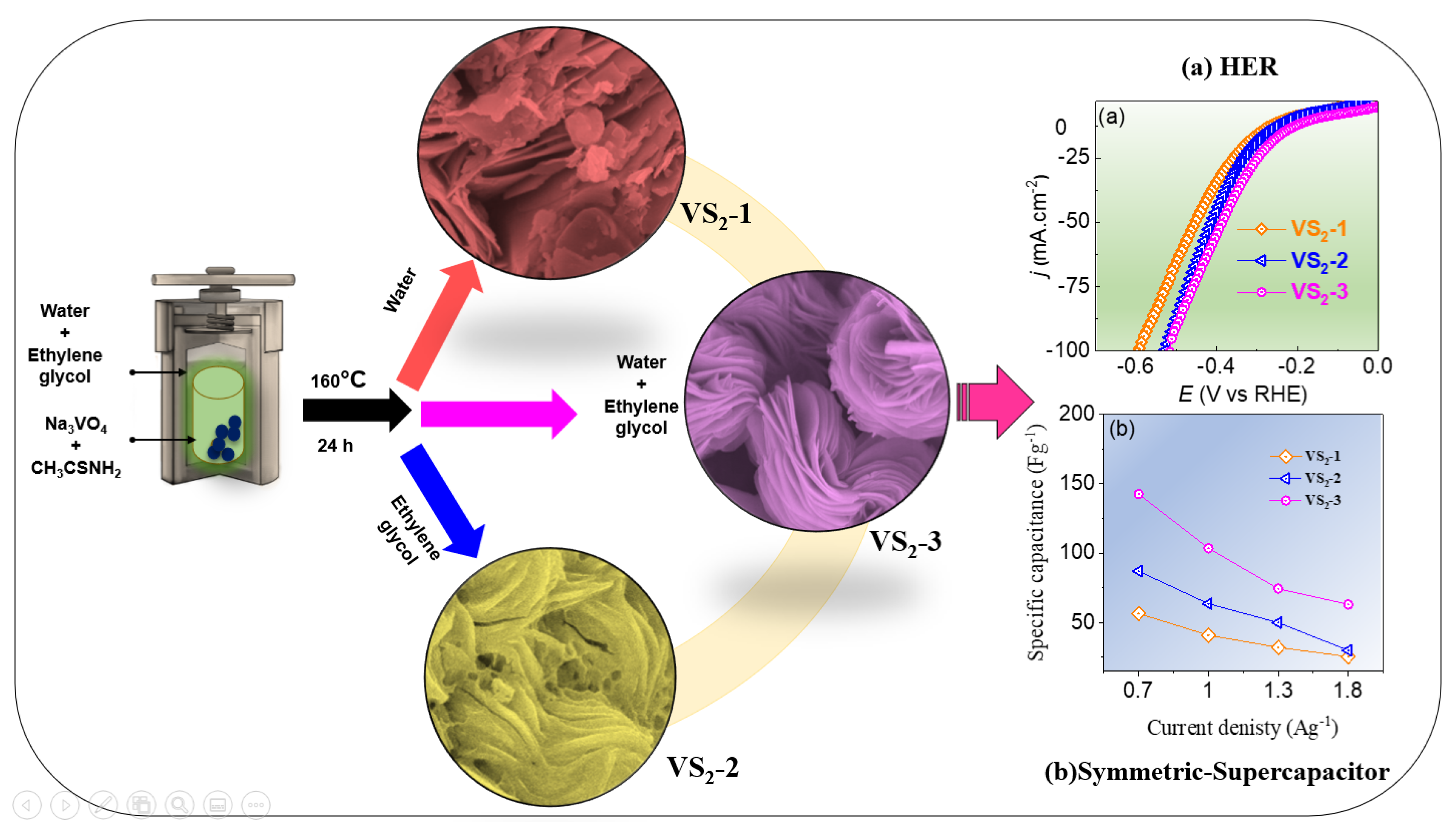
2.1. Synthesis of VS2 Microflower Structured Powder

To synthesize VS2, 0.1 M sodium orthovanadate and 0.5 M thioacetamide were dissolved in 30 mL DI water by ultrasonic agitation at a frequency of 38.1 kHz for 2 h to obtain a homogeneous solution. The resulting solution was then solvo-/hydro-thermally reacted for 24 h at 160 °C to obtain a black precipitate. The reaction product was naturally cooled to room temperature, then washed several times with DI water and ethanol. After that, the black products were centrifuged at 5000 rpm and finally dried under vacuum in a desiccator. This product is denoted as VS2-1 sample. Following a similar procedure, two more VS2 powder samples were synthesized for comparison with different solvent composition while keeping all other parameters as they were in the case of VS2-1 sample. The VS2 sample obtained using pure-ethylene is denoted as VS2-2 and the one obtained using 20 mL ethylene glycol and 10 mL DI water mixture solution is named asVS2-3 sample.

2.2. VS2-Based Electrode Fabrication

For catalysis test, the working electrode was prepared by drop casting the catalyst-ink onto a washed NF-substrate. The ink was prepared by mixing 6 mg of the as-synthesized VS2 powder in 0.5 mL of a mixture solution obtained from 6.93 mL of DI water-ethanol (3:1 volume ratio) and 5% Nafion (70 µL) solution via ultrasonic agitation at a frequency of 38.1 kHz in normal tap-water for 12 h to form a homogeneous ink. Following the formation of uniform ink, 285 µL was carefully loaded onto a 1 cm2 area of the NF substrate. The freshly prepared catalyst film was dried at room temperature for 24 h at 60 °C under vacuum in an oven. The mass loading of the VS2 was determined precisely using an inductively coupled plasma mass spectrometry (ICP-MS, NexION® 300D, PerkinElmer, Waltham, MA, USA).
A symmetric device was assembled to study the supercapacitor performance of the as-synthesized VS2 based electrodes. For assembly of the symmetric device, VS2-1, VS2-2, or VS2-3 based films on NF-substrate were utilized as positive and negative electrodes and 1 M aqueous solution of KOH was employed as electrolyte. A cellulose membrane was used as a separator, sandwiched between two the symmetric electrodes. The electrodes (VS2-1, VS2-2, and VS2-3) were prepared by mixing the carbon black and polyvinylidene (PVDF) with a mass ratio of 80:10:10, respectively. Then, the mixture was ground by adding a few drops of N-methyl-2-pyrrolidene (NMP) in a mortar until a uniform ink was obtained. The ink was dropped uniformly on the Ni foam and dried in a vacuum oven at 60 °C for 24 h.

2.3. Electrochemical Measurements

The multifunctional electrochemical characteristics of the VS2-1, VS2-2, and VS2-3 films on NF-substrates were performed using a three-electrode system (CHI 660D electrochemical instrument). HER experiments were performed in acidic (0.5 M H2SO4) and alkaline (1 M KOH) electrolytes at a scanning speed of 5 mV∙s−1 at room temperature (25 °C). Carbon rods and active ingredients (VS2-1, VS2-2, and VS2-3) coated nickel foams (NF) were used as the counter electrode and working electrode, respectively. The Ag/AgCl was employed as a reference electrode and a cyclic voltammetry (CV) was applied to activate the working electrode for several cycles until constant CV curves were obtained. A linear sweep voltammetry (LSV) was conducted for evaluation of HER and iR losses were compensated to the LSV data.
All the potentials were calibrated to the RHE potential scale using the Equation (1)
ERHE = EAg/AgCl + (0.197 + 0.0591pH).
Electrochemical impedance spectra (EIS) were measured in the frequency ranging from 0.1 Hz to 100 kHz.
For the supercapacitor-performance evaluation, cyclic voltammetry (CV), galvanostatic charge/discharge (GCD), and chronopotentiometry (CP) were measured. All electrochemical measurements were carried out using an SP-130 biologic electrochemical workstation at room temperature (25 °C).

3. Results and Discussion

3.1. Topographic, Crystal Structure and Chemical Composition Charaterization of VS2

The synthetic process of the VS2 microflower structured powder is schematically illustrated in Scheme 1. The VS2 microflower morphologies (VS2-1, VS2-2, and VS2-3) were obtained via solvo-/hydro-thermal reaction of Na3VO4·10H2O and thioacetamide (C2H5NS) at 160 °C for 24 h. The morphology of the fabricated VS2-1, VS2-2, and VS2-3 powder was characterized by field-emission scanning electron microscopy (FE-SEM, Hitachi SU8010, Seoul, South Korea) and the resulting images are shown in Figure 1a–f. Figure 1a,b shows randomly oriented nanosheets in a microflowered structure obtained using a pure-aqueous solvent. The diameter of these microstructures lies between 15 and 30 mm and the microstructures look similar to the assembly of flower-petals having 50 nm thick (inset Figure 1b). A similar layered nanosheet or nanoflake-structure of the VS2 was reported by hydrothermal synthesis in pure water [17,18,19].
While synthesizing in pure ethylene glycol solvent, the resulting VS2 microflowers were agglomerated, and the nanosheets were stacked one above another very closely (Figure 1c,d). A similar VS2 microflowers structure has been reported by Chen et al. while synthesizing in propylene glycol and ammonia solution [24]. In contrast, the VS2-3 based electrode, which was fabricated from the corresponding power sample synthesized in a mixture solvent of ethylene glycol and water, exhibited uniformly distributed microflowered structures with a diameter of about 1~2 µm (Figure 1e,f). This flower structure was consisted of an assembly of highly ordered unique sheet-like open flower-petal structure with a thickness of ~100 nm, which can be observed at a closer microscopic examination (inset Figure 1f). This highly ordered unique assembly would be beneficial for the improvement of catalytic and supercapacitor performance. It should be noted that the microstructure in this sample was approximately 4 and 15 times smaller than those achieved in a pure-ethylene glycol and pure-water-mediated process, respectively. This is due to the fact that in comparison to the pure water-mediated reaction process, the addition of ethylene glycol lowers the solubility and mobility of the reactants, hindering the crystal formation [25]. As a result, smaller flowers were achieved, which would be beneficial to increase the concentration of active catalytic sites. Furthermore, due to the reductive nature of the alcohol moiety, ethylene glycol can help to minimize the intrinsic defect concentration of the VS2 structure, and impurity, such as vanadium oxidation, formation can be prevented during synthesis [26,27]. Remarkably, each nanosheet in VS2-3 sample is linked to the next in a highly ordered fashion, generating an open microflower-like structure. This structural feature would be advantageous for free flow of charges between the structures and the electrolyte, thereby enhancing the charge transfer kinetics in electrolysis and supercapacitors. Furthermore, the VS2-3 sample contains a consistent distribution of microstructures of comparable size and shape.
Transmission electron microscopy (TEM, JEOL-3000F, Seoul, Korea) was also used to demonstrate the formation of the microflowered structure. The TEM depiction of a VS2-3 sample obtained from an ethylene glycol/DI water solvent combination is displayed in Figure 2a, which reveals the petal-shaped sheet. The high-resolution TEM image the corresponding inverse FFT spectrum (Figure 2b,c) generated using the ImageJ computer-program (1.8.0_172, Seoul, Korea) indicates a lattice spacing of 0.15 nm, which corresponds to the characteristic (111) crystal-line lattice fringes of VS2. Furthermore, the polycrystalline character of the sample is shown by the selected area electron diffraction (SAED) pattern in Figure 2d. The scanning transmission electron microscopy (STEM) image and elemental mapping demonstrate that the V and S elements were distributed consistently throughout the microflowered structure, with no signs of V or S aggregation (Figure 2e,f).
Furthermore, Figure 3a shows the XRD spectra of the as-fabricated VS2-1, VS2-2, and VS2-3 powder samples along with the reference patterns of VS2 imported from the JCPDS file no. 01-089-1640. The XRD spectra are well matched to the reference patterns and display various diffraction peaks of the polycrystalline nature. This finding confirms the existence of the hexagonal phase of VS2. Based on the standard powder diffraction card, the diffraction peaks (black and blue spectrum) at 2θ = 15.3°, 31.9°, 35.7°, 45.5°, and 47.31° can be indexed to the reflection of (001), (100), (011), (012), and (003) planes of VS2, respectively [23]. In addition, the VS2-3 sample (magenta color spectrum) also shows two additional different peaks at 58.3° and 59.8 that can be associated with the (103), and (111) planes. These additional VS2 phases could further enhance the catalytic site densities in sample VS2-3. The corresponding hexagonal crystal phase structure of VS2 in a space-filling model is displayed in Figure 3b. Raman analysis was conducted for the VS2-1, VS2-2, and VS2-3 electrodes in the range of 200–800 cm−1 as shown in Figure 3c. The three well-defined peaks located at 280 and 405 cm−1 can be ascribed to the Eg vibration (S dumbbells librational) mode and the out-of-plane (Ag) vibration mode of the VS2, respectively, while the peak at 688 cm−1 corresponds to the rocking and stretching vibrations of V–S bonds or their combination [28]. The binding states of the constitutional elements in the optimized VS2-3 sample were studied using X-ray photoelectron spectroscopy (XPS), as illustrated in Figure 3d–f. A typical XPS survey spectrum of the VS2-3 sample shows that the VS2 nanoflower is mostly constituted of V and S, with a small O 1s peak resulting from surface oxidation of VS2 in air. The high-resolution spectra of V 2p and S 2p are displayed in Figure 3e,f, respectively. The high-resolution V 2p XPS spectrum can be deconvoluted into a doublet with peaks located at the binding energies of 524.8 eV and 517 eV, respectively, for the V 2p1/2 and V 2p3/2. This suggests that vanadium in the +4 oxidation state. Similarly, the high-resolution S 2p spectra can be deconvoluted to a doublet with the centers located at the binding energies of 163.6 eV and 162.4 eV, which correspond to the S 2p1/2 and S 2p3/2, respectively. This reveals the divalent sulfide (S2−), and the XPS finding further confirms the VS2 (1:2) composition of the sample [29]. In Figure S1, the related EDX spectrum also demonstrates that the V and S stoichiometry is about 1:2, confirming that the synthesized microflower is constituted of VS2. Moreover, the VS2 particle loading on the NF substrate was determined precisely using ICP-MS, which reveals 3.22 mg cm−2, and this sample also demonstrated a V to S atomic ratio of 0.5204, revealing 1:2 stoichiometry of V and S.

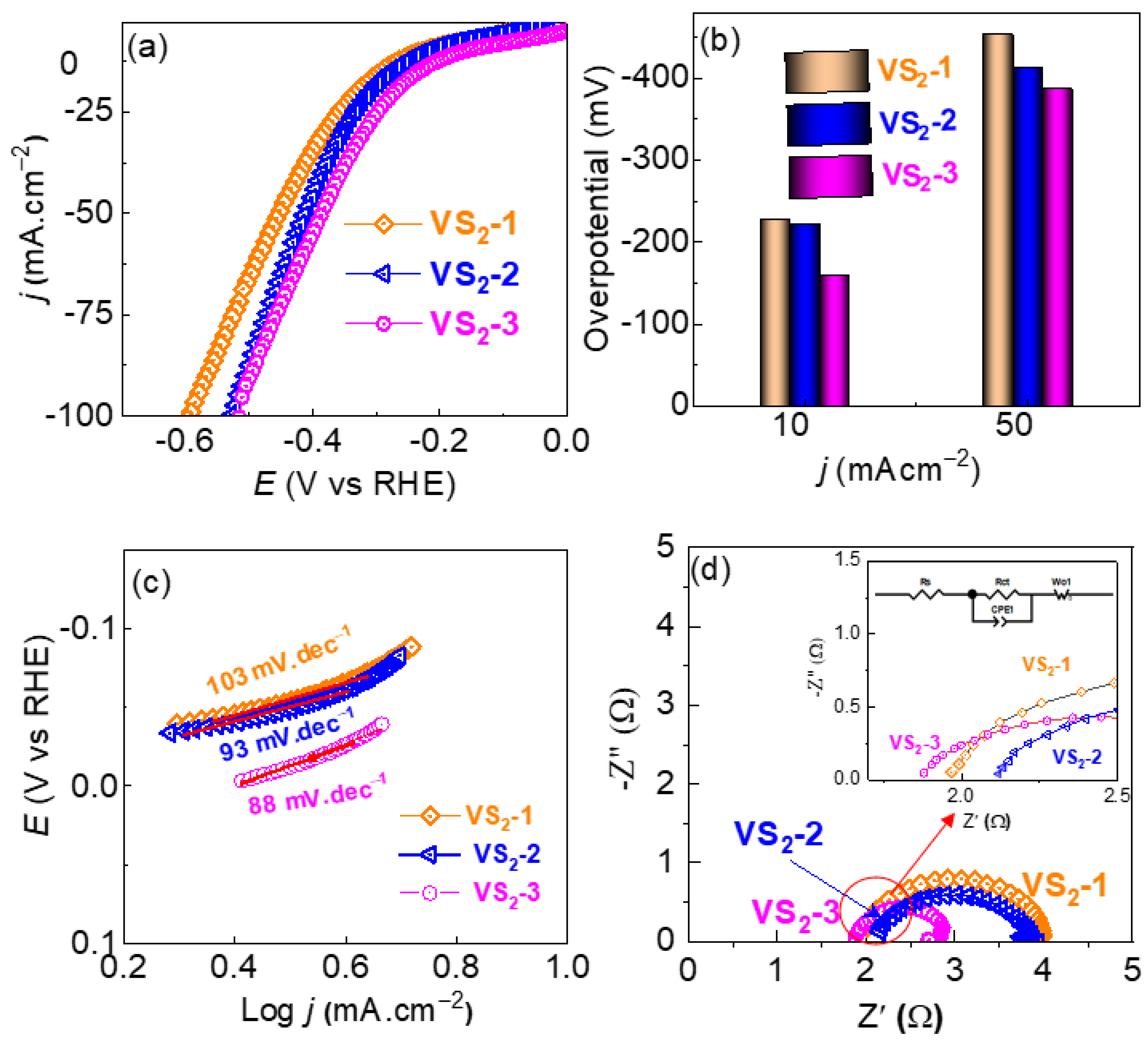
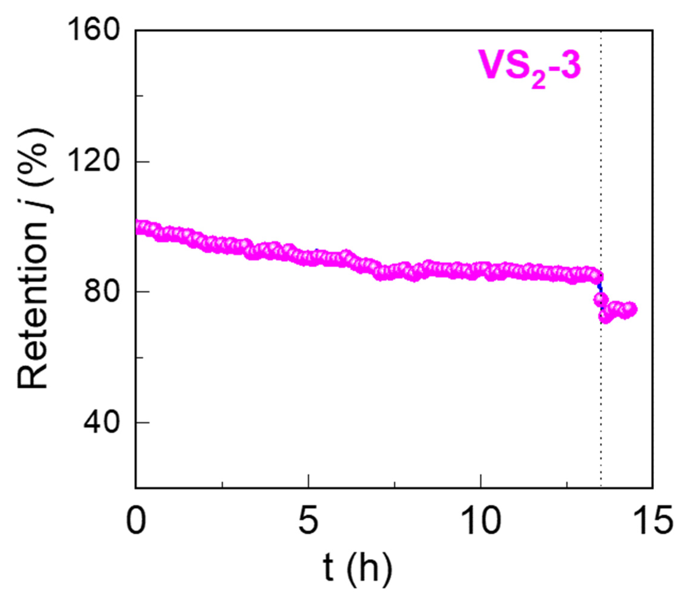
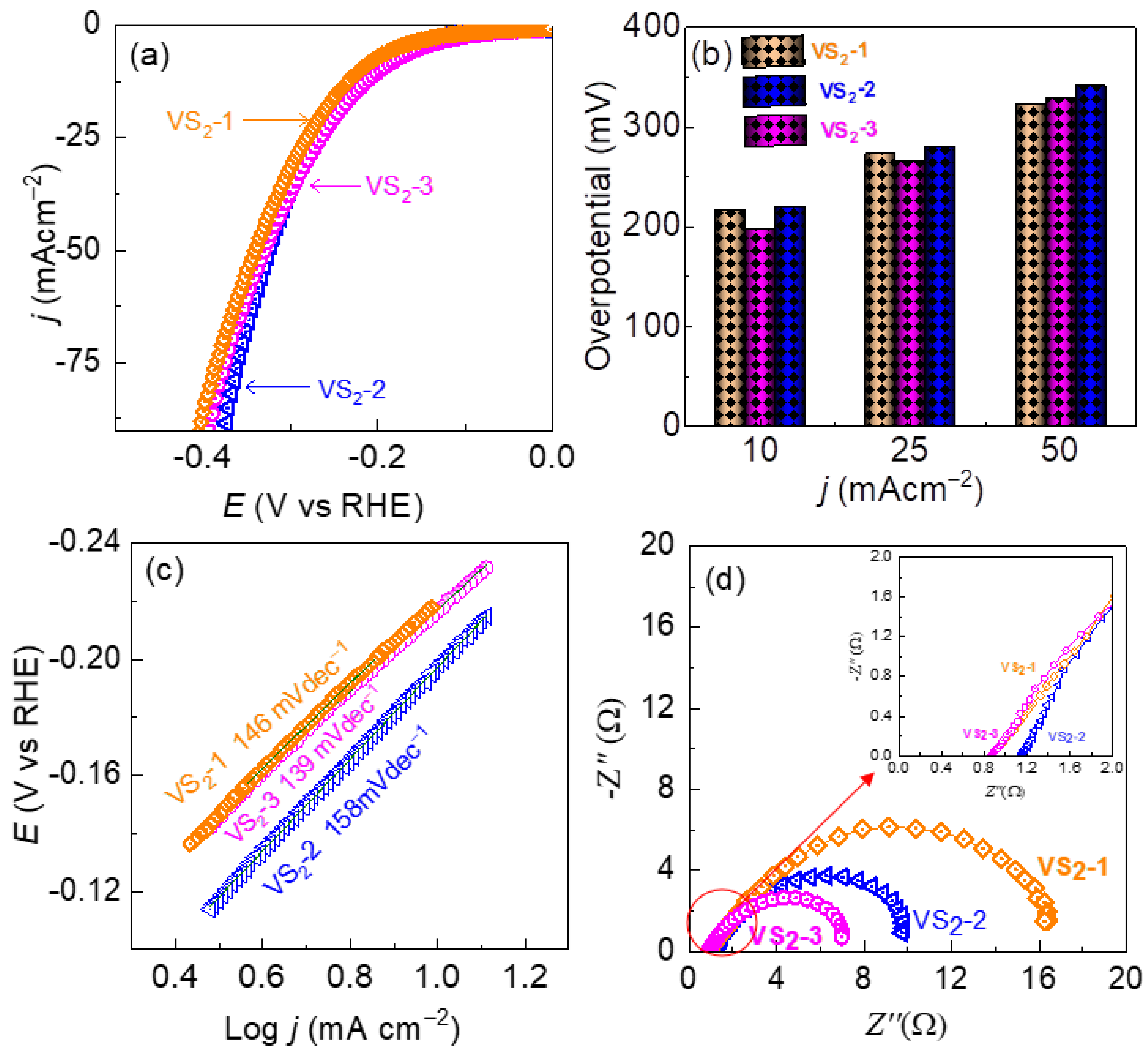
3.2. HER Performance of VS2 Electrodes in Acidic and Alkaline Electrolyte

The electrocatalytic performances of the VS2 based electrodes were assessed for HER using the LSV in a standard three-electrode cell containing 0.5 M H2SO4 or 1 M KOH aqueous solution as acidic and alkaline electrolyte, respectively. The LSV data were measured at a scan rate of 5 mVs−1 and the LSV curves were iR-corrected using the solution resistance acquired from the EIS measurement. Figure 4a, shows the polarization curves of the VS2-1, VS2-2, and VS2-3 samples in a 0.5 H2SO4 aqueous electrolyte. The VS2-1 electrode shows the HER overpotential of 227 mV at a current density of 10 mA cm−2. The overpotential is lower for the VS2-2 electrode obtained from the pure-ethylene glycol-based synthesis route, displaying HER overpotential of 222 at 10 mAcm−2. In contrast, the catalyst fabricated utilizing ethylene glycol and water solvent (VS2-3) exhibits a relatively lower overpotential of 161 mV at 10 mAcm−2. This illustrates that the addition of ethylene into water to synthesize VS2-3 catalyst substantially boosted its intrinsic activity. As explained in the earlier section, this is owing to the fact that the addition of ethylene glycol hinders crystal formation and prevents oxide formation when compared to a pure aqueous-mediated process. This led to the highly ordered unique sheet-like open flower-petal microstructure (Figure 1f), thereby boosting the concentration of active catalytic sites. For the performance evaluation, the overpotential was obtained by subtracting the thermodynamic potential of HER (i.e., 0.00 V vs. RHE) from that of the experimentally obtained potential of the working electrode at a given current density. Figure 4b displays a comparative HER overpotential profiles vs. current densities. The VS2-3 based electrode, as shown in Figure 4b, has a lower overpotential of 161 and 386 mV at 10, and 50 mAcm−2, respectively. This implies that a relatively lower driving energy is needed to drive the HER for the VS2-3 sample. In addition, the Tafel plots, presented in Figure 4c, revealed a reasonably low Tafel slope of 88 mV dec−1 with a higher exchange current density (J0) of 7.294 × 10⁻⁵. This finding reveals the facile HER kinetic for the VS2-3 electrode and a smaller amount of driving energy was required towards HER, which is lower than the VS2-2 (93 mVdec−1, J0 = 1.640 × 10⁻⁵) and VS2-1 (103 mVdec−1, J0 = 3.863 × 10⁻⁶) based electrodes, respectively. The charge transport nature of the electrodes was evaluated using electrochemical impedance spectroscopy (EIS), and the resulting Nyquist plot fitted with an analogous circuit is shown in Figure 4d. The relatively low solution resistance (Rs = 1.8) and charge-transfer resistance (Rct = 2.41 Ω) experienced by the VS2-3 electrode indicates the close contact between the VS2-3 active species and NF substrate, and a facile charge transport between the electrolyte and electrode with compared to the VS2-1 (Rs = 1.9 Ω, Rct = 2.91 Ω) and VS2-2 (Rs = 2.1 Ω, Rct = 3.08 Ω) based electrodes. The detailed EIS parameters including constant phase element (CPE) and diffusion impedance (Zw) are shown in Table S1. The electrochemical surface area (ECSA) of the catalyst is one of the key factors in electrocatalysis and was computed in terms of the commonly used double-layer charging currents in the non-Faradic regions. The VS2-1 (4.0 mFcm−2) and VS2-2 (4.1 mFcm−2) samples showed similar double-layer capacitance while the VS2-3 (10 mFcm−2) sample exhibited a significantly higher double-layer capacitance (Figure S2). The computed double-layer capacitance is directly related to the ECSA, which is further related directly to the available active electrocatalytic sites. This implies that the VS2-1 sample had significantly higher catalytic HER sites compared with the other two samples. As a result, the VS2-1 based electrode offered the lower overpotential and faster HER kinetics. Apart from the overpotential and HER kinetic, long-term electrochemical stability of the catalyst-based electrode is also a key factor determining the practical applicability of the catalyst. The long-term electrochemical durability of the VS2-3 catalyst-based electrode, which demonstrated a high HER performance amongst other catalyst-based electrodes, was examined via chronoamperometry (j vs. t measurement). The HER current density remains fairly stable for a long run over 13 h and has shown the retention of about 85% of the initial current density at the end of 13.43 h. Beyond this, the electrode started to degrade as shown in Figure 5.
In addition, as shown in Figure 6a, the HER performance of the catalyst was also investigated in 1 M KOH aqueous electrolyte. In line with the HER performance in acidic electrolyte, amongst all, the VS2-3 based electrode demonstrated a lower HER overpotential of 197 mV to achieve the current density of −10 mAcm−2. As revealed by Figure 6a, this HER activity is relatively lower than that of the VS2-1 and VS2-2 based electrodes. This finding implies that the solvents used in the synthesis of VS2 microstructures play a key role in determining the HER activity via manipulation of microstructure of the catalyst, which can favor for enhancement of the catalytic active sites. Figure 6b depicts a comparative HER overpotential profiles vs. current densities. The VS2-3 based electrode, as shown in Figure 6b, has a relatively lower overpotential of 197, 265, and 329 mV at 10, 25, and 50 mAcm−2, respectively. Furthermore, the Tafel slope exhibited by the VS2-3 based electrode is 139 mVdec1, which is lower than that exhibited by the VS2-1 (146 mVdec−1) and VS2-2 (158 mVdec−1) based electrodes (Figure 6c). This finding implies that the HER kinetics on the VS2-3 electrode is faster than on the other electrodes. Tables S2 and S3 demonstrate a comparison of HER performance of the VS2-3/NF electrode with other previously published representative transition metal-based electrocatalysts. To further support this finding on HER kinetics, EIS was measured in 1 M KOH electrolyte, and the resulting Nyquist plot is shown in Figure 6d. In comparison to the VS2-1 and VS2-2 based electrodes, the VS2-3 based electrode exhibited a relatively smaller charge-transfer resistance (Rct) as shown by the smaller semicircle in Figure 6d. This implies the facile charge transfer between the VS2-3 based electrode and electrolyte indicating the faster HER kinetic.

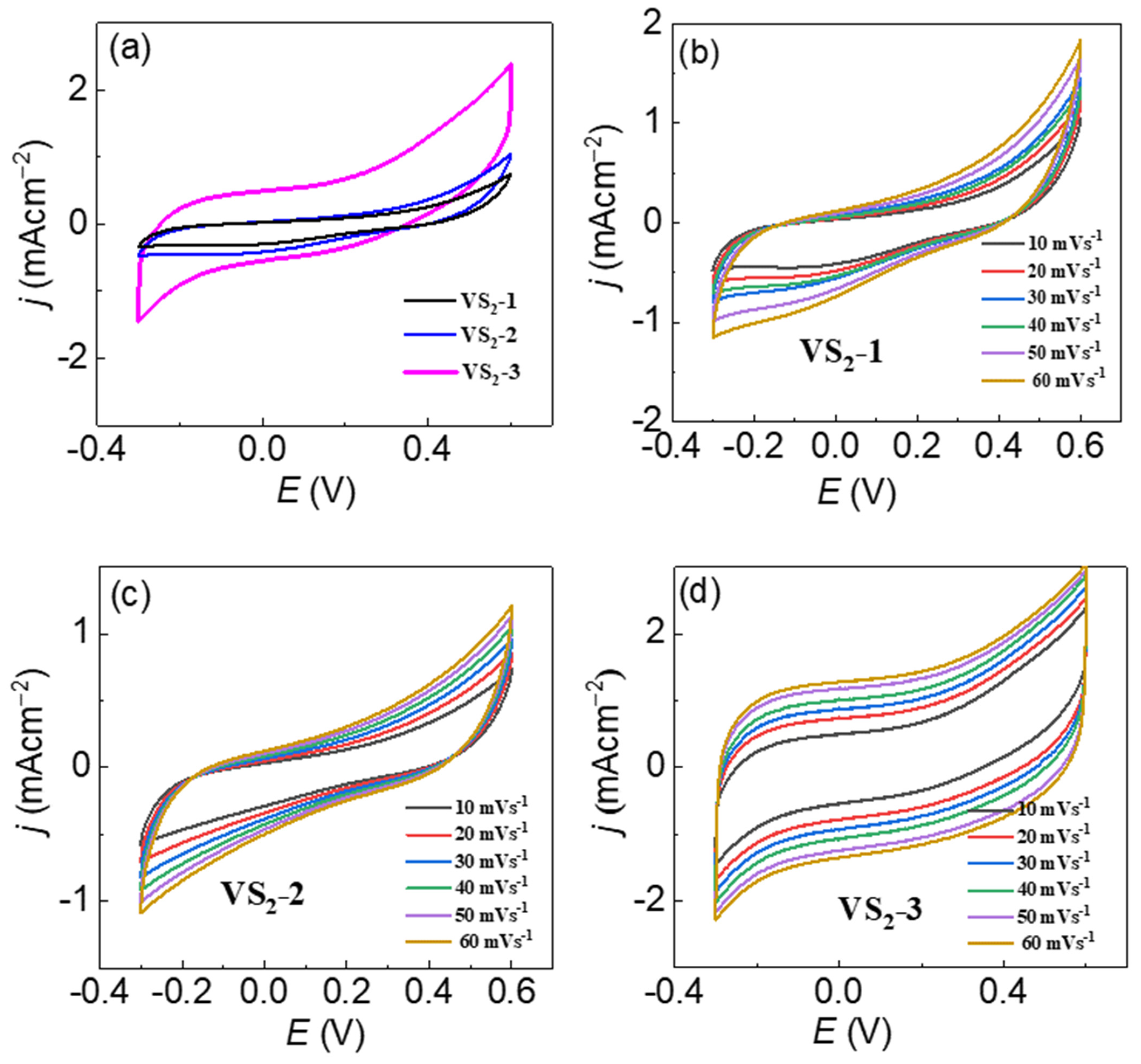
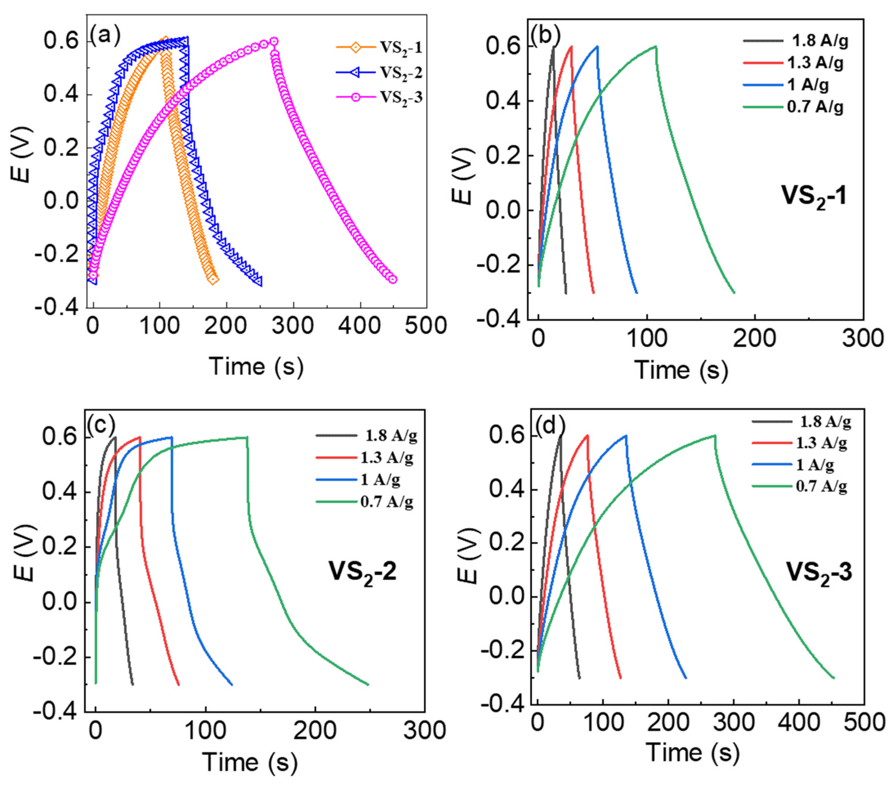
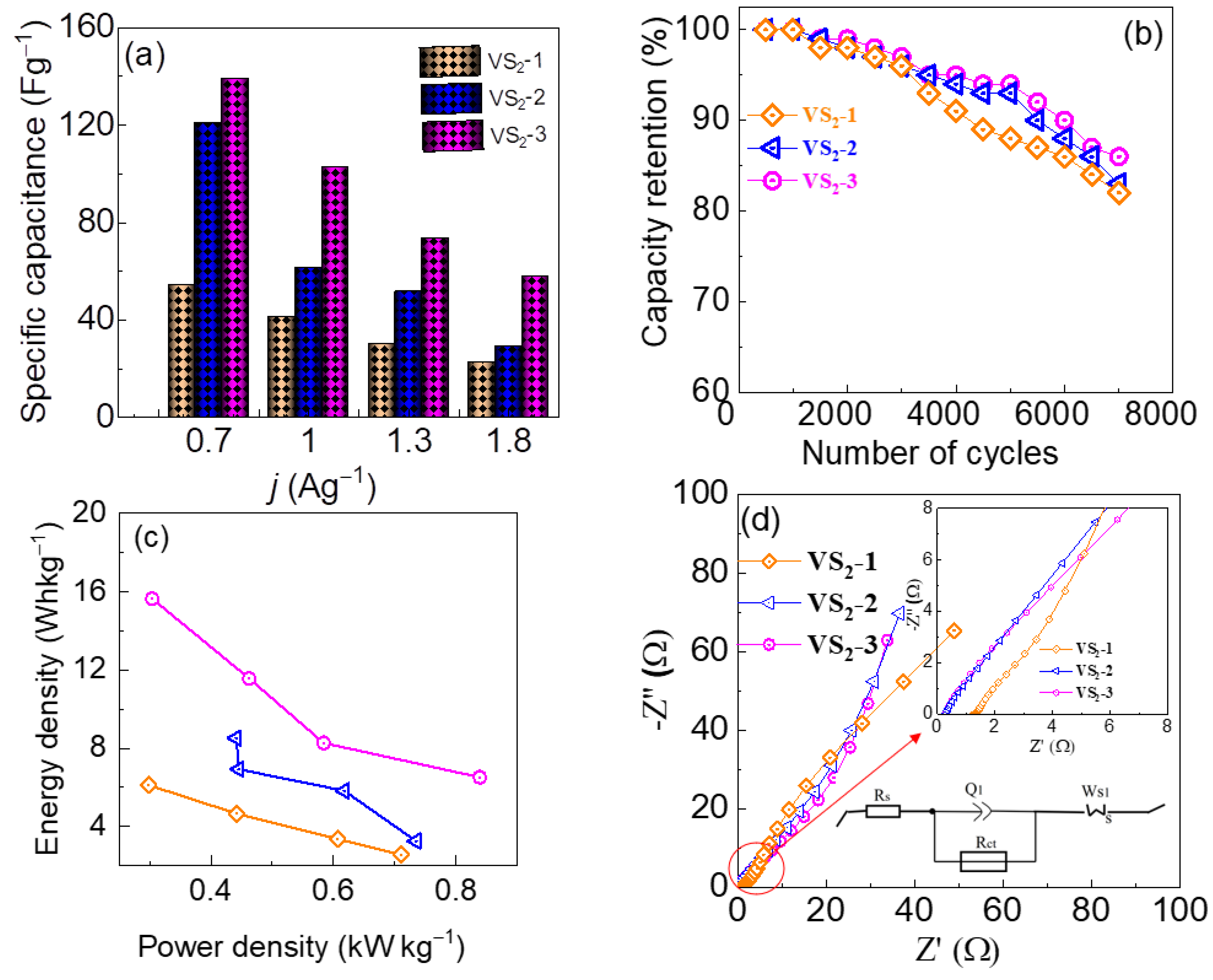
3.3. Supercapacitor Performance of VS2 in Symmetric Device-Configuration

A symmetric device is employed for the evaluation of the electrochemical performance of VS2 electrodes. For this, the as-prepared electrodes were utilized as cathode and anode with 1 M KOH as electrolyte. Cyclic voltammetry (CV) was examined at the voltage ranging between −0.3 to 0.6 V, as shown in Figure 7a–d. The CV curves for the device prepared from the VS2-1, VS2-2, VS2-3 based electrodes are depicted in Figure 7a. The VS2-3 electrode-based device clearly exhibited a high current response which was an about 2-folds integral area compared with the VS2-1 and VS2-2 electrode-based devices. The CV curves of all the VS2 based devices exhibited a notably similar shape resembling to the rectangular nature of an electric double layer capacitor (EDLC). However. It should be noted that the CV curves are not ideally rectangular. Although, no distinctive redox peaks in the CV curves can be observed, the curves are, in fact, deviated from the pure-EDLC derived ideal rectangular shape. This indicates the possibility of occurrence of reversible redox reactions within the voltage window under study. In general, the charge storage mechanism can be classified into the diffusion-controlled faradaic components originated from the pure redox reactions taking place by the diffusion of active ions from electrolyte to the electrode, surface-bound rapid faradaic components originated from the redox reaction of the surface adsorbed active ions on the electrode surface, and the surface-bound rapid non-faradaic components resulting from the material’s EDLC behavior [30,31].
Further, the CV curves at various sweep rates (10 mVs−1 to 60 mVs−1) are recorded in Figure 7b–d. Based on the highly ordered and open petal assembled microflower-like structures of VS2 in VS2-3 sample, a rapid to-and-fro trafficking of K+ ions facilitated by the 2D multi-layered VS2 nanosheets can be assumed in the VS2-3 based symmetric device. As a consequence, the CV curve of the VS2-3 based symmetric device maintains a similar shape even at the higher scan rates such as 60 mVs−1, indicating the excellent reversibility of the symmetric device. In contrast, the VS2-1 and VS2-2 based symmetric devices exhibited the CV curves deviated largely from the rectangular shape, showing severe polarization when the scan rate was increased from 10 to 60 mVs−1. The deviation in the shape of CV curves is attributed to the redox reaction across the electrode-electrolyte interface, which corresponds to the contribution from the typical characteristics of the pseudo-capacitance. Notably, when the CV loops were repeated for 100 cycles at the 10 mVs−1, unperturbed shape of the CV curve even after a colossal number of cycles were obtained in the VS2-3 based symmetric device, exhibiting an about of 98% cyclic retentions. This preliminary finding reveals a long-term stability and higher rate capability of the VS2-3 based symmetric device.
For in-depth evaluation of the device performance, galvanostatic charging discharging (GCD) has been analyzed at 0.7 Ag−1 and the results are presented in Figure 8a. The VS2-3 based symmetric device exhibited longest discharging time compared with the others, thereby leading to the higher specific capacitance (Cs), which is consistent with the CV curves. The symmetric device shows smaller iR drops particularly at the lower current density of 0.7 Ag−1, implying the low internal resistance of the symmetric device. Moreover, the GCD curves for the VS2-1, VS2-2 and VS2-3 based devices were examined at the various current densities, and are depicted in Figure 8b–d. Here, Cs was determined through GCD curve using the following Equation (2).
C s = I d i s × Δ t d i s Δ V
wherein, Idis is the discharging current density, ∆tdis is the discharging time, and ∆V is the voltage window. The VS2-3 symmetric device shows Cs of 139 Fg−1 which is higher than that of VS2-2 (120 Fg−1) and VS2-1 (54 Fg−1) at the discharging current density of 0.7 Ag−1 (Figure 9a). The long-term stability of the symmetric device is a key parameter for practical application of the supercapacitors, which was investigated by the repeated GCD measurements at a current density of 0.7 Ag−1 for 7000 cycles, as presented in Figure 9b. The capacity retention was almost 100% at the end of 1000 cycles, beyond which it decreased gradually. Notably, the VS2-3 based symmetric device showed remarkable capacity retentions of 86% even at the end of 7000 cycles revealing the capacitance degradation of only about 14%, which is lower than that of VS2-2 (17%) and VS2-1 (18%) based devices.
The energy and power density of the symmetric devices were determined utilizing the following equation:
E = C s × Δ V 2 2
P = E Δ t d i s
where, E and P are energy and power density, respectively. The energy density as a function of power density of the symmetric VS2 based devices is shown in Figure 9c. The VS2-3 based device exhibited a maximum energy density of 15 Whkg−1 at a power density of 0.304 kWkg−1. Furthermore, EIS was measured to investigate the charge transfer behaviors of the VS2-1, VS2-2, and VS2-3 electrodes in the frequency ranging from 100 mHz to 200 kHz under an open circuit potential (Figure 9d). The variables Rs and Rct represent the electrochemical system resistance (i.e., all resistances including electrolyte ionic resistance, substrate intrinsic resistance, and contact resistance between the active material and current collector) and charge transfer resistance, respectively. The Rs and Rct of the VS2-3 device-based electrodes are smaller than those of VS2-1, VS2-2 based devices (Table S4), indicating that the VS2-3 based material in the device transport current fluently to the current collector than the other VS2 materials. This EIS data supports the higher performance of the VS2-3 based symmetric device.

4. Conclusions

A solvo-/hydro-thermal route was employed to design a solution-phase mediated layered VS2 microflower structured materials in a mixture of ethylene glycol and water as the reaction media. The optimized VS2-3 based electrode obtained from the ethylene glycol and water mixed solvent-mediated synthesis route demonstrated a high catalytic performance for HER in both acidic and alkaline electrolytes containing 0.5 M H2SO4 or 1 M KOH. This finding demonstrates the ability of the VS2 to catalyze HER in a wide pH range of electrolyte. In addition, the optimized VS2-3 electrode-based symmetrical supercapacitor exhibited a specific capacitance of 139 Fg−1 with an energy density of 15 Whkg−1. Moreover, the device showed an excellent capacity retention of 86.8% of the initial value at the end of 7000 charge/discharge cycles, demonstrating a high stability of the VS2 electrode. The strong electrocatalytic and supercapacitor performance is attributed to the crystalline microflower structure of VS2 consisting of highly ordered nanosheet layers. This study proposes a straightforward construction technique for green hydrogen energy production and green energy storage devices which can contribute to the future global carbon neutrality program.

Supplementary Materials

The following supporting information can be downloaded at: https://0-www-mdpi-com.brum.beds.ac.uk/article/10.3390/nano12030339/s1, Figure S1: Energy-dispersive X-ray spectroscopy (EDX), Figure S2: (a–c) Cyclic voltammetry (CV) curves of the VS2-1, VS2-2, VS2-3 electrodes in the non-faradic region, and (d) their corresponding scan rate versus current density plots of the electrodes. Table S1: EIS parameters extracted from Nyquist plots of the VS2 samples. Table S2: Comparison of HER performance of the VS2-3 catalyst with the recently reported transition metal-based metal catalysts in acidic (0.5 M H2SO4) electrolyte. Table S3: Comparison of HER performance of the VS2-3 catalyst with the recently reported transition metal-based metal catalysts in alkaline (1M KOH) electrolyte. Table S4: EIS parameters extracted from Nyquist plots of the VS2 samples.

Author Contributions

Conceptualization, methodology, writing—original draft preparation; S.A.P. and N.K.S.; formal analysis data curation I.R.; validation, data curation, S.H.; formal analysis, resources, Y.-S.S. and J.J.; project administration, funding acquisition, H.I. and H.K. All authors have read and agreed to the published version of the manuscript.

Funding

This research was funded by National Research Foundation (NRF) of Korea for their financial support (grant no. 2018R1D1A1B07049046). Also, this work was supported by the faculty research fund of Sejong University in 2022.

Institutional Review Board Statement

Not applicable.

Informed Consent Statement

Not applicable.

Data Availability Statement

Data can be available upon request from the authors.

Conflicts of Interest

The authors declare no conflict of interest.

References

  1. IPCC Global Warming of 1.5 °C; An IPCC Special Report on the Impacts of Global Warming of 1.5 °C Above Pre-Industrial Levels and Related Global Greenhouse Gas Emission Pathways, in the Context of Strengthening the Global Response to the Threat of Climate Change; IPCC-Sr15: Geneva, Switzerland, 2018; Volume 2, pp. 17–20.
  2. Noussan, M.; Raimondi, P.P.; Scita, R.; Hafner, M. The role of green and blue hydrogen in the energy transition—A technological and geopolitical perspective. Sustainability 2021, 13, 298. [Google Scholar] [CrossRef]
  3. Hanley, E.S.; Deane, J.P.; Gallachóir, B.P.Ó. The role of hydrogen in low carbon energy futures—A review of existing perspectives. Renew. Sustain. Energy Rev. 2018, 82, 3027–3045. [Google Scholar] [CrossRef]
  4. Wei, C.; Rao, R.R.; Peng, J.; Huang, B.; Stephens, I.E.L.; Risch, M.; Xu, Z.J.; Shao-Horn, Y. Recommended Practices and Benchmark Activity for Hydrogen and Oxygen Electrocatalysis in Water Splitting and Fuel Cells. Adv. Mater. 2019, 31, 1806296. [Google Scholar] [CrossRef]
  5. McCrory, C.C.L.; Jung, S.; Peters, J.C.; Jaramillo, T.F. Benchmarking heterogeneous electrocatalysts for the oxygen evolution reaction. J. Am. Chem. Soc. 2013, 135, 16977–16987. [Google Scholar] [CrossRef] [PubMed]
  6. Wang, F.; Shifa, T.A.; Zhan, X.; Huang, Y.; Liu, K.; Cheng, Z.; Jiang, C.; He, J. Recent advances in transition-metal dichalcogenide based nanomaterials for water splitting. Nanoscale 2015, 7, 19764–19788. [Google Scholar] [CrossRef] [PubMed]
  7. Ying, J.; Wang, H. Strategies for Developing Transition Metal Phosphides in Electrochemical Water Splitting. Front. Chem. 2021, 9, 700020. [Google Scholar] [CrossRef] [PubMed]
  8. Bai, S.; Yang, M.; Jiang, J.; He, X.; Zou, J.; Xiong, Z.; Liao, G.; Liu, S. Recent advances of MXenes as electrocatalysts for hydrogen evolution reaction. NPJ 2D Mater. Appl. 2021, 5, 78. [Google Scholar] [CrossRef]
  9. Shrestha, N.K.; Patil, S.A.; Cho, S.; Jo, Y.; Kim, H.; Im, H. Cu-Fe-NH2 based metal-organic framework nanosheets: Via drop-casting for highly efficient oxygen evolution catalysts durable at ultrahigh currents. J. Mater. Chem. A 2020, 8, 24408–24418. [Google Scholar] [CrossRef]
  10. Patil, S.A.; Cho, S.; Jo, Y.; Shrestha, N.K.; Kim, H.; Im, H. Bimetallic Ni-Co@hexacyano nano-frameworks anchored on carbon nanotubes for highly efficient overall water splitting and urea decontamination. Chem. Eng. J. 2021, 426, 130773. [Google Scholar] [CrossRef]
  11. Rabani, I.; Hussain, S.; Vikraman, D.; Seo, Y.S.; Jung, J.; Jana, A.; Shrestha, N.K.; Jalalah, M.; Noh, Y.Y.; Patil, S.A. 1D-CoSe2 nanoarray: A designed structure for efficient hydrogen evolution and symmetric supercapacitor characteristics. Dalt. Trans. 2020, 49, 14191–14200. [Google Scholar] [CrossRef]
  12. Wang, M.; Zhang, L.; He, Y.; Zhu, H. Recent advances in transition-metal-sulfide-based bifunctional electrocatalysts for overall water splitting. J. Mater. Chem. A 2021, 9, 5320–5363. [Google Scholar] [CrossRef]
  13. Landers, A.T.; Fields, M.; Torelli, D.A.; Xiao, J.; Hellstern, T.R.; Francis, S.A.; Tsai, C.; Kibsgaard, J.; Lewis, N.S.; Chan, K.; et al. The Predominance of Hydrogen Evolution on Transition Metal Sulfides and Phosphides under CO2 Reduction Conditions: An Experimental and Theoretical Study. ACS Energy Lett. 2018, 3, 1450–1457. [Google Scholar] [CrossRef] [Green Version]
  14. Liu, Y.Y.; Xu, L.; Guo, X.T.; Lv, T.T.; Pang, H. Vanadium sulfide-based materials: Synthesis, energy storage and conversion. J. Mater. Chem. A 2020, 8, 20781–20802. [Google Scholar] [CrossRef]
  15. Zhao, M.; Yang, M.; Huang, W.; Liao, W.; Bian, H.; Chen, D.; Wang, L.; Tang, J.; Liu, C. Synergism on Electronic Structures and Active Edges of Metallic Vanadium Disulfide Nanosheets via Co Doping for Efficient Hydrogen Evolution Reaction in Seawater. ChemCatChem 2021, 13, 2138–2144. [Google Scholar] [CrossRef]
  16. Wang, Z.; Xu, W.; Yu, K.; Feng, Y.; Zhu, Z. 2D heterogeneous vanadium compound interfacial modulation enhanced synergistic catalytic hydrogen evolution for full pH range seawater splitting. Nanoscale 2020, 12, 6176–6187. [Google Scholar] [CrossRef]
  17. Masikhwa, T.M.; Barzegar, F.; Dangbegnon, J.K.; Bello, A.; Madito, M.J.; Momodu, D.; Manyala, N. Asymmetric supercapacitor based on VS2 nanosheets and activated carbon materials. RSC Adv. 2016, 6, 38990–39000. [Google Scholar] [CrossRef] [Green Version]
  18. Feng, J.; Sun, X.; Wu, C.; Peng, L.; Lin, C.; Hu, S.; Yang, J.; Xie, Y. Metallic few-layered VS2 ultrathin nanosheets: High two-dimensional conductivity for in-plane supercapacitors. J. Am. Chem. Soc. 2011, 133, 17832–17838. [Google Scholar] [CrossRef]
  19. Meyer, E.; Bede, A.; Mutukwa, D.; Taziwa, R.; Zingwe, N. Optimization, and analysis of carbon supported VS2 nanocomposites as potential electrodes in supercapacitors. J. Energy Storage 2020, 27, 101074. [Google Scholar] [CrossRef]
  20. Zhao, J.; Burke, A.F. Review on supercapacitors: Technologies and performance evaluation. J. Energy Chem. 2021, 59, 276–291. [Google Scholar] [CrossRef]
  21. Wang, J.; Luo, N.; Wu, J.; Huang, S.; Yu, L.; Wei, M. Hierarchical spheres constructed by ultrathin VS2 nanosheets for sodium-ion batteries. J. Mater. Chem. A 2019, 7, 3691–3696. [Google Scholar] [CrossRef]
  22. Shinde, P.V.; Gavali, D.S.; Thapa, R.; Singh, M.K.; Rout, C.S. Ternary VS2/ZnS/CdS hybrids as efficient electrocatalyst for hydrogen evolution reaction: Experimental and theoretical insights. AIP Adv. 2021, 11, 105010. [Google Scholar] [CrossRef]
  23. Zhang, J.; Zhang, C.; Wang, Z.; Zhu, J.; Wen, Z.; Zhao, X.; Zhang, X.; Xu, J.; Lu, Z. Synergistic Interlayer and Defect Engineering in VS2 Nanosheets toward Efficient Electrocatalytic Hydrogen Evolution Reaction. Small 2018, 14, 1703098. [Google Scholar] [CrossRef] [Green Version]
  24. Chen, J.; Tang, Z.; Pan, Z.; Shi, W.; Wang, Y.; Tian, Z.Q.; Shen, P.K. Template-free growth of spherical vanadium disulfide nanoflowers as efficient anodes for sodium/potassium ion batteries. Mater. Des. 2020, 192, 108780. [Google Scholar] [CrossRef]
  25. Wang, Y.; Jiang, X.; Xia, Y. A Solution-Phase, Precursor Route to Polycrystalline SnO2 Nanowires That Can Be Used for Gas Sensing under Ambient Conditions. J. Am. Chem. Soc. 2003, 125, 16176–16177. [Google Scholar] [CrossRef] [PubMed]
  26. Talebi-Esfandarani, M.; Savadogo, O. Effect of ethylene glycol on morphology, crystallinity, and electrochemical properties of LiFePO4/C in lithium-ion batteries. J. Appl. Electrochem. 2015, 45, 245–251. [Google Scholar] [CrossRef]
  27. Saravanan, K.; Balaya, P.; Reddy, M.V.; Chowdari, B.V.R.; Vittal, J.J. Morphology controlled synthesis of LiFePO4/C nanoplates for Li-ion batteries. Energy Environ. Sci. 2010, 3, 457–464. [Google Scholar] [CrossRef]
  28. Sun, R.; Wei, Q.; Sheng, J.; Shi, C.; An, Q.; Liu, S.; Mai, L. Novel layer-by-layer stacked VS2 nanosheets with intercalation pseudocapacitance for high-rate sodium ion charge storage. Nano Energy 2017, 35, 396–404. [Google Scholar] [CrossRef]
  29. Liang, H.; Shi, H.; Zhang, D.; Ming, F.; Wang, R.; Zhuo, J.; Wang, Z. Solution Growth of Vertical VS2Nanoplate Arrays for Electrocatalytic Hydrogen Evolution. Chem. Mater. 2016, 28, 5587–5591. [Google Scholar] [CrossRef]
  30. Sharma, A.; Mane, P.; Chakraborty, B.; Rout, C.S. 1T-VS2/MXene Hybrid as a Superior Electrode Material for Asymmetric Supercapacitors: Experimental and Theoretical Investigations. ACS Appl. Energy Mater. 2021, 4, 14198–14209. [Google Scholar] [CrossRef]
  31. Sarkar, D.; Das, D.; Das, S.; Kumar, A.; Patil, S.; Nanda, K.K.; Sarma, D.D.; Shukla, A. Expanding Interlayer Spacing in MoS2 for Realizing an Advanced Supercapacitor. ACS Energy Lett. 2019, 4, 1602–1609. [Google Scholar] [CrossRef] [Green Version]
Scheme 1. Schematic illustration of the VS2 electrodes fabrication and its electrochemical applications, (a) Hydrogen evolution and (b) Symmetric-Supercapacitor.
Nanomaterials 12 00339 sch001
Figure 1. Morphology characterization: FE-SEM images at various magnification of VS2 electrodes fabricated using various solvents, (a,b) water, (c,d) ethylene glycol, and (e,f) ethylene glycol + water. (Inset figure shows corresponding high resolution SEM images of VS2 electrodes.
Nanomaterials 12 00339 g001
Figure 2. (a) TEM images of optimized VS2-3 sample (prepared using a combination of ethylene glycol and water solvent), (b) High resolution (HR-TEM) images of VS2-3 sample, (c) intensity peaks image (from FFT) of VS2-3 sample calculated using ImageJ, (d) Selective area electron diffraction (SAED) patterns exhibiting the crystalline phase, and (e,f) HAADF-EDS mapping of VS2-3 sample.
Nanomaterials 12 00339 g002
Figure 3. Structural analysis: (a) XRD patterns of VS2 samples along with standard JCPDS (01-089-1640). (b) Space-filling model for VS2-3: Red and yellow color balls represent V and S, respectively. (c) Raman spectra of the VS2-3 electrode, showing three main peaks associated with V-S vibration. (d) XPS survey spectrum disclosing the existence of V, S, and O elements. A high-resolution spectrum of the (e) V 2p, and (f) S 2p of VS2-3 electrode. The solid circles and lines represent the experimental data and fitting curves, respectively.
Nanomaterials 12 00339 g003
Figure 4. Electrocatalytic performance of the VS2 electrodes in a 0.5 M H2SO4 electrolyte: (a) Cathodic LSV polarization curve (iR corrected) of VS2-1, VS2-2, and VS2-3 electrodes at a scan rate of 5 mVs−1. (b) HER overpotential vs. current density profiles. (c) Corresponding Tafel slopes extracted from the LSVs curves and (d) Nyquist plots (inset figure shows the equivalent circuit and magnified view of Nyquist plot at high frequency region).
Nanomaterials 12 00339 g004
Figure 5. Chronoamperometry profile of the VS2-3, showing long-term electrochemical durability for over 13 h during the HER in acidic medium.
Nanomaterials 12 00339 g005
Figure 6. Electrocatalytic performance of the VS2 electrodes in a 1 M KOH electrolyte: (a) Cathodic LSV polarization curve (iR corrected) of VS2-1, VS2-2, and VS2-3 electrodes at a scan rate of 5 mVs−1. (b) HER overpotential vs. current density profiles. (c) Corresponding Tafel slopes extracted from the LSVs curves and (d) Nyquist plots (inset figure magnified view of Nyquist plot at high frequency region).
Nanomaterials 12 00339 g006
Figure 7. Symmetric supercapacitor-based CV performance: (a) CV curve for VS2-1, VS2-2 and VS2-3 at 10 mVs−1 of scan rate, (bd) CV curve for the VS2-1, VS2-2 and VS2-3 at the 10–60 mVs−1 of scan rate.
Nanomaterials 12 00339 g007
Figure 8. Symmetric supercapacitor-based GCD behavior: (a) GCD curve at the 0.7 Ag−1 of current density for VS2-1, VS2-2 and VS2-3, (bd) GCD curves for the VS2-1, VS2-2 and VS2-3 at the 0.7–1.8 Ag−1.
Nanomaterials 12 00339 g008
Figure 9. Symmetric supercapacitor performance: (a) specific capacitance against at different current densities, (b) cycling stability at 0.7 Ag−1 of current density, (c) Ragone lines and (d) Nyquist plot for VS2-1, VS2-2 and VS2-3, respectively (Inset figure shows the corresponding equivalent circuit and magnified view of Nyquist plot at high frequency region).
Nanomaterials 12 00339 g009
Publisher’s Note: MDPI stays neutral with regard to jurisdictional claims in published maps and institutional affiliations.

