Article

Properties of SS304 Modified by Nickel–Cobalt Alloy Coating with Cauliflower-Shaped Micro/Nano Structures in Simulated PEMFC Cathode Environment

1
College of Materials Science and Chemical Engineering, Harbin Engineering University, Harbin 150001, China
2
State Key Laboratory for Marine Corrosion and Protection, Luoyang Ship Material Research Institute, Qingdao 266237, China
*
Author to whom correspondence should be addressed.
Nanomaterials 2022, 12(12), 1976; https://0-doi-org.brum.beds.ac.uk/10.3390/nano12121976
Submission received: 6 May 2022 / Revised: 27 May 2022 / Accepted: 8 June 2022 / Published: 9 June 2022

Abstract

:
This study presents the corrosion behavior and surface properties of SS304 modified by electrodeposited nickel–cobalt (Ni–Co) alloy coating with cauliflower-shaped micro/nano structures (Ni–Co/SS304) in the simulated PEMFC cathodic environment. The hydrophobicity of the as-prepared Ni–Co alloy coating can be improved simply by low-temperature annealing. The morphology and composition of the Ni–Co/SS304 were analyzed and characterized by SEM, EDS, XRD, and XPS. The polarization, wettability, and ICR tests were respectively conducted to systemically evaluate the performance of Ni–Co/SS304 in the simulated PEMFC cathode environment. As revealed by the results, the Ni–Co/SS304 can maintain its hydrophobicity under hot-water droplets as high as 80 °C and demonstrates higher conductivity than the bare SS304 substrate before and after polarization (0.6 V vs. SCE, 5 h), which is of great significance to improve the surface hydrophobicity and conductivity of bipolar plates.

1. Introduction

Facing the energy crisis, the development of new energy, especially hydrogen energy, is becoming more and more urgent [1,2]. Proton exchange membrane fuel cell (PEMFC) is a promising hydrogen energy utilization device, in which bipolar plates are the crucial component for electron transfer and should possess high conductivity [3]. Meanwhile, PEMFC operates in a special environment (weak acidity, 60~80 °C, and the solution contains F and SO42−), which requires the bipolar plates to have good corrosion resistance and low wettability [4,5,6,7,8]. The performance of bipolar plates influences the efficient, safe, and stable operation of PEMFC [9,10,11,12]. For example, the conductivity of bipolar plates affects the working efficiency of PEMFC, while the corrosion may initiate pitting (mainly for metal bipolar plates). High surface hydrophilicity of bipolar plates will retain water, block the flow field and aggravate local corrosion. However, the existing bipolar plate materials have many disadvantages. For example, graphite is fragile and expensive to process, aluminum demonstrates weak corrosion resistance, nickel and titanium show high material costs, and composite materials often exhibit unsatisfactory conductivity and mechanical properties [13,14,15]. In contrast, 304 stainless steel (SS304) has been widely studied as an excellent candidate material for bipolar plates because of its good and balanced material cost, conductivity, processability, and corrosion resistance [14,16,17,18]. Nevertheless, the passivation of stainless steel will cause its surface conductivity and wettability to decrease significantly, which cannot meet the application requirements. Therefore, surface modification is necessary before stainless steel is used as bipolar plates [19,20,21,22,23,24,25].
There are many studies on surface modification of stainless steel, including SS304 [19,26,27,28,29]. However, most modification methods need special devices, and the processing cost is very high. Nickel has strong corrosion resistance, and one of the main reasons for the excellent corrosion resistance of stainless steel is the addition of nickel components. In fact, nickel-based coatings prepared on bipolar plates show good properties. Feng et al. [30] prepared a nickel-rich layer on the SS316L surface by ion implantation technology, which showed that after different doses of nickel ion implantation, the passivation current density and the interfacial contact resistance (ICR) of SS316L clearly decreased. Through ion implantation technology, Feng et al. [31] also demonstrated that with the increase in nickel and chromium content (especially nickel) on the surface, the thickness of the passive film formed on SS316L decreased significantly. However, ion implantation technology still exhibits high requirements for the equipment and operating conditions. In contrast, due to the simple process and equipment, nickel plating on the metal surface not only has low processing costs, but can also effectively improve the corrosion resistance of the substrate [32]. However, the performance of nickel plating with single-component has its limitations, and it is an important way to improve the comprehensive properties of the plating by introducing other alloy elements into the plating and co-depositing. At present, Ni–P, Ni–Mo–P, Ni–Co–P, and Ni–Au–P have already been used to modify the surface of aluminum alloy bipolar plates, and the application of nickel-based alloy coatings can effectively improve the corrosion resistance and reduce the ICR of aluminum alloy bipolar plates [33,34,35,36,37,38].
Nickel–cobalt (Ni–Co) alloy coating is an excellent nickel-based alloy coating. Ni and Co can form the dense Ni–Co alloy solid solution, thus resulting in outstanding structural stability and corrosion resistance, and also usually demonstrating better mechanical properties than the other nickel-based alloy coatings [39,40]. For example, Bakhit et al. [41] had prepared and studied electrodeposited Ni–Co alloy coatings with cobalt content ranging from 0 to 45 wt.% on Cu plates, and the microhardness of the coating increased with the Co content in the alloy coatings. Meanwhile, the Ni–Co coatings with different Co contents showed good corrosion resistance in 3.5 wt.% NaCl solution. In particular, the manufactured metal bipolar plates at present are very thin to reduce the material cost, and the high mechanical strength of the coating can help the bipolar plates play a better role in structural support, while the high corrosion resistance can prevent pitting corrosion from causing perforation of the bipolar plates and potential safety hazards of the PEMFC. Meanwhile, the Ni–Co alloy coatings usually have high Ni contents (>50 wt.%), which is beneficial to reduce the ICR of stainless steel bipolar plates. Moreover, in previous studies, it has been found that the improvement of surface hydrophobicity by nickel-based alloy coatings is very limited, and the water contact angle (WCA) can only be increased to around 110° [42]. However, the Ni–Co coating prepared by Khorsand et al. [43] through electrodeposition had excellent hydrophobicity after being exposed to air for two weeks, showing WCA of about 158°, which is much higher than the nickel-based alloy coatings mentioned above, and it is also of great significance to improve the surface hydrophobicity of bipolar plates. In contrast, the traditional hydrophobicization strategy, i.e., reducing the surface wettability through the modification of low surface energy substances, usually requires the use of non-conductive organic substances, which will seriously reduce the surface conductivity of bipolar plates [44].
Although Ni–Co coatings show so many advantages, the performance of Ni–Co coated SS304 bipolar plates in PEMFC environments has not been systematically evaluated. Meanwhile, the wettability of bipolar plates coated with nickel-based coatings in hot-water environments or after service has not been studied, which is of great significance for the practical applications of bipolar plates. However, the surface structure of the Ni–Co coating prepared by Khorsand et al. [43] has many pores, which usually displays low mechanical strength, and the treatment time (exposure to air) is also too long, so the structure and process of the coating need to be further optimized when applied to bipolar plates. Liu et al. [45] found that the metallic surfaces prepared by electrodeposition can obtain high hydrophobicity by annealing at 65 °C for 12 h without using low surface energy substances, which can greatly reduce the time of surface treatment and inspire us to apply this process to the surface modification of bipolar plates. It is expected that the treatment strategy of low-temperature annealing may lead to the unique evolution of the properties (especially wettability) of the nickel-based alloy coated bipolar plates, which would have important guiding significance for subsequent modification research. Therefore, in this paper, the Ni–Co alloy coating was prepared on the SS304 surface by galvanostatic electrodeposition, and high hydrophobicity of the modified surface (Ni–Co/SS304) was obtained by annealing at 60 °C in an oven. The morphology and composition of Ni–Co/SS304 were characterized by SEM, EDS, and XRD. The effect of annealing time on the wettability of the modified surface was researched, and the origin of the decrease in the surface wettability of the Ni–Co alloy coating after annealing was investigated via XPS analysis. Then, the corrosion behavior and surface properties (e.g., wettability and conductivity) of Ni–Co/SS304 in the simulated PEMFC cathodic environment were systematically studied.

2. Materials and Methods

2.1. Materials

SS304 with chemical composition (wt.%) of 18.58 Cr, 8.65 Ni, 1.32 Mn, 0.39 Si, 0.024 C, 0.017 P, 0.004 S, and Fe (balance) was purchased commercially and used in this work. All SS304 samples needed sandpaper grinding. Then, the ultrasonic cleaning with pure water, ethanol, and acetone was performed sequentially. Meanwhile, the solvents and reagents, i.e., acetone (99%), ethanol (99.7%), H2SO4 (98%), HF (40%), H3BO3 (99%), CoSO4·7H2O (98.5%), NiCl2·6H2O (97%), NiSO4·6H2O (98%), were used and purchased from China Sinopharm Chemical Reagent Co, Ltd. (Shanghai, China). The used ultrapure water was made in the laboratory.

2.2. Preparation of Electrodeposited Hydrophobic Ni–Co/SS304

The Ni–Co/SS304 was prepared by galvanostatic deposition method (45 mA/cm2, 30 min) and referring to the literatures [41,46,47], and the Ni–Co coating prepared under this condition usually has excellent corrosion resistance and microhardness. The experimental setup and deposition principle are shown in Figure 1. A two-electrode system was used in the deposition process, which was as follows: the cathode (counter electrode) was SS304 (10 mm × 10 mm × 10 mm); the anode (working electrode) was a nickel plate (20 mm × 20 mm × 5 mm, ≥99.99 wt.% Ni). The composition of the plating solution (200 mL) was as follows: CoSO4 (30 g/L), NiCl2 (40 g/L), NiSO4 (220 g/L), and H3BO3 (30 g/L). The electrodeposition was conducted at 50 °C with magnetic stirring (800 rpm). After electrodeposition, the sample surface was cleaned with pure water, ethanol, and acetone in sequence, and then dried in vacuum. Afterwards, the Ni–Co/SS304 was annealed in an electric oven at 60 °C for 48 h to acquire high hydrophobicity.

2.3. Surface Analyses

The surface morphology of specimens was characterized by a scanning electron microscope (SEM, ULTRA 55, ZEISS, Oberkochen, Germany). The surface elemental composition was analyzed by an energy dispersive spectrometer (EDS, X-Max, Oxford Instruments, Abingdon, UK). The thickness of the electrodeposited coating was measured by a 3D measuring laser microscope (LEXT OLS4000, Olympus, Tokyo, Japan), after the coating is separated from the substrate by mechanical treatment. For characterizing the crystalline phase of the samples, an X-ray diffractometer (XRD, D8 ADVANCE, Bruker, Karlsruhe, Germany) with Cu Kα radiation as the beam was used. An X-ray photoelectron spectrometer (XPS, 250Xi, Thermo Fisher Scientific, Waltham, MA, USA) was used to reveal the changes in chemical element states before and after annealing. The sliding angle (SA) and WCA of the surfaces were recorded by employing a tensiometer (Attention Theta, KSV Instruments, Helsinki, Finland). In addition, WCA and SA were the averages of values of the three results obtained from different samples. The surface conductivity was evaluated by the ICR tests, which were conducted with reference to the literature [4,48,49], using the same experimental setup and test procedure as that in previous research [50]. The ICR tests were repeated 3 times and the average value was taken.

2.4. PEMFC Simulated Solutions

A solution close to the real operating condition of PEMFC was determined as the main simulated PEMFC cathode environment, namely a weakly acidic solution containing 1 × 10⁻⁵ M H2SO4 and 2 ppm F, the F source was HF, and the solution temperature was 80 °C [51,52,53]. It should be noted that the simulated solution needed to be treated with air bubbling throughout the electrochemical experiments. Meanwhile, with the technical progress of PEM and gas diffusion layer and the continuous improvement of battery design in recent years, the PEMFC anode environment has great uncertainty and complexity, so it will not be discussed in this paper.

2.5. Electrochemical Tests

Electrochemical measurements were performed using an electrochemical workstation (PARSTAT 2273, Princeton Applied Research, PA, USA). The following three-electrode system was used: the tested sample was the working electrode, the counter electrode was a platinum-coated niobium wire, and the reference electrode was a saturated calomel electrode (SCE). Before the electrochemical tests, open circuit tests were carried out (2 h) for obtaining a stable open circuit potential (OCP). The potentiodynamic polarization experiments were scanned from −0.6 V (vs. OCP) to 1.2 V (vs. SCE) at 2 mV/s. As for the potentiostatic polarization tests, the specimens were polarized at 0.6 V (vs. SCE) for 5 h in a simulated PEMFC cathode environment.

3. Results and Discussion

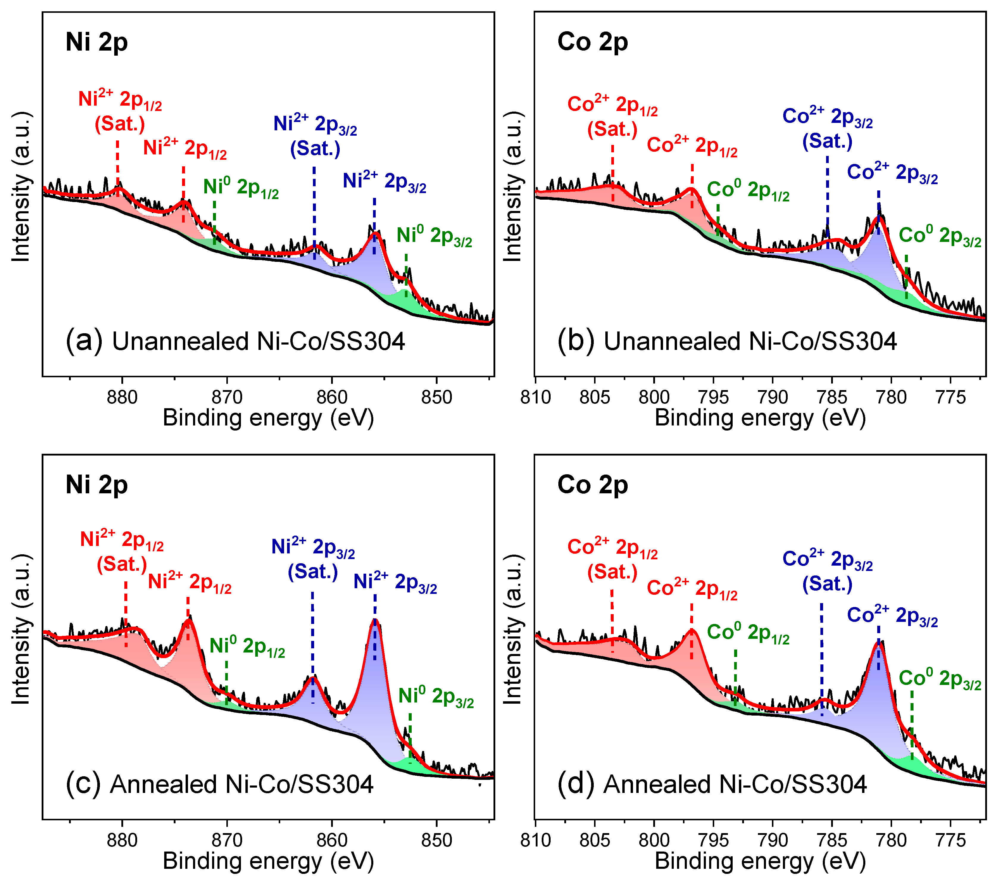
3.1. Morphology and Composition

The SEM surface morphology of SS304 samples before and after treatment is displayed in Figure 2. As shown in Figure 2a, the bare SS304 surface is flat and clean, and the textures of scratches observed on it are mainly caused by sandpaper grinding. After electrodeposition, as demonstrated in Figure 2b, the scratches on the SS304 surface disappear and are completely covered by the coating, which indicates that the coating exhibits high compactness and thickness. Meanwhile, there are many micro/nano protrusions on the coating surface. The thickness of the coating was measured to be 55.9 ± 3.1 μm, as shown in the illustration in Figure 2b. In addition, the coating grows closely with the SS304 substrate, demonstrating strong adhesion and high mechanical strength. According to the determination method of metal layer adhesion in GB/T 40262-2021, the adhesion of the prepared coating is grade 5. It is known that Liu et al. [45] prepared a series of metal surfaces with high hydrophobicity by electrodeposition, without using low surface energy substance. It had been proved that the main reason for the high hydrophobicity was the adsorption of airborne hydrocarbons, which could reduce the surface energy of metal surfaces. Meanwhile, their study revealed that the adsorption of airborne hydrocarbons on metal surfaces was almost inevitable, and the increase in ambient temperature could accelerate this process. Then, the electrodeposited SS304 surface was annealed in the oven at 60 °C to rapidly improve the surface hydrophobicity. However, the surface morphology of the sample (Figure 2c) after annealing had no obvious differences from that before annealing. High-magnification observation (Figure 2d) shows that the micro/nano convex structures grown on the coating are mostly cone-shaped or cauliflower-shaped, with different sizes, mainly in the range of 0.3~5 μm.
The EDS composition information of SS304 modified by electrodeposition before and after annealing is listed in Table 1. The surface elements of the electrodeposited sample are Ni, Co, C, and O, while the main elements are Ni and Co, and their atomic content ratio is close to 1:1, indicating that the coating prepared on the SS304 surface is a Ni–Co alloy. After annealing, the elements of the Ni–Co alloy coating are still the same, but the relative contents of C and O increase, which indicates that the oxidation degree of the Ni–Co alloy coated surface increases after treatment, and many organic substances may be adsorbed on the coating surface [43,45,54]. EDS mapping (Figure S1) also shows that the distribution of Ni and Co elements is very uniform, indicating that the Ni–Co coating is likely to be composed of a single phase. However, the surface morphology of the annealed sample does not change.
Figure 3 shows the XRD patterns of bare SS304 and Ni–Co/SS304 before and after annealing. The diffraction peaks of bare SS304 appear at 43.6, 50.8 and 74.7°, corresponding to the (111), (200) and (220) crystal planes of its austenite structure (Fe) [55]. As for the XRD patterns of the Ni–Co/SS304 samples, the diffraction peaks of the SS304 substrate cannot be observed, but new diffraction peaks appear at 44.4 and 51.9°, which are consistent with the peaks that come from the (111) and (200) crystal planes of CoNi (1/1) solid solution (ICDD-PDF 97-010-8308) with a face-centered cubic structure. The diffraction peak positions of the XRD patterns of Ni–Co/SS304 before and after annealing do not demonstrate significant differences, which indicates that the low-temperature annealing treatment does not affect the phase structure of the Ni–Co alloy coating.

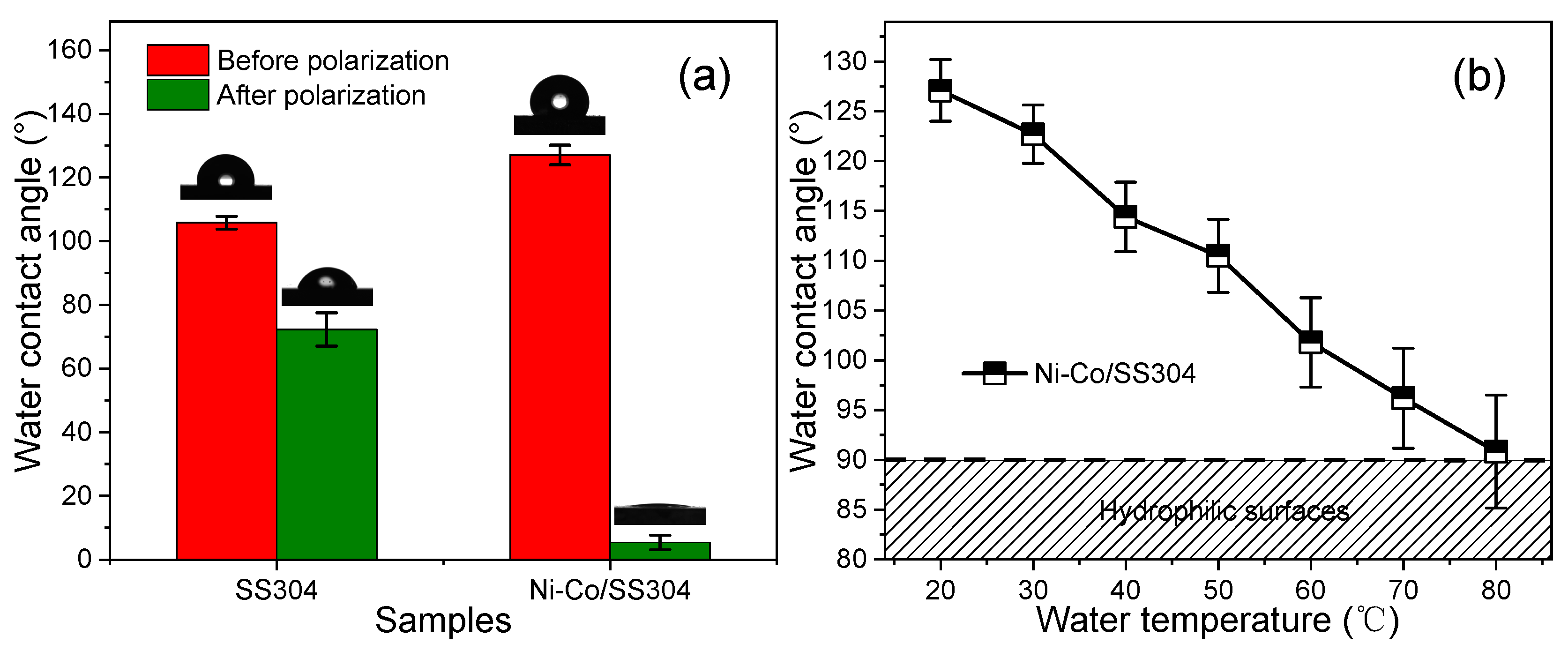
3.2. Surface Wettability of Electrodeposited Ni–Co Alloy Coatings

The surface wettability change in Ni–Co/SS304 with annealing time is shown in Figure 4. The unannealed Ni–Co/SS304 surface exhibits superhydrophilicity (WCA < 10°). With the extension of annealing time, the WCA of the Ni–Co/SS304 surface gradually increases, while the SA gradually decreases. When the annealing time is longer than 2 h, the surface of Ni–Co/SS304 becomes hydrophobic. The Ni–Co/SS304 surface needs to be annealed for more than 48 h to obtain stable WCA and SA, and the final stable WCA and SA values are about 127.1° and 43.3°, respectively. If the annealing time is extended to two weeks, the WCA and SA will still increase and decrease, respectively, but the changes are very small. After two weeks, the WCA would not exceed 135°. Considering the time cost and benefit, the hydrophobicity of the Ni–Co coating generated within two days is acceptable. In brief, the above results reveal that low-temperature annealing treatment can significantly improve the hydrophobicity of the Ni–Co/SS304 surface.
To find out the essential reason for the increase in hydrophobicity of the Ni–Co/SS304 surface caused by annealing treatment, XPS analysis was conducted (Figure 5 and Figure 6). Figure 5a,b display the XPS spectra of Ni 2p and Co 2p orbitals of the unannealed Ni–Co/SS304 surface, which can be divided into six characteristic peaks, belonging to Ni2+, Ni0, Co2+, and Co0, respectively. These peaks are related to the existence of Ni and Co elements with different valence states in NiO, CoO, and CoNi solid solutions [43]. Figure 5c,d show that after annealing treatment, the same characteristic peaks are also found in the XPS spectra of Ni 2p and Co 2p orbitals of Ni–Co/SS304, which should be derived from the same elements and valence states. However, after annealing, the relative atomic content of the surface metal state of the Ni–Co alloy coating in the total content of Ni and Co decreased from about 30.49% and 28.77% to about 11.36% and 14.20%, respectively. The above results show that annealing increases the degree of oxidation of the Ni–Co alloy coating surface. This is consistent with the result of EDS. However, due to the high degree of surface oxidation before annealing, the oxidation caused by annealing is quite limited. Therefore, it is unlikely that the significant decrease in surface wettability of the Ni–Co alloy coating is simply caused by the increase in surface oxidation degree.
According to a common theory, as also mentioned above, it is believed that the adsorption of airborne hydrocarbons (usually with low surface energy, mostly volatile organic compounds) will lead to an increase in surface hydrophobicity [43,45,56]. Therefore, as shown in Figure 6, the XPS spectra of the C 1s and O 1s orbitals of the Ni–Co alloy coating were further analyzed. According to the XPS spectra of the C 1s orbital in Figure 6a,c, the characteristic peaks of unannealed Ni–Co/SS304 at 286 eV (C-O-C) and 288.7 eV (O-C=O) are relatively low, while these characteristic peaks are significantly enhanced after the Ni–Co alloy coating is annealed, indicating that only a small amount of organic matter may be attached to the Ni–Co alloy coating surface before annealing, and more organics are adsorbed on the surface after the annealing treatment [43]. As shown in Figure 6b,d, the characteristic peak of C=O in the O 1s orbital of the Ni–Co alloy coating after annealing is also enhanced compared with that before annealing, which also confirms the increase in organic adsorption on the surface. In addition, after annealing, the characteristic peaks of metal oxides at 529~530 eV in Figure 6d rise notably, which is also strong evidence for the increase in oxidation degree on the Ni–Co alloy coating surface [57]. The above results reveal that the transition of the Ni–Co alloy coating from hydrophilicity to hydrophobicity is caused by the adsorption of airborne hydrocarbons. This is of great guiding significance to the improvement of the hydrophobicity of SS304 bipolar plates by surface modification.

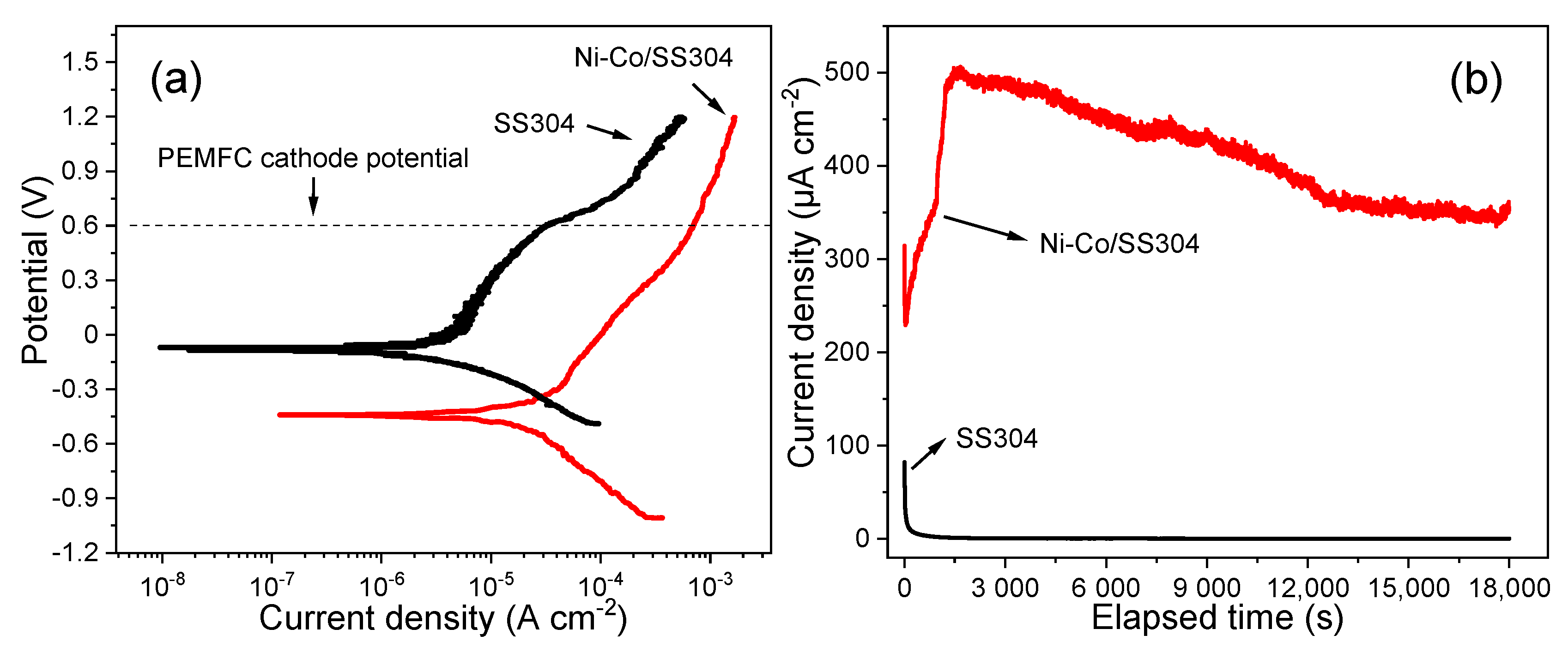
3.3. Corrosion Behavior of Ni–Co/SS304 in the Simulated PEMFC Cathodic Environment

The corrosion behavior of Ni–Co/SS304 (which hereafter refers to the annealed sample) in the simulated PEMFC cathodic environment was investigated by potentiodynamic and potentiostatic polarizations. As shown in Figure 7a, the cathodic polarization curves of bare SS304 and Ni–Co/SS304 exhibit similar behaviors. However, at the same potential, the current density of Ni–Co/SS304 is lower than that of bare SS304, indicating that the cathodic reaction of SS304 is inhibited after being modified by the Ni–Co alloy coating. Meanwhile, the anodic polarization behaviors of bare SS304 and Ni–Co/SS304 are also similar with a few differences. The active-passive transition process is not observed in the two anodic polarization curves, which is related to their spontaneous passivation behavior in the simulated PEMFC solution. With the polarization potential rising, the anodic current densities of the two samples increase slowly and proportionally, and the polarizability gradually increases, which may be caused by the dynamic dissolution and growth process of the surface passive film. When it reaches a certain potential, the current density of bare SS304 increases rapidly, which indicates that the passive film begins to breakdown, and the corresponding potential is breakdown potential (Eb). However, the current density of Ni–Co/SS304 still increases approximately linearly, and there is no obvious passive-transpassive transition process. Above −0.3 V, although the anode current density of Ni–Co/SS304 increases slowly, it is much higher than that of bare SS304. The above anodic polarization behavior of Ni–Co/SS304 is usually called pseudo-passivation [58].
Table 2 lists the polarization parameters of the potentiodynamic polarization curves of bare SS304 and Ni–Co/SS304. Ni–Co/SS304 demonstrates lower corrosion potential and higher corrosion current density compared with bare SS304, which indicates that the corrosion resistance of Ni–Co/SS304 is lower than that of the bare substrate, showing higher corrosion tendency. Meanwhile, at the typical cathode working potential of PEMFC (0.6 V vs. SCE), both bare SS304 and Ni–Co/SS304 are in corrosion state, but the current density of Ni–Co/SS304 is much higher than that of bare SS304.
Then, 5 h potentiostatic polarization (0.6 V vs. SCE) was conducted to simulate the long-term PEMFC working condition. As shown in Figure 7b, the current density of both bare SS304 and Ni–Co/SS304 decreases rapidly with time in the initial stage, which may be related to the rapid passivation of the surface of SS304, and the oxide film formed on the surface of the Ni–Co alloy coating before polarization. As the polarization continues, the current density of bare SS304 is still decreasing gradually and slowly, while the current density of Ni–Co/SS304 begins to increase rapidly, and it reaches a maximum value of about 500 μA/cm2 after 1700 s. Then, as the polarization time increases, the current density of Ni–Co/SS304 begins to decrease steadily and finally stabilizes at about 350 μA/cm2, which is larger than the final stable current density of bare SS304 (0.291 μA/cm2). The increase in the current density of Ni–Co/SS304 is related to the damage of the protective film formed on the surface before polarization, while the decrease in the current density is associated with the formation of the new oxide film. The above results show that in the simulated PEMFC cathodic environment, the oxide film formed on the Ni–Co/SS304 surface can inhibit further corrosion, but the corrosion resistance is lower than that of the SS304 substrate.

3.4. Surface Properties of Ni–Co/SS304 in the Simulated PEMFC Cathodic Environment

The surface morphology, composition, wettability, and conductivity were characterized to further explore the surface property changes in Ni–Co/SS304 in the simulated PEMFC cathodic environment. The SEM images of the Ni–Co/SS304 surface after potentiostatic polarization (0.6 V, 5 h) are shown in Figure 8, and the sample surface shows obvious local corrosion. A large area of corrosion product (dark part) appears on the surface of polarized Ni–Co/SS304, while the cauliflower-shaped micro/nano structures still exist. At high magnification (Figure 8b), the observed surface morphology of the polarized sample has no obvious change compared with that before polarization in the area, where there is no corrosion product accumulation. However, in the dark area, the micro/nano structures of the polarized Ni–Co/SS304 surface are almost completely covered by corrosion products, showing masked morphology. In addition, many cracks also appeared in these areas, which may be related to the composition characteristics of the corrosion products.
Figure 8c,d show the EDS spectra of the two different regions on polarized Ni–Co/SS304, and the detailed compositions are listed in Table 3. The area without corrosion product accumulation (area 1) mainly contains Ni, Co, C, and O. Compared with the polarized Ni–Co/SS304 surface, in area 1, the relative content of Ni increases slightly, while the content of Co and C decreases. The content of C has been reduced to close to that before annealing treatment, but the content of O changes little. As shown in Figure 8d and Table 3, the area with corrosion product accumulation (area 2) contains Ni, Co, C, O, and S. In area 2, the relative content ratio of Ni/Co is similar to that of area 1, and the content of C is much lower, while the content of O is extremely high, and a small amount of S appears. The composition difference reveals that the corrosion rate of alloying elements in the Ni–Co alloy coating in these two areas is similar, and the Co dissolves preferentially. The hydrocarbons adsorbed on the Ni–Co/SS304 surface have been separated from the surface after polarization, which may lead to the increase in surface wettability.
The XPS analysis was carried out to further understand the chemical composition of the oxide film formed on the surface after polarization and the types of possible corrosion products. As displayed in Figure 9, the XPS spectrum of the Ni 2p orbit of polarized Ni–Co/SS304 mainly shows the characteristic peaks of Ni2+ in NiO, while the component of metallic Ni disappears compared with that before polarization. In contrast, the component of the Co 2p spectrum of the polarized sample is very complicated, among which the split spin-orbit components of Co0, Co2+, and Co3+ can be found. The Co LMM Auger peak and the corresponding Co 2p split spin-orbit components represent the presence of metal Co on the surface, while the satellite features owing to 2+ and 3+ states of Co can sufficiently prove the existence of CoO and Co3O4. The characteristic peaks of C–O–C and O–C=O in the C 1s spectrum are reduced, which is equivalent to that of the sample before annealing. As for the S 2p spectrum, the closely spaced spin-orbit components at 168.77 and 169.93 eV belong to metal sulfates. The results reveal that the oxides and corrosion products formed on the surface are mainly NiO, CoO, Co3O4, and sulfates of Ni or Co. The corrosion resistance of the Ni–Co alloy coating is closely related to the formation of oxides of NiO, CoO, and Co3O4, which will further react with sulfuric acid in the simulated PEMFC solution at 0.6 V to form the corresponding sulfates. However, the appearance of metal Co indicates that the corrosion resistance of Co oxides is not as good as that of Ni oxides, and they are more likely to react with sulfuric acid or dissolve in the solution, which will lead to the exposure of metal components. Besides, the weakening of the peaks of C 1s components confirms the reduction in hydrocarbons adsorbed on the surface. Typically, the above chemical composition changes could lead to a significant increase in surface wettability, which will be verified by the wettability characterization.
Figure 10a shows the WCA of bare SS304 and Ni–Co/SS304 surfaces before and after potentiostatic polarization (0.6 V, 5 h). The bare SS304 surface is hydrophobic (WCA = 106.2 ± 1.8°) and becomes hydrophilic (WCA = 71.8 ± 5.6°) after polarization. After electrodeposition of the Ni–Co alloy coating, the WCA of the Ni–Co/SS304 surface can be increased to 127.1 ± 3.1°. However, as predicted by the EDS and XPS results, its surface wettability also increases sharply and becomes superhydrophilic (WCA = 5.4 ± 2.3°) with polarization (0.6 V, 5 h), which is most likely caused by the desorption of surface hydrocarbons and the generation of hydrophilic corrosion products. As discussed, the increase in hydrophobicity of the Ni–Co/SS304 surface is mainly caused by the attachment of hydrocarbons. In addition, the working environment temperature of PEMFC is usually around 80 °C, so the hot water repellency of the bipolar plates is also very important. Figure 10b demonstrates the WCA of the Ni–Co/SS304 surface under water droplets at different temperatures. With the increase in water temperature, the WCA of the Ni–Co/SS304 surface decreases gradually, but when the water droplet temperature reaches 80 °C, its WCA is still greater than 90°. The above changes in WCA reveal that the electrodeposited Ni–Co alloy coating can improve the hydrophobicity of the bare SS304 surface, and even in the high-temperature PEMFC environment, the surface of Ni–Co/SS304 is still hydrophobic. Nevertheless, its hydrophobicity is still unstable and will be reduced by polarization, in a similar way to the SS304 substrate.
Figure 11 shows the ICR of bare SS304 and Ni–Co/SS304 surfaces before and after potentiostatic polarization (0.6 V, 5 h). The ICR values of all samples gradually decrease with the increase in the applied compression pressure. At the typical stacking compression pressure of 150 N/cm2 for bipolar plates, the ICR of polarized samples is much larger than that before polarization, which may be due to the formation of oxide films with poor conductivity on the surface after polarization. Meanwhile, the ICR values of SS304 before and after polarization are larger than that of the corresponding Ni–Co/SS304, which manifests that the surface conductivity of the electrodeposited Ni–Co alloy coating is better than that of the SS304 substrate. This may be attributed to the formation of more nickel oxides on the surface of Ni–Co alloy coating, and the ICR of nickel oxides is much lower than that of iron and chromium oxides formed on the SS304 substrate, as proved by the literature [30,31].

4. Conclusions

In summary, a Ni–Co alloy coating with cauliflower-shaped micro/nano structures was prepared on the SS304 surface by galvanostatic deposition to improve the performance of SS304 bipolar plates in the PEMFC environment. The main composition of the electrodeposited Ni–Co alloy coating was a CoNi (1/1) solid solution with a face-centered cubic structure, and the Ni–Co/SS304 exhibited high hydrophobicity after annealing, of which the origin of the increased hydrophobicity was related to the surface adsorption of airborne hydrocarbons. Meanwhile, the Ni–Co/SS304 could also maintain the hydrophobic state under the hot-water droplet up to 80 °C. In the simulated PEMFC cathodic environment, although the corrosion resistance of Ni–Co/SS304 was not as good as that of the SS304 substrate, the formation of a surface oxide film could still inhibit corrosion. The surface wettability of Ni–Co/SS304 increases in a similar way to the bare SS304 after potentiostatic polarization (0.6 V, 5 h), which was associated with the formation of hydrophilic oxides and needed special attention. In addition, the ICR values of Ni–Co/SS304 before and after potentiostatic polarization were lower than that of the bare SS304 substrate, showing better conductivity. Generally speaking, the electrodeposited Ni–Co alloy coating with cauliflower-shaped micro/nano structures can improve the hydrophobicity and surface conductivity of the SS304 substrate as bipolar plates. This research provides a new idea for improving the surface hydrophobicity of bipolar plates and lays a good theoretical basis for preparing high performance stainless-steel bipolar plates by electrodeposition modification.

Supplementary Materials

The following supporting information can be downloaded at: https://0-www-mdpi-com.brum.beds.ac.uk/article/10.3390/nano12121976/s1, Figure S1: EDS mapping of the surface elements of the cauliflower-shaped structure on the electrodeposited Ni–Co coating.

Author Contributions

Conceptualization, methodology, writing—original draft preparation, J.X.; writing—review and editing, L.X. (Likun Xu) and Y.L.; supervision, L.X. (Likun Xu), Y.X., L.X. (Lili Xue) and L.L.; funding acquisition, L.X. (Likun Xu) and Y.X. All authors have read and agreed to the published version of the manuscript.

Funding

This research received no external funding.

Institutional Review Board Statement

Not applicable.

Informed Consent Statement

Not applicable.

Data Availability Statement

The data that support the results of this study are available from the corresponding author upon reasonable request.

Acknowledgments

This work was supported by the Luoyang Ship Material Research Institute.

Conflicts of Interest

The authors declare no conflict of interest.

References

  1. Dunn, S. Hydrogen futures: Toward a sustainable energy system. Int. J. Hydrogen Energy 2002, 27, 235–264. [Google Scholar] [CrossRef]
  2. Momirlan, M.; Veziroglu, T. Current status of hydrogen energy. Renew. Sustain. Energy Rev. 2002, 6, 141–179. [Google Scholar] [CrossRef]
  3. Mehta, V.; Cooper, J.S. Review and analysis of PEM fuel cell design and manufacturing. J. Power Sources 2003, 114, 32–53. [Google Scholar] [CrossRef]
  4. Yang, Y.; Guo, L.J.; Liu, H.T. Corrosion characteristics of SS316L as bipolar plate material in PEMFC cathode environments with different acidities. Int. J. Hydrogen Energy 2011, 36, 1654–1663. [Google Scholar] [CrossRef]
  5. Kandlikar, S.G.; Lu, Z.J. Thermal management issues in a PEMFC stack-A brief review of current status. Appl. Therm. Eng. 2009, 29, 1276–1280. [Google Scholar] [CrossRef]
  6. Weil, K.S.; Xia, G.; Yang, Z.G.; Kim, J.Y. Development of a niobium clad PEM fuel cell bipolar plate material. Int. J. Hydrogen Energy 2007, 32, 3724–3733. [Google Scholar] [CrossRef]
  7. Yoon, W.; Huang, X.Y.; Fazzino, P.; Reifsnider, K.L.; Akkaoui, M.A. Evaluation of coated metallic bipolar plates for polymer electrolyte membrane fuel cells. J. Power Sources 2008, 179, 265–273. [Google Scholar] [CrossRef]
  8. Feng, K.; Wu, G.S.; Li, Z.G.; Cai, X.; Chu, P.K. Corrosion behavior of SS316L in simulated and accelerated PEMFC environments. Int. J. Hydrogen Energy 2011, 36, 13032–13042. [Google Scholar] [CrossRef]
  9. Davies, D.P.; Adcock, P.L.; Turpin, M.; Rowen, S.J. Stainless steel as a bipolar plate material for solid polymer fuel cells. J. Power Sources 2000, 86, 237–242. [Google Scholar] [CrossRef]
  10. Makkus, R.C.; Janssen, A.H.H.; de Bruijn, F.A.; Mallant, R.K.A.M. Use of stainless steel for cost competitive bipolar plates in the SPFC. J. Power Sources 2000, 86, 274–282. [Google Scholar] [CrossRef]
  11. Li, X.G.; Sabir, M. Review of bipolar plates in PEM fuel cells: Flow-field designs. Int. J. Hydrogen Energy 2005, 30, 359–371. [Google Scholar] [CrossRef]
  12. Nowak, A.P.; Salguero, T.T.; Kirby, K.W.; Zhong, F.; Blunk, R.H.J. A conductive and hydrophilic bipolar plate coating for enhanced proton exchange membrane fuel cell performance and water management. J. Power Sources 2012, 210, 138–145. [Google Scholar] [CrossRef]
  13. Cunningham, B.D.; Huang, J.; Baird, D.G. Review of materials and processing methods used in the production of bipolar plates for fuel cells. Int. Mater. Rev. 2007, 52, 1–13. [Google Scholar] [CrossRef]
  14. Hermann, A.; Chaudhuri, T.; Spagnol, P. Bipolar plates for PEM fuel cells: A review. Int. J. Hydrogen Energy 2005, 30, 1297–1302. [Google Scholar] [CrossRef]
  15. Wang, H.; Turner, J.A. Reviewing metallic PEMFC bipolar plates. Fuel Cells 2010, 10, 510–519. [Google Scholar] [CrossRef]
  16. Tawfik, H.; Hung, Y.; Mahajan, D. Metal bipolar plates for PEM fuel cell-A review. J. Power Sources 2007, 163, 755–767. [Google Scholar] [CrossRef]
  17. Karimi, S.; Fraser, N.; Roberts, B.; Foulkes, F.R. A review of metallic bipolar plates for proton exchange membrane fuel cells: Materials and fabrication methods. Adv. Mater. Sci. Eng. 2012, 2012, 828070. [Google Scholar] [CrossRef] [Green Version]
  18. Olayinka, A.; Emblom, W.J. Surface roughness of AISI 1010 and AISI 304 of PEMFC bipolar plates with microscale hydroformed capillary channels. Proc. Inst. Mech. Eng. Part B 2022, 09544054221077772. [Google Scholar] [CrossRef]
  19. Jin, C.K.; Lee, K.H.; Kang, C.G. Performance and characteristics of titanium nitride, chromium nitride, multi-coated stainless steel 304 bipolar plates fabricated through a rubber forming process. Int. J. Hydrogen Energy 2015, 40, 6681–6688. [Google Scholar] [CrossRef]
  20. Chen, M.; Ding, J.C.; Kwon, S.-H.; Wang, Q.; Zhang, S. Corrosion resistance and conductivity of NbN-coated 316L stainless steel bipolar plates for proton exchange membrane fuel cells. Corros. Sci. 2022, 196, 110042. [Google Scholar] [CrossRef]
  21. Forouzanmehr, M.; Kashyzadeh, K.R.; Borjali, A.; Ivanov, A.; Jafarnode, M.; Gan, T.H.; Wang, B.; Chizari, M. Detection and analysis of corrosion and contact resistance faults of TiN and CrN coatings on 410 stainless steel as bipolar plates in PEM fuel cells. Sensors 2022, 22, 750. [Google Scholar] [CrossRef] [PubMed]
  22. Maistro, G.; Kante, S.; Nyborg, L.; Cao, Y. Low-temperature carburized high-alloyed austenitic stainless steels in PEMFC cathodic environment. Surf. Interfaces 2021, 24, 101093. [Google Scholar] [CrossRef]
  23. Myung, S.T.; Kumagai, M.; Asaishi, R.; Sun, Y.K.; Yashiro, H. Nanoparticle TiN-coated type 310S stainless steel as bipolar plates for polymer electrolyte membrane fuel cell. Electrochem. Commun. 2008, 10, 480–484. [Google Scholar] [CrossRef]
  24. Lv, J.L.; Wang, Z.Q.; Liang, T.X.; Ken, S.; Hideo, M. Enhancing the corrosion resistance of the 2205 duplex stainless steel bipolar plates in PEMFCs environment by surface enriched molybdenum. Results Phys. 2017, 7, 3459–3464. [Google Scholar]
  25. Wang, L.; Li, L.; Liu, H.; Wang, S.; Fang, H.; Gao, H.; Gao, K.; Zhang, Y.; Sun, J.; Yan, J. Polylaminate TaN/Ta coating modified ferritic stainless steel bipolar plate for high temperature proton exchange membrane fuel cell. J. Power Sources 2018, 399, 343–349. [Google Scholar] [CrossRef]
  26. Fukutsuka, T.; Yamaguchi, T.; Miyano, S.I.; Matsuo, Y.; Sugie, Y.; Ogumi, Z. Carbon-coated stainless steel as PEFC bipolar plate material. J. Power Sources 2007, 174, 199–205. [Google Scholar] [CrossRef]
  27. Wang, L.X.; Sun, J.C.; Li, P.B.; Jing, B.; Li, S.; Wen, Z.S.; Ji, S.J. Niobized AISI 304 stainless steel bipolar plate for proton exchange membrane fuel cell. J. Power Sources 2012, 208, 397–403. [Google Scholar] [CrossRef]
  28. Kim, K.M.; Kim, J.H.; Lee, Y.Y.; Kim, K.Y. Electrodeposition of ruthenium oxide on ferritic stainless steel bipolar plate for polymer electrolyte membrane fuel cells. Int. J. Hydrogen Energy 2012, 37, 1653–1660. [Google Scholar] [CrossRef]
  29. Garcia, M.A.L.; Smit, M.A. Study of electrodeposited polypyrrole coatings for the corrosion protection of stainless steel bipolar plates for the PEM fuel cell. J. Power Sources 2006, 158, 397–402. [Google Scholar] [CrossRef]
  30. Feng, K.; Shen, Y.; Mai, J.M.; Liu, D.A.; Cai, X. An investigation into nickel implanted 316L stainless steel as a bipolar plate for PEM fuel cell. J. Power Sources 2008, 182, 145–152. [Google Scholar] [CrossRef]
  31. Feng, K.; Shen, Y.; Liu, D.A.; Chu, P.K.; Cai, X. Ni-Cr Co-implanted 316L stainless steel as bipolar plate in polymer electrolyte membrane fuel cells. Int. J. Hydrogen Energy 2010, 35, 690–700. [Google Scholar] [CrossRef]
  32. Loto, C.A. Electroless nickel plating-A review. Silicon 2016, 8, 177–186. [Google Scholar] [CrossRef]
  33. Kim, S.; Yamaura, S.; Makino, A.; Inoue, A. Production of Ni-P amorphous alloy-coated bipolar plate for PEM fuel cell by electro-less plating. Mater. Trans. 2011, 52, 709–713. [Google Scholar] [CrossRef] [Green Version]
  34. Fetohi, A.E.; Hameed, R.M.A.; El-Khatib, K.M. Ni-P and Ni-Mo-P modified aluminium alloy 6061 as bipolar plate material for proton exchange membrane fuel cells. J. Power Sources 2013, 240, 589–597. [Google Scholar] [CrossRef]
  35. Fetohi, A.E.; Hameed, R.M.A.; El-Khatib, K.M.; Souaya, E.R. Ni-P and Ni-Co-P coated aluminum alloy 5251 substrates as metallic bipolar plates for PEM fuel cell applications. Int. J. Hydrogen Energy 2012, 37, 7677–7688. [Google Scholar] [CrossRef]
  36. Fetohi, A.E.; Hameed, R.M.A.; El-Khatib, K.M.; Souaya, E.R. Study of different aluminum alloy substrates coated with Ni-Co-P as metallic bipolar plates for PEM fuel cell applications. Int. J. Hydrogen Energy 2012, 37, 10807–10817. [Google Scholar] [CrossRef]
  37. Tsai, S.Y.; Bai, C.Y.; Lin, C.H.; Shi, G.N.; Hou, K.H.; Liu, Y.M.; Ger, M.D. The characteristics and performance of electroless nickel and immersion Au plated aluminum alloy bipolar plates in polymer electrolyte membrane fuel cells. J. Power Sources 2012, 214, 51–58. [Google Scholar] [CrossRef]
  38. Tsai, S.Y.; Lin, C.H.; Jian, Y.J.; Hou, K.H.; Ger, M.D. The fabrication and characteristics of electroless nickel and immersion Au-polytetrafluoroethylene composite coating on aluminum alloy 5052 as bipolar plate. Surf. Coat. Technol. 2017, 313, 151–157. [Google Scholar] [CrossRef]
  39. Darband, G.B.; Aliofkhazraei, M.; Rouhaghdam, A.S.; Kiani, M.A. Three-dimensional Ni-Co alloy hierarchical nanostructure as efficient non-noble-metal electrocatalyst for hydrogen evolution reaction. Appl. Surf. Sci. 2019, 465, 846–862. [Google Scholar] [CrossRef]
  40. Khorsand, S.; Raeissi, K.; Ashrafizadeh, F.; Arenas, M.A. Relationship between the structure and water repellency of nickel-cobalt alloy coatings prepared by electrodeposition process. Surf. Coat. Technol. 2015, 276, 296–304. [Google Scholar] [CrossRef]
  41. Bakhit, B.; Akbari, A. Nanocrystalline Ni-Co alloy coatings: Electrodeposition using horizontal electrodes and corrosion resistance. J. Coat. Technol. Res. 2013, 10, 285–295. [Google Scholar] [CrossRef]
  42. Rashtchi, H.; Raeissi, K.; Shamanian, M.; Gomez, Y.A.; Lagergren, C.; Lindstrom, R.W.; Rajaei, V. Evaluation of Ni-Mo and Ni-Mo-P electroplated coatings on stainless steel for PEM fuel cells bipolar plates. Fuel Cells 2016, 16, 784–800. [Google Scholar] [CrossRef]
  43. Khorsand, S.; Raeissi, K.; Ashrafizadeh, F.; Arenas, M.A. Super-hydrophobic nickel-cobalt alloy coating with micro-nano flower-like structure. Chem. Eng. J. 2015, 273, 638–646. [Google Scholar] [CrossRef] [Green Version]
  44. Li, X.M.; Reinhoudt, D.; Crego-Calama, M. What do we need for a superhydrophobic surface? A review on the recent progress in the preparation of superhydrophobic surfaces. Chem. Soc. Rev. 2007, 36, 1350–1368. [Google Scholar] [CrossRef] [PubMed]
  45. Liu, P.; Cao, L.; Zhao, W.; Xia, Y.; Huang, W.; Li, Z. Insights into the superhydrophobicity of metallic surfaces prepared by electrodeposition involving spontaneous adsorption of airborne hydrocarbons. Appl. Surf. Sci. 2015, 324, 576–583. [Google Scholar] [CrossRef]
  46. Zhang, W. Research on the Preparation and Corrosion Resistance of Ni-Co Based Composite Coating on Carbon Steel Surface. Master’s Thesis, Ocean University of China, Qingdao, China, 2019. [Google Scholar]
  47. Lin, Z.F.; Zhang, W.; Xu, L.K.; Xue, Y.P.; Li, W.H. Fabrication of Ni-Co/Cu super-hydrophobic coating with improved corrosion resistance. Mater. Chem. Phys. 2022, 277, 125503. [Google Scholar] [CrossRef]
  48. Kumar, A.; Ricketts, M.; Hirano, S. Ex situ evaluation of nanometer range gold coating on stainless steel substrate for automotive polymer electrolyte membrane fuel cell bipolar plate. J. Power Sources 2010, 195, 1401–1407. [Google Scholar] [CrossRef]
  49. Wang, H.L.; Sweikart, M.A.; Turner, J.A. Stainless steel as bipolar plate material for polymer electrolyte membrane fuel cells. J. Power Sources 2003, 115, 243–251. [Google Scholar] [CrossRef]
  50. Xuan, J.J.; Xu, L.K.; Bai, S.F.; Zhao, T.; Xin, Y.L.; Zhang, G.D.; Xue, L.L.; Li, L. Influence of temperature on corrosion behavior, wettability, and surface conductivity of 304 stainless steel in simulated cathode environment of proton exchange membrane fuel cells. Int. J. Hydrogen Energy 2021, 46, 22920–22931. [Google Scholar] [CrossRef]
  51. Yang, Y.; Guo, L.J.; Liu, H.T. The effect of temperature on corrosion behavior of SS316L in the cathode environment of proton exchange membrane fuel cells. J. Power Sources 2011, 196, 5503–5510. [Google Scholar] [CrossRef]
  52. Yang, Y.; Guo, L.J.; Liu, H.T. Factors affecting corrosion behavior of SS316L as bipolar plate material in PEMFC cathode environments. Int. J. Hydrogen Energy 2012, 37, 13822–13828. [Google Scholar] [CrossRef]
  53. Li, D.G.; Wang, J.D.; Chen, D.R.; Liang, P. Influences of pH value, temperature, chloride ions and sulfide ions on the corrosion behaviors of 316L stainless steel in the simulated cathodic environment of proton exchange membrane fuel cell. J. Power Sources 2014, 272, 448–456. [Google Scholar] [CrossRef]
  54. Xu, P.; Wang, F.; Yang, C.; Ou, J.; Li, W.; Amirfazli, A. Reversible transition between superhydrophobicity and superhydrophilicity of a silver surface. Surf. Coat. Technol. 2016, 294, 47–53. [Google Scholar] [CrossRef]
  55. Dadfar, M.; Salehi, M.; Golozar, M.A.; Trasatti, S. Surface modification of 304 stainless steels to improve corrosion behavior and interfacial contact resistance of bipolar plates. Int. J. Hydrogen Energy 2016, 41, 21375–21384. [Google Scholar] [CrossRef]
  56. Rahimi, E.; Rafsanjani-Abbasi, A.; Kiani-Rashid, A.; Jafari, H.; Davoodi, A. Morphology modification of electrodeposited superhydrophobic nickel coating for enhanced corrosion performance studied by AFM, SEM-EDS and electrochemical measurements. Colloids Surf. A 2018, 547, 81–94. [Google Scholar] [CrossRef]
  57. Shen, L.; Fan, M.; Qiu, M.; Jiang, W.; Wang, Z. Superhydrophobic nickel coating fabricated by scanning electrodeposition. Appl. Surf. Sci. 2019, 483, 706–712. [Google Scholar] [CrossRef]
  58. Wang, Z.; Feng, Z.; Fan, X.H.; Zhang, L. Pseudo-passivation mechanism of CoCrFeNiMo0.01 high-entropy alloy in H2S-containing acid solutions. Corros. Sci. 2021, 179, 109146. [Google Scholar] [CrossRef]
Figure 1. Schematic diagrams of the device and principle of electrodeposition of Ni–Co coating.
Nanomaterials 12 01976 g001
Figure 2. SEM surface morphology of different surfaces: (a) bare SS304; (b) unannealed Ni–Co/SS304, and the illustration in (b) is the cross-section of Ni–Co coating photographed by a 3D measuring laser microscope; (c,d) annealed Ni–Co/SS304.
Nanomaterials 12 01976 g002
Figure 3. XRD patterns of bare SS304, unannealed Ni–Co/SS304, and annealed Ni–Co/SS304.
Nanomaterials 12 01976 g003
Figure 4. WCA and SA changes in Ni–Co/SS304 surface with annealing time.
Nanomaterials 12 01976 g004
Figure 5. XPS spectra of Ni 2p and Co 2p of Ni–Co/SS304: (a,b) unannealed; (c,d) annealed.
Nanomaterials 12 01976 g005
Figure 6. XPS spectra of C 1s and O 1s of Ni–Co/SS304: (a,b) unannealed; (c,d) annealed.
Nanomaterials 12 01976 g006
Figure 7. The polarization curves of SS304 and Ni–Co/SS304 in the simulated PEMFC cathodic environment: (a) potentiodynamic polarization curves, (b) potentiostatic polarization curves (0.6 V, 5 h).
Nanomaterials 12 01976 g007
Figure 8. The SEM surface morphology at low (a) and high (b) magnification and EDS spectra of area 1 (c) and area 2 (d) with different morphologies of Ni–Co/SS304 after polarization (0.6 V, 5 h) in the simulated PEMFC cathodic environment.
Nanomaterials 12 01976 g008
Figure 9. XPS spectra of Ni 2p, Co 2p, C 1s, and O 1s of Ni–Co/SS304 after polarization (0.6 V, 5 h) in the simulated PEMFC cathodic environment.
Nanomaterials 12 01976 g009aNanomaterials 12 01976 g009b
Figure 10. (a) WCAs of bare SS304 and Ni–Co/SS304 surfaces before and after polarization (0.6 V, 5 h); (b) WCAs of Ni–Co/SS304 surface under water droplets at different temperatures.
Nanomaterials 12 01976 g010
Figure 11. The interfacial contact resistance of SS304 and Ni–Co/SS304 before (untreated) and after polarization (0.6 V, 5 h) in the simulated PEMFC cathode environment: (a) ICR at various compression forces; (b) ICR at 150 N/cm2.
Nanomaterials 12 01976 g011
Table 1. Elements and contents (at.%) of Ni–Co/SS304 surface before and after annealing obtained by EDS.
SamplesNiCoCO
Unannealed Ni–Co/SS30450.3243.872.962.85
Annealed Ni–Co/SS30449.3942.853.714.05
Table 2. Polarization parameters derived from potentiodynamic polarization curves of SS304 and Ni–Co/SS304 shown in Figure 7a.
SamplesEcorr
(V vs. SCE)
Eb
(V vs. SCE)
icorr
(μA/cm2)
i0.6 V vs. SCE
(μA/cm2)
SS304−0.07020.60084.39532.27
Ni–Co/SS304−0.4413-13.81703.3
Table 3. Elements and contents (at.%) of area 1 and area 2 with different morphologies on polarized Ni–Co/SS304 in Figure 8.
Polarized Ni–Co/SS304NiCoCO
Area 151.2742.152.603.97
Area 234.1228.251.3833.64
Publisher’s Note: MDPI stays neutral with regard to jurisdictional claims in published maps and institutional affiliations.

