
Self-Assembled Synthesis of Porous Iron-Doped Graphitic Carbon Nitride Nanostructures for Efficient Photocatalytic Hydrogen Evolution and Nitrogen Fixation


Abstract
:1. Introduction
2. Materials and Methods
2.1. Chemicals
2.1.1. Synthesis of Pure g-C3N4 (MCN)
2.1.2. Synthesis of Fe-MCNC with Supramolecular Approach
2.2. Photocatalytic Hydrogen Evolution
2.3. Photocatalytic Nitrogen Fixation Experiments
2.4. Electrochemical Analysis
2.5. Characterization
3. Results and Discussion
4. Conclusions
Author Contributions
Funding
Data Availability Statement
Acknowledgments
Conflicts of Interest
References
- Wang, X.; Maeda, K.; Thomas, A.; Takanabe, K.; Xin, G.; Carlsson, J.M.; Domen, K.; Antonietti, M. A metal-free polymeric photocatalyst for hydrogen production from water under visible light. Nat. Mater. 2009, 8, 76–80. [Google Scholar] [CrossRef] [PubMed]
- Wang, C.; Xie, J.; Chen, N.; Chen, W.; Bai, P.; Wang, H. Non-Noble-metal catalyst of Cu/g-C3N4 for efficient photocatalytic hydrogen evolution. ACS Appl. Energy Mater. 2021, 4, 13796–13802. [Google Scholar] [CrossRef]
- Rawool, S.A.; Samanta, A.; Ajithkumar, T.G.; Kar, Y.; Polshettiwar, V. Photocatalytic hydrogen generation and CO2 conversion using g-C3N4 decorated dendritic fibrous n nanosilica: Role of interfaces between silica and g-C3N4. ACS Appl. Energy Mater. 2020, 3, 8150–8158. [Google Scholar] [CrossRef]
- Zuo, S.; Zhang, H.; Li, X.; Han, C.; Yao, C.; Ni, C. Dual active sites boosting photocatalytic nitrogen fixation over upconversion mineral nanocomposites under the full spectrum. ACS Sustain. Chem. Eng. 2022, 10, 1440–1450. [Google Scholar] [CrossRef]
- Xie, H.; Zheng, Y.; Guo, X.; Liu, Y.; Zhang, Z.; Zhao, J.; Zhang, W.; Wang, Y.; Huang, Y. Rapid microwave synthesis of mesoporous oxygen-doped g-C3N4 with carbon vacancies for efficient photocatalytic H2O2 production. ACS Sustain. Chem. Eng. 2021, 9, 6788–6798. [Google Scholar] [CrossRef]
- Zhao, L.; Guo, L.; Tang, Y.; Zhou, J.; Shi, B. Novel g-C3N4/C/Fe2O3 composite for efficient photocatalytic reduction of aqueous Cr(VI) under light irradiation. Ind. Eng. Chem. Res. 2021, 60, 13594–13603. [Google Scholar] [CrossRef]
- Xu, H.; Yi, J.; She, X.; Liu, Q.; Song, L.; Chen, S.; Yang, Y.; Song, Y.; Vajtai, R.; Lou, J. 2D heterostructure comprised of metallic 1T-MoS2/monolayer O-g-C3N4 towards efficient photocatalytic hydrogen evolution. Appl. Catal. B Environ. 2018, 220, 379–385. [Google Scholar] [CrossRef]
- Zhu, Y.-P.; Ren, T.-Z.; Yuan, Z.-Y. Mesoporous phosphorus-doped g-C3N4 nanostructured flowers with superior photocatalytic hydrogen evolution performance. ACS Appl. Mater. Interfaces 2015, 7, 16850–16856. [Google Scholar] [CrossRef]
- Vu, M.-H.; Sakar, M.; Nguyen, C.-C.; Do, T.-O. Chemically bonded Ni cocatalyst onto the S doped g-C3N4 nanosheets and their synergistic enhancement in H2 production under sunlight irradiation. ACS Sustain. Chem. Eng. 2018, 6, 4194–4203. [Google Scholar] [CrossRef]
- Shwetharani, R.; Kapse, S.; Thapa, R.; Nagaraju, D.H.; Balakrishna, R.G. Dendritic ferroselite (FeSe2) with 2D carbon-based nanosheets of rGO and g-C3N4 as efficient catalysts for electrochemical hydrogen evolution. ACS Appl. Energy Mater. 2020, 3, 12682–12691. [Google Scholar] [CrossRef]
- Nayak, S.; Parida, K.M. Dynamics of charge-transfer behavior in a plasmon-induced Quasi-Type-II p–n/n–n dual heterojunction in Ag@Ag3PO4/g-C3N4/NiFe LDH nanocomposites for photocatalytic Cr(VI) reduction and phenol oxidation. ACS Omega 2018, 3, 7324–7343. [Google Scholar] [CrossRef] [PubMed] [Green Version]
- Nguyen, C.-C.; Sakar, M.; Vu, M.-H.; Do, T.-O. Nitrogen vacancies-assisted enhanced plasmonic photoactivities of Au/g-C3N4 crumpled nanolayers: A novel pathway toward efficient solar light-driven photocatalysts. Ind. Eng. Chem. Res. 2019, 58, 3698–3706. [Google Scholar] [CrossRef]
- Feng, F.; Hua, H.; Li, L.; Xu, R.; Tang, J.; Dong, D.; Zhang, J.; Li, X.A. Embedding 1D WO3 nanotubes into 2D ultrathin porous g-C3N4 to improve the stability and efficiency of photocatalytic hydrogen production. ACS Appl. Energy Mater. 2021, 4, 4365–4375. [Google Scholar] [CrossRef]
- Xiao, L.; Liu, T.; Zhang, M.; Li, Q.; Yang, J. Interfacial construction of zero-dimensional/one-dimensional g-C3N4 nanoparticles/TiO2 nanotube arrays with Z-scheme heterostructure for improved photoelectrochemical water splitting. ACS Sustain. Chem. Eng. 2019, 7, 2483–2491. [Google Scholar] [CrossRef]
- Papailias, I.; Todorova, N.; Giannakopoulou, T.; Ioannidis, N.; Boukos, N.; Athanasekou, C.P.; Dimotikali, D.; Trapalis, C. Chemical vs thermal exfoliation of g-C3N4 for NOx removal under visible light irradiation. Appl. Catal. B Environ. 2018, 239, 16–26. [Google Scholar] [CrossRef]
- Zhang, G.; Wang, P.; Lu, W.-T.; Wang, C.-Y.; Li, Y.-K.; Ding, C.; Gu, J.; Zheng, X.-S.; Cao, F.-F. Co Nanoparticles/Co, N, S Tri-doped graphene templated from in-situ-formed Co, S co-doped g-C3N4 as an active bifunctional electrocatalyst for overall water splitting. ACS Appl. Mater. Interfaces 2017, 9, 28566–28576. [Google Scholar] [CrossRef]
- Khasevani, S.G.; Gholami, M.R. Synthesis of BiOI/ZnFe2O4–metal–organic framework and g-C3N4-based nanocomposites for applications in photocatalysis. Ind. Eng. Chem. Res. 2019, 58, 9806–9818. [Google Scholar] [CrossRef]
- Acharya, L.; Mishra, B.P.; Pattnaik, S.P.; Acharya, R.; Parida, K. Incorporating nitrogen vacancies in exfoliated B-doped g-C3N4 towards improved photocatalytic ciprofloxacin degradation and hydrogen evolution. New J. Chem. 2022, 46, 3493–3503. [Google Scholar] [CrossRef]
- Gao, J.; Wang, Y.; Zhou, S.; Lin, W.; Kong, Y. A Facile one-step synthesis of Fe-doped g-C3N4 nanosheets and their improved visible-light photocatalytic performance. ChemCatChem 2017, 9, 1708–1715. [Google Scholar] [CrossRef] [Green Version]
- Luo, W.; Huang, W.; Feng, X.; Huang, Y.; Song, X.; Lin, H.; Wang, S.; Mailhot, G. The utilization of Fe-doped g-C3N4 in a heterogeneous photo-Fenton-like catalytic system: The effect of different parameters and a system mechanism investigation. RSC Adv. 2020, 10, 21876–21886. [Google Scholar] [CrossRef]
- Niu, H.; Zhao, W.; Lv, H.; Yang, Y.; Cai, Y. Accurate design of hollow/tubular porous g-C3N4 from melamine-cyanuric acid supramolecular prepared with mechanochemical method. Chem. Eng. J. 2021, 411, 128400. [Google Scholar] [CrossRef]
- Zhang, J.-H.; Wei, M.-J.; Wei, Z.-W.; Pan, M.; Su, C.-Y. Ultrathin graphitic carbon nitride nanosheets for photocatalytic hydrogen evolution. ACS Appl. Nano Mater. 2020, 3, 1010–1018. [Google Scholar] [CrossRef]
- Yang, Y.; Zhang, C.; Huang, D.; Zeng, G.; Huang, J.; Lai, C.; Zhou, C.; Wang, W.; Guo, H.; Xue, W.; et al. Boron nitride quantum dots decorated ultrathin porous g-C3N4: Intensified exciton dissociation and charge transfer for promoting visible-light-driven molecular oxygen activation. Appl. Catal. B Environ. 2019, 245, 87–99. [Google Scholar] [CrossRef]
- Zhang, X.; Yang, C.; Xue, Z.; Zhang, C.; Qin, J.; Liu, R. Spatial separation of charge carriers via heterogeneous structural defects in graphitic carbon nitride for photocatalytic hydrogen evolution. ACS Appl. Nano Mater. 2020, 3, 4428–4436. [Google Scholar] [CrossRef]
- Su, F.-Y.; Zhang, W.-D. Carbonyl-grafted g-C3N4 porous nanosheets for efficient photocatalytic hydrogen evolution. Chem.—Asian J. 2017, 12, 515–523. [Google Scholar] [CrossRef]
- Chen, M.; Jia, Y.; Li, H.; Wu, Z.; Huang, T.; Zhang, H. Enhanced pyrocatalysis of the pyroelectric BiFeO3/g-C3N4 heterostructure for dye decomposition driven by cold-hot temperature alternation. J. Adv. Ceram. 2021, 10, 338–346. [Google Scholar] [CrossRef]
- Iwamoto, M.; Akiyama, M.; Aihara, K.; Deguchi, T. Ammonia synthesis on wool-like Au, Pt, Pd, Ag, or Cu electrode catalysts in nonthermal atmospheric-pressure plasma of N2 and H2. ACS Catal. 2017, 7, 6924–6929. [Google Scholar] [CrossRef]
- Singh, A.R.; Rohr, B.A.; Schwalbe, J.A.; Cargnello, M.; Chan, K.; Jaramillo, T.F.; Chorkendorff, I.; Nørskov, J.K. Electrochemical ammonia synthesis—The selectivity challenge. ACS Catal. 2017, 7, 706–709. [Google Scholar] [CrossRef] [Green Version]
- Vu, N.-N.; Nguyen, C.-C.; Kaliaguine, S.; Do, T.-O. Synthesis of g-C3N4 nanosheets by using a highly condensed lamellar crystalline melamine–cyanuric acid supramolecular complex for enhanced solar hydrogen generation. ChemSusChem 2019, 12, 291–302. [Google Scholar] [CrossRef]
- García-López, E.I.; Abbasi, Z.; Di Franco, F.; Santamaria, M.; Marcì, G.; Palmisano, L. Selective oxidation of aromatic alcohols in the presence of g-C3N4 photocatalysts derived from the polycondensation of melamine, cyanuric and barbituric acids. Res. Chem. Intermed. 2021, 47, 131–156. [Google Scholar] [CrossRef]
- Shalom, M.; Inal, S.; Fettkenhauer, C.; Neher, D.; Antonietti, M. Improving carbon nitride photocatalysis by supramolecular preorganization of monomers. J. Am. Chem. Soc. 2013, 135, 7118–7121. [Google Scholar] [CrossRef] [PubMed]
- Nguyen Van, M.; Mai, O.L.T.; Pham Do, C.; Lam Thi, H.; Pham Manh, C.; Nguyen Manh, H.; Pham Thi, D.; Do Danh, B. Fe-doped g-C3N4: High-performance photocatalysts in Rhodamine B decomposition. Polymers 2020, 12, 1963. [Google Scholar] [CrossRef] [PubMed]
- Shi, J.; Bai, X.; Xu, L.; Jin, X.; Shi, X.; Jin, P. Facile preparation of Fe-C3N4 heterojunction for enhanced pollutant degradation in Fenton-like process. J. Water Process. Eng. 2022, 46, 102628. [Google Scholar] [CrossRef]
- Zhang, W.; Wang, J.; Liu, Z.; Pi, Y.; Tan, R. Visible light-driven oxidant-free dehydrogenation of alcohols in water using porous ultrathin g-C3N4 nanosheets. Green Energy Environ. 2022, 7, 712–722. [Google Scholar] [CrossRef]
- Mo, Z.; Xu, H.; Chen, Z.; She, X.; Song, Y.; Wu, J.; Yan, P.; Xu, L.; Lei, Y.; Yuan, S.; et al. Self-assembled synthesis of defect-engineered graphitic carbon nitride nanotubes for efficient conversion of solar energy. Appl. Catal. B Environ. 2018, 225, 154–161. [Google Scholar] [CrossRef]
- Zhang, Y.; Chen, X.; Cui, M.-S.; Guo, Z.; Chen, Y.-H.; Cui, K.-P.; Ding, Z.-G.; Weerasooriya, R. Binding Fe-doped g-C3N4 on the porous diatomite for efficient degradation of tetracycline via photo-Fenton process. J. Environ. Chem. Eng. 2022, 10, 107406. [Google Scholar] [CrossRef]
- Jiang, G.-J.; Wang, H.-L.; Huang, H.; Chu, S. Facile synthesis of porous Fe-doped g-C3N4 with highly dispersed Fe sites as robust catalysts for dinitro butyl phenol degradation by peroxymonosulfate activation. Colloids Surf. A Physicochem. Eng. Asp. 2021, 630, 127598. [Google Scholar] [CrossRef]
- Lin, L.; Zhu, Q.; Xu, A.-W. Noble-metal-free Fe–N/C catalyst for highly efficient oxygen reduction reaction under both alkaline and acidic conditions. J. Am. Chem. Soc. 2014, 136, 11027–11033. [Google Scholar] [CrossRef]
- Guo, P.; Hu, X. Co, Fe co-doped g-C3N4 composites as peroxymonosulfate activators under visible light irradiation for levofloxacin degradation: Characterization, performance and synergy mechanism. Colloids Surf. A Physicochem. Eng. Asp. 2022, 648, 129423. [Google Scholar] [CrossRef]
- Wang, R.; Zhang, X.; Zhao, L.; Feng, J.; Wei, T.; Ren, Y.; Shen, Y. In-situ synthesis of Fe and O co-doped g-C3N4 to enhance peroxymonosulfate activation with favorable charge transfer for efficient contaminant decomposition. J. Taiwan Inst. Chem. Eng. 2020, 115, 198–207. [Google Scholar] [CrossRef]
- Koli, V.B.; Chen, J.-R.; Ke, S.-C. Enhanced photocatalytic inactivation of bacteria and degradation of pharmaceutical pollutant by rGO/N-TiO2 nanocomposites: A study of active radicals. J. Nanoparticle Res. 2022, 24, 156. [Google Scholar] [CrossRef]
- Chen, Y.; Li, W.; Jiang, D.; Men, K.; Li, Z.; Li, L.; Sun, S.; Li, J.; Huang, Z.-H.; Wang, L.-N. Facile synthesis of bimodal macroporous g-C3N4/SnO2 nanohybrids with enhanced photocatalytic activity. Sci. Bull. 2019, 64, 44–53. [Google Scholar] [CrossRef] [Green Version]
- Ong, W.-J.; Tan, L.-L.; Chai, S.-P.; Yong, S.-T.; Mohamed, A.R. Surface charge modification via protonation of graphitic carbon nitride (g-C3N4) for electrostatic self-assembly construction of 2D/2D reduced graphene oxide (rGO)/g-C3N4 nanostructures toward enhanced photocatalytic reduction of carbon dioxide to methane. Nano Energy 2015, 13, 757–770. [Google Scholar] [CrossRef]
- Feng, Y.; Liao, C.; Kong, L.; Wu, D.; Liu, Y.; Lee, P.-H.; Shih, K. Facile synthesis of highly reactive and stable Fe-doped g-C3N4 composites for peroxymonosulfate activation: A novel nonradical oxidation process. J. Hazard. Mater. 2018, 354, 63–71. [Google Scholar] [CrossRef]
- Cheng, M.; Yang, L.; Li, H.; Bai, W.; Xiao, C.; Xie, Y. Constructing charge transfer channel between dopants and oxygen vacancies for enhanced visible-light-driven water oxidation. Nano Res. 2021, 14, 3365–3371. [Google Scholar] [CrossRef]
- Gao, L.-F.; Wen, T.; Xu, J.-Y.; Zhai, X.-P.; Zhao, M.; Hu, G.-W.; Chen, P.; Wang, Q.; Zhang, H.-L. Iron-doped carbon nitride-type polymers as homogeneous organocatalysts for visible light-driven hydrogen evolution. ACS Appl. Mater. Interfaces 2016, 8, 617–624. [Google Scholar] [CrossRef]
- Pan, T.; Chen, D.; Fang, J.; Wu, K.; Feng, W.; Zhu, X.; Fang, Z. Facile synthesis of iron and cerium co-doped g-C3N4 with synergistic effect to enhance visible-light photocatalytic performance. Mater. Res. Bull. 2020, 125, 110812. [Google Scholar] [CrossRef]
- Tian, Y.; Zhang, J.; Wang, W.; Liu, J.; Zheng, X.; Li, J.; Guan, X. Facile assembly and excellent elimination behavior of porous BiOBr-g-C3N4 heterojunctions for organic pollutants. Environ. Res. 2022, 209, 112889. [Google Scholar] [CrossRef]
- Boruah, B.; Gupta, R.; Modak, J.M.; Madras, G. Enhanced photocatalysis and bacterial inhibition in Nb2O5 via versatile doping with metals (Sr, Y, Zr, and Ag): A critical assessment. Nanoscale Adv. 2019, 1, 2748–2760. [Google Scholar] [CrossRef] [Green Version]
- Chen, Z.; Chong, B.; Wells, N.; Yang, G.; Wang, L. Constructing a coplanar heterojunction through enhanced π-π conjugation in g-C3N4 for efficient solar-driven water splitting. Chin. Chem. Lett. 2022, 33, 2579–2584. [Google Scholar] [CrossRef]
- Ghosh, D.; Periyasamy, G.; Pati, S.K. Transition metal embedded two-dimensional C3N4–graphene nanocomposite: A multifunctional material. J. Phys. Chem. C 2014, 118, 15487–15494. [Google Scholar] [CrossRef]
- Yao, X.; Zhang, W.; Huang, J.; Du, Z.; Hong, X.; Chen, X.; Hu, X.; Wang, X. Enhanced photocatalytic nitrogen fixation of Ag/B-doped g-C3N4 nanosheets by one-step in-situ decomposition-thermal polymerization method. Appl. Catal. A Gen. 2020, 601, 117647. [Google Scholar] [CrossRef]
- Zhang, J.; Hu, S.; Wang, Y. A convenient method to prepare a novel alkali metal sodium doped carbon nitride photocatalyst with a tunable band structure. RSC Adv. 2014, 4, 62912–62919. [Google Scholar] [CrossRef]
- Li, Z.; Ivanenko, A.; Meng, X.; Zhang, Z. Photocatalytic oxidation of methanol to formaldehyde on bismuth-based semiconductors. J. Hazard. Mater. 2019, 380, 120822. [Google Scholar] [CrossRef] [PubMed]
- Jo, W.K.; Jin, Y.J. 2D graphene-assisted low-cost metal (Ag, Cu, Fe, or Ni)-doped TiO2 nanowire architectures for enhanced hydrogen generation. J. Alloy. Compd. 2018, 765, 106–112. [Google Scholar] [CrossRef]


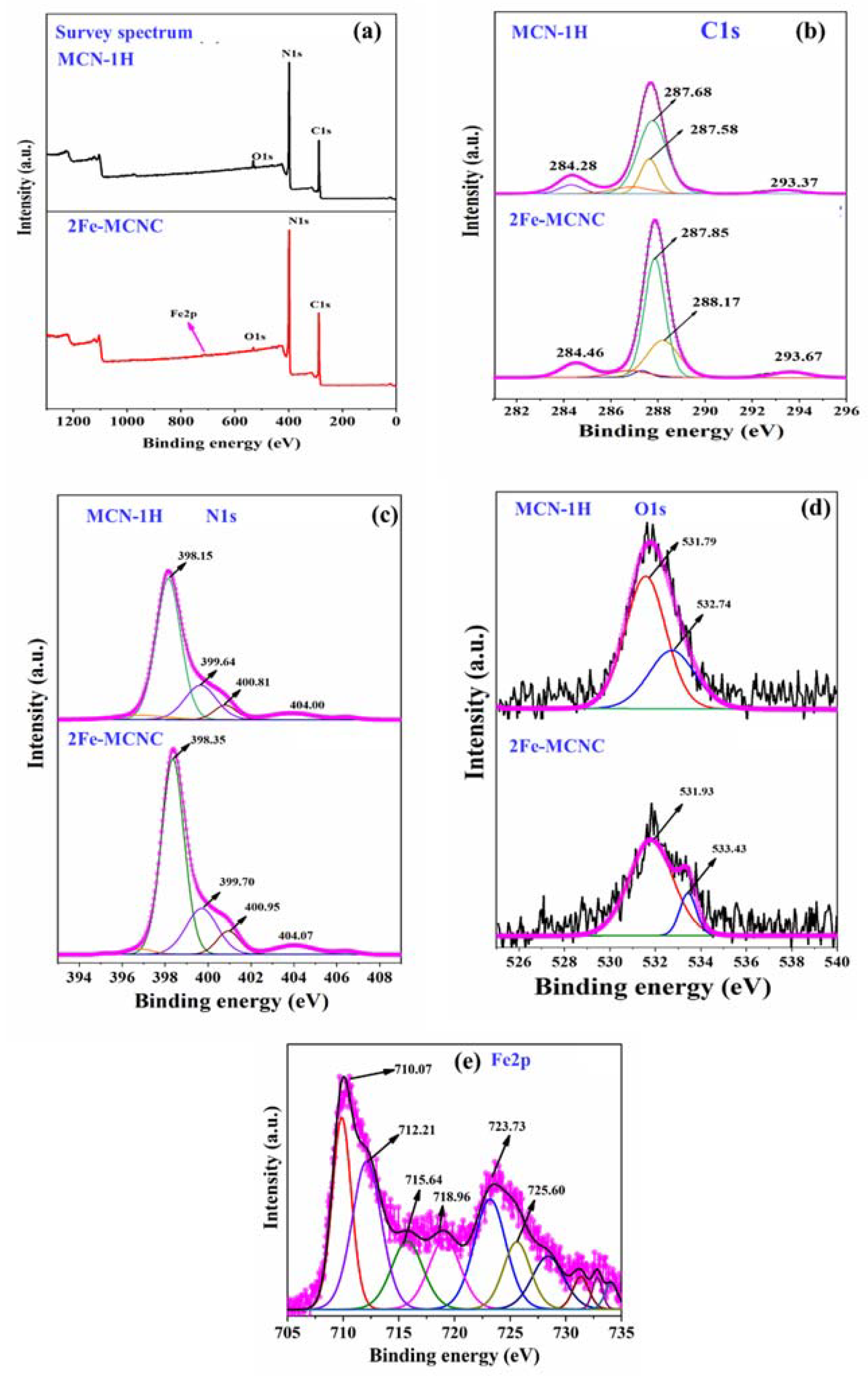
| Samples | N | C | O | Fe |
|---|---|---|---|---|
| MCN-1H | 53.91 | 43.04 | 3.05 | 0 |
| 1Fe-MCNC | 51.04 | 47.31 | 1.56 | 0.09 |
| 2Fe-MCNC | 56.15 | 42.28 | 1.30 | 0.19 |
| 3Fe-MCNC | 56.34 | 42.15 | 1.20 | 0.19 |
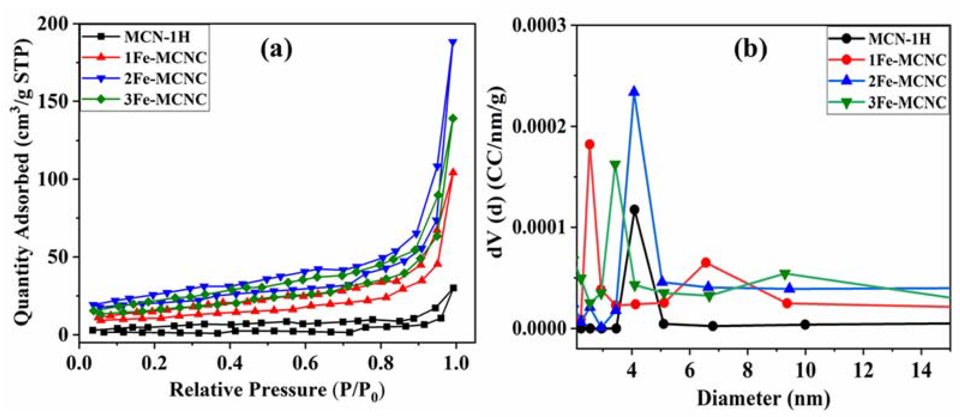
| Samples | BET Surface Area (m2 /g) | Pore Volume (cm3 /g) | Average Pore Diameter (nm) |
|---|---|---|---|
| MCN-1H | 2.89 | 0.055 | 1.50 |
| 1Fe-MCNC | 13.69 | 0.15 | 2.50 |
| 2Fe-MCNC | 23.67 | 0.26 | 4.0 |
| 3Fe-MCNC | 19.20 | 0.20 | 1.70 |
| Samples | First Cycle | Second Cycle | Third Cycle |
|---|---|---|---|
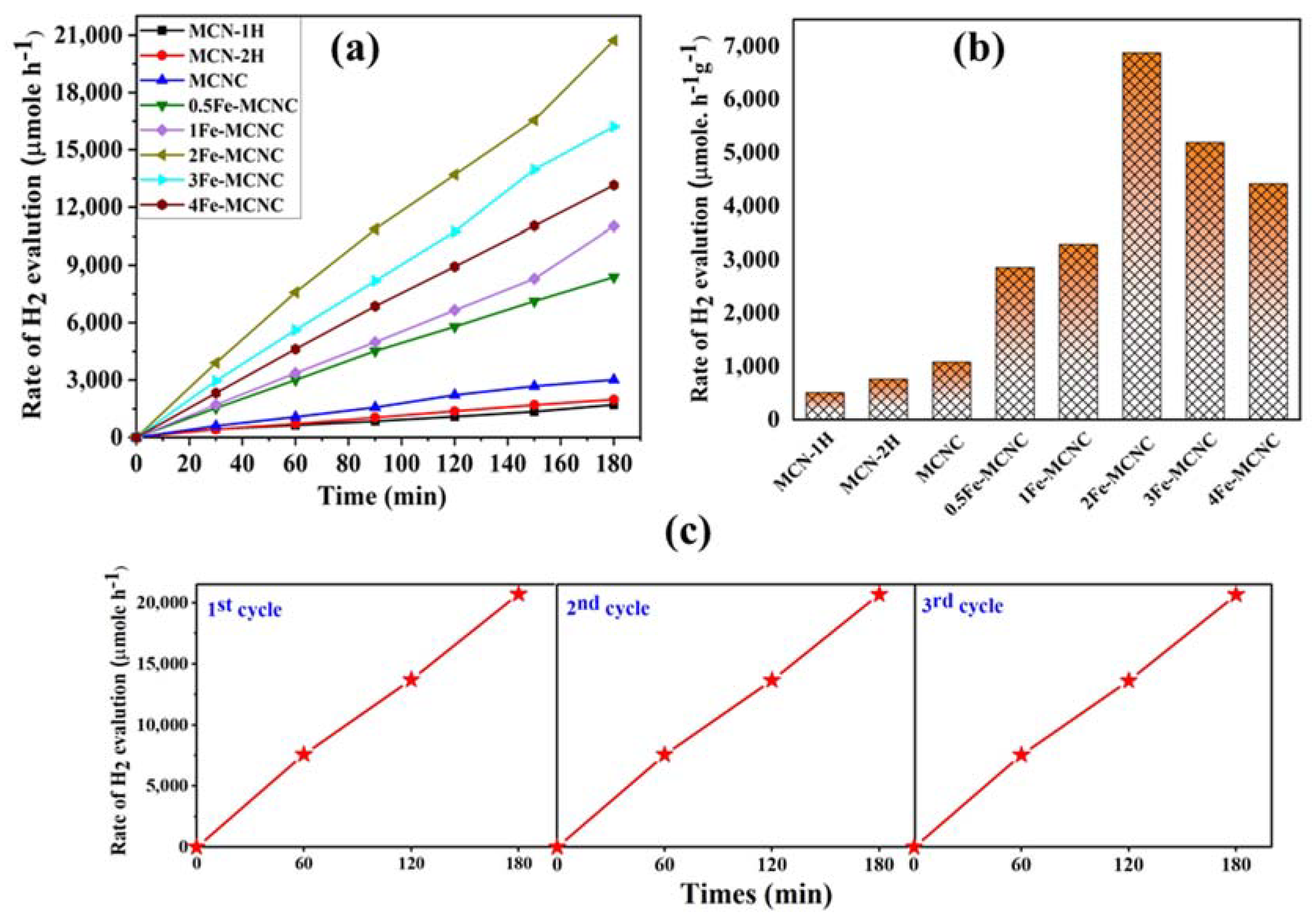
| 2Fe-MCNC SD values | 8820.83 | 8801.62 | 8787.42 |
| MCN-1H SD values | 572.95 | 561.01 | 553.67 |
Disclaimer/Publisher’s Note: The statements, opinions and data contained in all publications are solely those of the individual author(s) and contributor(s) and not of MDPI and/or the editor(s). MDPI and/or the editor(s) disclaim responsibility for any injury to people or property resulting from any ideas, methods, instructions or products referred to in the content. |
© 2023 by the authors. Licensee MDPI, Basel, Switzerland. This article is an open access article distributed under the terms and conditions of the Creative Commons Attribution (CC BY) license (https://creativecommons.org/licenses/by/4.0/).
Share and Cite
Koli, V.B.; Murugan, G.; Ke, S.-C. Self-Assembled Synthesis of Porous Iron-Doped Graphitic Carbon Nitride Nanostructures for Efficient Photocatalytic Hydrogen Evolution and Nitrogen Fixation. Nanomaterials 2023, 13, 275. https://0-doi-org.brum.beds.ac.uk/10.3390/nano13020275
Koli VB, Murugan G, Ke S-C. Self-Assembled Synthesis of Porous Iron-Doped Graphitic Carbon Nitride Nanostructures for Efficient Photocatalytic Hydrogen Evolution and Nitrogen Fixation. Nanomaterials. 2023; 13(2):275. https://0-doi-org.brum.beds.ac.uk/10.3390/nano13020275
Chicago/Turabian StyleKoli, Valmiki B., Gavaskar Murugan, and Shyue-Chu Ke. 2023. "Self-Assembled Synthesis of Porous Iron-Doped Graphitic Carbon Nitride Nanostructures for Efficient Photocatalytic Hydrogen Evolution and Nitrogen Fixation" Nanomaterials 13, no. 2: 275. https://0-doi-org.brum.beds.ac.uk/10.3390/nano13020275