
A Novel Arch-Shape Nanogenerator Based on Piezoelectric and Triboelectric Mechanism for Mechanical Energy Harvesting

Abstract
:1. Introduction
2. Results and Discussion
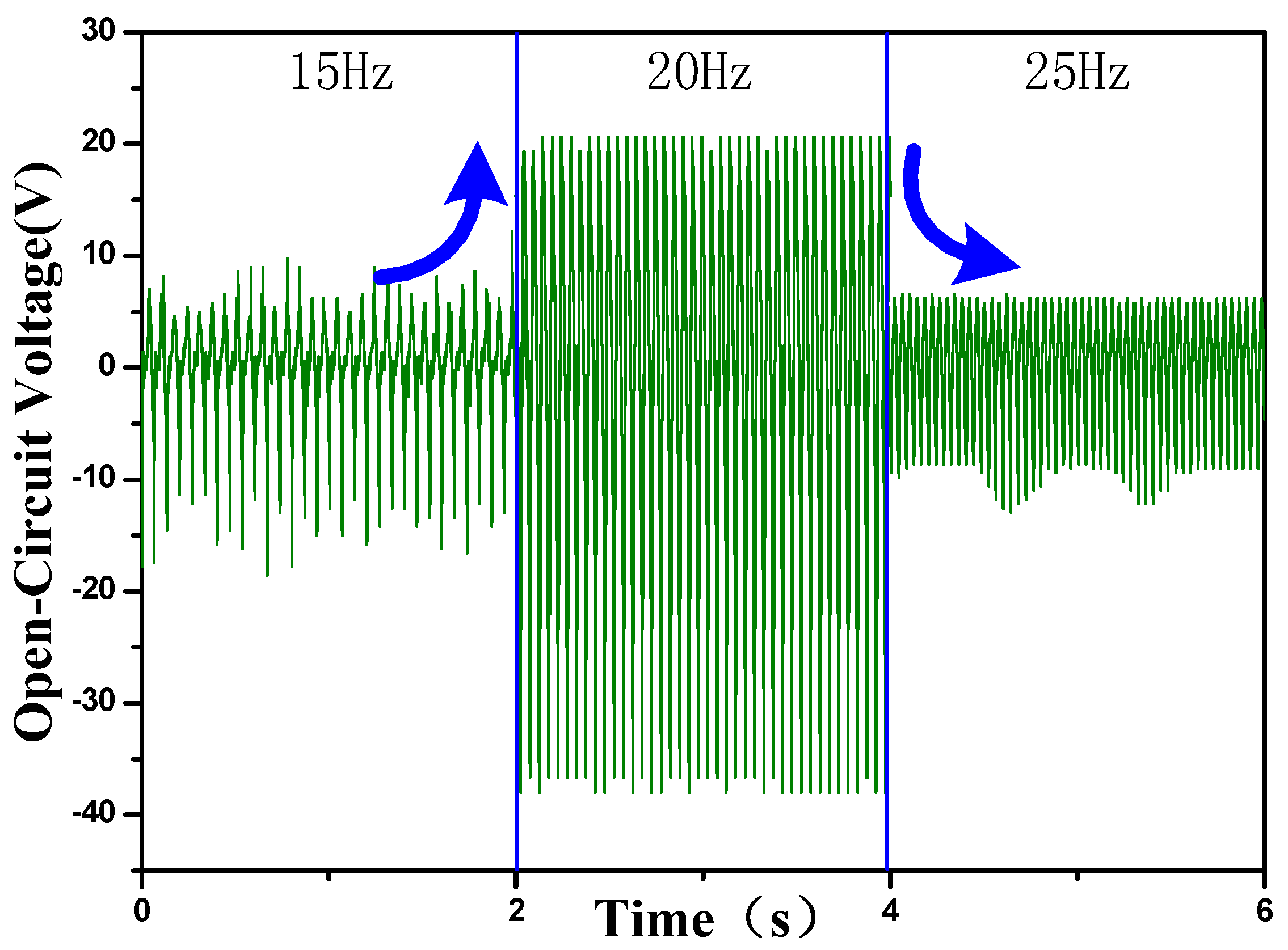
2.1. Frequency Effect

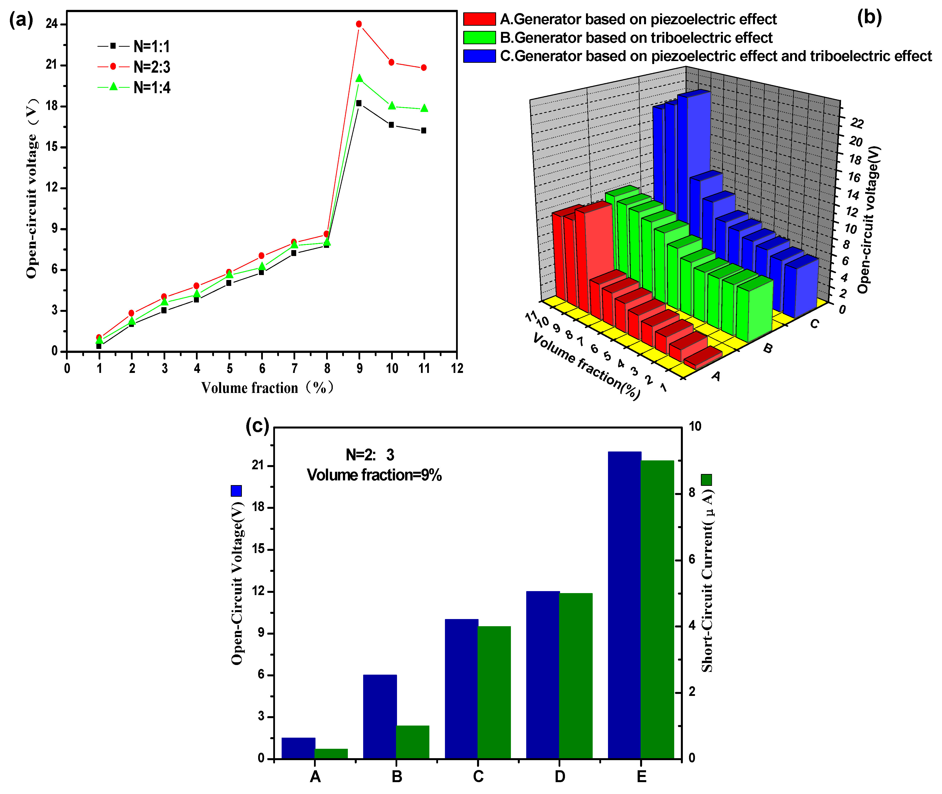
2.2. Electrical Output Performance

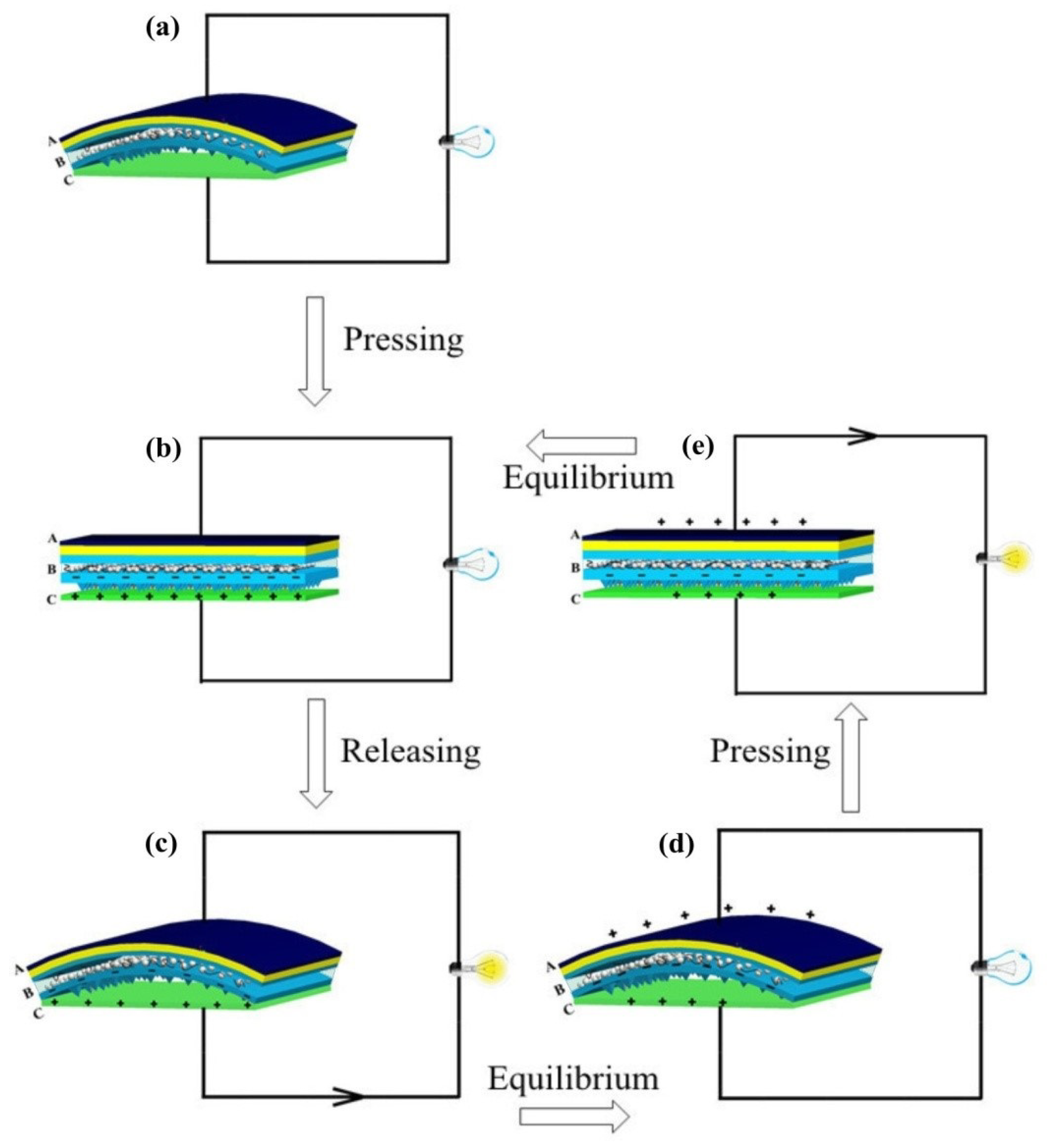
2.3. Working Principle


| Layer | (a) | (b) | (c) | (d) | (e) | |||||
|---|---|---|---|---|---|---|---|---|---|---|
| piezo | tribo | piezo | tribo | piezo | tribo | piezo | tribo | piezo | tribo | |
| A | −σP | 0 | −σP | 0 | −σP | 0 | −σP | +Δσ | −σp | +Δσ |
| B | 0 | 0 | 0 | −σT | 0 | −σT | 0 | −σT | 0 | −σT |
| C | 0 | 0 | +σP | +σT | +σP | +σT | 0 | +σT − Δσ | 0 | +σT − Δσ |
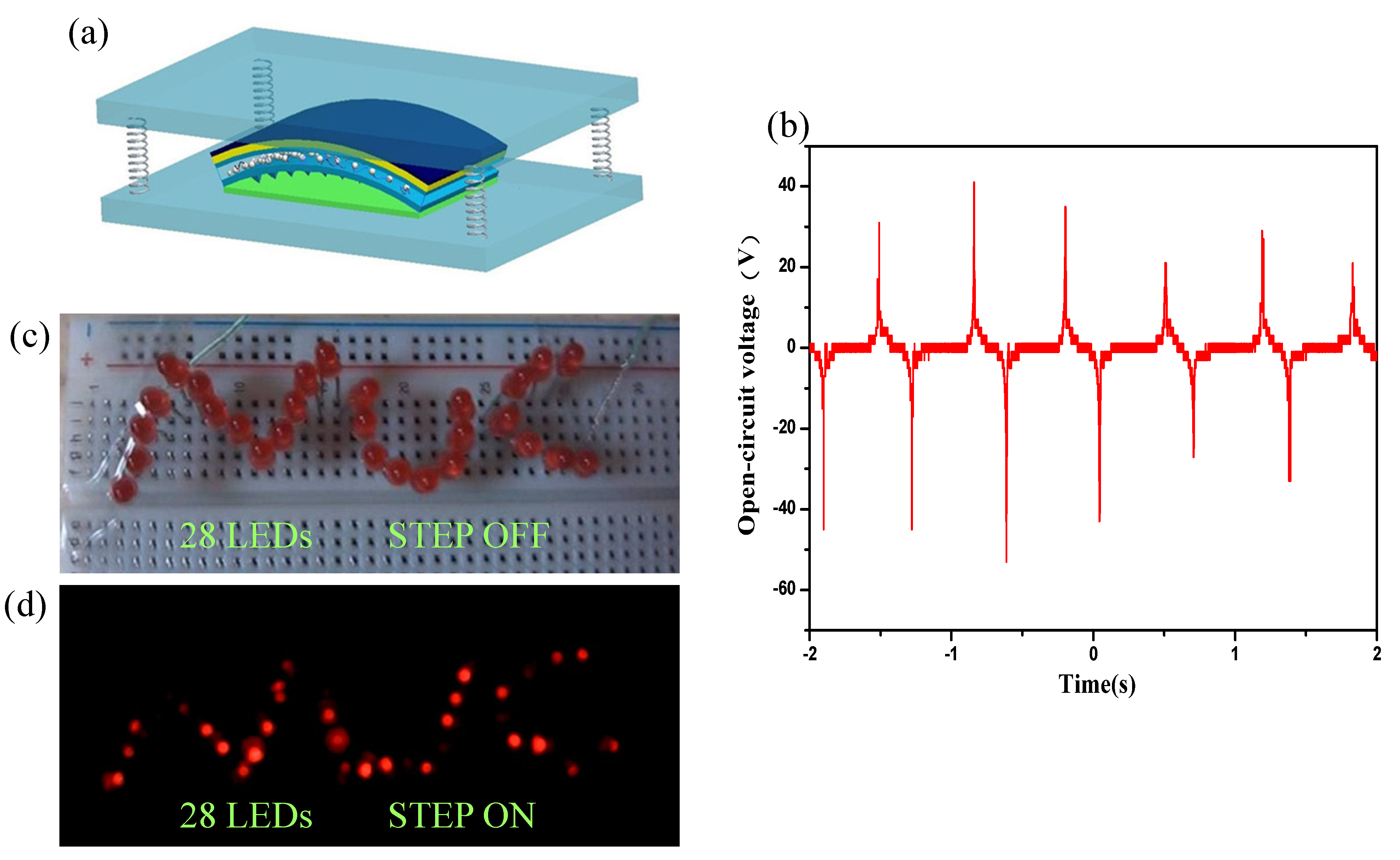
2.4. Application

3. Experimental
3.1. Reagents and Apparatus
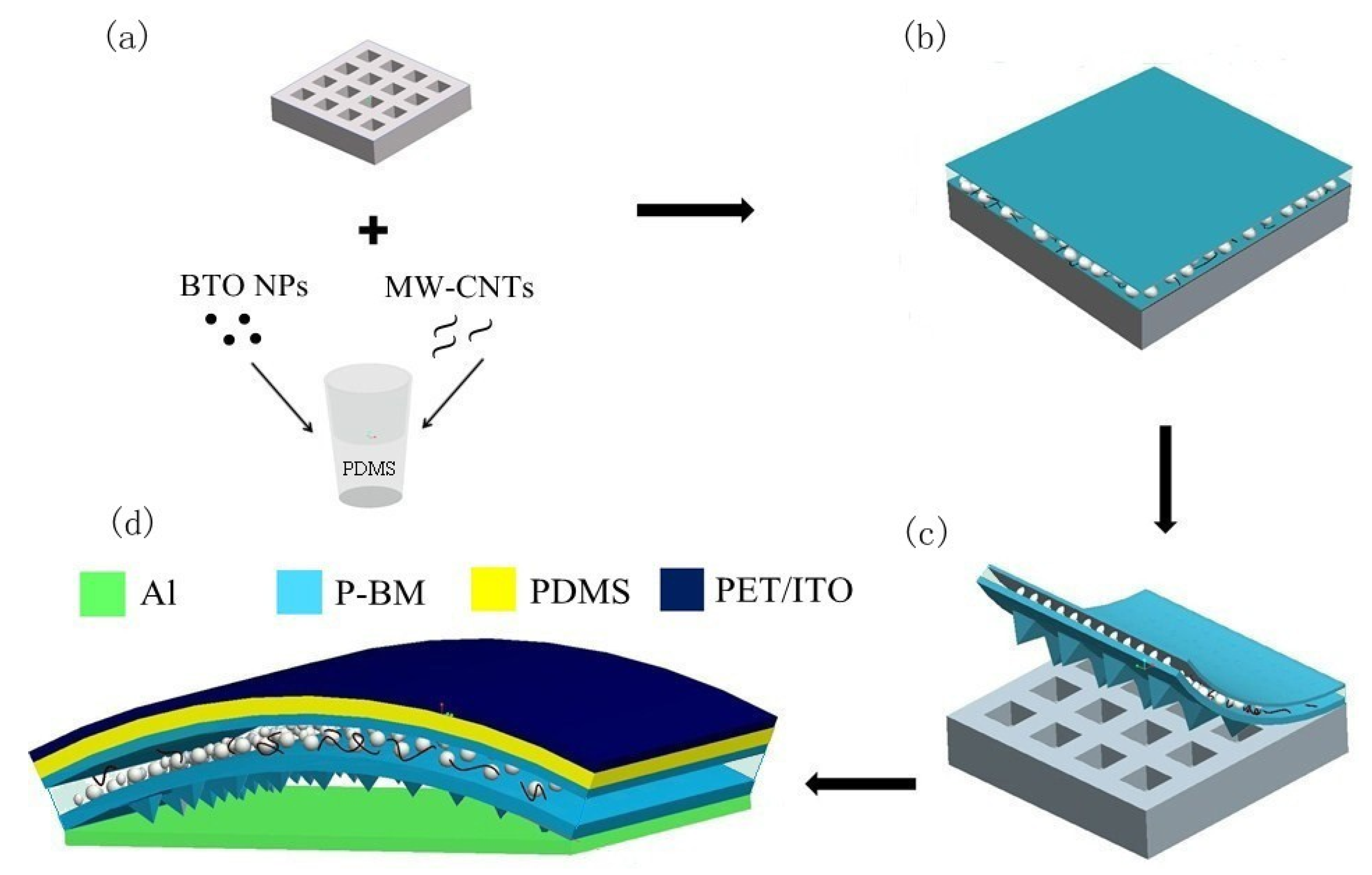
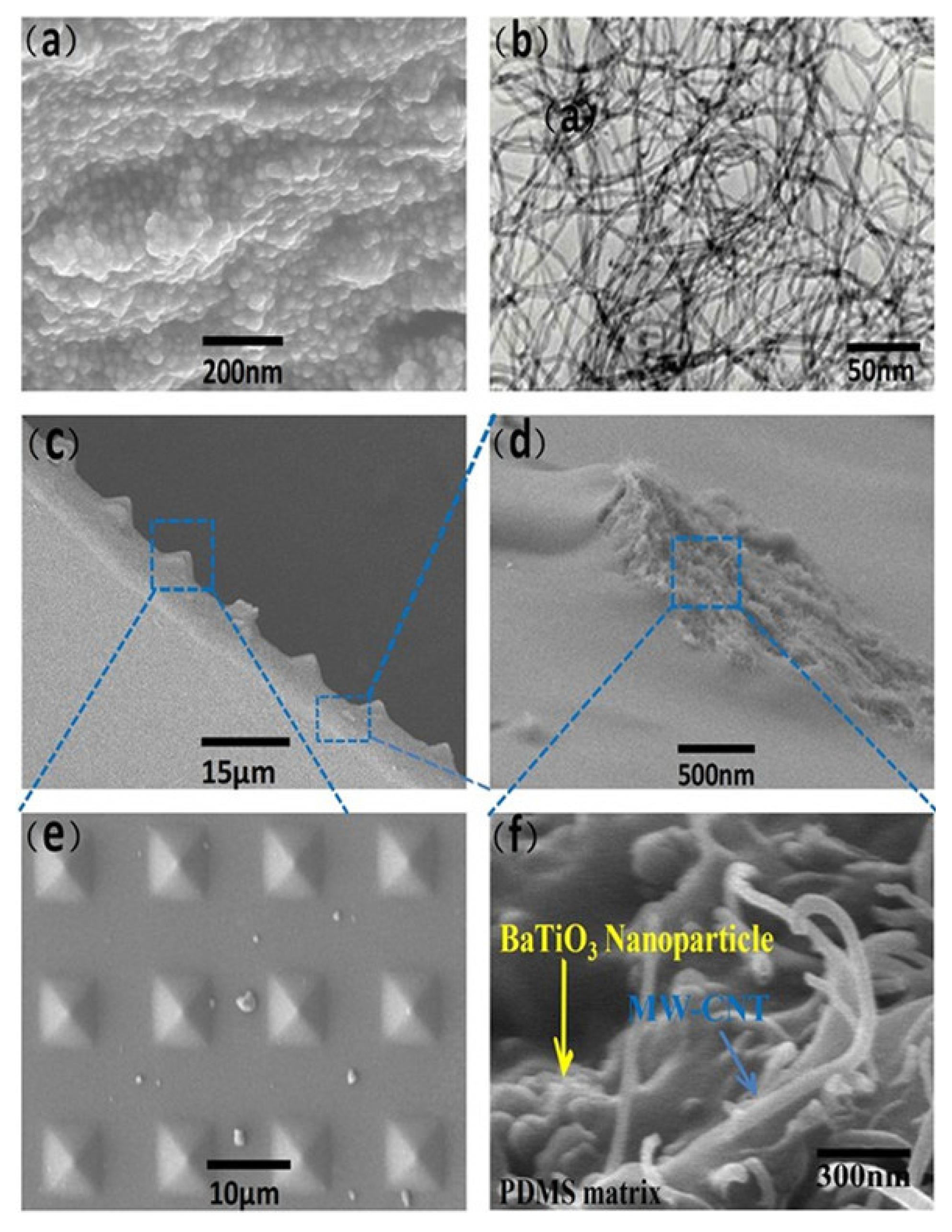
3.2. Preparation of the Composites


4. Conclusions
Acknowledgments
Author Contributions
Conflicts of Interest
References
- Wang, Z.L.; Song, J. Piezoelectric nanogenerators based on zinc oxide nanowire arrays. Science 2006, 312, 242–246. [Google Scholar] [PubMed]
- Beeby, S.P.; Tudor, M.J.; White, N.M. Energy harvesting vibration sources for microsystems applications. Meas. Sci. Technol. 2006, 17, R175–R195. [Google Scholar]
- Wang, Z.L. Self-powered nanosensors and nanosystems. Adv. Mater. 2012, 24, 280–285. [Google Scholar] [CrossRef]
- Park, K.I.; Jeong, C.K.; Ryu, J.; Hwang, G.T.; Lee, K.J. Flexible and large-area nanocomposite generators based on lead zirconate titanate particles and carbon nanotubes. Adv. Energy Mater. 2013, 3, 1539–1544. [Google Scholar] [CrossRef]
- Chen, C.Y.; Zhu, G.; Hu, Y.; Yu, J.W.; Song, J.; Cheng, K.Y.; Peng, L.H.; Chou, L.J.; Wang, Z.L. Gallium nitride nanowire based nanogenerators and light-emitting diodes. ACS Nano 2012, 6, 5687–5692. [Google Scholar] [CrossRef] [PubMed]
- Hu, Y.; Zhang, Y.; Xu, C.; Zhu, G.; Wang, Z.L. High-output nanogenerator by rational unipolar assembly of conical nanowires and its application for driving a small liquid crystal display. Nano Lett. 2010, 10, 5025–5031. [Google Scholar]
- Hu, Y.; Zhang, Y.; Xu, C.; Lin, L.; Snyder, R.L.; Wang, Z.L. Self-powered system with wireless data transmission. Nano Lett. 2011, 11, 2572–2577. [Google Scholar] [CrossRef]
- Park, K.I.; Lee, M.; Liu, Y.; Moon, S.; Hwang, G.T.; Zhu, G.; Kim, J.E.; Kim, S.O.; Kim, D.K.; Wang, Z.L.; et al. Flexible nanocomposite generator made of BaTiO3 nanoparticles and graphitic carbons. Adv. Mater. 2012, 24, 2999–3004. [Google Scholar] [PubMed]
- Zhu, G.; Chen, J.; Liu, Y.; Bai, P.; Zhou, Y.S.; Jing, Q.; Pan, C.F.; Wang, Z.L. Linear-grating triboelectric generator based on sliding electrification. Nano Lett. 2013, 13, 2282–2289. [Google Scholar] [PubMed]
- Zhu, G.; Pan, C.; Guo, W.; Chen, C.Y.; Zhou, Y.; Yu, R.; Wang, Z.L. Triboelectric-generator-driven pulse electrodeposition for micropatterning. Nano Lett. 2012, 12, 4960–4965. [Google Scholar] [CrossRef] [PubMed]
- Bai, P.; Zhu, G.; Lin, Z.H.; Jing, Q.; Chen, J.; Zhang, G.; Ma, J.S.; Wang, Z.L. Integrated multilayered triboelectric nanogenerator for harvesting biomechanical energy from human motions. ACS Nano 2013, 7, 3713–3719. [Google Scholar] [CrossRef] [PubMed]
- Yang, Y.; Lin, L.; Zhang, Y.; Jing, Q.; Hou, T.C.; Wang, Z.L. Self-powered magnetic sensor based on a triboelectric nanogenerator. ACS Nano 2012, 6, 10378–10383. [Google Scholar] [CrossRef] [PubMed]
- Zhang, X.S.; Han, M.D.; Wang, R.X.; Zhu, F.Y.; Li, Z.H.; Wang, W.; Zhang, H.X. Frequency-multiplication high-output triboelectric nanogenerator for sustainably powering biomedical microsystems. Nano Lett. 2013, 13, 1168–1172. [Google Scholar] [CrossRef] [PubMed]
- Han, M.D.; Zhang, X.S.; Liu, W.; Sun, X.M.; Peng, X.H.; Zhang, H.X. Low-frequency wide-band hybrid energy harvester based on piezoelectric and triboelectric mechanism. Sci. China Technol. Sci. 2013, 56, 1835–1841. [Google Scholar] [CrossRef]
- Pötschke, P.; Kretzschmar, B.; Janke, A. Use of carbon nanotube filled polycarbonate in blends with montmorillonite filled polypropylene. Compos. Sci. Technol. 2007, 67, 855–860. [Google Scholar]
- Wang, S.; Lin, L.; Wang, Z.L. Nanoscale triboelectric-effect-enabled energy conversion for sustainably powering portable electronics. Nano Lett. 2012, 12, 6339–6346. [Google Scholar] [PubMed]
© 2014 by the authors; licensee MDPI, Basel, Switzerland. This article is an open access article distributed under the terms and conditions of the Creative Commons Attribution license (http://creativecommons.org/licenses/by/4.0/).
Share and Cite
Xue, C.; Li, J.; Zhang, Q.; Zhang, Z.; Hai, Z.; Gao, L.; Feng, R.; Tang, J.; Liu, J.; Zhang, W.; et al. A Novel Arch-Shape Nanogenerator Based on Piezoelectric and Triboelectric Mechanism for Mechanical Energy Harvesting. Nanomaterials 2015, 5, 36-46. https://0-doi-org.brum.beds.ac.uk/10.3390/nano5010036
Xue C, Li J, Zhang Q, Zhang Z, Hai Z, Gao L, Feng R, Tang J, Liu J, Zhang W, et al. A Novel Arch-Shape Nanogenerator Based on Piezoelectric and Triboelectric Mechanism for Mechanical Energy Harvesting. Nanomaterials. 2015; 5(1):36-46. https://0-doi-org.brum.beds.ac.uk/10.3390/nano5010036
Chicago/Turabian StyleXue, Chenyang, Junyang Li, Qiang Zhang, Zhibo Zhang, Zhenyin Hai, Libo Gao, Ruiting Feng, Jun Tang, Jun Liu, Wendong Zhang, and et al. 2015. "A Novel Arch-Shape Nanogenerator Based on Piezoelectric and Triboelectric Mechanism for Mechanical Energy Harvesting" Nanomaterials 5, no. 1: 36-46. https://0-doi-org.brum.beds.ac.uk/10.3390/nano5010036