Advances in Optomechatronics: An Automated Tilt-Rotational 3D Scanner for High-Quality Reconstructions


1
Department of Engineering, University of Perugia, 06125 Perugia, Italy
2
Department of Research and Development, V-GER SRL, Castenaso, 40055 Bologna, Italy
*
Author to whom correspondence should be addressed.
Photonics 2018, 5(4), 42; https://0-doi-org.brum.beds.ac.uk/10.3390/photonics5040042
Submission received: 7 September 2018
/
Revised: 23 October 2018
/
Accepted: 25 October 2018
/
Published: 29 October 2018
Abstract
:3D vision systems are more and more required in a large variety of applications and mostly for mechanical and medical purposes. This paper presents the study and realization of a prototype of a structured light automated tilt-rotational 3D vision system for high-quality reconstructions of components of various sizes and in cases of freeform and complex surfaces. The main goal of this research work was to develop an instrument with the following main novelties: configurability for different object sizes, high precision and resolution levels and ability to automatically generate the mesh representing the full scanned objects without any intervention of the operator by means of a 2 degrees of freedom automated tilt-rotational mechanical positioning system. A detailed analysis of the instrument and the procedures and results of the performance tests are presented, together with the examination of possible strategies to obtain a better performance, especially by the calibration and the synchronization between the optical and the mechanical systems. As a result, the prototype and the performance parameters resulting from the experimental campaigns, are reported.
1. Introduction
Three-dimensional vision systems are more and more required in a large variety of applications and mostly for mechanical and medical purposes. Non-contact optical scanning systems are quite recent and are revolutionizing metrology and mechanical and medical design, not only for their precision and ease of use, but also for the wide range of applications they can be used for. A 3D scanner is an instrument for analyzing and reconstructing real objects or environments in a 3D digital model and to gather information about shape, color, and possibly also surface characteristics.
For instance, reverse engineering [1,2] and the development of industrial design or medical components [3,4,5], surface analysis [6,7], wear assessment [3,8,9,10,11,12], deformation analysis and quality control [3,13], robot positioning, and guiding systems [14,15,16] are typical industrial and medical applications where 3D digital reconstructions are crucial. Three-dimensional scanners are based on various working principles and technologies with different advantages, limitations, and costs. The output of a 3D scanner is a point cloud or, directly, a triangular mesh, representing the spatial coordinates of each point of the object’s surface.
Most of the 3D vision and scanning systems do not allow us to get a full model of the target object in a single scanning session and in this case, many scans are generally necessary, sometimes even hundreds, from different angles, to obtain information from all sides of the object. These scans must be referenced to a common reference system (a process generally called alignment or registration) and then merged together to create a complete model [8]. Some 3D scanners are able to automatically capture the full 3D digital model of the object in a single scanning session, which means that the operations of scanning, alignment, and fusion are managed automatically by the scanning instruments, implying very few or no interventions of the operator.
Some of the “automatic” 3D scanners are handheld and portable, and others are desktop laboratory scanners. If they are handheld, the operator must hold the device during the whole scanning session and turn the object around, or move his arm along the object, while it rotates on a rotary table. Desktop 3D scanners are usually tripod-mounted, or they are embedded in a fixed-size case with or without a positioning mechanism. If there is a positioning mechanism, the target object can be automatically moved in the scanning volume.
The 3D vision and scanning system presented in this paper belongs to this last category of 3D scanners. The device is a robotic 3D desktop scanner for industrial and medical laboratories. The prototype system will be used for high-quality reconstructions of components of various sizes and its performance in terms of trueness and precision (and both repeatability and reproducibility) will be analyzed.
1.1. Related Works
Desktop automated 3D scanners are especially used for medical applications and for artwork and jewel fabrication, but although optical 3D scanners have been widely used in recent years, just a few of them are numbered in the scientific literature. Some research works related to automated desktop scanners are briefly summarized next.
Son et al. in [1] proposed an automated measuring system for parts having a freeform surface, with the hardware system consisting of an existing laser scanning device and setup fixtures to provide a proper location and orientation for the part to be measured. The working principle of the 3D laser scanner used in this paper is the laser triangulation: a laser stripe is projected onto the object’s surface and the reflected beam is detected by CCD cameras. The laser probe is mounted on a three-axis transport mechanism that moves along the scan path and rotates in two directions. In the scanning procedure, various scanning parameters are considered in the generation of optimal scan paths, such as the view angle, the depth of field, the length of the stripe, and the occlusion. The measured point data sets are automatically captured and registered using the rotation angles of a rotary table. The quality of the point data is evaluated by checking the difference between the CAD model and the measured data. In this work, just one scanning volume is considered and the results show the following standard deviations between the nominal CAD model and the measured digital model: 0.04087 mm (positive value) and 0.03894 mm (negative value). These values give information about the accuracy of the scanning instrument, but it assumes that the nominal CAD model exactly reproduces the physical model of the real object.
In References [17,18] the principles of a desktop dental and jewelry 3D scanner are described. The instrument is an automated 3D measuring device. The automatic positioning mechanism is conceived through two different solutions: a linear stage which is mounted with a teeth or jewel model and supports the model, or a main rotation and support unit, installed inside the main body and supporting a plaster model, with a secondary rotation and support unit which supports the impressions and rotates regardless of the rotation of the main unit. In both cases, the optical scanning unit is installed inside the main body and obtains the video information of the target object. These works present instruments where only the positioning mechanism can move and the scanning volume is fixed.
In References [19,20] the working principles of desktop 3D scanners are described. The 3D scanner disclosed in Reference [19] comprises of a projector unit projecting a structured beam of probe light onto the object, an imaging unit to collect 2D images of the object when the object is illuminated, and an actuator to control the position of the structured probe light beam at the object by rotating a movable portion of the projector unit around a pivoting axis. The device disclosed in Reference [20] is a structured light 3D scanner based on the principle of triangulation. A light source generates a light pattern, two cameras with two-dimensional sensors record the reflection of the light pattern from a target object, and one axis moves the cameras. Thus, differently from the other devices, in these scanners, the optical assembly comprises movable parts.
Chen et al. in [21] propose a 3D optical measurement system based on fringe projection to be applied for facial prosthesis fabrication. The instrument is cost-effective and consists of two measurement sensors, which can scan and register both sides of the patients’ face. The scanning head is movable by a 2 degrees of freedom mechanism. No data about the performance parameters are disclosed, but the instrument was validated through clinical trials.
Dumitrache et al. in Reference [7] present a robotic 3D laser scanning system for automatic inspection. The laser scanner was mounted on a 6 DoFs (degrees of freedom) vertical articulated robot, and the inspection procedure was allowed to automatically check the geometrical features of the target object, against reference part models. A software synchronizes the 7 DoFs robot and the turntable mechanism with the laser scanning along the motion pattern and the whole system was integrated with a 2D vision system.
1.2. System Innovation
The instrument proposed in this paper is a desktop 3D optical scanner based on the principle of structured light active triangulation. In a desktop 3D scanner with an automated positioning mechanism, the number of degrees of freedom (DoFs) of the positioning system affects the completeness of the resulting digital model. Thus, if, for example, the positioning mechanism consists of a single DoF rotary table, the full digital model must be reconstructed by scanning the object in two or more different sessions in order to get the surface information from all the perspectives. In the case of tilt-rotational positioning mechanisms, a single scanning session is often enough to get the full 3D digital model.
According to the current scientific literature, the already known automated desktop 3D scanners are suitable for scanning objects of specific sizes and are not able to be configured to operate with different scanning volumes. Moreover, the scanning apparatuses are able to move the optical parts or the scanning object with mechanisms of maximum 7 DoFs.
On the contrary, the goal of the device here described is to generate complete 3D reconstructions of objects of various sizes, in a range from about 5 mm to about 500 mm. This is possible thanks to a particular structure of the scanner, that is modular and adjustable for different purposes. In particular, the scanner has been conceived with an extendable framework with fixtures in order to always get the right working distance and positioning for objects of several sizes. The device typically has seven degrees of freedom for the framework and one or two for the worktable. Both the optical assembly and the scanning object can be moved in order to achieve a complete high-quality reconstruction.
Most of the prior automated scanners use the principle of lasers or structured light triangulation with multiple sensors, while in this work, the proposed instrument consists of a single projector and a single imaging sensor. In the work presented in this paper, the whole scanning and mechanical systems were developed by avoiding the use of already existing instruments.
The instrument presents different performance parameters for each scanning volume. In prior cited works, the performance parameters of 3D scanning instruments were tested in just one scanning volume and assuming the nominal CAD model to be a reference. This assumption has been overcome in this paper as the physical model used for the performance test was measured by a contact coordinate measuring machine (CMM).
Furthermore, differently from mechanical positioning systems for automatic machines presented in the current scientific literature, the tilt-rotational worktable used in this work can be referenced and synchronized with the optical sensors, both with a precise mechanical calibration for minimizing positioning errors and by means of the software which allows us to compensate for eventual misalignments by means of ICP (iterative closest point) algorithms, as shown below.
2. Materials and Methods: Theoretical Principles and Fundamentals of the 3D Scanning Apparatus
2.1. Basic Structure and Configurations
The scanning apparatus is basically composed of four parts: the optical scanning head, the mechanical positioning system, the electronics, and the software. The applied scanning principle is the structured light active triangulation, based on the projection of Gray coded and phase shifted stripe patterns onto the target object. The deformation of the stripes on the object’s surface is recorded by a single industrial black/white camera and processed by the dedicated scanning software to calculate the coordinates at all the points of the object’s surface. The LED projector allows projections of different color beams: red, green, blue, and white. Shiny objects must be properly opacified by spray talcum powders with microparticles in order to prevent unwanted reflections.
The instrument is configurable and adjustable in all its components and can be configured to cover different scanning volumes, for scanning objects from about 5 mm to about 500 mm of the characteristic size.
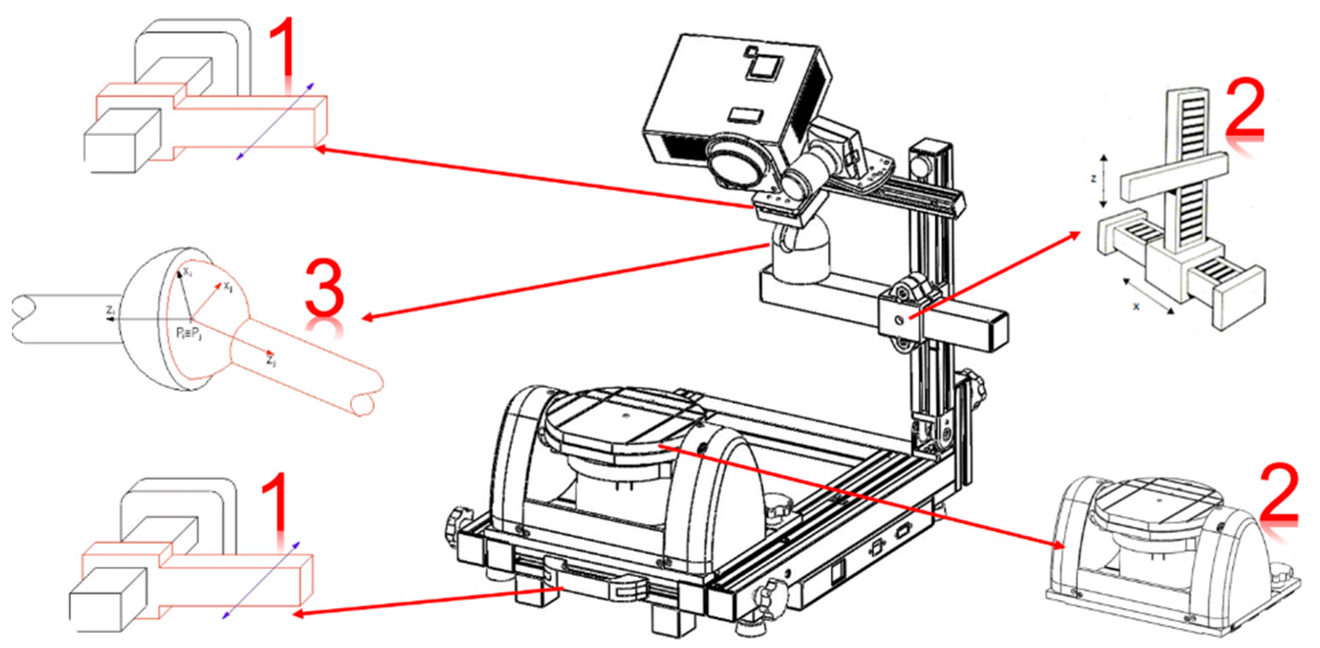
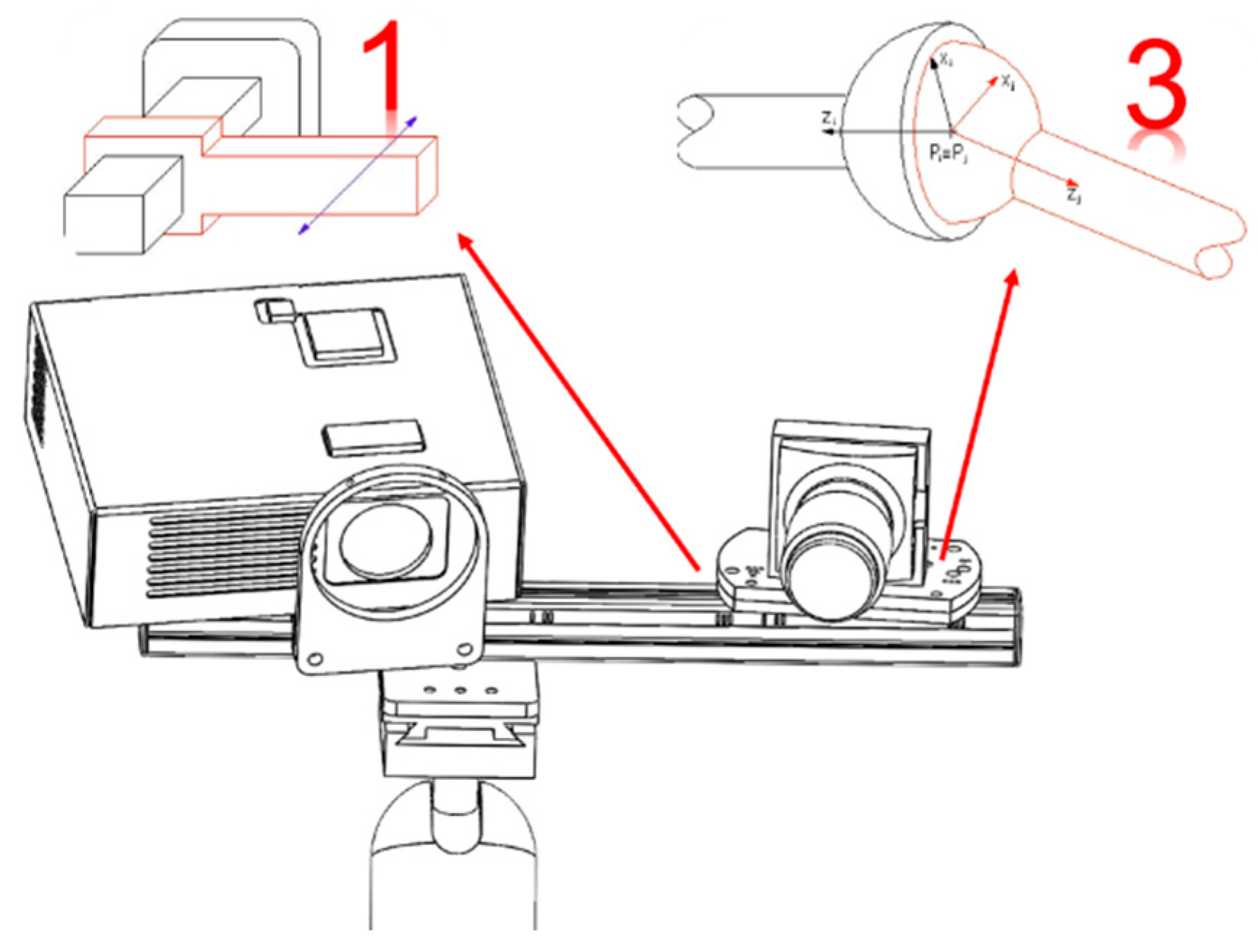
There is one translational DoF at the extendable base of the framework, two at the double translation of the horizontal and vertical beam, one on the ball joint slab, three rotational DoFs on the ball joint and a maximum of two on the tilt-rotational worktable (Figure 1). The optical assembly is provided with four extra DoFs: one translation and three rotations of the sensing camera, as shown in Figure 2.
The framework is extendable and equipped with specific fixtures which help to find the right extension of the base, the position of the mechanical positioning system, and the height of the optical assembly, depending on the size of the specimen. Additionally, the optical assembly is provided with fixtures and movable parts in order to fix the camera in the right position with respect to the projector in order to cover all the scanning volumes. In fact, the camera and the projector are mounted on an aluminum guide, where the projector is kept at a fixed position, while the camera is mounted on a slab which allows the camera to be moved in four ways. In fact, the camera can slide closer or farther from the projector, it can rotate around an axis perpendicular to the guide, and it can tilt around the other two axes in the plane of the guide by using four grub screws. Furthermore, the aluminum guide is mounted on an adjustable ball joint to grant that the field of view of the optical assembly is centered with respect to the object on the scene. The right positioning of the camera with respect to the projector, and of the entire optical assembly with respect to the scene, is reached when the camera’s and the projector’s optical axes intersect at the center of the scene.
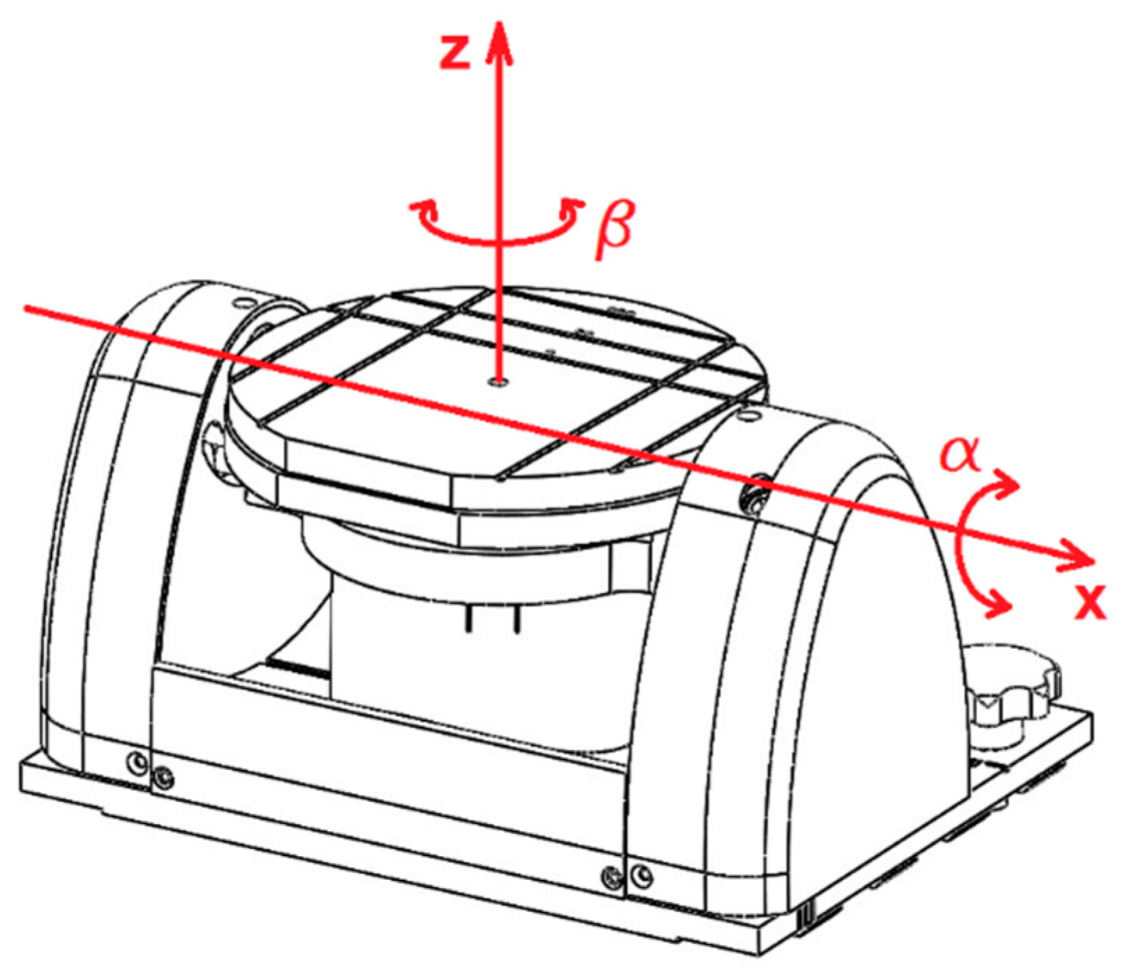
The two degrees of freedom of the tilt-rotational system is the angle β (rotation around z) and α (rotation around x), as shown in Figure 3. The control system utilizes an Arduino controller and two drivers (DM422C, Leadshine Technology, Shenzhen, China) for two stepper motors (Lam Technologies, Sesto Fiorentino FI, Italy).
The input parameters for the control system are the angular positions α, β and the angular velocities and .
Therefore, the rotational matrixes of the mechanical system are [26]:
Different calibration plates have been developed to optically and mechanically calibrate the instrument for various scanning volumes.
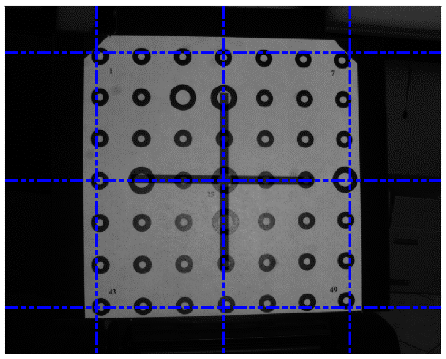
The procedure to configure the system for one specific scanning volume and to reach the proper optical alignment starts by moving the ball joint until the center of the projection is positioned onto the center of the calibration plate and the projector is brought into focus. All these operations can be controlled and visualized by using the scanning software. Then the camera is made to slide to match the right distance from the projector, and it is rotated and tilted until its optical axis intersects the center of the calibration plate, as shown in Figure 4. The blue lines in Figure 4 represent the camera reference grid and the black cross represents the center of the projection. All these operations are simplified by special reference signs on the optical components.
2.2. Optical and Mechanical Calibrations
The optical assembly and the mechanical positioning system must be calibrated every time the apparatus is configured to scan one of the selectable scanning volumes.
The optical calibration has the purpose of determining the intrinsic parameters of the camera and compensating for radial distortion [27]. The intrinsic parameters are represented by f, which is the focal length; αx and αy, which are the focal lengths expressed in pixels; Cx and Cy, which are the principal point pixels coordinates (computer image coordinate for the origin in the image plane), σx and σy, which are the radial distortions, px and py, which express the sizes of the pixel. Some of the intrinsic parameters appear in the matrix K.
The calibration plates have been developed in order to calibrate the intrinsic parameters and correct distortion. The calibration plates are white square slabs with white circles with black bold contours. For each calibration plate, the value of the distance between the specific points was measured by means of a vision measuring microscope (Quick Scope, Mitutoyo, Japan) and taken as a reference value to calculate the optical performance of the scanner during the optical calibration. Each scanning volume must be preferably calibrated with two plates: a bigger one for the optical calibration and a smaller one for the mechanical calibration.
The software module has the ability to perform semi-automatic guided optical calibration procedures. The software wizard guides the operator to take a certain number of snapshots at different locations of the calibration plate in the scanning volume and on the tilt-rotational positioning system. Finally, it accomplishes the calculation of the final precision in terms of pixels, throughout an iterative procedure.
The mechanical calibration allows us to extract the extrinsic parameters, which can be represented by the matrixes R and T, where ri are the rotation coefficients, expressed in a function of the Euler angles and Ti are the translational vector components. Thus, R is the rotational matrix and T is the translational vector to perform a rigid body transformation from the 3D coordinates of the specimen to be reconstructed (x, y, z) into the 3D coordinates of the camera system (xc, yc, zc) [28,29].
The mechanical calibration follows an automatic software-guided procedure consisting of a certain number of automatic movements of the positioning worktable, with the aim of moving a specific calibration plate to cover the entire scanning volume. This calibration allows us to get automatic alignments of all the frames during the scanning sessions and to better compensate for distortions. During the mechanical calibration, the iterative calibration algorithm calculates the displacements (rotation angles) of the calibration plate by measuring the point-to-point vector on the 2D images of the plate in the four positions. From this information, the steps of the stepper motors are calculated and used for the next positioning procedures and to register different scanning frames, without using ICP (iterative closest point) algorithms. The mechanical calibration tool is also able to report the average error in terms of pixels and the angular error in terms of the percentage of degrees. Obviously, these values must be kept as small as possible.
The measuring performance parameters of the instrument depends on the calibration phases. In this work, some strategies have been used to improve the performance. One of the strategies is to use calibration plates with a certified and measured value of the distance between specific points. This implies that the measuring error of the scanning instrument can be lowered, as the measured values of the point-to-point distance can be entered into the software and used as a scale and convergence factor of the iterative calibration algorithm. Even the synchronization between the optical and the mechanical systems is a topic of significance for improving the measuring capabilities. In fact, if the scanning procedure starts when the mechanism is not correctly positioned or if the mechanical calibration has not been properly done, the result will contain a certain registration error, which must be corrected by using ICP (iterative closest point) algorithms. These algorithms can give wrong results when the scanned geometries are regular and repetitive. Even the correct setup of the optical parameters can affect the performance. For instance, both the optical and mechanical calibrations need to be carried out at a specific value of the camera exposure and when the projector is into focus. Regarding the camera exposure, the right value of gain necessary for an effective calibration can be set from the software interface, after performing a procedure to evaluate the result of a single scan frame of the calibration plate. The best exposure of the camera leads to a result where the black contours of the white circles on the calibration plate are not captured and thus they appear as empty areas of the resulting mesh.
3. Experimental Campaigns for Performance Assessment
Experimental campaigns were performed in order to assess performance parameters such as trueness and precision (and both repeatability and reproducibility), according to the definitions in [30,31,32].
The measurements, the verification process, and the artifacts were taken and realized in compliance with the guidelines VDI/VDE 2634 [32] for optical 3D measuring systems and UNI EN ISO 12836:2015 [31].
According to [30,31], accuracy is the combination of two elements: trueness and precision. The trueness represents the match between a measurement result and the true value of the quantity being measured. In order to investigate the trueness of a measurement, it is mandatory to have a reference model, measured with an error tending to zero (for example by means of industrial contact coordinate measuring machines). The precision represents the match between independent measurement results obtained under specific conditions. The repeatability and reproducibility represent precision under specific conditions.
To measure precision no reference models are needed, but it is enough to compare different measurements between them and evaluate to what extent they deviate.
For this study, two kinds of artifacts were used, one for covering a scanning volume between 66 × 50 × 50 mm3 and 133 × 100 × 100 mm3 and one suitable for covering a scanning volume between 133 × 100 × 100 mm3 and 300 × 225 × 225 mm3.
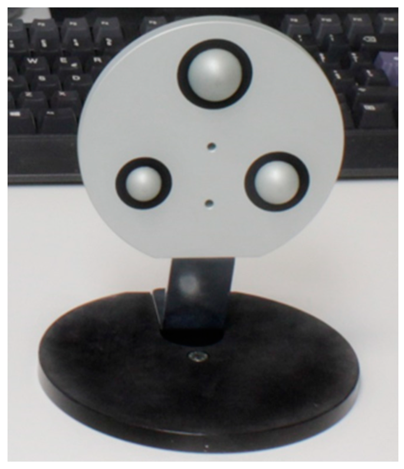
The first reference artifact (Figure 5) was an aluminum circular plate with three different semi-spheres on the upper surface. The reference phantom was coated with an opaque polish and the semi-spheres had a black contour in order to facilitate the center and diameter measurement. This artifact was measured with a contact coordinate measuring machine with an accuracy of 1.5 μm and certified by a metrology laboratory with a measuring extended uncertainty of 1.8 L/300 μm. The measured parameters were the three diameters of the spheres, their center-to-center distance, and their height. On the basis of these measured data, a 3D CAD model was drawn and used to assess the performance parameters.
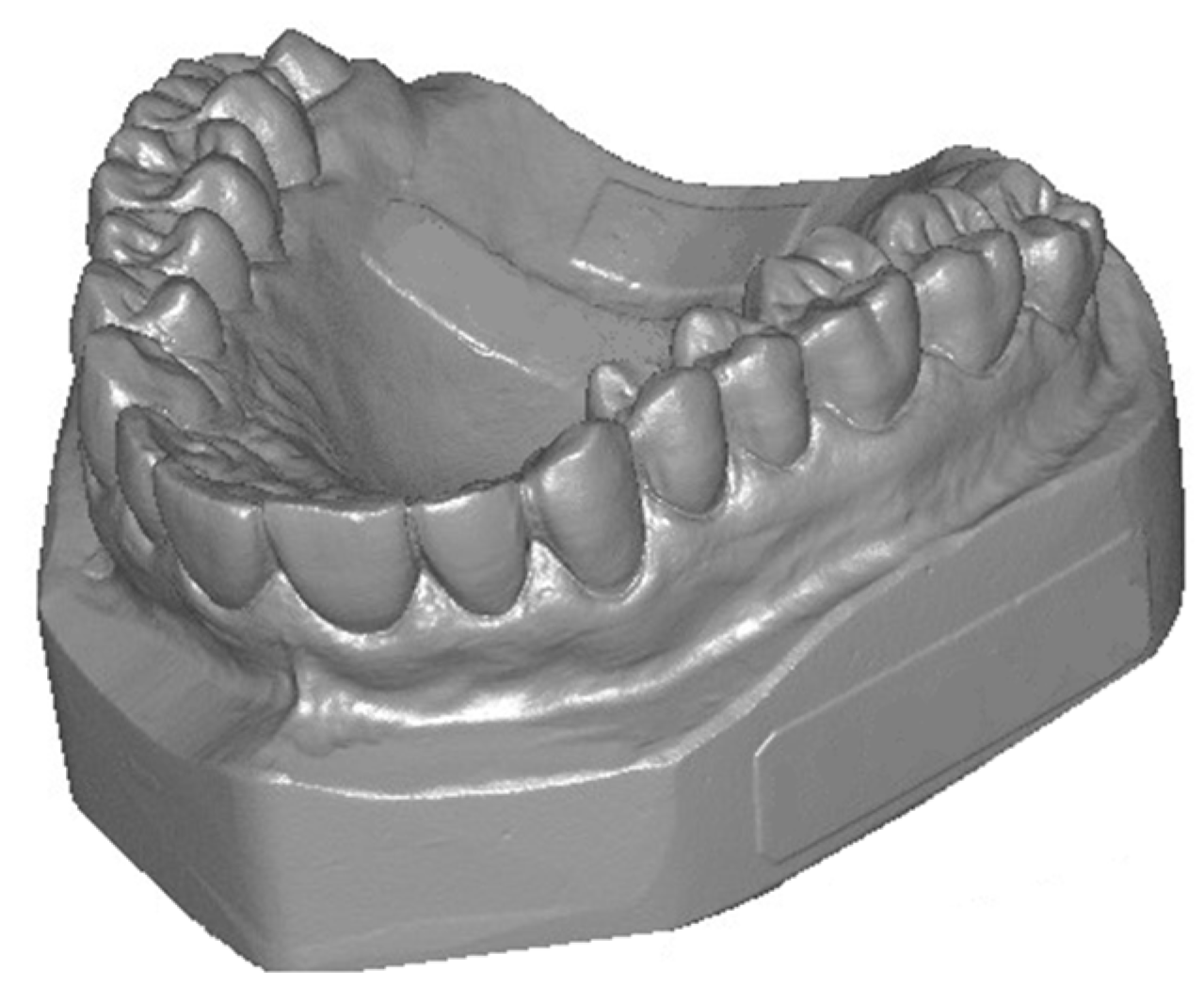
The second reference artifact (Figure 6) was a dental free-form white plaster model. This model was not measured and calibrated with a reference measuring machine and was just used to assess precision, repeatability, and reproducibility in small volumes.
The first experimental campaign was performed in a volume comprised between 133 × 100 × 100 mm3 and 300 × 225 × 225 mm3. According to Reference [32] (Part 3), the artifact with the three test spheres was moved in fifteen different arbitrary positions, by means of the tilt-rotational mechanical positioning system. By doing so, at least three different arbitrary sphere positions within the measuring volume were reached and also at least five different sensor positions with respect to each test sphere. Furthermore, the movements of the artifact were suitable to cover the whole scanning volume.
Single frame scans were used in order to compare the result with the reference CAD model. During this experimental campaign, the following parameters were measured: trueness and precision, both expressed in terms of the mean deviation of the points ± standard deviation.
The second experimental campaign was performed in a volume comprised between 66 × 50 × 50 mm3 and 133 × 100 × 100 mm3. According to the definitions in References [30,31], the parameters assessed with this experimentation were the repeatability and the reproducibility, based on the mean values on the 3D evaluations. The reference artifact was positioned on the mechanical positioning system in four different locations and directions within the scanning volume. For each position, a scanning session of eight rotations and three tilts was performed. After each session, four different merge procedures were performed with the same sampling and filtering parameters.
The repeatability was assessed by point by point comparing the four different 3D models obtained by the four merges at each position of the artifact within the scanning volume. By doing so, twelve comparisons were obtained and the repeatability was assessed in terms of the mean deviation of the points ± standard deviation.
The reproducibility was assessed by point by point comparing the 3D models obtained with the first merge at different positions of the artifact within the scanning volume.
Basically, for the repeatability assessment, the comparison was done between models in the same position within the target volume, while the reproducibility was assessed by comparing 3D models obtained in different positions of the artifact within the target volume. For this second experimental campaign, the full aligned and merged models were used.
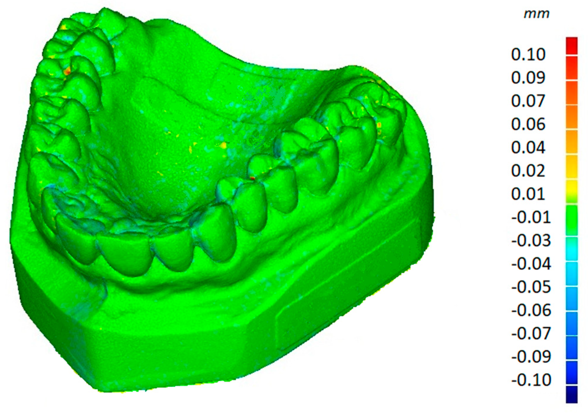
All the frame to frame alignments and merges during the scanning sessions were realized by the scanning software, while all the comparison mesh-to-mesh were done by using the software Geomagic Wrap 2015.1.1 (3D Systems, Inc., Rock Hill, SC, USA). All the experiments were carried out at 20 °C. Figure 7 shows the result of one of the repeatability evaluation tests of the second experimental campaign.
4. Results
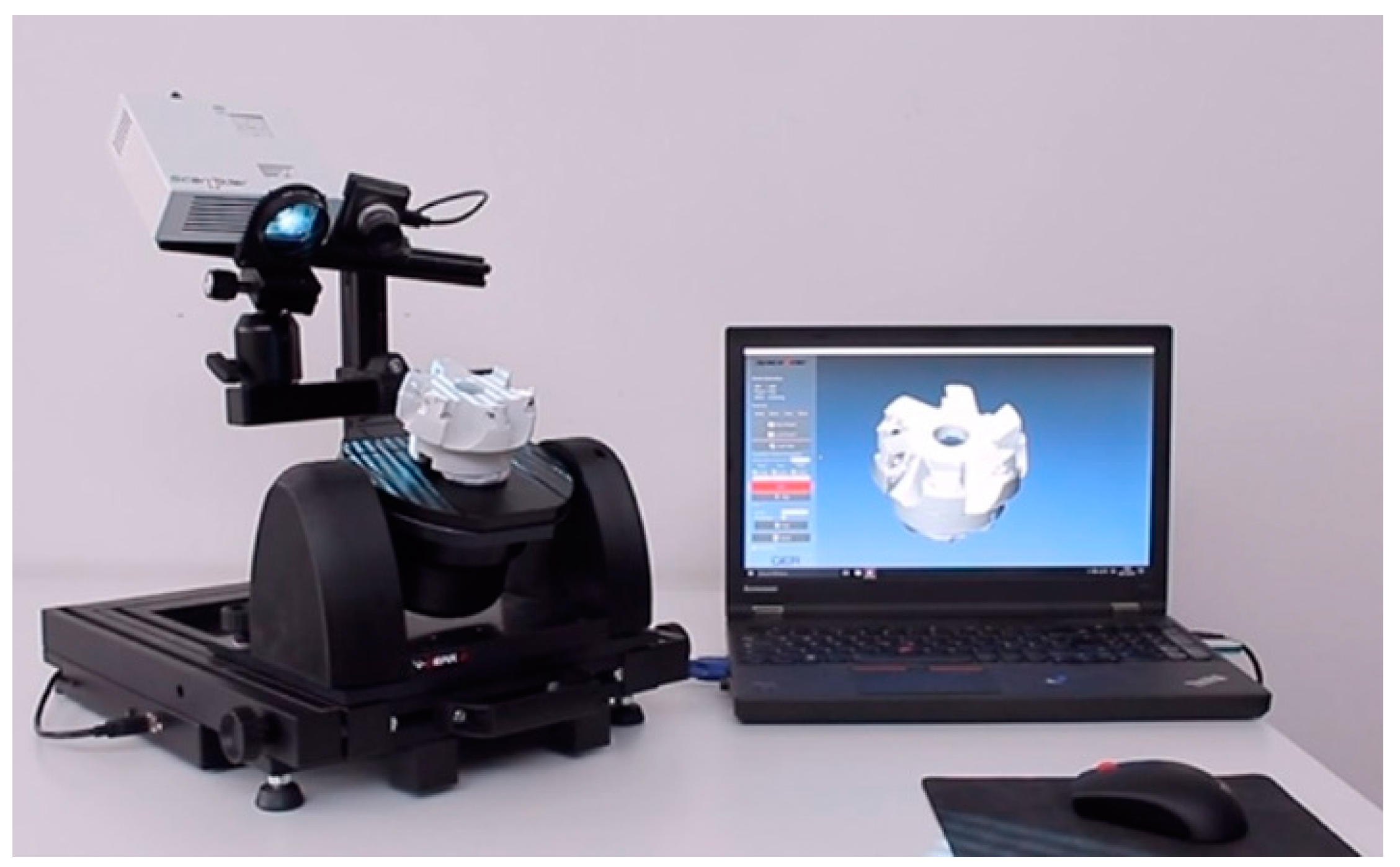
As a result of this research work, the first prototype of the scanning apparatus was built (Figure 8) and it was validated by means of the experimental campaigns.
The results of the first and second experimental campaigns for the evaluation of the performance parameters for different scanning volumes are represented in Table 1 and Table 2. Of course, these parameters need to be stabilized for different environmental conditions and different target surfaces.
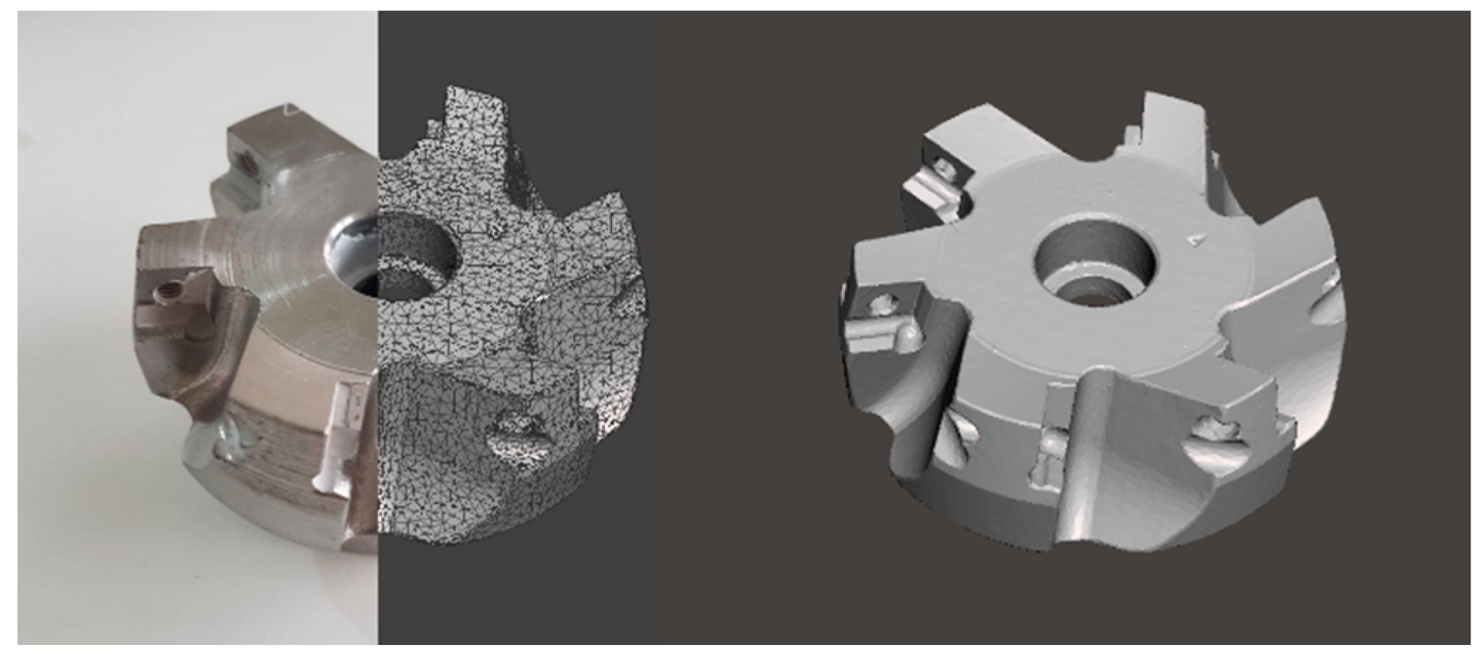
In Figure 9, an example of the result of a scanning procedure applied on a worn milling cutter is presented in terms of a polygonal 3D model. The first part of the picture (left side) represents both the real picture and the wireframe 3D model of the milling cutter; the second part (right side) represents the complete shaded polygonal 3D model as it results from the scanning session. The 3D model is a triangular mesh and the procedure was executed selecting a maximum scanning volume of 133 × 100 × 100 mm3 and 24 positions of the worktable.
5. Conclusions
The instrument proposed in this paper is a desktop automated 3D optical scanner with the aim of generating complete 3D reconstructions of objects of various sizes, especially for mechanical and medical purposes, but also for all the scanning applications involving objects from 5 mm to about 500 mm of the characteristic size. This is possible thanks to the flexible structure of the scanner, which has been studied and developed to be modular and adjustable for different purposes. In this paper, prior 3D scanning systems were analyzed, and the prototype of the device presented in this work has resulted to be innovative with respect to the state of the art of the desktop 3D scanners.
Furthermore, its performance parameters in terms of precision, repeatability, reproducibility, and trueness of the 3D data, suggest that the device can be advantageously used for applications where high detail and precision are required and especially for mechanical and medical small parts. Typical applications of this instrument are reverse engineering, development of industrial design, mechanical or medical components, surface analysis, wear, and deformation assessment.
6. Current & Future Developments
The current developments in the field of 3D scanning have been discussed in the first part of this paper. Future developments could be aimed to enhance the performance parameters of the optical scanners, in order to make them compete with the contact measuring machines. The device presented in this work will be surely enhanced by stabilizing its behavior in different environmental conditions and introducing different sensors to compensate for unwanted reflections.
Author Contributions
Conceptualization, S.L. and G.C.; Project administration, S.L., G.C.; Methodology, S.L., G.C. and M.C.V.; Software, G.C.; Validation, S.L.; Formal Analysis, S.L. and M.C.V.; Data Curation, S.L., M.C.V. and G.C.; Writing, S.L. and M.C.V.
Acknowledgments
Authors warmly acknowledge Andrea Mistro and Lorenzo Conti for their support.
Conflicts of Interest
The authors declare no conflict of interest.
References
- Son, S.; Park, H.; Lee, K.H. Automated laser scanning system for reverse engineering and inspection. Int. J. Mach. Tool. Manuf. 2002, 42, 889–897. [Google Scholar] [CrossRef]
- Chen, J.; Bautembach, D.; Izadi, S. Scalable real-time volumetric surface reconstruction. ACM Trans. Gr. 2013, 32, 113. [Google Scholar] [CrossRef]
- Affatato, S.; Valigi, M.C.; Logozzo, S. Wear distribution detection of knee joint prostheses by means of 3D optical scanners. Materials 2017, 10, 364. [Google Scholar] [CrossRef] [PubMed]
- Persson, A.; Andersson, M.; Oden, A.; Sandborgh-Englund, G. A three-dimensional evaluation of a laser scanner and a touch-probe scanner. J. Prosthet. Dent. 2006, 95, 194–200. [Google Scholar] [CrossRef] [PubMed]
- Jardini, A.L.; Larosa, M.A.; Filho, R.M.; de Carvalho Zavaglia, C.A.; Bernardes, L.F.; Lambert, C.S.; Calderoni, D.R.; Kharmandayan, P. Cranial reconstruction: 3D biomodel and custom-built implant created using additive manufacturing. J. Cranio-Maxillofac. Surg. 2014, 42, 1877–1884. [Google Scholar] [CrossRef] [PubMed]
- Hu, Z.; Marshall, C.; Bicker, R.; Taylor, P. Automatic surface roughing with 3D machine vision and cooperative robot control. Robot. Auton. Syst. 2007, 55, 552–560. [Google Scholar] [CrossRef]
- Dumitrache, A.; Borangiu, T.; Răileanu, S. Robotic 3D surface laser scanning for feature-based quality control in holonic manufacturing. Adv. Intell. Syst. and Comput. 2017, 540, 67–79. [Google Scholar] [CrossRef]
- Valigi, M.C.; Logozzo, S.; Affatato, S. New challenges in tribology: Wear assessment using 3D optical scanners. Materials 2017, 10, 548. [Google Scholar] [CrossRef] [PubMed]
- Valigi, M.C.; Logozzo, S.; Rinchi, M. Wear resistance of blades in planetary concrete mixers. Design of a new improved blade shape and 2D validation. Tribol. Int. 2016, 96, 191–201. [Google Scholar] [CrossRef]
- Valigi, M.C.; Logozzo, S.; Rinchi, M. Wear resistance of blades in planetary concrete mixers. Part II: 3D validation of a new mixing blade design and efficiency evaluation. Tribol. Int. 2016, 103, 37–44. [Google Scholar] [CrossRef]
- Valigi, M.C.; Logozzo, S.; Gasperini, I. Study of wear of planetary concrete mixer blades using a 3D optical scanner. In Proceedings of the International Mechanical Engineering Congress & Exposition (IMECE2015), Houston, TX, USA, 13–19 November 2015. [Google Scholar] [CrossRef]
- Valigi, M.C.; Fabi, L.; Gasperini, I. Wear resistance of new blade for planetary concrete mixer. In Proceedings of the 5th World Tribology Congress (WTC 2013), Turin, Italy, 8–13 September 2013; pp. 1208–1211. [Google Scholar]
- Szymor, P.; Kozakiewicz, M.; Olszewski, R. Accuracy of open-source software segmentation and paper-based printed three-dimensional models. J. Cranio-Maxillo-Fac. Surg. 2016, 44, 202–209. [Google Scholar] [CrossRef] [PubMed]
- Fioravanti, D.; Allotta, B.; Rindi, A. Image based visual servoing for robot positioning tasks. Meccanica 2008, 43, 291–305. [Google Scholar] [CrossRef]
- Huang, B.; Vandini, A.; Hu, Y.; Lee, S.L.; Yang, G.Z. A vision-guided dual arm sewing system for stent graft manufacturing. In Proceedings of the IEEE/RSJ International Conference on Intelligent Robots and Systems (IROS 2016), Daejeon, Korea, 9–14 October 2016. [Google Scholar] [CrossRef]
- Beyl, T.; Nicolai, P.; Comparetti, M.D.; Raczkowsky, J.; De Momi, E.; Wörn, H. Time-of-flight-assisted Kinect camera-based people detection for intuitive human robot cooperation in the surgical operating room. Int. J. Comput. Assist. Radiol. Surg. 2016, 11, 1329–1345. [Google Scholar] [CrossRef] [PubMed] [Green Version]
- Wu, Z.; Zhao, X.; Zhou, Z.; Wu, J.; Yu, H. Three Dimension Scanning System for Scanning Dynamic Object and Three Dimension Scanning Method for Scanning Dynamic Object. Patent CN102980511, 25 May 2016. [Google Scholar]
- Lee, S.B.; Chang, J.W.; Jang, K.J. Three Dimensional Measurement Apparatus for Dental Treatment. Patent KR20130013584, 6 February 2013. [Google Scholar]
- Kjær, R.; Højgaard, T.A.; Scherling, H. 3D Scanner Using a Structured Beam of Probe Light. Patent WO2017220786, 28 December 2017. [Google Scholar]
- Hollenbeck, K.J.; Jensen, S.E.; Højgaard, T.A.; Öjelund, H. 3D Scanner Using Merged Partial Images. U.S. Patent US2017307363, 26 October 2017. [Google Scholar]
- Chen, X.; Sun, J.; Xi, J.; Xiong, Y.; Qiu, J.; Gu, X. Development of a 3D optical measurement system based on fringe projection for facial prosthesis. In Proceedings of the IEEE Instrumentation and Measurement Technology Conference, Hangzhou, China, 9–12 May 2011; pp. 25–29. [Google Scholar] [CrossRef]
- Ding, W.; Zhu, X.; Huang, X. Effect of servo and geometric errors of tilting-rotary tables on volumetric errors in five-axis machine tools. Int. J. Mach. Tool. Manuf. 2016, 104, 37–44. [Google Scholar] [CrossRef]
- Dorosti, M.; Nobari, J.H. Kinematic and dynamic analysis of 3-DOF rotary table manipulator. In Proceedings of the Chinese Control and Decision Conference (CCDC 2009), Guilin, China, 17–19 June 2009; pp. 5745–5750. [Google Scholar] [CrossRef]
- Jywe, W.; Chen, C.J.; Hsieh, W.H.; Lin, P.D.; Jwo, H.H.; Yang, T.Y. A novel simple and low cost 4 degree of freedom angular indexing calibrating technique for a precision rotary table. Int. J. Mach. Tool. Manuf. 2007, 47, 1978–1987. [Google Scholar] [CrossRef]
- Taek, O.Y. Design of precision angular indexing system for calibration of rotary tables. J. Mech. Sci. Technol. 2012, 26, 847–855. [Google Scholar] [CrossRef]
- Valigi, M.C.; Logozzo, S.; Canella, G. A new automated 2 DOFs 3D desktop optical scanner. In Mechanisms and Machine Science; Springer: Cham, Switzerland, 2017; Volume 47, pp. 231–238. [Google Scholar]
- Tsai, R. A versatile camera calibration technique for high-accuracy 3D machine vision metrology using Off-the-shelf TV cameras and lenses. IEEE J. Robot. Autom. 1987, 3, 323–344. [Google Scholar] [CrossRef]
- Niola, V.; Rossi, C.; Savino, S. A new real time shape acquisition with a laser scanner: First test results. Robot. Comput. Integr. Manuf. 2010, 26, 543–550. [Google Scholar] [CrossRef] [Green Version]
- Genta, G.; Minetola, P.; Barbato, G. Calibration procedure for a laser triangulation scanner with uncertainty evaluation. Opt. Lasers Eng. 2016, 86, 11–19. [Google Scholar] [CrossRef]
- ISO/WD 5725:1994. Accuracy (Trueness and Precision) of Measurement Methods and Results: Part 1–6; ISO: Geneva, Switzerland, 1994.
- UNI EN ISO 12836:2015; ISO: Geneva, Switzerland, 2015.
- VDI/VDE 2634. Optical 3D Measuring Systems (Part 1–3); VDI: Düsseldorf, Germany, 2012.
Figure 1.
The 3D scanning apparatus and the framework’s degrees of freedom (DoFs). Numbers 1, 2 and 3 indicates the number of DoFs at each joint.
Figure 1.
The 3D scanning apparatus and the framework’s degrees of freedom (DoFs). Numbers 1, 2 and 3 indicates the number of DoFs at each joint.

Figure 2.
The optical assembly’s DoFs. Numbers 1 and 3 indicates the number of DoFs at each joint.

Figure 3.
The mechanical assembly DoFs.

Figure 4.
The optical alignment.

Figure 5.
First reference artifact.

Figure 6.
Second reference artifact.

Figure 7.
One of the repeatability tests.

Figure 8.
The prototype of the 3D scanning apparatus ScanRider while scanning a milling cutter.

Figure 9.
The resulting 3D polygonal model and picture of the milling cutter.


Table 1.
The results of the first experimental campaign.
| Scanning Volume Size (mm × mm × mm) | 133 × 100 × 100–300 × 225 × 225 |
|---|---|
| Resolution (mm) | ≤0.23 |
| Working distance (mm) | 520 |
| Mean standard deviation | 0.10 |
| Trueness and Precision (mm) | 0.03 ± 0.10 |
Table 2.
The results of the second experimental campaign.
| Scanning Volume Size (mm × mm × mm) | 66 × 50 × 50–133 × 100 × 100 |
|---|---|
| Resolution (mm) | ≤0.1 |
| Working distance (mm) | 200 |
| Mean standard deviation for repeatability (mm) | 0.024 |
| Repeatability (mm) | 0.015 ± 0.024 |
| Mean standard deviation for reproducibility (mm) | 0.031 |
| Reproducibility (mm) | 0.011 ± 0.031 |
© 2018 by the authors. Licensee MDPI, Basel, Switzerland. This article is an open access article distributed under the terms and conditions of the Creative Commons Attribution (CC BY) license (http://creativecommons.org/licenses/by/4.0/).
Share and Cite
MDPI and ACS Style
Logozzo, S.; Valigi, M.C.; Canella, G. Advances in Optomechatronics: An Automated Tilt-Rotational 3D Scanner for High-Quality Reconstructions. Photonics 2018, 5, 42. https://0-doi-org.brum.beds.ac.uk/10.3390/photonics5040042
AMA Style
Logozzo S, Valigi MC, Canella G. Advances in Optomechatronics: An Automated Tilt-Rotational 3D Scanner for High-Quality Reconstructions. Photonics. 2018; 5(4):42. https://0-doi-org.brum.beds.ac.uk/10.3390/photonics5040042
Chicago/Turabian StyleLogozzo, Silvia, Maria Cristina Valigi, and Gabriele Canella. 2018. "Advances in Optomechatronics: An Automated Tilt-Rotational 3D Scanner for High-Quality Reconstructions" Photonics 5, no. 4: 42. https://0-doi-org.brum.beds.ac.uk/10.3390/photonics5040042
Note that from the first issue of 2016, this journal uses article numbers instead of page numbers. See further details here.