Article

High-Precision Time-Frequency Signal Simultaneous Transfer System via a WDM-Based Fiber Link

1
National Time Service Center, Chinese Academy of Sciences, 3 Shuyuandong Road, Xi’an 710600, China
2
Key Laboratory of Time and Frequency Primary Standards, Chinese Academy of Sciences, 3 Shuyuandong Road, Xi’an 710600, China
3
University of Chinese Academy of Sciences, 19 Yuquan Road, Beijing 100049, China
4
State Key Laboratory of Transient Optics and Photonics, Chinese Academy of Sciences, Xinxi Road, Xi’an 710119, China
5
School of Aerospace Science and Technology, Xidian University, 2 Taibainan Road, Xi’an 710071, China
*
Author to whom correspondence should be addressed.
Submission received: 7 July 2021 / Revised: 29 July 2021 / Accepted: 9 August 2021 / Published: 10 August 2021
(This article belongs to the Special Issue Optical Network and Access Technologies)

Abstract

:
In this paper, we demonstrate a wavelength division multiplexing (WDM)-based system for simultaneously delivering ultra-stable optical frequency reference, 10 GHz microwave frequency reference, and a one pulse per second (1 PPS) time signal via a 50 km fiber network. For each signal, a unique noise cancellation technique is used to maintain their precision. After being compensated, the transfer frequency instability in terms of the overlapping Allan deviation (OADEV) for the optical frequency achieves 2 × 10 17 /s and scales down to 2 × 10 20 /10,000 s, which for the 10 GHz microwave reference, approaches 4 × 10 15 /s and decreases to 1.4 × 10 17 /10,000 s, and the time uncertainty of the 1 PPS time signal along the system is 2.08 ps. In this scheme, specific channels of WDM are, respectively, occupied for different signals to avoid the possible crosstalk interference effect between the transmitted reference signals. To estimate the performance of the above scheme, which is also demonstrated in this 50 km link independent of these signals, the results are similar to that in the case of simultaneous delivery. This work shows that the WDM-based system is a promising method for building a nationwide time and frequency fiber transfer system with a communication optical network.

1. Introduction

With the rapid development of the modern timescales and frequency domain, the frequency instability of the state-of-the-art optical lattice clocks has achieved the 10 19 level, and 10 16 has been demonstrated for the cesium fountain [1,2,3,4,5,6,7]. Optical lattice clocks are widely used in many advanced scientific and industrial applications such as geodesy, test of fundamental constants, precision navigation, time keeping, and astronomy [8,9,10,11,12,13].
Unfortunately, the ultra-precision timescale and frequency signal are affirmatively derived from cumbersome and expensive systems, which are normally placed at national metrology institutes or universities. The status causes a strong motivation to develop effective dissemination systems for distributing these super-precise time and frequency signals. Among the existing schemes, the optical fiber is regrading as an ideal transmission medium because of its advantages of low power attenuation, high reliability, lower cost, and large communication capacity, which has been fleetly and widely deployed for time and frequency transfer [14,15,16,17]. Furthermore, with it, various transmission techniques for the above-mentioned metrological time and frequency signal are rapidly developing alternatives. For the optical frequency reference, an additional phase noise induced by the variation of fiber physical length and the refractive index induced as a result of vibration and temperature fluctuation will deteriorate instability. To cancel the so-called Doppler noise, the active noise cancellation scheme was first proposed and implemented by Ma et al. in 1994, by which the phase error between the local refer signal and the round-trip optical signal is derived and further feedback to the voltage-controlled oscillators [18]. For the timescale signal, Steven R. Jefferts et al. came up with the two-way time transfer technique using optical fibers in 1996, which allowed a time transfer over short distances (km) with stabilities less than 10 ps [19], then various techniques to acquire the delay fluctuation and to compensate for it in the fiber [20,21,22]. Additionally, a dissemination system for the ultra-stable 100 MHz microwave frequency signal along a standard fiber network has been demonstrated by F. Narbonneau et al. using amplitude modulation of an optical carrier [23].
For some scientific researchers, there is a pressing need for the simultaneous dissemination of time and frequency signals, such as VLBI, and further redefinition of the second et al. [24,25]. In order to meet this demand, several kinds of schemes are proposed to simultaneously transfer the time and frequency signals over a single long-haul fiber link [26,27]. The most possible and convenient solution is to combine the time and frequency signals by using a wavelength-division multiplexing (WDM)-based fiber network. In [28], the authors demonstrated an optical frequency reference transfer compatible with data traffic using the internet fiber network with the WDM technique. Ukasz liwczyski et al. observed very good stability of two delivered signals in a WDM transfer link: the Allan deviation approach 4 × 10 17 (for 10 MHz frequency signal) and a time deviation below 1 ps for one pulse per second (1 PPS) time signal, both at a one-day averaging time in 2013 [21]. Ref [20] also shows an 80 km WDM fiber link synchronization system for two references (time and 9.1 GHz microwave frequency) at the 5 × 10 19 accuracy level of the frequency and 50 ps precision level of the time. Besides, the time and frequency simultaneous transfer research through fiber optics links has been demonstrated in recent years, and there are very meaningful results [26,29,30,31,32,33]. Up to now, the familiar simultaneous transfer of time and frequency references based on the WDM system focuses on signals time-microwave or time-optical frequency. Taking into account the multiple needs and the flexible diversity of options for remote users, the WDM-based solution for offering the common reference signals (time and microwave frequency) and the most precise optical frequency reference at the same time has become important and necessary.
In this work, we present a simultaneous transfer of the optical frequency, 10 GHz microwave frequency, and 1 PPS time signal via a WDM-based fiber link. Moreover, we use the active noise cancellation method and electronic phase compensation technique to compensate the fiber noise for optical and 10 GHz microwave frequency signals, respectively, while the dual-wavelength time synchronization technique is applied for the 1 PPS time signal. We observe a relative frequency instability of 3 × 10 19 for optical frequency and 1.4 × 10 17 at 10,000 s for 10 GHz microwave frequency, both at a 10,000 s integration time, and the uncertainty of the 1 PPS is 2.08 ps. Note that the time and frequency signals are all generated from the National Time Service Center (NTSC) lab, and the three transfer systems are synchronized using the same standard timebase. This technique provides a flexibly and freely chosen metrology time and frequency signal for remote users.

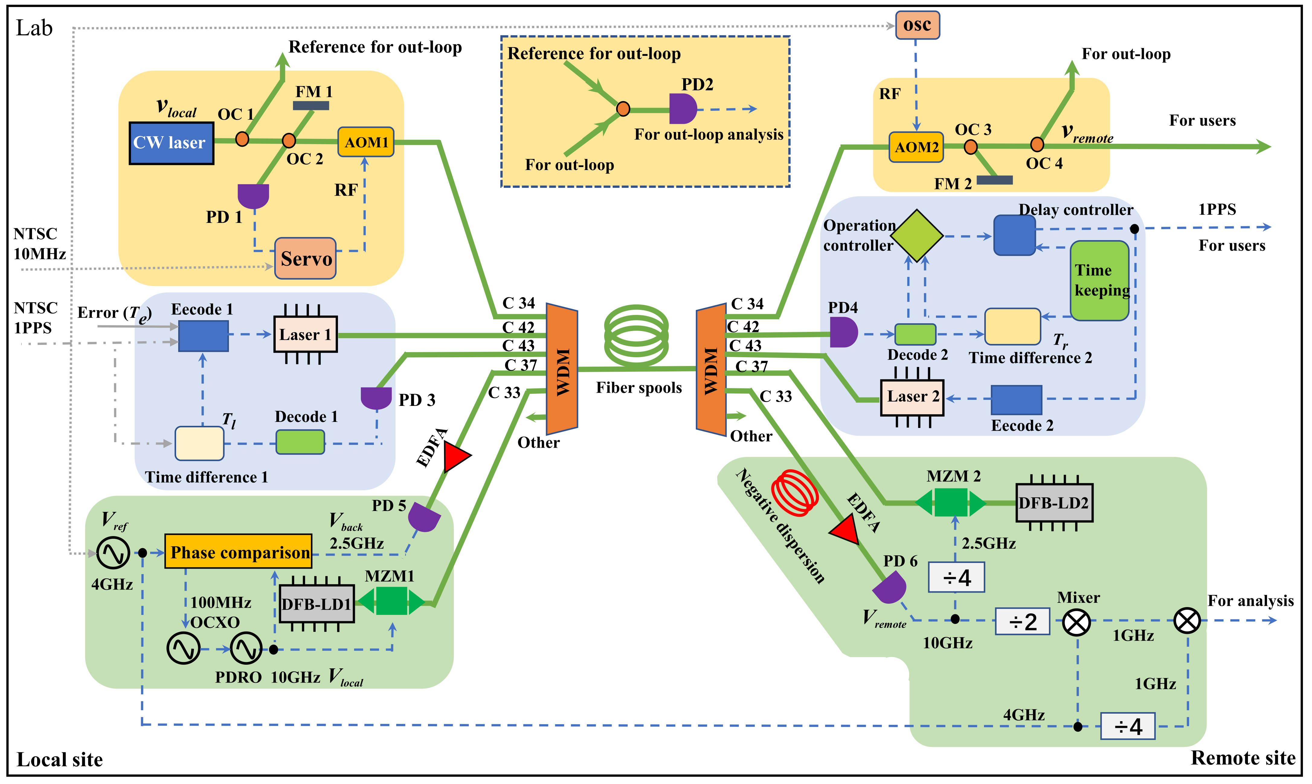
2. The Scheme of the WDM-Based System

The main schematic diagram of the WDM-based system is shown in Figure 1. The bandwidth of every channel in the WDM is about 100 GHz (0.8 nm) with an isolation ratio of 50 dB, and the insert loss is 1 dB. In this setup, the optical frequency signal travels in the C 34 channel, the 10 GHz microwave frequency goes in the C 33 channel on the uplink and goes in the C 37 channel on the downlink, and the 1 PPS time signal uses C 42 and C 43 channels for the remote time synchronization. Otherwise, the other channel can be used as an extension path for other communications services. In the local site of this scheme, the five specific wavelengths carrying different time or frequency signals are combined into the WDM for traveling in the fiber link. At the remote site, another WDM is used as a de-wave division device to distinguish different signals into their respective channels for each transfer system and to evaluate the measurement results. All the above-mentioned setups are placed in the NTSC laboratory, and a 50 km spooled fiber link is employed in this experiment. The major reason that we employ the 50 km fiber spool is that the commercial typical length of the fiber spool is 50 km, and it has the typical attenuation of 10 dB. The 50 km is not the minimum length; it can be reduced or extended. For this transfer system, the minimum length can be as short as several tens of centimeters, while an additional attenuator is needed to avoid the saturation of the photodetector. The transfer distance can also be extended to several hundred kilometers or even thousand kilometers with proper optical amplifiers, such as EDFA, FBA, or regenerative amplifiers, though nonlinear optical scattering may enhance with the increase in the number of amplifiers, which may influence the transfer precision and should be carefully investigated. Note that a dispersion compensation fiber is placed at the output port of the C 33 channel, which is used to compensate the mode dispersion of the 10 GHz microwave frequency reference with an additional insertion loss of 5 dB.
For a coherent optical frequency transfer link (marked on Figure 1 with a yellow background color), the Doppler noise suppression method is used to actively eliminate noise induced by the transmission link to realize the local ultra-stable optical frequency signal copied at the remote site [34]. The carrier laser source is an ultra-stable continuous-wave (CW) with a linewidth of 1.9 Hz, in which the center wavelength is 1550.12 nm [35]. The frequency of the laser output laser υ l o c a l is expressed as
υ l o c a l = d ϕ 0 ( t ) d t ,
where the ϕ 0 ( t ) is the initial phase of CW laser. The laser is split into two parts by a 90/10 optical coupler (OC1); the 90% part is injected into fiber for transfer, while the 10% part is used as reference light for an out-loop evaluation of the transmission quality. Then, the 90% transferred light is split into two parts by the 50/50 OC2; one part is directly reflected in the photodetector (PD1) by a Faraday mirror 1 (FM1), and the other part passes through the acoustic-optical modulator 1 (AOM1). Furthermore, the transmitted signal goes into the C 34 channel of WDM for transmission in the fiber. Here, the AOM1 shifts the optical frequency signal with 110 MHz and acts as a noise cancellation device. On the remote side, the optical frequency light transfers out from the WDM and passes the AOM2. Then, the light is further split into two parts again by OC3; the larger part is returned to the PD1 by FM2, while the smaller part is used for the evaluation of the transfer performance, expressed as
υ r e m o t e = υ l o c a l + d [ ϕ c ( t τ ) + ϕ t r a n s f e r ] d t ,
where the ϕ c ( t τ ) is the compensation phase, τ is the single-trip time, and ϕ t r a n s f e r is the transfer phase. Because of the swirling effect of the Faraday mirror, the reference signal and returned signal have the same polarization state to generate a stable beat note signal at PD1. We extract the error signal from the beat note signal and use it to compensate the fiber noise through the AOM1. Then, the υ r e m o t e is transformed into
υ r e m o t e d ϕ 0 ( t ) d t .
The AOM2 helps to discriminate the return light from the stray reflections by splices and connectors, which shift the optical frequency of 50 MHz. PD2 is used to characterize and analyze the performance of out-loop instability. For reducing impact on the environment, the mismatch fiber length of the interferometer is designed to be as short as possible. The mismatched part of the interferometer is mainly due to the mismatch of the length of the out-loop part (see Figure 1 dash line little window). In this part, the noise from the environment can not be compensated, and it will dominate the performance of the optical frequency transfer system. This kind of mismatch is inevitable in the experiment, so we designed this part of the fiber as short as possible to reduce the impact on the environment. In our system, we use a fiber fusion splicer to reduce the mismatch part of the fiber be as short as possible. However, the transfer link between local and remote sites belongs to the symmetrical link in the interferometer that can be compensated.
The C 42 channel and C 43 channel are used to transfer the the 1 PPS time signal. For the 1 PPS time dual-wavelength synchronization transfer, there are also local sites and remote sites in the system, as shown in Figure 1 (marked with a blue background color). The 1 PPS signal from NTSC in the local site is modulated to laser 1 (center wavelength is 1543.7 nm) by the encoder1, then the light travels in the C 42 channel to the remote site. The signal is detected by PD4 and decoded for fiber dispersion delay information, then sent to the operation controller. The incoming 1 PPS time signal is compared with the timekeeping 1 PPS signal of remote site module by a time difference measurement module 2. This time difference signal T r is also sent to the operation controller. The operation controller processes the time difference and error data T e caused by fiber dispersion, then uses the delay controller to adjust the 1 PPS signal output by the timekeeping module. The 1 PPS time signal of the remote site is modulated to laser 2 (center wavelength is 1542.9 nm) by the encoder2 and travels in the C 43 channel back to the local site. The back signal is detected by PD3 and decoded by decode 1, and then the signal is fed to the time difference module 1 for comparison with the 1 PPS time in the local site. Timekeeping in the remote site has two functions. When the fiber transfer link is working, timekeeping is responsible for producing the time difference information Tr with the transferred 1 PPS to the operation controller, then the signal from the delay controller is fed to the 1 PPS signal. When the fiber link is disconnected, timekeeping continuously launches the 1 PPS signal to ensure that the signal will not be interrupted. Notice here that the operation controller will export a fixed value before the fiber link is broken. In our experiment, the timekeeping is a Rubidium Module (SRS PRS10), which has a precision of about 10 ns. According to this scheme, the time delay compensation control amount T d of dual-wavelength time synchronization can be expressed as
T d = 1 2 ( T l T r ) + T s + T e .
where the T l and T r are measured by the time difference measurement module of the local and remote site. T s is the system delays and can be calibrated in the equipment. We define this time delay to T s as the constants for our 1 PPS time signal transfer system. The T s measurement method is shown in Figure 2. Firstly, the 1 PPS time signal is split into two parts. One goes through cable 1 ( l 1 ) to the time interval counter (TIC). Another one goes through cables 2 and 3 ( l 2 and l 3 ) to the TIC. The T s 1 is the time delay of these cables and a reference time delay. Secondly, we install our time transfer system between l 2 and l 3 to measure the T s 2 . Then, the Ts can be calculated as T s = T s 1 T s 2 . Here, the TIC is from Stanford research SR620.
T e is the time delay caused by the fiber dispersion, and T e can be calculated by
T e = 1 2 D ( λ 1 λ 2 ) L ,
where D is the dispersion coefficient, λ is the laser wavelength, and L is the fiber length.
In the 10 GHz microwave frequency transfer link, there are also local and remote ends located in our laboratory (marked on Figure 1 with a green background color). The reference frequency V r e f is 4 GHz generated by an RF source (Keysight E8257D), which is synchronized with the NTSC 10 MHz timebase, expressed as
V r e f sin ( ω r t + ϕ r ) ,
where ϕ r is the initial phase of the V r e f . At the local site, the transferred 10 GHz microwave frequency V l o c a l is generated from a phase-locked resonant oscillator (PDRO), which is locked to a low noise 100 MHz oven-controlled crystal oscillator (OCXO). At the remote site, the transferred 10 GHz microwave frequency V r e m o t e is detected by PD6 and then is divided into 2.5 GHz by a frequency divider. This 2.5 GHz signal is used as the backward signal. The intensity of the distributed feedback laser diode (DFB-LD) at 1547.7 nm for the forward link and 1550.9 nm for the backward link are modulated by forward and backward microwave frequency signals with the Mach–Zehnder modulator (MZM), respectively. Hence, the forward signal travels in the C 37 channel and the backward signal travels in the C 33 channel. The 2.5 GHz backward signal is detected by PD5 at the local site, and the signal V b a c k carries the roundtrip noise over the fiber link. Based on V r e m o t e , V r e f , and V b a c k , the phase comparison system gives the error control signal, which is fed to 100 MHz OCXO to cancel the fiber link noise. Then, the V l o c a l is transformed and expressed as
V l o c a l sin ( 5 2 ω r t + 5 2 ϕ r + ω 0 τ ) ,
where τ is the one-way trip propagation delay of fiber. Furthermore, the V r e m o t e is
V r e m o t e sin 5 2 ( ω r t + ϕ r ) .
The effect of the chromatic dispersion in the fiber will deteriorate microwave frequency transmission performance over the link. To reduce the effect of the chromatic dispersion (17 ps/nm·km) of fiber link on the microwave frequency transfer, a large negative dispersion fiber (−950 ps/nm) is set in the microwave frequency transfer system. In this experiment, due to the experimental conditions, we only have the negative dispersion fiber (−950 ps/nm). However, this will not affect our test performance according to our experiment results.

3. The Experimental Results and Discussion

To evaluate the performance of this WDM-based time and frequency transfer system, the results are performed in three parts: the optical frequency transfer, the 1 PPS time signal transmission, and the 10 GHz microwave frequency transfer.

3.1. Optical Frequency Transfer

The phase noise PSD of the optical frequency transfer link is measured with a fast Fourier transform spectrum analyzer (Stanford Research System, SR785), as shown in Figure 3a. The red line is the free-running link, and it exhibits a relationship with the frequency as 100 / f 2 in the 0.1–1000 Hz [36] (the green dash line in Figure 3a), which indicates a white phase noise disturbance along the fiber link. The blue line is the phase noise of the compensated link, and it has more than five orders below than free-running link at 1 Hz. The higher peak in 600 Hz is caused by the servo control bandwidth limit of 1/4 τ [36]. According to the theoretical noise reduction ratio 1 / 3 ( 2 π τ f ) 2 , with f being the Fourier frequency and τ being the single-trip delay time [36,37], the corresponding residual phase noise is calculated as shown by the gray line. The phase noise of the stabilized link is coincident with the gray line, which illustrates that the loop control bandwidth is the main factor limiting the system’s performance.
For the coherence optical frequency transfer system, a no-dead-time frequency counter (FXE K+K) is employed to record the out-loop beat-notes detected by PD2 (see Figure 1 dash line little window), with a gate time of 1 s operating in Λ -type mode. The fractional instabilities of the optical frequency with and without compensation are shown in Figure 3b. For the free-running link, the overlapping Allan deviation is 3.5 × 10 15 at 1 s averaging time and and decrease to 9.2 × 10 15 at 4000 s averaging time. When the phase noise is canceled, the overlapping Allan deviation with the black square line is 1.8 × 10 17 at 1 s averaging time and scales down as 1/ τ slop to 3 × 10 19 at 10,000 s averaging time. The modified Allan deviation (the red dot line) is also calculated, and the 1 s instability is the same as the overlapping mode, while it reaches 9 × 10 20 at the 10,000 s averaging time.

3.2. 1 PPS Time Signal Transfer

In order to test the performance of the 1 PPS time signal transfer through C 42 and C 43 channels in the WDM-based system, the transmitted 1 PPS time signal and the local reference 1 PPS are compared.
When the local site and remote site are working properly, the 1 PPS signal from remote site output and the reference 1 PPS are compared by a time difference measure device (SR620) with a gate time of 1 s. In our experiment, there is a display screen to monitor the working status of the local and remote sites of the 1 PPS time signal transfer, including the temperature and humidity stabilized near the control point and the time difference data span within the expected range, etc.
During the test, the errors and time delays in the system, such as dispersion error and time delay of the difference in cable length, have been calibrated by the time transfer equipment. Figure 4a shows the time difference data in one day (the green dots), in which the peak-to-peak is about 70 ps, the time uncertainty is calculated to be 2.08 ps, and the time data follows the Gauss fit (the red line in Figure 4b).
At the same time, the time synchronization results of the 1 PPS time signal are shown as a time deviation (TDEV) in Figure 4c. It can be found that the TDEV is 7.06 × 10 12 at a 1 s integration time, reaching 3.75 × 10 13 at a 10,000 s integration time (the red dot line). Because of the temperature fluctuation by the air conditioner in the lab (approximately 16 min as a cycle) and the wavelength shift of the lasers, the long-term time instability at 200 s deteriorate in the curve. The temperature range is about 3–4 °C by the air conditioner in the lab, and the physical dimension of the system is a 3U chassis (19 inch). Meanwhile, the reason the TDEV at a 10,000 s integration time is higher than the previous data point is the long-term temperature drift of the internal circuit board of the 1PPS time signal transfer equipment.

3.3. 10 GHz Microwave Frequency Transfer

For evaluating the performance of the 10 GHz microwave frequency transfer in the WDM-based system, we measured the phase difference between the local reference signal V r e f and the received signal V r e m o t e in the locked loop (see Figure 1). The phase difference of V r e f and V r e m o t e is down-converted to direct current (DC) voltage V t r a n s f e r and measured by a multimeter (Keysight 3458A). Figure 5a shows the phase noise of the microwave frequency transfer link at 10 GHz. The red curve is the free-running link measured by mixing V l o c a l and V r e m o t e . The blue curve represents the compensated link phase noise obtained by measuring the V t r a n s f e r . The peak of the compensated link at about 600 Hz is the servo bandwidth of the 10 GHz microwave frequency transfer, which agrees with Ref. [36]. Here, the servo bandwidth is only available when the compensation system (Phase Lock Loop) is working. The servo bandwidth of the phase noise correction is limited by the fiber propagation delay with 600 Hz ( f = 1/4 τ ), which is characterized as a strong bump in the compensated link curve, and τ is the single trip transmission delay of the fiber length L = 50 km. However, when the link is free running, the phase lock loop is not working, and the phase noise curve will have no bump at 600 Hz. At the same time, because there is no servo bandwidth, the phase noise will not accumulate at 600 Hz, and the PSD is lower than the compensated link. The same situation also occurs in the optical frequency transfer system, as Figure 3a showed. It can be analyzed from the phase noise curves that the noise has been canceled 30 dB in 1 Hz by locking the transfer link.
Figure 5b shows the instability of the 10 GHz microwave frequency calculated from the link delay of the free-running and compensated link. The instabilities of overlapping the Allan deviation, as shown by the red dot curve, are 4.0 × 10 15 at a 1 s integration time and 1.4 × 10 17 at a 10,000 s integration time. A blue dot curve also shows the modified Allan deviation of the stabilized link, which achieves 4.0 × 10 15 at a 1 s integration time and decreases to 5.5 × 10 18 at a 10,000 s integration time. The black dot line is plotted to the uncompensated link in comparison with the compensated link. At the same time, the system floor of the 1 m compensated link is shown in the figure as a comparison with the pink dot curve. It can be found that there are bumps in these ADEV curves, which is also because the temperature disturbances in the laboratory by the air conditioner.

3.4. Simultaneous and Independent Transfer Comparison

For comparing the performance of the WDM-based simultaneous transfer system with independent transfer via the link, an independent experiment of these time and frequency signals transfers is also demonstrated in this link. In the experiment, the individual measurement of a specific system is evaluated by blocking the signal from other channels to ensure that there is only one signal in the transfer link.
For different fiber links, the noise situations are different. In Table 1, we aim to compare the simultaneous transfer and independent transfer. The comparison results are shown in Table 1 (ST refers to simultaneous transfer, and IT refers to independent transfer). Here, the overlapping ADEV is used to characterize the transfer performance of the optical frequency and the 10 GHz microwave frequency, while the 1 PPS time signal is expressed by uncertainty. For the optical frequency signal, the short-term (1 s) simultaneous and independent transfers are 2.12 × 10 17 and 2.15 × 10 17 , while the long-term transfers (4000 s) are 2.62 × 10 20 and 2.18 × 10 20 . The transfer results in the two cases are almost equal. The same situation also occurs in the 10 GHz microwave frequency and the 1 PPS time signal. The WDM-based simultaneous transfer system has shown a similar performance compared to the independent transmission system, which proves its usefulness and capability in time and frequency related applications. However, when the optical amplifiers are added to the link in order to amplify the signals, there will be new problems, such as the distribution of signal gain and influence between channels, etc., which will be our future investigation.

4. Conclusions

In summary, we demonstrate a WDM-based system for the simultaneous transfer of the optical frequency, 10 GHz microwave frequency, and 1 PPS time signal over a 50 km spooled fiber link, which are synchronized with the national standard time or frequency from NTSC. The solution, combining three systems into one fiber, allows the users to choose any reference signals according to their application scenarios. Additionally, the WDM-based system can be flexibly integrated with the existing communication network without the need of a dedicated optical fiber. After being compensated, the fractional frequency instability of optical frequency is 1.8 × 10 17 at 1 s and 3 × 10 19 at 10,000 s integration times, and 4 × 10 15 at a 1 s integration time and 1.4 × 10 17 at 10,000 s for 10 GHz microwave frequency transfer. For 1 PPS time signal transfer, the uncertainty is calculated to be 2.08 ps and the instability is 7.06 ps at a 1 s averaging time. These results show the WDM-based system has great potential for the time and frequency transfer with a commercial fiber link, so as to save costs and realize nationwide time and frequency transmission in the future.
In the next work, we are planning to conduct longer-distance transmission with bidirectional Erbium-doped optical amplifiers in communication fibers. For testing and improving the system reliability, it is also necessary to study interference between channels and the gain distribution of optical amplifiers.

Author Contributions

Conceptualization, Q.Z., T.L. and R.D.; Data curation, H.Q. and K.Z.; Formal analysis, Q.Z., X.Z. and X.D.; Funding acquisition, T.L.; Methodology, Q.Z. and R.D.; Software, W.X. and F.C.; Supervision, S.Z. All authors have read and agreed to the published version of the manuscript.

Funding

The Strategic Priority Research Program of the Chinese Academy of Sciences (Grant No. XDB21000000) and the Open Project Fund of State Key Laboratory of Transient Optics and Photonics, Chinese Academy of Sciences (Gtant No. SKLST202011).

Acknowledgments

The authors would like to thank W. Zhao for technical assistance.

Conflicts of Interest

The authors declare no conflict of interest.

References

  1. Chou, C.W.; Hume, D.B.; Koelemeij, J.C.J.; Wineland, D.J.; Rosenband, T. Frequency Comparison of Two High-Accuracy Al+ Optical Clocks. Phys. Rev. Lett. 2010, 104, 070802. [Google Scholar] [CrossRef] [PubMed] [Green Version]
  2. Hinkley, N.; Sherman, J.A.; Phillips, N.B.; Schioppo, M.; Lemke, N.D.; Beloy, K.; Pizzocaro, M.; Oates, C.W.; Ludlow, A.D. An Atomic Clock with 10(-18) Instability. Science 2013, 341, 1215–1218. [Google Scholar] [CrossRef] [Green Version]
  3. Bloom, B.J.; Nicholson, T.L.; Williams, J.R.; Campbell, S.L.; Bishof, M.; Zhang, X.; Zhang, W.; Bromley, S.L.; Ye, J. An optical lattice clock with accuracy and stability at the 10(-18) level. Nature 2014, 506, 71. [Google Scholar] [CrossRef] [PubMed] [Green Version]
  4. Ushijima, I.; Takamoto, M.; Das, M.; Ohkubo, T.; Katori, H. Cryogenic optical lattice clocks. Nat. Photonics 2015, 9, 185–189. [Google Scholar] [CrossRef]
  5. Beloy, K.; Safronova, U.I.; Derevianko, A. High-accuracy calculation of the blackbody radiation shift in the Cs-133 primary frequency standard. Phys. Rev. Lett. 2006, 97, 040801. [Google Scholar] [CrossRef] [Green Version]
  6. Raupach, S.M.F.; Koczwara, A.; Grosche, G. Brillouin amplification supports 1×10-20 uncertainty in optical frequency transfer over 1400 km of underground fiber. Phys. Rev. A 2015, 92, 021801. [Google Scholar] [CrossRef] [Green Version]
  7. Weyers, S.; Gerginov, V.; Kazda, M.; Rahm, J.; Lipphardt, B.; Dobrev, G.; Gibble, K. Advances in the accuracy, stability, and reliability of the PTB primary fountain clocks. Metrologia 2018, 55, 789–805. [Google Scholar] [CrossRef] [Green Version]
  8. Foreman, S.M.; Holman, K.W.; Hudson, D.D.; Jones, D.J.; Ye, J. Remote transfer of ultrastable frequency references via fiber networks. Rev. Sci. Instrum. 2007, 78, 021101. [Google Scholar] [CrossRef] [Green Version]
  9. Riehle, F. Towards a redefinition of the second based on optical atomic clocks. C. R. Phys. 2015, 16, 506–515. [Google Scholar] [CrossRef] [Green Version]
  10. Clivati, C.; Ambrosini, R.; Artz, T.; Bertarini, A.; Bortolotti, C.; Frittelli, M.; Levi, F.; Mura, A.; Maccaferri, G.; Nanni, M.; et al. A VLBI experiment using a remote atomic clock via a coherent fibre link. Sci. Rep. 2017, 7, 1–8. [Google Scholar] [CrossRef] [PubMed] [Green Version]
  11. He, Y.; Baldwin, K.G.H.; Orr, B.J.; Warrington, R.B.; Wouters, M.J.; Luiten, A.N.; Mirtschin, P.; Tzioumis, T.; Phillips, C.; Stevens, J.; et al. Long-distance telecom-fiber transfer of a radio-frequency reference for radio astronomy. Optica 2018, 5, 138–146. [Google Scholar] [CrossRef] [Green Version]
  12. Lisdat, C.; Grosche, G.; Quintin, N.; Shi, C.; Raupach, S.M.F.; Grebing, C.; Nicolodi, D.; Stefani, F.; Al-Masoudi, A.; Doerscher, S.; et al. A clock network for geodesy and fundamental science. Nat. Commun. 2016, 7, 1–7. [Google Scholar] [CrossRef] [PubMed]
  13. Dierikx, E.F.; Wallin, A.E.; Fordell, T.; Myyry, J.; Koponen, P.; Merimaa, M.; Pinkert, T.J.; Koelemeij, J.C.J.; Peek, H.Z.; Smets, R. White Rabbit Precision Time Protocol on Long-Distance Fiber Links. IEEE Trans. Ultrason. Ferroelectr. Freq. Control 2016, 63, 945–952. [Google Scholar] [CrossRef]
  14. Droste, S.; Ozimek, F.; Udem, T.; Predehl, K.; Haensch, T.W.; Schnatz, H.; Grosche, G.; Holzwarth, R. Optical-Frequency Transfer over a Single-Span 1840 km Fiber Link. Phys. Rev. Lett. 2013, 111, 110801. [Google Scholar] [CrossRef] [PubMed]
  15. Chiodo, N.; Quintin, N.; Stefani, F.; Wiotte, F.; Camisard, E.; Chardonnet, C.; Santarelli, G.; Amy-Klein, A.; Pottie, P.E.; Lopez, O. Cascaded optical fiber link using the internet network for remote clocks comparison. Opt. Express 2015, 23, 33927–33937. [Google Scholar] [CrossRef] [PubMed] [Green Version]
  16. Kim, J.; Schnatz, H.; Wu, D.S.; Marra, G.; Richardson, D.J.; Slavik, R. Optical injection locking-based amplification in phase-coherent transfer of optical frequencies. Opt. Lett. 2015, 40, 4198–4201. [Google Scholar] [CrossRef] [PubMed] [Green Version]
  17. Xue, W.X.; Zhao, W.Y.; Quan, H.L.; Zhao, C.C.; Xing, Y.; Jiang, H.F.; Zhang, S.G. Microwave frequency transfer over a 112-km urban fiber link based on electronic phase compensation. Chin. Phys. B 2020, 29, 064209. [Google Scholar] [CrossRef]
  18. Ma, L.; Jungner, P.; Ye, J.; Hall, J. Delivering the same optical frequency at 2 places—Accurate cancellation of phase noise introduced by an optical-fiber or other time-varying path. Opt. Lett. 1994, 19, 1777–1779. [Google Scholar] [CrossRef]
  19. Jefferts, S.; Weiss, M.; Levine, J.; Dilla, S.; Bell, E.; Parker, T. Two-way time and frequency transfer using optical fibers. IEEE Trans. Instrum. Meas. 1997, 46, 209–211. [Google Scholar] [CrossRef]
  20. Wang, B.; Gao, C.; Chen, W.L.; Miao, J.; Zhu, X.; Bai, Y.; Zhang, J.W.; Feng, Y.Y.; Li, T.C.; Wang, L.J. Precise and Continuous Time and Frequency Synchronisation at the 5x10(-19) Accuracy Level. Sci. Rep. 2012, 2, 1–5. [Google Scholar] [CrossRef]
  21. Sliwczynski, L.; Krehlik, P.; Czubla, A.; Buczek, L.; Lipinski, M. Dissemination of time and RF frequency via a stabilized fibre optic link over a distance of 420 km. Metrologia 2013, 50, 133–145. [Google Scholar] [CrossRef]
  22. Chen, F.X.; Kan, Z.; Xu, Z.; Tao, L.; Zhang, S.G. High-precision long-haul fiber-optic time transfer between multi stations. Acta Phys. Sin. 2017, 66, 200701. [Google Scholar] [CrossRef]
  23. Narbonneau, F.; Lours, M.; Bize, S.; Clairon, A.; Santarelli, G.; Lopez, O.; Daussy, C.; Amy-Klein, A.; Chardonnet, C. High resolution frequency standard dissemination via optical fiber metropolitan network. Rev. Sci. Instrum. 2006, 77, 064701. [Google Scholar] [CrossRef]
  24. Pizzocaro, M.; Sekido, M.; Takefuji, K.; Ujihara, H.; Hachisu, H.; Nemitz, N.; Tsutsumi, M.; Kondo, T.; Kawai, E.; Ichikawa, R.; et al. Intercontinental comparison of optical atomic clocks through very long baseline interferometry. Nat. Phys. 2021, 17, 223. [Google Scholar] [CrossRef]
  25. Grebing, C.; Al-Masoudi, A.; Doerscher, S.; Haefner, S.; Gerginov, V.; Weyers, S.; Lipphardt, B.; Riehle, F.; Sterr, U.; Lisdat, C. Realization of a timescale with an accurate optical lattice clock. Optica 2016, 3, 563–569. [Google Scholar] [CrossRef]
  26. Wang, J.; Yue, C.; Xi, Y.; Sun, Y.; Cheng, N.; Yang, F.; Jiang, M.; Sun, J.; Gui, Y.; Cai, H. Fiber-optic joint time and frequency transfer with the same wavelength. Opt. Lett. 2020, 45, 208–211. [Google Scholar] [CrossRef] [Green Version]
  27. Krehlik, P.; Sliwczynski, L.; Buczek, L.; Kolodziej, J.; Lipinski, M. ELSTAB-Fiber-Optic Time and Frequency Distribution Technology: A General Characterization and Fundamental Limits. IEEE Trans. Ultrason. Ferroelectr. Freq. Control 2016, 63, 993–1004. [Google Scholar] [CrossRef]
  28. Lopez, O.; Haboucha, A.; Chanteau, B.; Chardonnet, C.; Amy-Klein, A.; Santarelli, G. Ultra-stable long distance optical frequency distribution using the Internet fiber network. Opt. Express 2012, 20, 23518–23526. [Google Scholar] [CrossRef] [Green Version]
  29. Turza, K.; Krehlik, P.; Sliwczynski, L. Stability Limitations of Optical Frequency Transfer in Telecommunication DWDM Networks. IEEE Trans. Ultrason. Ferroelectr. Freq. Control 2020, 67, 1066–1073. [Google Scholar] [CrossRef] [PubMed] [Green Version]
  30. Yu, L.; Wang, R.; Lu, L.; Zhu, Y.; Zheng, J.; Wu, C.; Zhang, B.; Wang, P. WDM-based radio frequency dissemination in a tree-topology fiber optic network. Opt. Express 2015, 23, 19783–19792. [Google Scholar] [CrossRef]
  31. Cheng, N.; Chen, W.; Liu, Q.; Xu, D.; Yang, F.; Gui, Y.Z.; Cai, H.W. Joint transfer of time and frequency signals and multi-point synchronization via fiber network. Chin. Phys. B 2016, 25, 014206. [Google Scholar] [CrossRef]
  32. Liu, Q.; Han, S.; Wang, J.; Feng, Z.; Chen, W.; Cheng, N.; Gui, Y.; Cai, H.; Han, S. Simultaneous frequency transfer and time synchronization over a 430 km fiber backbone network using a cascaded system. Chin. Opt. Lett. 2016, 14, 070602. [Google Scholar] [CrossRef]
  33. Lopez, O.; Kanj, A.; Pottie, P.E.; Rovera, D.; Achkar, J.; Chardonnet, C.; Amy-Klein, A.; Santarelli, G. Simultaneous remote transfer of accurate timing and optical frequency over a public fiber network. Appl. Phys. Lasers Opt. 2013, 110, 3–6. [Google Scholar] [CrossRef] [Green Version]
  34. Deng, X.; Liu, J.; Jiao, D.D.; Gao, J.; Zang, Q.; Xu, G.J.; Dong, R.F.; Liu, T.; Zhang, S.G. Coherent Transfer of Optical Frequency over 112 km with Instability at the 10(-20) Level. Chin. Phys. Lett. 2016, 33, 114202. [Google Scholar] [CrossRef]
  35. Jiao, D.D.; Gao, J.; Liu, J.; Deng, X.; Xu, G.J.; Chen, J.P.; Dong, R.F.; Liu, T.; Zhang, S.G. Development and application of communication band narrow linewidth lasers. Acta Phys. Sin. 2015, 64, 190601. [Google Scholar] [CrossRef]
  36. Newbury, N.R.; Williams, P.A.; Swann, W.C. Coherent transfer of an optical carrier over 251 km. Opt. Lett. 2007, 32, 3056–3058. [Google Scholar] [CrossRef] [PubMed]
  37. Williams, P.A.; Swann, W.C.; Newbury, N.R. High-stability transfer of an optical frequency over long fiber-optic links. J. Opt. Soc. Am. Opt. Phys. 2008, 25, 1284–1293. [Google Scholar] [CrossRef]
Figure 1. The principle of optical frequency, the 10 GHz microwave frequency, and the 1 PPS time transfer in the WDM-based system. WDM: wavelength division multiplexing, AOM: acoustic-optical modulator, OC: optical coupler, PD: photonic detector, FM: faraday mirror, osc: Crystal oscillator, RF: radio frequency, EDFA: Erbium-Doped Fiber Amplifier, OCXO: oven-controlled crystal oscillator, PDRO: phase-locked resonant oscillator, MZM: Mach–Zehnder modulator, DFB-LD: distributed feedback laser diode.
Photonics 08 00325 g001
Figure 2. T s measurement method; l 1 is the cable 1 length, l 2 is the cable 2 length, l 3 is the cable 3 length, T s is the system time delay, T s 1 is the system time delay 1, T s 2 is the system time delay 2, and TIC is the time interval counter.
Photonics 08 00325 g002
Figure 3. (a) The phase noise of the optical frequency transfer, where the red curve is the phase noise of the free-running link; the blue curve is the phase noise of the locked and compensated link; and the gray curve is the phase noise of the theoretical value. (b) The Allan deviation of the optical frequency transfer, where the black dot curve is the free-running link; the red dot curve is the overlapping ADEV of the compensated link; and the blue dot curve is the modified ADEV of the compensated link.
Photonics 08 00325 g003
Figure 4. (a) The time interval variation of the 1 PPS time signal; (b) the statistic results of the 1 PPS time data; (c) the TDEV of the 1 PPS time transfer.
Photonics 08 00325 g004
Figure 5. (a) The phase noise of the 10 GHz microwave frequency transfer, where the red curve is the phase noise of the free-running link, and the blue curve is the phase noise of the compensated link. (b) The Allan deviation of the 10 GHz microwave frequency transfer, where the black dot curve is the free-running link, the red dot curve is the compensated link overlapping ADEV, while the blue dot curve is the modified ADEV, and the pink dot curve is the 1-m tranfer link system floor.
Photonics 08 00325 g005
Table 1. A comparison of the simultaneous transfer and independent transfer.
Signal TypeST (1 s)IT (1 s)ST (4000 s)IT (4000 s)
Optical Frequency 2.12 × 10 17 2.15 × 10 17 2.62 × 10 20 2.18 × 10 20
10 GHz microwave Frequency 5.66 × 10 15 5.67 × 10 15 3.26 × 10 17 3.25 × 10 17
1 PPS (uncertainty)ST = 2.08 ps IT = 2.09 ps
Publisher’s Note: MDPI stays neutral with regard to jurisdictional claims in published maps and institutional affiliations.

