Starch as a Green Binder for the Formulation of Conducting Glue in Supercapacitors


1
Institute of Chemistry and Technical Electrochemistry, Poznan University of Technology, Berdychowo 4, 60-965 Poznań, Poland
2
Institute of Food Technology of Plant Origin, Poznań University of Life Sciences, 31 Wojska Polskiego St., 60-624 Poznań, Poland
*
Author to whom correspondence should be addressed.
Polymers 2019, 11(10), 1648; https://0-doi-org.brum.beds.ac.uk/10.3390/polym11101648
Submission received: 18 September 2019
/
Revised: 7 October 2019
/
Accepted: 9 October 2019
/
Published: 11 October 2019
Abstract
:This work describes the use of commercially available starch as a binder for the preparation of conductive glue and electrode materials. It is demonstrated that starch can be successfully implemented as a binder in energy storage systems with non-aqueous electrolytes. These devices are characterized by a stable cycle life (for 50,000 cycles) at a nominal voltage of 2.5 V. Moreover, the use of starch-based conductive glue improves the electrochemical performance, especially reducing the internal resistance of the device. Starch-bound electrodes display lower equivalent distributed resistance (EDR) values than electrodes using carboxymethylcellulose (CMC) as the binder. This is due to the noticeably lower pore clogging by starch. An electric double-layer capacitor (EDLC) in organic electrolyte (1 mol L−1 TEABF4 in ACN) at a nominal voltage of 2.5 V can reach a specific power and energy of 100 kW kg−1 and 12 Wh kg −1, respectively. This study shows that starch-based conductive glues and electrode materials can be incorporated in EDLC systems.
1. Introduction
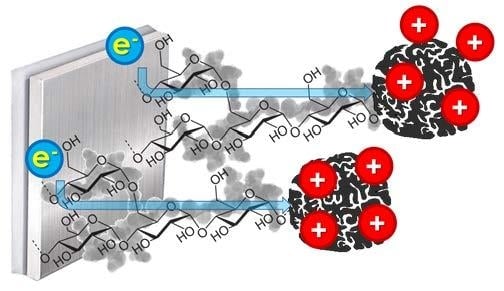
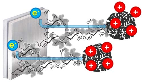
Electrochemical energy storage devices are composed of two electrodes separated by a porous membrane and soaked in electrolyte. In particular, for electric double-layer capacitors (EDLCs), the energy is stored in an electric double layer (EDL) formed at the electrode/electrolyte interface. Cations and anions in electrolytic solution are attracted to the oppositely charged electrode surfaces, which creates an electric potential difference (voltage). The higher the nominal voltage is (the difference in measured potential between the positive and negative electrode during cell operation), the higher the energy stored (1) and power density (2), according to Equations [1,2,3]:
where C is the capacitance (F), U is the nominal voltage (V), and ERS stands for the equivalent series, which represents all of the factors contributing to the overall value of resistance (Ω).
To reach high values of energy and power, it is necessary to reach a high nominal voltage and lower the resistance of the cell. Nonetheless, the capacitance part of the equation should not be omitted. The capacitance value increases the overall energy of the constructed device and strongly depends on the electrode materials used and final cell construction, according to the equation provided by Helmholtz [4] (3):
where ε is the electric permittivity (F m−1), S is the accessible surface area [m2], d is the thickness of the EDL (m), and the accessible surface area S is strictly related to the porosity of the electrode material. Equation (3) was developed later by Stern [5], who took into account that the diffusion coefficient at the electrolyte/electrode interphase caused by the agglomeration of differently charged species (ions) near the electrode surface. Calculation of capacitance value for supercapacitors according to the equation (3) has informative value. The theoretical values of electric permittivity found in the literature may differ from the practical values. The accessible surface for ions is not the same as the value of specific surface area (SSA) calculated from gas adsorption isotherms [6]. Moreover, the penetration of pores plays important role especially in the organic electrolytes due to the sieving effect [7]. Additional research and studies were done in this topic to analyze how the capacitance can be theoretically calculated and some mathematical models were proposed in the recent years by Nagy et al. [8] and Huang et al. [9], where the properties of the electrode/electrolyte interphase as well as the material porosity were taken into account.
However, for the practical reasons the formula (4) is used to calculate the capacitance [3]:
where Q is the charge accumulated (C), I is the current used during charging (A), t is the time of the charging process (s), and U is voltage (V).
Purely physical energy storage mechanisms are very fast and allow high values of power close to 10 kW kg−1 to be achieved [10,11]. To further improve such power values, research has synthesized and used different materials such as activated carbons, carbon cloths, carbon fibers, and other active materials due to their large surface area. However, electrode materials are composed not only of an active material but also a material for increasing the conductivity and a substance binding all components together. Recent reports have described the fabrication of electrode materials with desired properties, such as certain pore sizes and distributions thereof [12,13,14,15,16,17,18], or with the use of specially designed electrolytes [19,20,21,22,23,24,25]. Another approach is to increase the energy by so-called internal hybridization, where a cell is composed of two different electrodes, where one electrode exhibits battery-like behaviour, while the second electrode accumulates charge in an EDL [26,27,28,29,30,31]. To date, however, the impact of the binder has been omitted in the majority of these studies. There are only a few reports concerning the use of novel binders that can be categorized as “green” materials, which have a low impact on the natural environment. Some examples include cellulose [32], carboxymethylcellulose (CMC) [33,34], chitin/chitosan [35,36] and casein [37], just to mention a few. Nevertheless, there is a possibility of preparing so-called binder free electrodes; however, in most cases, for the preparation of electrodes, it is necessary to use sophisticated methods, conditions, or equipment [38,39].
In light of recent studies regarding starch-based binders, which present good cohesive properties, we have decided to pursue the interesting topic of “green” components for electrode preparation. In one study by Passerini [40], it was emphasized that for starch-based electrodes, the “EIS measurements suggest that the coating process needs to be optimized”, which gives space for improvement in this field. One reasonable approach would be to try and modify the contact surface between the current collector and electrode material [41,42,43]. Nevertheless, the etching of current collectors is difficult, and it is necessary to provide strict and harsh conditions to achieve suitable results. Varzi et al. [40] used an etched current collector however, we suggest a completely different approach: an electrode material and conductive glue based on starch, one casted on the other.
Starch is a naturally abundant polymer produced by many plants as a source of energy. It is worth noting that starch is the second most abundant biomaterial in nature. On the one hand, starch is environmentally friendly due to its renewable and biodegradable nature; on the other hand, it is inexpensive and widely available [44,45,46]. Therefore, starch has been used for years not only as a component of adhesives used for gluing paper but also as a binder in many industries [47]. Nevertheless, the binding capacity of starch in its native form is not strong enough [48]; thus, additives that increase its adhesive properties, such as polyacrylamides, polyvinyl alcohol, or polyvinyl acetate, are often used in the corresponding glue formulations [49,50,51,52]. The industrial use of native starch as a binder also limits the difficulty of obtaining an adhesive paste containing a sufficiently high amount of starch (on a dry basis) to create a continuous weld between the bound surfaces [53,54]. In addition, the gelling process, i.e., heating the starch slurry to 60–70 °C significantly increases the viscosity [55,56], making it difficult to pump the adhesive properly in automated production lines and spread it evenly over the surface to be bound. To reduce the viscosity, controlled depolymerization is performed, and appropriately selected auxiliary agents that modify the adhesive properties of the obtained glue are added [57,58].
The abovementioned reasons were the driving force for this work, which seeks to establish a preparation method for a conducting glue based on starch for energy storage devices, which could improve the charge propagation and power performance of electrochemical devices and compete with conductive glues available on the market.
2. Materials and Methods
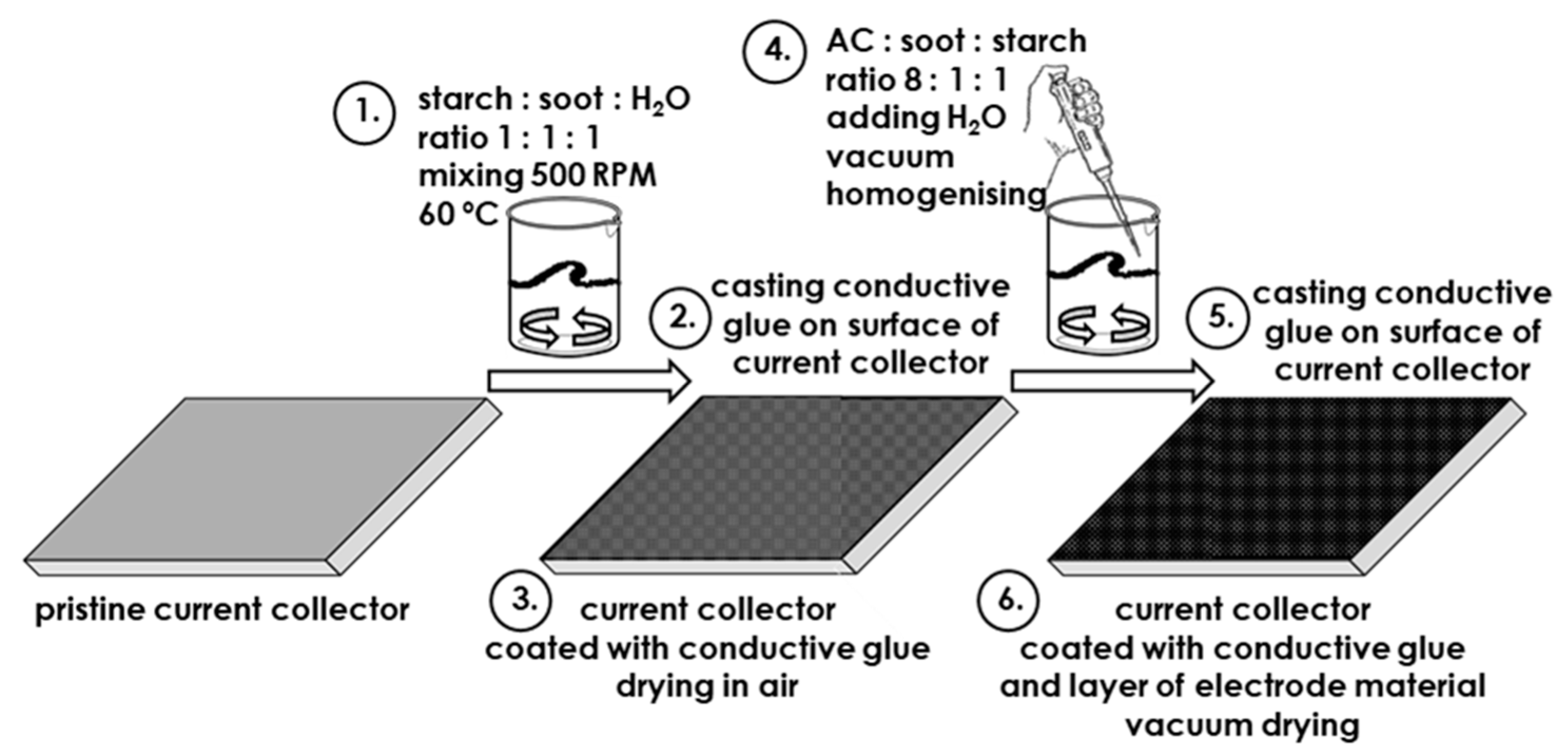
The conducting glue was prepared by mixing 1:1:1 (mass ratio) deionized water (solvent), starch and soot (Super C65, Imerys, France). The mixture was stirred with a mechanical stirrer at 500 RPM at an elevated temperature of 60 °C. Once gelation of the mixture was observed, the glue was spread on the surface of a current collector. To evenly distribute the conductive glue, stainless steel foil (S316L, thickness 10 μm, Materialis Elements, Wrocław, Poland) was placed on the perforated table of an automatic film applicator with a doctor blade attachment. The current collector sheet covered with conductive glue was transferred to a fume hood, and the excess solvent was evaporated by using a heating plate at 100 °C for 30 min. In the absence of the adhesive glue, extremely low charge propagation and high internal resistance were observed (Figure S1 in Supplementary Materials). The current collector sheet prepared for the CMC-based electrode material was covered with a commercially available conductive glue (ElectrodagTM PF-407C, Acheson, Düsseldorf, Germany). The casting and drying method was identical to that described above.
The electrode material was prepared according to the following composition: 80 wt. % activated carbon (Kuraray YP 80F, Tokyo, Japan, with characteristic Vmicro < 2 nm = 0.652 and SSA = 2093 m2 g−1), 10 wt. % carbon black (Super C65, Imerys, France) and 10 wt. % starch or carboxymethyl cellulose (referred to as CMC). Distilled water was added in ratios of 1 mL to 1 g of the dry electrode material mixture to decrease the viscosity until reaching a fluid-like consistency. The mixture was stirred at 20 °C using a vacuum homogenizer until a homogeneous suspension (slurry) was obtained. In the next step, the slurry was spread on the surface of the stainless steel foil covered, with conducting glue being used as the current collector. The gap between the blade and surface of the current collector was adjusted to 100 μm. The sheet of the current collector covered with the conductive glue and electrode material was transferred to a fume hood, and the excess solvent was evaporated using a heating plate at 100 °C for 1 h. Finally, to remove water from the pores of the activated carbon material, the electrode material sheet was dried under vacuum in a dryer (VACUCELL MM44, MMM Medcenter Einrichtungen GmbH, München, Germany) overnight at 100 °C. The dried material was subjected to calendaring to further improve cohesion and adhesion. The final thickness of the electrode material was ca. 70 μm. Electrodes in the form of discs with a diameter of 10 mm were cut out using an EL-CUT precision disc cutter (EL-CELL GmbH, Hamburg, Germany), and the measured mass loading for the electrodes was ca. 2 mg cm−1. The scheme of experimental procedure is presented in Figure 1.
The prepared electrodes were analyzed by scanning electron microscopy (SEM) (Quanta 250 FEG, Thermo Fisher Scientific, Waltham, MA, USA) at an accelerating voltage of 5 kV and a probe current of 100 pA.
A portion of the electrode material was used for the estimation of the specific surface area (SSA) and pore size distribution (PSD) according to the Brunauer–Emmett–Teller (BET) equation. SSA was estimated using the accelerated surface area and porosimetry system ASAP 2020 (Micromeritics Instrument Co., Norcross, GA, USA). Degassing of the investigated samples was performed for 24 h at 50 °C under vacuum. Gas adsorption was carried out at −196 °C with N2 as the adsorbate.
Swagelok cells were assembled in a glove box (UNILab 1200/780, M. Braun Inertgas-Systeme GmbH, Garching, Germany) with an oxygen and water level below 1 ppm to determine the capacitance value. Electrodes with the same diameter and similar masses were placed in a Swagelok cell. Both electrodes were separated by a porous glass fiber separator (GF/A, Whatman, Darmstadt, Germany, thickness 270 μm), and then electrolyte, one molar solution of tetraethylammonium tetrafluoroborate dissolved in acetonitrile (1 mol L−1 TEBF4 in ACN, 250 μL), was introduced into the system. A VMP3 potentiostat/galvanostat (Bio-Logic, France) was used for electrochemical testing. The techniques included galvanostatic cycling with potential limitation (GCPL) with a current density up to 50 A g−1 (the value was based on the total weight of the electrode material) in the voltage range from 0 to 2.5 V and electrochemical impedance spectroscopy (EIS) in the frequency range from 100 kHz to 10 mHz with an amplitude of 5 mV.
A VMP3 potentiostat/galvanostat (Bio-Logic Science Instruments, Seyssinet-Pariset, France) was used for electrochemical testing. GCPL was performed with a current density of C/20 and C/2 in the potential range from 10 mV to 1.5 V vs. Li0/Li+ (where C corresponds to the theoretical capacity of graphite, i.e., 372 mAh g−1).
3. Results and Discussion
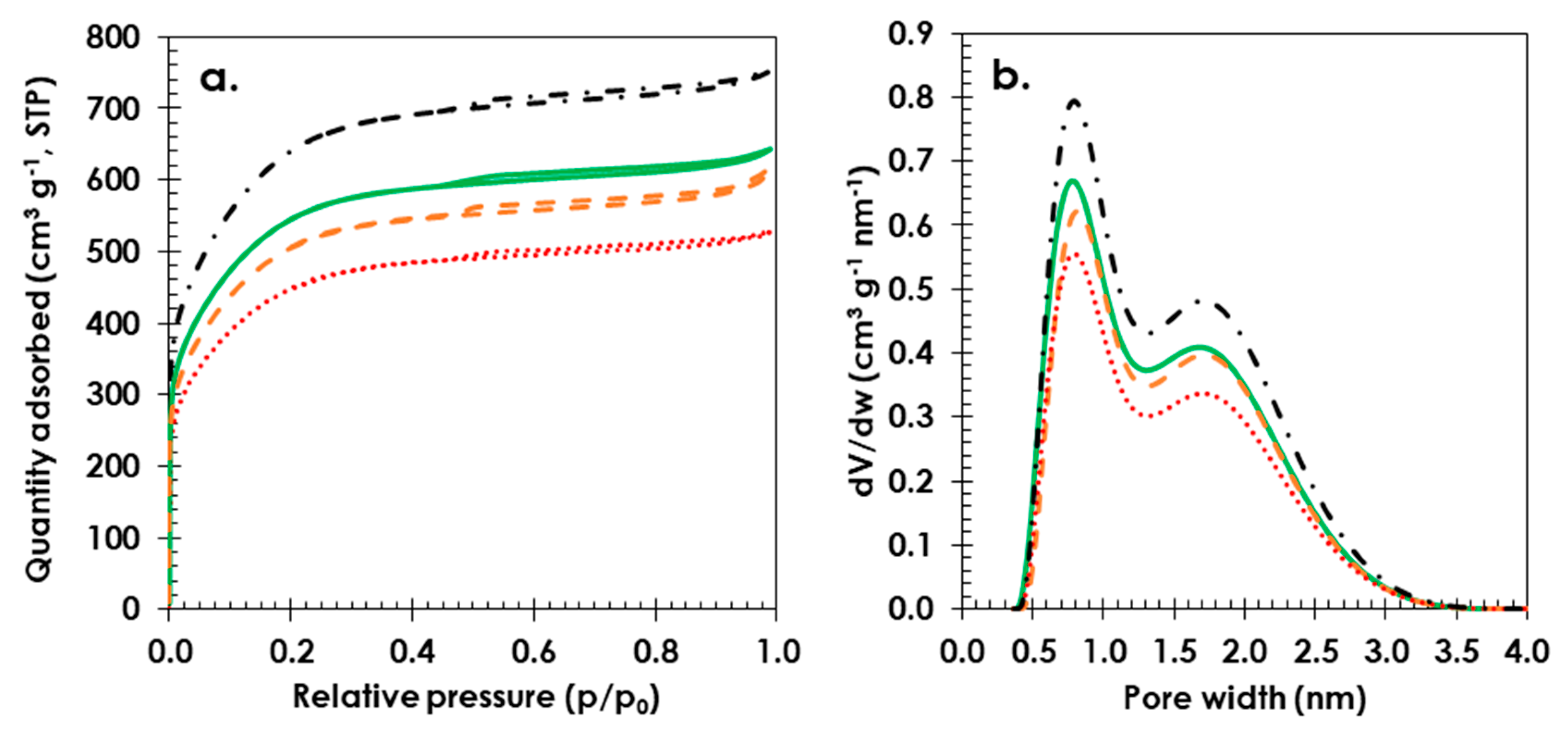
The gas adsorption analysis data presented in Figure 2 shows that the highest SSA was observed for the starch-based electrode material (1781 m2 g−1, solid green line) compared to that of polytetrafluoroethylene (PTFE) (1651 m2 g−1, dashed orange line), and the lowest value was detected for the CMC (1463 m2 g−1, dotted red line) bound electrode material. Based on the PSD data (Figure 2b), it seems that starch does not block micropores to the same extent as the PTFE or CMC binders. The starch-based electrode shows a cumulative micropore volume of Vmicro < 2 nm = 0.688, while that for the PTFE-bound electrode material is smaller, with a total micropore volume of Vmicro < 2 nm = 0.505; the value is even smaller for the electrode material with CMC (Vmicro < 2 nm = 0.453). The blockage of pores in AC materials by CMC has been reported by Richner et al., supporting the findings of this study [59]. Pristine AC powder (Kuraray YP80F) (dashed-dotted black line) has been added to Figure 2 as a reference.
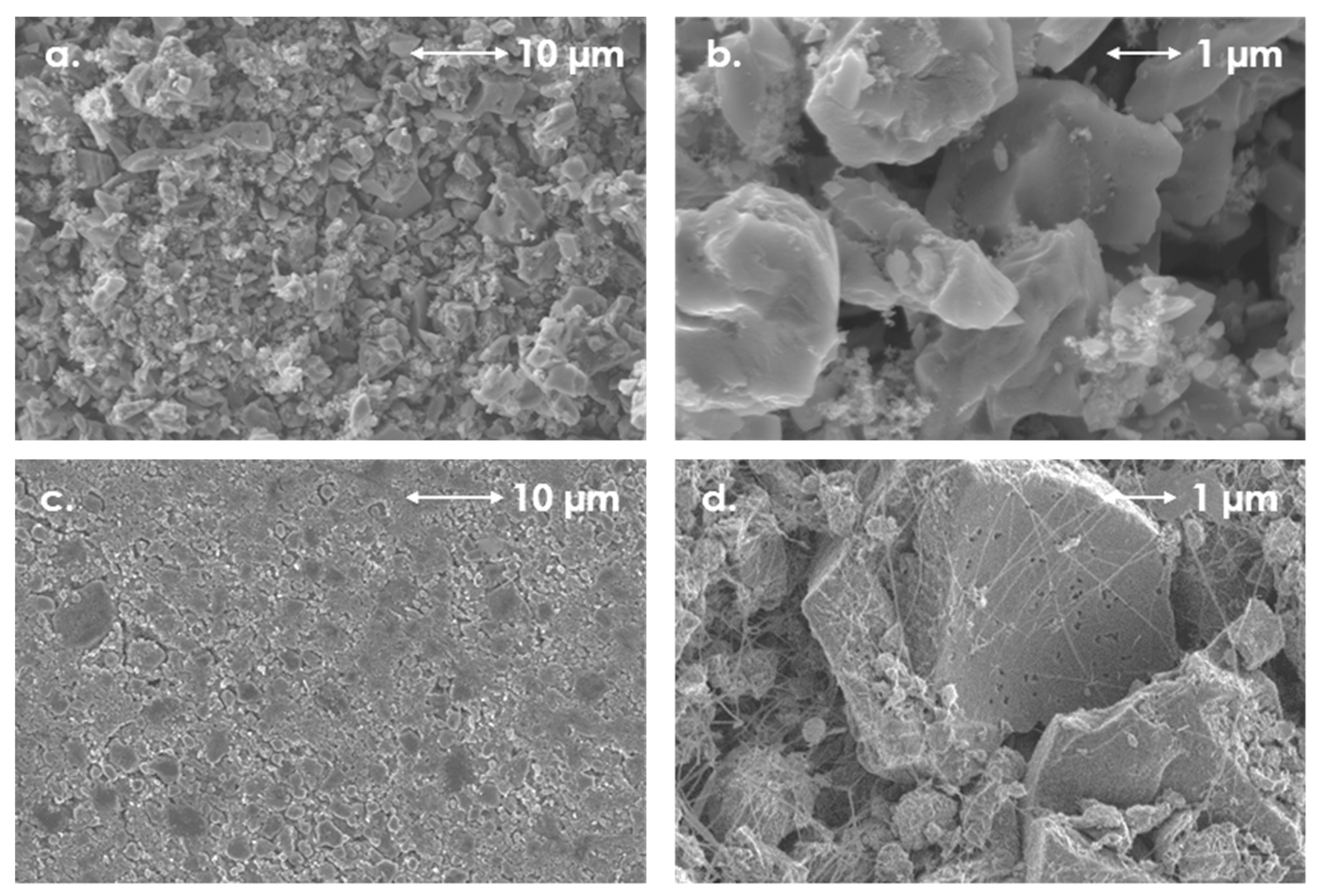
The SEM images demonstrate the morphologies of the electrode materials with starch (Figure 3a,b), PTFE (Figure 3c,d) and CMC (Figure 3e,f) as binders. In the case of starch and CMC, the morphology of electrode materials is very similar. For PTFE we observed a “spider-web” connections, where threads of PTFE link and bind material particles. In all of the cases, the obtained electrodes were homogenous and the soot particles were well dispersed among the activated carbon particles.
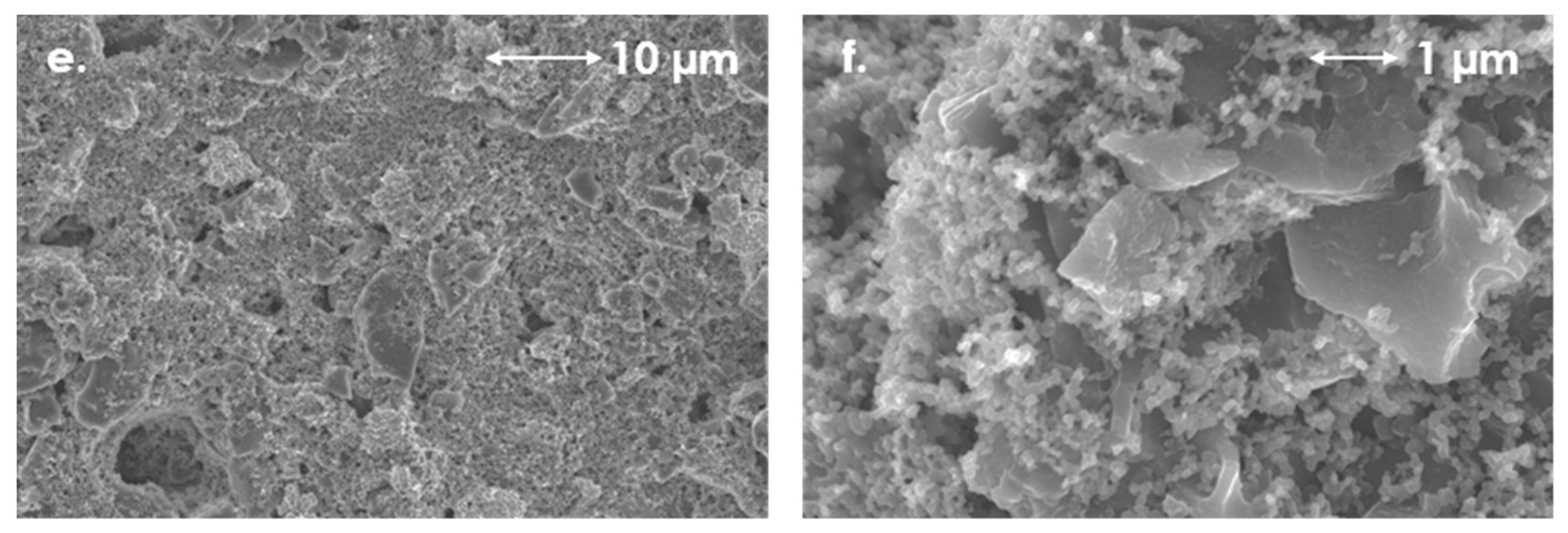
Figure 4 presents charging/discharging voltage profiles for EDLCs with starch-bound electrode materials coated on the surface of starch-based conductive glue. The triangular shape of these profiles and coulombic efficiency near 100% indicate no parasitic reactions in the presented system. For the lower current densities (0.5 A g−1), the lower efficiency at the initial cycles can be caused by the functional groups on surface of activated carbon. However, after several cycles it reaches the columbic efficiency of nearly 100% (Figure S2 in Supplementary Materials). For the higher current densities for example 50 A g−1 the observable ohmic drop (IR drop) is related with the internal resistance of the cell which increases when the value of passing current increases [60,61,62]. Moreover, in Figure S3 (in Supplementary Materials), we present additional data obtained for starch-bound electrodes operating in aqueous electrolyte (1 mol L−1 Na2SO4). However, this subject still needs additional work regarding the use of different types of starch and their modifications, which could prevent the dissolution of starch in water-based electrolytes for EDLCs during electrochemical cycling.
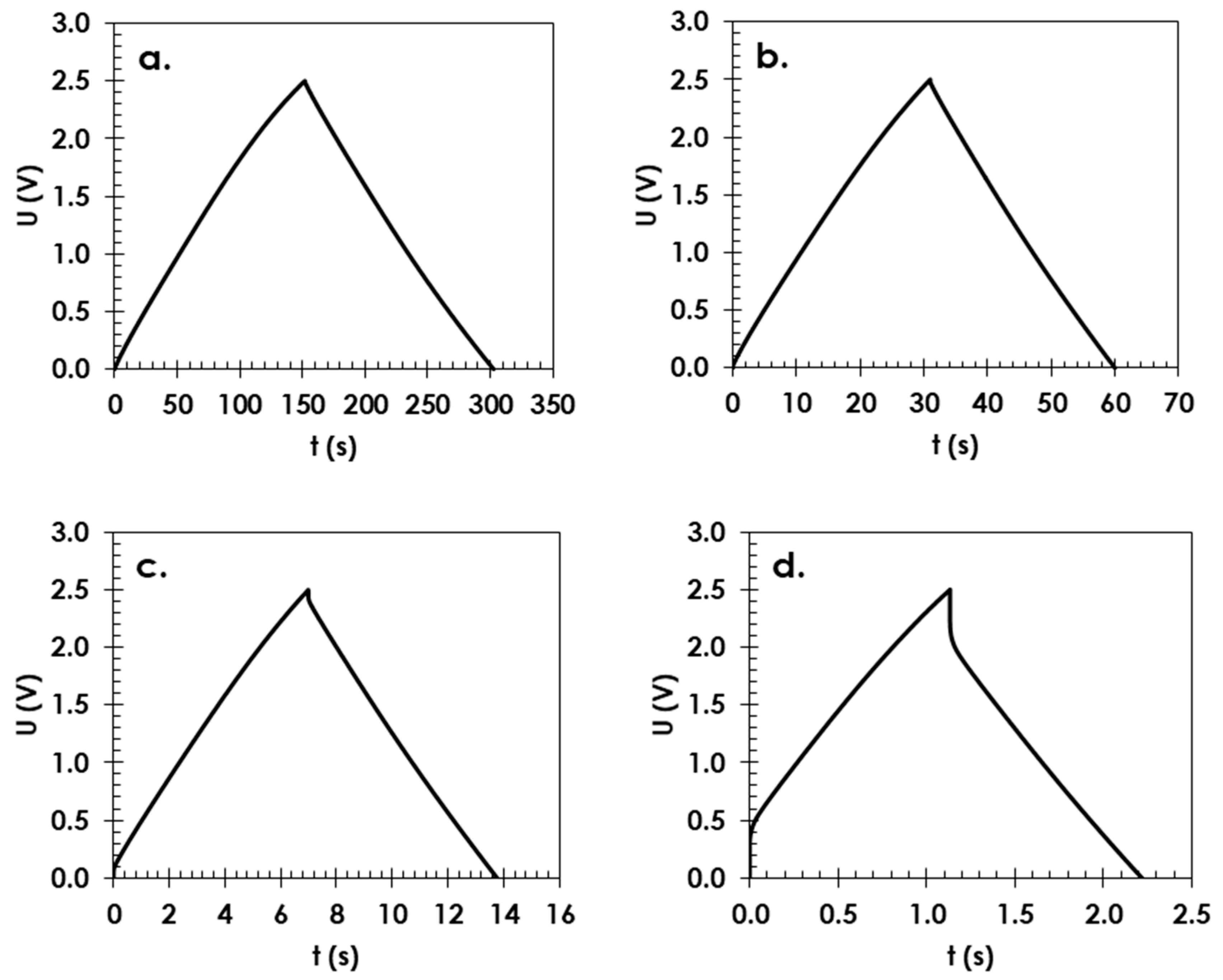
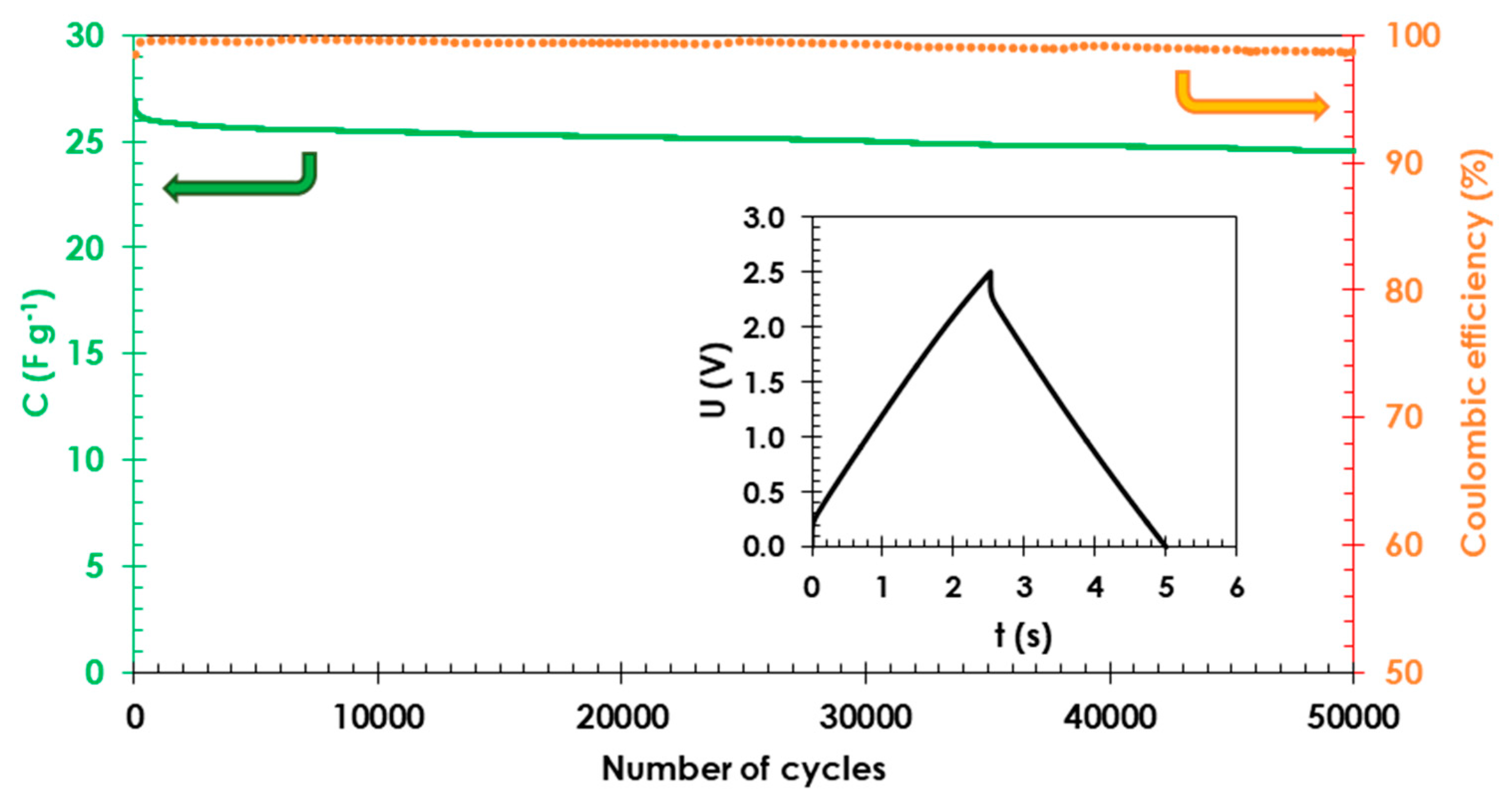
To establish the long-term stability of the electrode materials with starch binders, cells were continuously charged and discharged at a current of 25 A g−1 in a voltage range from 0.0 to 2.5 V. The table capacitance value (green solid line) during 50,000 cycles (capacitance retention of 95% compared to the initial value before cycling) and high coulombic efficiency of 98%, as shown in Figure 5, suggest that starch can be used as a binder for electrode materials and as a conductive glue in EDLCs with long lifespans.
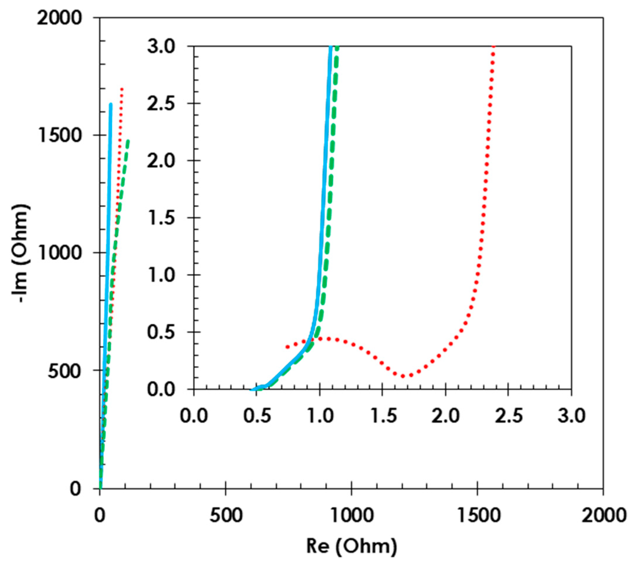
Nyquist plots (Figure 6) show that the EDLC constructed with conductive glue and electrodes incorporating the starch binder has an equivalent distributed resistance (EDR) = 0.9, which is lower than for CMC-bound electrodes, where the EDR value is 2.2 Ω.
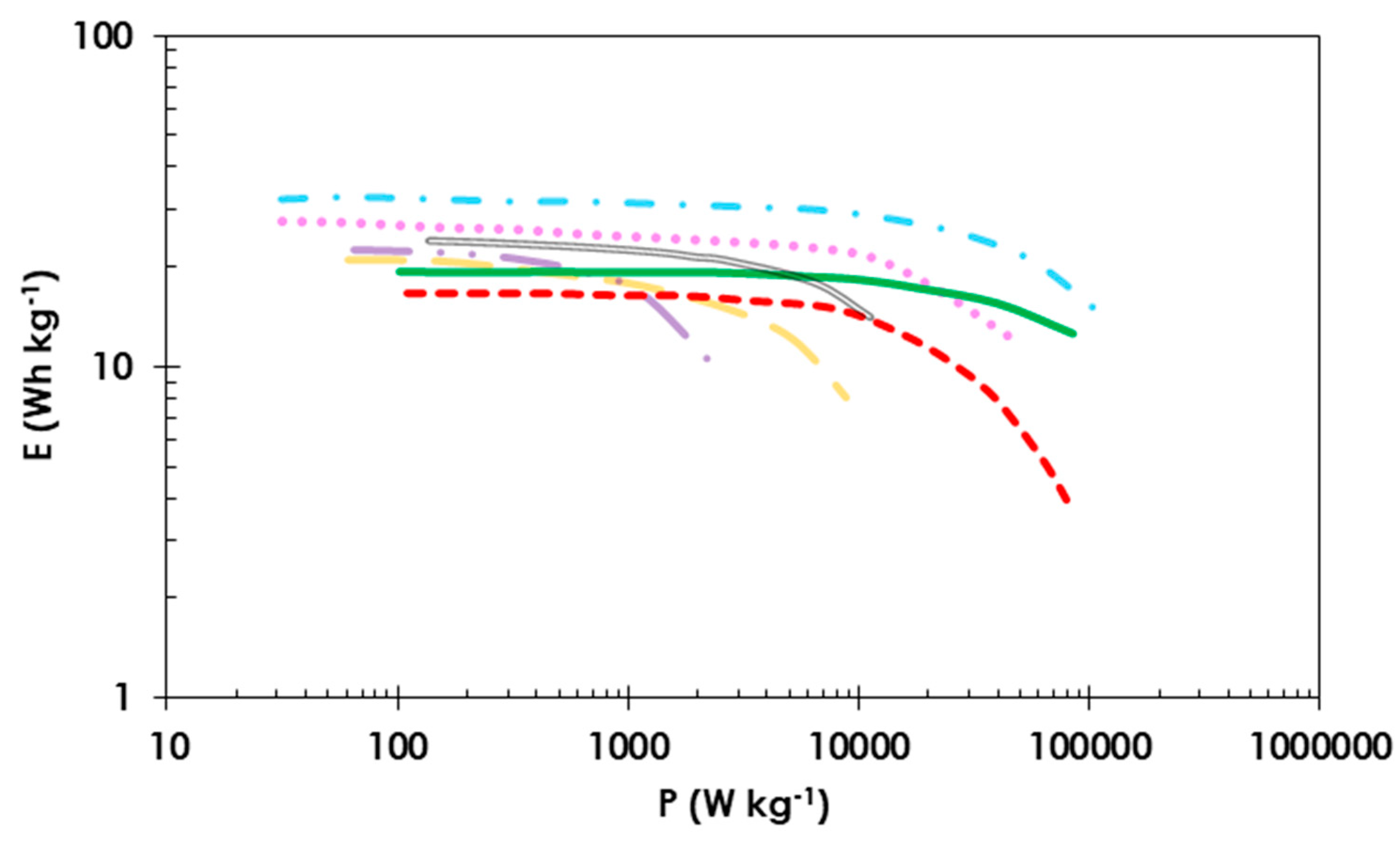
The two EDLC systems operating at 2.5 V with starch or CMC as the binder are compared in a Ragone plot (Figure 7). The starch-based EDLC has a higher specific energy of 20 Wh kg−1 than the EDLC with CMC-bound electrodes (17 Wh kg−1). At high power values (>10 kW kg−1), the energy density of the cell with commercially available conductive glue and CMC binder starts to decrease, most likely because of the higher internal resistance; thus, the specific energy is 4 Wh kg−1 at a specific power of 100 kW kg−1. In the case of the EDLC utilizing starch-bound electrodes and conductive glue, it is possible to reach a high specific energy of 12 Wh kg−1 at a specific power of 100 kW kg−1. Obtained results were compared with other data found in the literature about symmetric electrochemical capacitors with carbon electrodes. All of the cells operate in organic electrolyte with TEABF4 where salt concentration is 1 mol L−1 [63,64,65,66]. It shows that the use starch conductive glue allows us to reach high values of power without a noticeable fade of energy, especially when reaching the value of specific power 10 kW kg−1.
4. Conclusions
Starch can be considered as a “green” binder material for the fabrication of conducting glue and electrodes for energy storage devices. The manufacturing process does not involve any toxic or harmful solvents. The electrochemical characteristics of electrode materials incorporating starch as a binder and a layer of starch-based conductive glue provide better results than the commonly used “green” binder, CMC. The use of relatively high current loads, such as 50 A g−1, is possible for cells where the electrode material is fixed to the current collector with a starch-based conducting glue, and such cells exhibit better charge propagation, excellent capacitance retention and relatively small resistance. Moreover, preliminary studies have shown that starch binder can be used in aqueous electrolytes, which will be investigated further in the future.
Supplementary Materials
The following are available online at https://0-www-mdpi-com.brum.beds.ac.uk/2073-4360/11/10/1648/s1, Figure S1: Comparative Nyquist plots for EDLC with starch as a binder in conductive glue for improved adhesion of electrode material to current collector (green solid line) and without adhesive conductive layer (red dotted line). Composition of electrodes 80 wt. % activated carbon (YP 80F) 10 wt. % carbon black (Super C65) and 10 wt. % starch. Figure S2: Cyclability of EDLC cells with starch binder in the voltage range from 0.0 V to 2.5 V at a current density of 0.5 A g−1 and 1 mol L−1 TEABF4 in ACN used as the electrolyte. Capacitance values and columbic efficiency are represented as a solid green line and dotted orange line, respectively. Composition of electrodes 80 wt. % activated carbon (YP 80F) 10 wt. % carbon black (Super C65) and 10 wt. % starch. Figure S3: Electrode potential profiles and cell voltage of EDLC operating with aqueous electrolyte (1 mol L−1 Na2SO4) at current density 1.0 A g−1. Composition of electrodes 80 wt. % activated carbon (YP 80F) 10 wt. % carbon black (Super C65) and 10 wt. % starch.
Author Contributions
Conceptualization, P.J.; Investigation, P.J. and P.Ł.K.; Methodology, P.J.; Writing—original draft, P.J. and P.Ł.K.
Funding
The European Commission (EC), in the form of the European Research Council (ERC), is acknowledged for funding provided within the ERC-StG-2017 project (grant agreement No. 759603) under the European Union’s Horizon 2020 research and innovation programme (PI: Krzysztof Fic) and Polish Ministry of Science and Higher Education 03/31/SBAD/0383.
Acknowledgments
Authors would like to express gratitude towards Krzysztof Fic for the scientific and merit discussion, as well as François Béguin and Elżbieta Frąckowiak for their input in the scientific development of the Power Sources Group.
Conflicts of Interest
On behalf of all authors, the corresponding author states that there is no conflict of interest.
References
- Kötz, R.; Carlen, M. Principles and applications of electrochemical capacitors. Electrochim. Acta 2000, 45, 2483–2498. [Google Scholar] [CrossRef]
- Conway, B.E. Electrochemical Supercapacitors; Springer: Boston, MA, USA, 1999; ISBN 978-1-4757-3060-9. [Google Scholar]
- Lu, M. Supercapacitors: Materials, Systems, and Applications; Béguin, F., Frąckowiak, E., Eds.; Wiley-VCH: Weinheim, Germany, 2013; ISBN 9783527328833. [Google Scholar]
- Helmholtz, H. Ueber einige Gesetze der Vertheilung elektrischer Ströme in körperlichen Leitern mit Anwendung auf die thierisch-elektrischen Versuche. Annalen der Physik 1853, 165, 211–233. [Google Scholar] [CrossRef]
- Stern, O. Zur Theorie Der Elektrolytischen Doppelschicht. Zeitschrift für Elektrochemie und Angewandte Physikalische Chemie 1924, 30, 508–516. [Google Scholar] [CrossRef]
- Koresh, J. Double Layer Capacitance and Charging Rate of Ultramicroporous Carbon Electrodes. J. Electrochem. Soc. 1977, 124, 1379. [Google Scholar] [CrossRef]
- Salitra, G.; Soffer, A.; Eliad, L.; Cohen, Y.; Aurbach, D. Carbon Electrodes for Double-Layer Capacitors I. Relations Between Ion and Pore Dimensions. J. Electrochem. Soc. 2000, 147, 2486. [Google Scholar] [CrossRef]
- Nagy, T.; Henderson, D.; Boda, D. Simulation of an Electrical Double Layer Model with a Low Dielectric Layer between the Electrode and the Electrolyte. J. Phys. Chem. B 2011, 115, 11409–11419. [Google Scholar] [CrossRef]
- Huang, J.; Sumpter, B.G.; Meunier, V. Theoretical Model for Nanoporous Carbon Supercapacitors. Angew. Chem. Int. Ed. 2008, 47, 520–524. [Google Scholar] [CrossRef] [PubMed]
- Gogotsi, Y.; Simon, P. True Performance Metrics in Electrochemical Energy Storage. Science 2011, 334, 917–918. [Google Scholar] [CrossRef] [PubMed] [Green Version]
- Brousse, T.; Bélanger, D.; Long, J.W. To Be or Not To Be Pseudocapacitive? J. Electrochem. Soc. 2015, 162, A5185–A5189. [Google Scholar] [CrossRef] [Green Version]
- Hulicova-Jurcakova, D.; Seredych, M.; Lu, G.Q.; Bandosz, T.J. Combined Effect of Nitrogen- and Oxygen-Containing Functional Groups of Microporous Activated Carbon on its Electrochemical Performance in Supercapacitors. Adv. Funct. Mater. 2009, 19, 438–447. [Google Scholar] [CrossRef]
- Raymundo-Piñero, E.; Kierzek, K.; Machnikowski, J.; Béguin, F. Relationship between the nanoporous texture of activated carbons and their capacitance properties in different electrolytes. Carbon 2006, 44, 2498–2507. [Google Scholar] [CrossRef]
- Frackowiak, E.; Lota, G.; Machnikowski, J.; Vix-Guterl, C.; Béguin, F. Optimisation of supercapacitors using carbons with controlled nanotexture and nitrogen content. Electrochim. Acta 2006, 51, 2209–2214. [Google Scholar] [CrossRef]
- Stoeckli, F.; Centeno, T.A. On the determination of surface areas in activated carbons. Carbon 2005, 43, 1184–1190. [Google Scholar] [CrossRef] [Green Version]
- Hulicova, D.; Kodama, M.; Hatori, H. Electrochemical Performance of Nitrogen-Enriched Carbons in Aqueous and Non-Aqueous Supercapacitors. Chem. Mater. 2006, 18, 2318–2326. [Google Scholar] [CrossRef]
- Paraknowitsch, J.P.; Thomas, A. Doping carbons beyond nitrogen: An overview of advanced heteroatom doped carbons with boron, sulphur and phosphorus for energy applications. Energy Environ. Sci. 2013, 6, 2839. [Google Scholar] [CrossRef]
- Béguin, F.; Presser, V.; Balducci, A.; Frackowiak, E. Carbons and Electrolytes for Advanced Supercapacitors. Adv. Mater. 2014, 26, 2219–2251. [Google Scholar] [CrossRef] [PubMed]
- Chmiola, J. Anomalous Increase in Carbon Capacitance at Pore Sizes Less Than 1 Nanometer. Science 2006, 313, 1760–1763. [Google Scholar] [CrossRef] [PubMed] [Green Version]
- Gao, Q.; Demarconnay, L.; Raymundo-Piñero, E.; Béguin, F. Exploring the large voltage range of carbon/carbon supercapacitors in aqueous lithium sulfate electrolyte. Energy Environ. Sci. 2012, 5, 9611. [Google Scholar] [CrossRef]
- Fic, K.; Lota, G.; Meller, M.; Frackowiak, E. Novel insight into neutral medium as electrolyte for high-voltage supercapacitors. Energy Environ. Sci. 2012, 5, 5842–5850. [Google Scholar] [CrossRef]
- Abbas, Q.; Babuchowska, P.; Frąckowiak, E.; Béguin, F. Sustainable AC/AC hybrid electrochemical capacitors in aqueous electrolyte approaching the performance of organic systems. J. Power Sources 2016, 326, 652–659. [Google Scholar] [CrossRef]
- Moreno-Fernández, G.; Schütter, C.; Rojo, J.M.; Passerini, S.; Balducci, A.; Centeno, T.A. On the interaction of carbon electrodes and non conventional electrolytes in high-voltage electrochemical capacitors. J. Solid State Electrochem. 2018, 22, 717–725. [Google Scholar] [CrossRef]
- Aradilla, D.; Gao, F.; Lewes-Malandrakis, G.; Müller-Sebert, W.; Gentile, P.; Boniface, M.; Aldakov, D.; Iliev, B.; Schubert, T.J.S.; Nebel, C.E.; et al. Designing 3D Multihierarchical Heteronanostructures for High-Performance On-Chip Hybrid Supercapacitors: Poly(3,4-(ethylenedioxy)thiophene)-Coated Diamond/Silicon Nanowire Electrodes in an Aprotic Ionic Liquid. ACS Appl. Mater. Interfaces 2016, 8, 18069–18077. [Google Scholar] [CrossRef] [PubMed]
- Dai, Z.; Peng, C.; Chae, J.H.; Ng, K.C.; Chen, G.Z. Cell voltage versus electrode potential range in aqueous supercapacitors. Sci. Rep. 2015, 5, 9854. [Google Scholar] [CrossRef] [PubMed] [Green Version]
- Jeżowski, P.; Fic, K.; Crosnier, O.; Brousse, T.; Béguin, F. Use of sacrificial lithium nickel oxide for loading graphitic anode in Li-ion capacitors. Electrochim. Acta 2016, 206, 440–445. [Google Scholar] [CrossRef]
- Du Pasquier, A.; Plitz, I.; Menocal, S.; Amatucci, G. A comparative study of Li-ion battery, supercapacitor and nonaqueous asymmetric hybrid devices for automotive applications. J. Power Sources 2003, 115, 171–178. [Google Scholar] [CrossRef]
- Jeżowski, P.; Fic, K.; Crosnier, O.; Brousse, T.; Béguin, F. Lithium rhenium(VII) oxide as a novel material for graphite pre-lithiation in high performance lithium-ion capacitors. J. Mater. Chem. A 2016, 4, 12609–12615. [Google Scholar] [CrossRef]
- Naoi, K.; Ishimoto, S.; Isobe, Y.; Aoyagi, S. High-rate nano-crystalline Li4Ti5O12 attached on carbon nano-fibers for hybrid supercapacitors. J. Power Sources 2010, 195, 6250–6254. [Google Scholar] [CrossRef]
- Jeżowski, P.; Crosnier, O.; Deunf, E.; Poizot, P.; Béguin, F.; Brousse, T. Safe and recyclable lithium-ion capacitors using sacrificial organic lithium salt. Nat. Mater. 2018, 17, 167–173. [Google Scholar] [CrossRef]
- Aida, T.; Murayama, I.; Yamada, K.; Morita, M. Improvement in Cycle Performance of a High-Voltage Hybrid Electrochemical Capacitor. Electrochem. Solid-State Lett. 2007, 10, A93. [Google Scholar] [CrossRef]
- Böckenfeld, N.; Jeong, S.S.; Winter, M.; Passerini, S.; Balducci, A. Natural, cheap and environmentally friendly binder for supercapacitors. J. Power Sources 2013, 221, 14–20. [Google Scholar] [CrossRef]
- Krause, A.; Balducci, A. High voltage electrochemical double layer capacitor containing mixtures of ionic liquids and organic carbonate as electrolytes. Electrochem. Commun. 2011, 13, 814–817. [Google Scholar] [CrossRef]
- Krause, A.; Kossyrev, P.; Oljaca, M.; Passerini, S.; Winter, M.; Balducci, A. Electrochemical double layer capacitor and lithium-ion capacitor based on carbon black. J. Power Sources 2011, 196, 8836–8842. [Google Scholar] [CrossRef]
- Kolodziej, A.; Fic, K.; Frackowiak, E. Towards sustainable power sources: Chitin-bound carbon electrodes for electrochemical capacitors. J. Mater. Chem. A 2015, 3, 22923–22930. [Google Scholar] [CrossRef]
- Choudhury, N.A.; Northrop, P.W.C.; Crothers, A.C.; Jain, S.; Subramanian, V.R. Chitosan hydrogel-based electrode binder and electrolyte membrane for EDLCs: Experimental studies and model validation. J. Appl. Electrochem. 2012, 42, 935–943. [Google Scholar] [CrossRef]
- Varzi, A.; Raccichini, R.; Marinaro, M.; Wohlfahrt-Mehrens, M.; Passerini, S. Probing the characteristics of casein as green binder for non-aqueous electrochemical double layer capacitors’ electrodes. J. Power Sources 2016, 326, 672–679. [Google Scholar] [CrossRef]
- Gao, H.; Lian, K. Proton-conducting polymer electrolytes and their applications in solid supercapacitors: A review. RSC Adv. 2014, 4, 33091–33113. [Google Scholar] [CrossRef]
- Zhang, Y.; Sun, X.; Pan, L.; Li, H.; Sun, Z.; Sun, C.; Tay, B.K. Carbon nanotube–ZnO nanocomposite electrodes for supercapacitors. Solid State Ion. 2009, 180, 1525–1528. [Google Scholar] [CrossRef]
- Varzi, A.; Passerini, S. Enabling high areal capacitance in electrochemical double layer capacitors by means of the environmentally friendly starch binder. J. Power Sources 2015, 300, 216–222. [Google Scholar] [CrossRef]
- Portet, C.; Taberna, P.; Simon, P.; Laberty-Robert, C. Modification of Al current collector surface by sol–gel deposit for carbon–carbon supercapacitor applications. Electrochim. Acta 2004, 49, 905–912. [Google Scholar] [CrossRef]
- Taberna, P.L.; Portet, C.; Simon, P. Electrode surface treatment and electrochemical impedance spectroscopy study on carbon/carbon supercapacitors. Appl. Phys. A 2006, 82, 639–646. [Google Scholar] [CrossRef]
- Jeżowski, P.; Nowicki, M.; Grzeszkowiak, M.; Czajka, R.; Béguin, F. Chemical etching of stainless steel 301 for improving performance of electrochemical capacitors in aqueous electrolyte. J. Power Sources 2015, 279, 555–562. [Google Scholar] [CrossRef]
- Gross, R.A.; Kalra, B. Biodegradable Polymers for the Environment. Science 2002, 297, 803–807. [Google Scholar] [CrossRef] [PubMed] [Green Version]
- Lu, D.R.; Xiao, C.M.; Xu, S.J. Starch-based completely biodegradable polymer materials. Express Polym. Lett. 2009, 3, 366–375. [Google Scholar] [CrossRef]
- Makowska, A.; Szwengiel, A.; Kubiak, P.; Tomaszewska-Gras, J. Characteristics and structure of starch isolated from triticale. Starch Stärke 2014, 66, 895–902. [Google Scholar] [CrossRef]
- Kennedy, H.M. Starch- and Dextrin-Based Adhesives. In Adhesives from Renewable Resources; ACS Publication: Washington, DC, USA, 1989; pp. 326–336. [Google Scholar]
- Imam, S.H.; Gordon, S.H.; Mao, L.; Chen, L. Environmentally friendly wood adhesive from a renewable plant polymer: Characteristics and optimization. Polym. Degrad. Stab. 2001, 73, 529–533. [Google Scholar] [CrossRef]
- Wang, Z.; Li, Z.; Gu, Z.; Hong, Y.; Cheng, L. Preparation, characterization and properties of starch-based wood adhesive. Carbohydr. Polym. 2012, 88, 699–706. [Google Scholar] [CrossRef]
- Zhang, Y.; Ding, L.; Gu, J.; Tan, H.; Zhu, L. Preparation and properties of a starch-based wood adhesive with high bonding strength and water resistance. Carbohydr. Polym. 2015, 115, 32–37. [Google Scholar] [CrossRef] [PubMed]
- Le Thanh-Blicharz, J.; Lubiewski, Z.; Voelkel, E.; Lewandowicz, G. Evaluation of rheological properties of commercial native starches. Zywnosc Nauka Technologia Jakosc/Food Sci. Technol. Qual. 2011, 18, 53–65. [Google Scholar] [CrossRef]
- Makowska, A.; Kubiak, P.; Bialas, W.; Lewandowicz, G. Effect of urea, sodium nitrate and ethylene glycol addition on the rheological properties of corn starch pastes. Polimery 2015, 60, 343–350. [Google Scholar] [CrossRef]
- Kilbride, P.; Rull, M.V.; Townsend, A.; Wilson, H.; Morris, J. Shear-thickening fluids in biologically relevant agents. Biorheology 2019, 1–12. [Google Scholar] [CrossRef]
- Ma, Y.; Wu, S.; Tong, J.; Zhang, X.; Peng, J.; Liu, X. Rheological Properties of Corn Starch Dispersions in Pregelatinized Starch Solution. In Proceedings of the 2018 IEEE International Conference on Manipulation, Manufacturing and Measurement on the Nanoscale (3M-NANO), Hangzhou, China, 13–17 August 2018; pp. 146–150. [Google Scholar]
- Ai, Y.; Jane, J. Gelatinization and rheological properties of starch. Starch Stärke 2015, 67, 213–224. [Google Scholar] [CrossRef]
- Baranowska, H.M.; Sikora, M.; Krystyjan, M.; Tomasik, P. Analysis of the formation of starch—Hydrocolloid binary gels and their structure based on the relaxation times of the water molecules. Polimery 2011, 56, 478–483. [Google Scholar] [CrossRef]
- Thirumdas, R.; Kadam, D.; Annapure, U.S. Cold Plasma: An Alternative Technology for the Starch Modification. Food Biophys. 2017, 12, 129–139. [Google Scholar] [CrossRef]
- Wang, Y.-J.; Truong, V.-D.; Wang, L. Structures and rheological properties of corn starch as affected by acid hydrolysis. Carbohydr. Polym. 2003, 52, 327–333. [Google Scholar] [CrossRef]
- Richner, R.; Müller, S.; Bärtschi, M.; Kötz, R.; Wokaun, A. Physically and Chemically Bonded Carbonaceous Material for Double-Layer Capacitor Applications. J. New Mater. Electrochem. Syst. 2002, 5, 297–304. [Google Scholar]
- Maletin, Y.; Strelko, V.; Stryzhakova, N.; Zelinsky, S.; Rozhenko, A.B.; Gromadsky, D.; Volkov, V.; Tychina, S.; Gozhenko, O.; Drobny, D. Carbon Based Electrochemical Double Layer Capacitors of Low Internal Resistance. Energy Environ. Res. 2013, 3. [Google Scholar] [CrossRef]
- Maletin, Y.; Stryzhakova, N.; Zelinsky, S.; Chernukhin, S.; Tretyakov, D.; Tychina, S.; Drobny, D. Electrochemical Double Layer Capacitors and Hybrid Devices for Green Energy Applications. Green 2014, 4. [Google Scholar] [CrossRef]
- Yurii Maletin, N.S.; Sergii Zelinskyi, S.C.; Dmytro Tretyakov, H.M.; Natalia, D.; Dmytro, D. New Approach to Ultracapacitor Technology: What it Can Offer to Electrified Vehicles. J. Energy Power Eng. 2015, 9. [Google Scholar] [CrossRef] [Green Version]
- Sevilla, M.; Fuertes, A.B. Direct Synthesis of Highly Porous Interconnected Carbon Nanosheets and Their Application as High-Performance Supercapacitors. ACS Nano 2014, 8, 5069–5078. [Google Scholar] [CrossRef] [Green Version]
- Brandt, A.; Balducci, A. Theoretical and practical energy limitations of organic and ionic liquid-based electrolytes for high voltage electrochemical double layer capacitors. J. Power Sources 2014, 250, 343–351. [Google Scholar] [CrossRef]
- Krüner, B.; Odenwald, C.; Quade, A.; Kickelbick, G.; Presser, V. Influence of Nitrogen-Doping for Carbide-Derived Carbons on the Supercapacitor Performance in an Organic Electrolyte and an Ionic Liquid. Batter. Supercaps 2018, 1, 135–148. [Google Scholar] [CrossRef]
- Krüner, B.; Lee, J.; Jäckel, N.; Tolosa, A.; Presser, V. Sub-micrometer Novolac-Derived Carbon Beads for High Performance Supercapacitors and Redox Electrolyte Energy Storage. ACS Appl. Mater. Interfaces 2016, 8, 9104–9115. [Google Scholar] [CrossRef] [PubMed]
Figure 1.
Scheme of the experimental procedure.

Figure 2.
Gas adsorption data: (a) adsorption/desorption Brunauer-Emmett-Teller (BET) isotherms and (b) pore size distribution (PSD) curves for pristine activated carbon (Kuraray YP 80F) (dashed-dotted black line) and electrodes with different binders: starch (solid green line), PTFE (dashed orange line) and CMC (dotted red line). Composition of electrode material 80 wt. % activated carbon (YP 80F) 10 wt. % carbon black (Super C65) and 10 wt. % binder.

Figure 3.
SEM images of electrodes with different binders: starch (a,b), PTFE (c,d) and CMC (e,f), at different magnifications (scale added to the images). Composition of electrode material 80 wt. % activated carbon (YP 80F) 10 wt. % carbon black (Super C65) and 10 wt. % binder.
Figure 3.
SEM images of electrodes with different binders: starch (a,b), PTFE (c,d) and CMC (e,f), at different magnifications (scale added to the images). Composition of electrode material 80 wt. % activated carbon (YP 80F) 10 wt. % carbon black (Super C65) and 10 wt. % binder.


Figure 4.
Charge/discharge profiles in the voltage range 0.0 to 2.5 V for EDLCs operating at different current densities: (a) 0.5 A g−1, (b) 2.5 A g−1, (c) 10 A g−1 and (d) 50 A g−1, with 1 mol L−1 TEABF4 in ACN as the electrolyte. Composition of electrode material 80 wt. % activated carbon (YP 80F) 10 wt. % carbon black (Super C65) and 10 wt. % starch.

Figure 5.
Cyclability of EDLC cells with starch binder in the voltage range from 0.0 to 2.5 V at a current density of 25 A g−1 and 1 mol L−1 TEABF4 in ACN used as the electrolyte. Capacitance values and columbic efficiency are represented as a solid green line and dotted orange line, respectively. Composition of electrode material 80 wt. % activated carbon (YP 80F) 10 wt. % carbon black (Super C65) and 10 wt. % starch.

Figure 6.
Comparative Nyquist plots for EDLCs with starch as an electrode material binder before (solid blue line) and after cycling life studies (dashed green line) and with CMC as a binder (dotted red line). Composition of electrode material 80 wt. % activated carbon (YP 80F) 10 wt. % carbon black (Super C65) and 10 wt. % binder. 1 mol L−1 TEABF4 in ACN was used as the electrolyte.

Figure 7.
Comparative Ragone plot for EDLC cells in which starch (solid green line) or CMC (dashed red line) was used as a binder. Cells were tested up to 2.5 V in 1 mol L−1 TEABF4 in ACN. Composition of electrode material 80 wt. % activated carbon (YP 80F) 10 wt. % carbon black (Super C65) and 10 wt. % binder. The reference curves were made according to the data from: [63] (dot-dashed light blue line), [64] (double grey line), [65] (dotted light pink line), [66] (long dashed light orange line and dot-dot-dashed light purple line).

© 2019 by the authors. Licensee MDPI, Basel, Switzerland. This article is an open access article distributed under the terms and conditions of the Creative Commons Attribution (CC BY) license (http://creativecommons.org/licenses/by/4.0/).
Share and Cite
MDPI and ACS Style
Jeżowski, P.; Kowalczewski, P.Ł. Starch as a Green Binder for the Formulation of Conducting Glue in Supercapacitors. Polymers 2019, 11, 1648. https://0-doi-org.brum.beds.ac.uk/10.3390/polym11101648
AMA Style
Jeżowski P, Kowalczewski PŁ. Starch as a Green Binder for the Formulation of Conducting Glue in Supercapacitors. Polymers. 2019; 11(10):1648. https://0-doi-org.brum.beds.ac.uk/10.3390/polym11101648
Chicago/Turabian StyleJeżowski, Paweł, and Przemysław Łukasz Kowalczewski. 2019. "Starch as a Green Binder for the Formulation of Conducting Glue in Supercapacitors" Polymers 11, no. 10: 1648. https://0-doi-org.brum.beds.ac.uk/10.3390/polym11101648
Note that from the first issue of 2016, this journal uses article numbers instead of page numbers. See further details here.