Effect of Alumina Nanowires on the Thermal Conductivity and Electrical Performance of Epoxy Composites

Abstract
:
1. Introduction
2. Materials and Methods
2.1. Materials
2.2. Preparation of Al2O3-NWs and Epoxy Composites
2.3. Performance Analysis
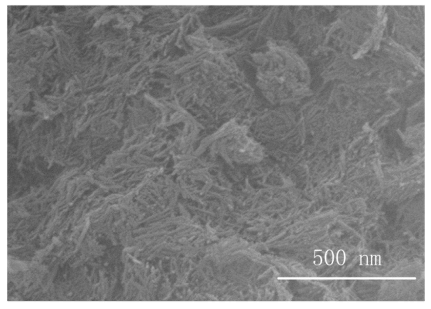
2.3.1. SEM Imaging
2.3.2. Thermal Conductivity
2.3.3. Thermal Stability
2.3.4. Volume Resistivity
2.3.5. Dielectric Performance
2.3.6. Breakdown Strength
3. Results and Discussion
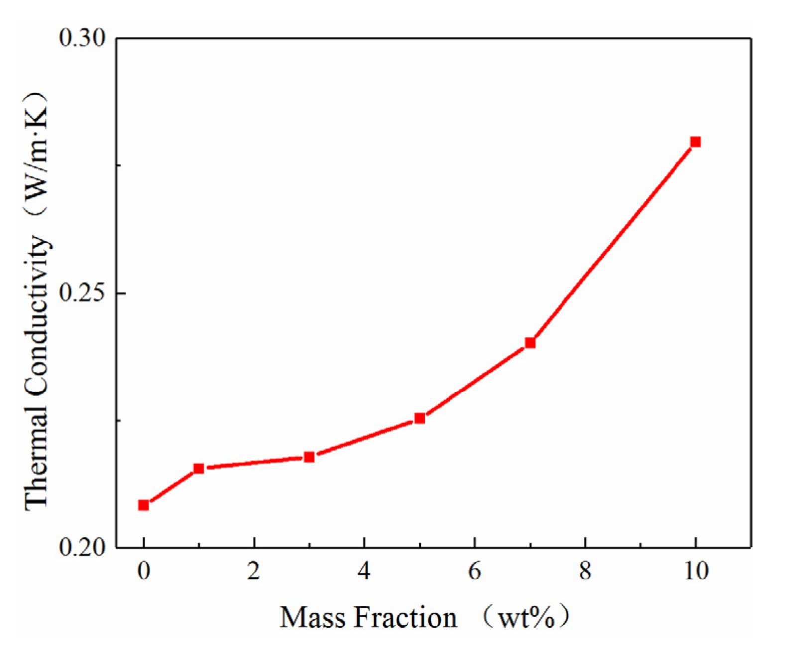
3.1. Thermal Properties
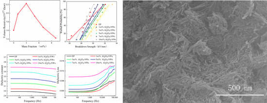
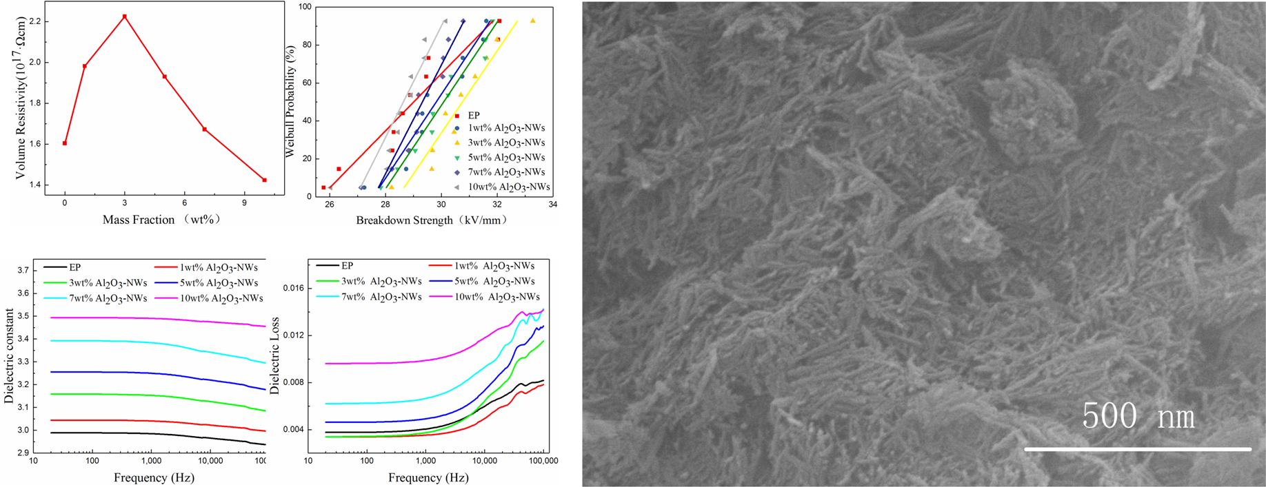
3.2. Volume Resistivity
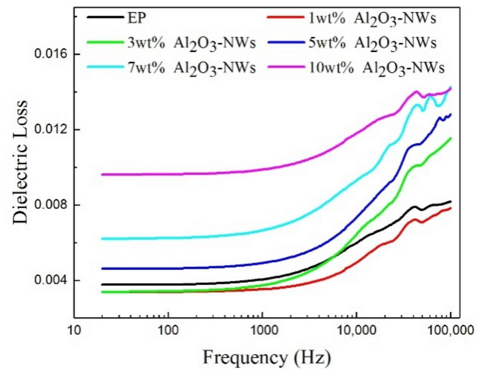
3.3. Dielectric Performance
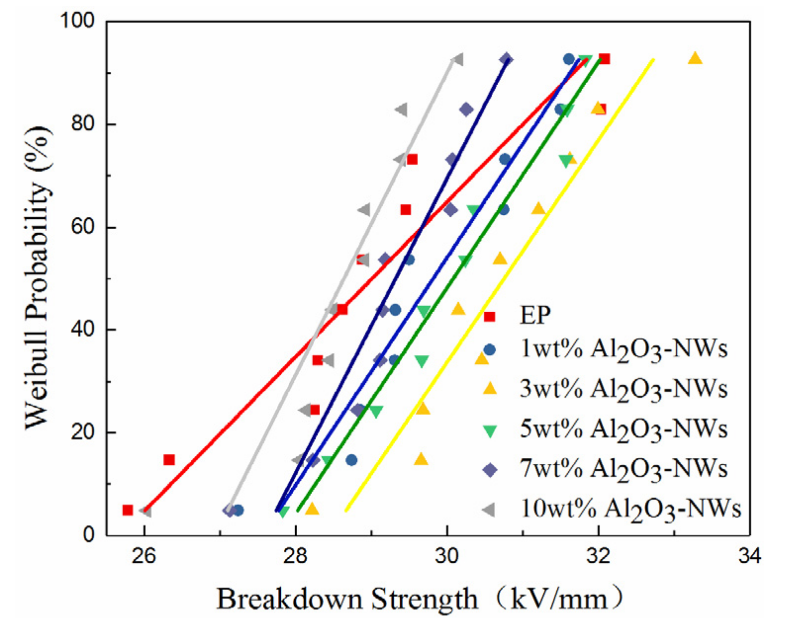
3.4. Breakdown Strength
4. Conclusions
Author Contributions
Funding
Conflicts of Interest
References
- Chlup, Z.; Cerny, M.; Kacha, P.; Hadraba, H.; Strachota, A. Fracture resistance of partially pyrolysedpolysiloxane preceramic polymer matrix composites reinforced by unidirectional basalt fibres. J. Eur. Ceram. Soc. 2020, 40, 4879–4885. [Google Scholar] [CrossRef]
- Tang, Y.; Zhang, P.; Zhu, M.; Li, J.; Li, Y.; Wang, Z.; Huang, L. Temperature effects on the dielectric properties and breakdown performance of h-BN/epoxy composites. Materials 2019, 12, 4112. [Google Scholar] [CrossRef] [Green Version]
- Huang, X.Y.; Jiang, P.K.; Tanaka, T. A review of dielectric polymer composites with high thermal conductivity. IEEE Electr. Insul. Mag. 2011, 27, 8–16. [Google Scholar] [CrossRef]
- McNamara, A.J.; Joshi, Y.; Zhang, Z.M. Characterization of nanostructured thermal interface materials—A review. Int. J. Therm. Sci. 2012, 62, 2–11. [Google Scholar] [CrossRef]
- Dang, Z.; Yuan, J.; Yao, S.; Liao, R. Flexible nanodielectric materialswith high permittivity for power energy storage. Adv. Mater. 2013, 25, 6334–6365. [Google Scholar] [CrossRef] [PubMed]
- Luo, S.; Shen, Y.; Yu, S.; Wang, Y.; Liao, W.; Sun, R.; Wong, C. Construction of a 3D-BaTiO3 network leading to significantly enhanced dielectric permittivity and energy storage density of polymer composites. Energy Environ. Sci. 2017, 10, 137–144. [Google Scholar] [CrossRef]
- Li, Q.; Zhang, G.; Liu, F.; Han, K.; Gadinski, M.R.; Xiong, C.; Wang, Q. Solution-processed ferroelectric terpolymer nanocomposites with high breakdown strength and energy density utilizing boron nitride nanosheets. Energy Environ. Sci. 2015, 8, 922–931. [Google Scholar] [CrossRef]
- Loste, J.; Lopez-Cuesta, J.M.; Billon, L.; Garay, H.; Save, M. Transparent polymer nanocomposites: An overview on their synthesis and advanced properties. Prog. Polym. Sci. 2019, 89, 133–158. [Google Scholar] [CrossRef]
- Mortazav, B.; Benzerara, O.; Meyer, H. Combined molecular dynamics-finite element multiscale modeling of thermal conduction in graphene epoxy nanocomposites. Carbon 2013, 60, 356–365. [Google Scholar] [CrossRef]
- Rubrice, K.; Castel, X.; Himdi, M.; Parneix, P. Dielectric characteristics and microwave absorption of graphene composite materials. Materials 2016, 9, 825. [Google Scholar] [CrossRef]
- Sim, L.C.; Ramanan, S.R.; Ismal, H.; Seetharamu, K.N. Thermal characterization of Al2O3 and ZnO reinforced silicone rubber as thermal pads for heat dissipation purposes. Thermochim. Acta 2005, 430, 155–165. [Google Scholar] [CrossRef]
- Zhou, Y.; Hu, J.; Dang, B.; He, J. Effect of different nanoparticles on tuning electrical properties of polypropylene nanocomposites. IEEE Trans. Dielectr. Electr. Insul. 2017, 24, 1380–1389. [Google Scholar] [CrossRef]
- Yu, J.; Huo, R.; Wu, C.; Wu, X.; Wang, G.; Jiang, P. Influence of interface structure on dielectric properties of epoxy/alumina nanocomposites. Macromol. Res. 2012, 20, 816–826. [Google Scholar] [CrossRef]
- Huang, X.; Zhi, C.; Jiang, P.; Colberg, D.; Bando, Y.; Tanaka, T. polyhedral oligosilsesquioxane-modified boron nitride nanotube based epoxy nanocomposites: an ideal dielectric material with high thermal conductivity. Adv. Funct. Mater. 2013, 23, 1824–1831. [Google Scholar] [CrossRef]
- Yingke, Z.; Hao, Y.; Pingkai, J.; Wu, J.; Zhu, X.; Huang, X. Two-dimensional high-k nanosheets for dielectric polymer nanocomposites with ultrahigh discharged energy density. J. Phys. Chem. C 2018, 122, 18282–18293. [Google Scholar]
- Kochetov, R.; Korobko, A.V.; Andritsch, T.; Morshuis, P.H.F.; Piken, S.J.; Smit, J.J. Modelling of the thermal conductivity in polymer nanocomposites and the impact of the interface between filler and matrix. J. Phys. D Appl. Phys. 2011, 44, 395401. [Google Scholar] [CrossRef]
- Moreira, D.C.; Braga, N.R.; Sphaier, L.A.; Nunes, L.C.S. Size effect on the thermal intensification of alumina-filled nanocomposites. J. Compos. Mater. 2016, 50, 26. [Google Scholar] [CrossRef]
- Anithambigai, P.; Chakravarthii, M.K.D.; Mutharasu, D.; Huong, L.H.; Zahner, T.; Lacey, D.; Kamarulazizi, L. Potential thermally conductive alumina filled epoxy composite for thermal management of high power LEDs. J. Mater. Sci. Mater. Electron. 2016, 28, 856–867. [Google Scholar] [CrossRef]
- Eker, Y.R.; Özcan, M.; Ali Osman Özkan, A.O.; KirKici, H. The influence of Al2O3 and TiO2 additives on the electrical resistivity of epoxy resinased composites at low temperature. Macromol. Mater. Eng. 2019, 304, 1800670. [Google Scholar] [CrossRef]
- Tomaskova, T.; Trnka, P.; Gutten, M.; Korenciak, D. The analysis of the thermal and dielectric properties of high voltage insulating materials with the addition of aluminiumoxide. Arch. Metall. Mater. 2018, 63, 641–646. [Google Scholar]
- Paul, S.; Sind, T.K. A neural network model for predicting the dielectric permittivity of epoxy-aluminum nanocomposite and its experimental validation. IEEE Trans. Compon. Packag. Manuf. Technol. 2015, 5, 1. [Google Scholar] [CrossRef]
- Gong, Y.; Zhou, W.; Sui, X.; Kou, Y.; Chen, Q. Mechanical and dielectric properties of epoxy composites filled with hybrid aluminum particles with binary size distribution. High Perform. Polym. 2019, 31, 1. [Google Scholar] [CrossRef]
- Ramu, T.; Nagamani, H. Alumina and silica based epoxy nano-composites for electrical insulation. IEEE Trans. Dielectr. Electr. Insul. 2014, 21, 236–243. [Google Scholar] [CrossRef]
- Rodrigo, P.R.; Juanes, R.T.; Greus, A.R.; Borrvs, V.A.; Coelho, L.A.F. Breakdown, free-volume and dielectric behavior of the nanodielectric coatings based on epoxy/metal oxides. J. Mater. Sci. Mater. Electron. 2016, 27, 1–15. [Google Scholar]
- Faleh, H.; Al-Mahaidi, R.; Shen, L. Fabrication and characterization of nano-particles-enhanced epoxy. Composites 2012, 43, 3076–3080. [Google Scholar] [CrossRef]
- Wang, H.; Chu, W.; Chen, G. A brief review on measuring methods of thermal conductivity of organic and hybrid thermoelectric materials. Adv. Electron. Mater. 2019, 5, 1900167. [Google Scholar] [CrossRef]
- Kargar, F.; Barani, Z.; Balinskiy, M.; Magana, A.S.; Lewis, J.S.; Balandin, A.A. Dual-functional graphene composites for electromagnetic shielding and thermal management. Adv. Electron. Mater. 2019, 5, 1800558. [Google Scholar] [CrossRef] [Green Version]
- Kargar, F.; Barani, Z.; Salgado, R.; Bishwajit, D.; Ruben Arash, S.; Ece, A.; Roger, L.; Alexander, A.B. Thermal percolation threshold and thermal properties of composites with graphene and boron nitride fillers. ACS Appl. Mater. Interfaces 2018, 10, 3755–37565. [Google Scholar] [CrossRef]
- Barani, Z.; Kargar, F.; Godziszewski, K.; Rehman, A.; Yashchyshyn, Y.; Rumyantsev, S.; Cywinski, G.; Knap, W.; Balandin, A.A. Graphene epoxy-based composites as efficient electromagnetic absorbers in the extremely high-frequency band. ACS Appl. Mater. Interfaces 2020, 12, 28635–28644. [Google Scholar] [CrossRef]
- Tian, X.; Zhang, J.; Guo, D.; Sun, J.; Zhou, Y.; Zhang, W.; Guang, Y. Preparation, characterization and repeated repair ability evaluation of asphalt-based crack sealant containing microencapsulated epoxy resin and curing agent. Constr. Build. Mater. 2020, 256, 119433. [Google Scholar]
- Kochetov, R.; Tsekmes, I.A.; Morshuis, P.H.F. Electrical conductivity, dielectric response and space charge dynamics of an electroactive polymer with and without nanofiller reinforcement. Smart Mater. Struct. 2015, 24, 7. [Google Scholar] [CrossRef]
- Robertson, J. Band offsets of wide-band-gap oxides and implications for future electronic devices. J. Vac. Sci. Technol. B Microelectron. Nanometer. Struct. Process. Meas. Phenom. 2000, 18, 3. [Google Scholar] [CrossRef]
- Huang, X.; Sun, B.; Zhu, Y.; Li, S.; Jiang, P. High-k polymer nanocomposites with 1D filler for dielectric and energy storage applications. Prog. Mater. Sci. 2018, 100, 187–225. [Google Scholar] [CrossRef]
- Singha, S.; Thomas, M.J. Dielectric properties of epoxy nanocomposites. IEEE Trans. Dielectr. Electr. Insul. 2008, 15, 12–23. [Google Scholar] [CrossRef]
- Zhang, T.; Lei, Y.J.; Yin, J.; Du, J.; Yu, P. Effects of pores on dielectric breakdown of alumina ceramics under AC electric field. Ceram. Int. 2019, 45, 13951–13957. [Google Scholar] [CrossRef]


| Mass Fraction | EP | 1 wt% | 3 wt% | 5 wt% | 7 wt% | 10 wt% |
|---|---|---|---|---|---|---|
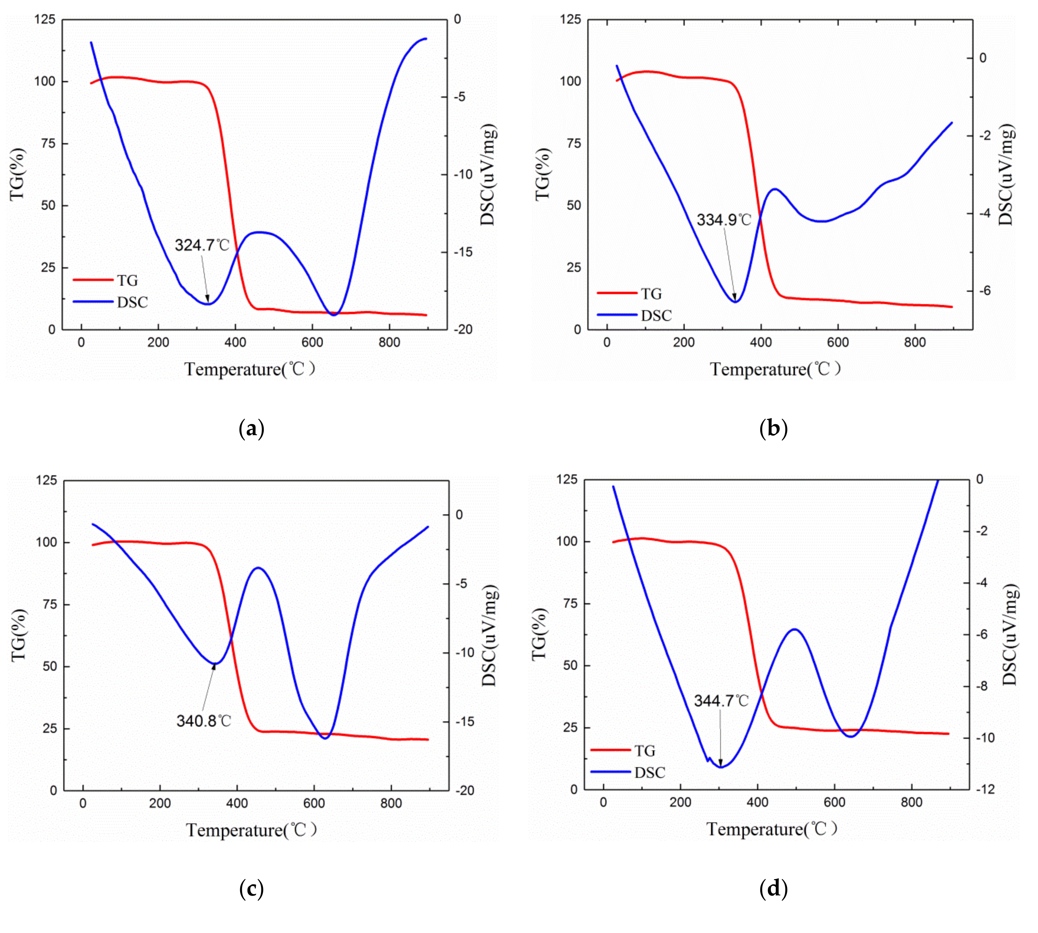
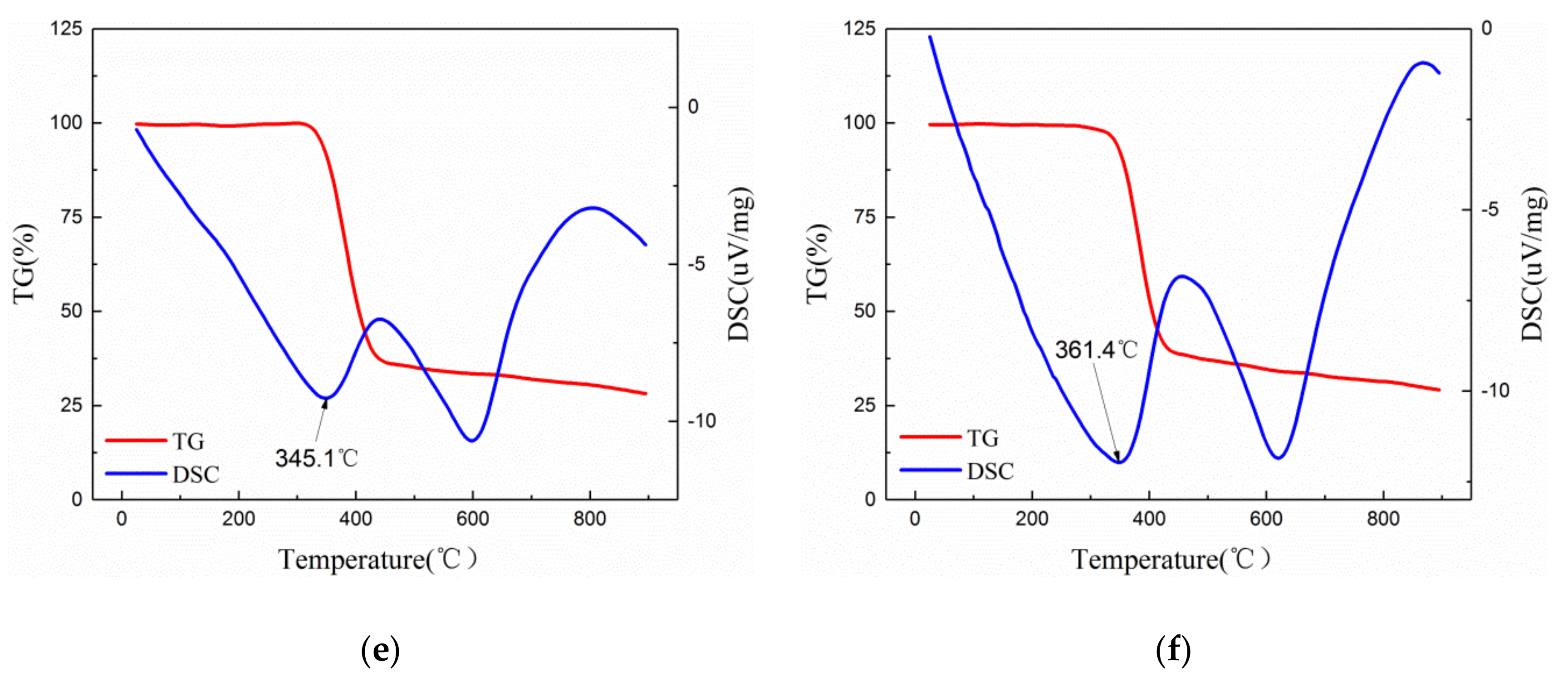
| T10 (°C) | 348.2 | 353.6 | 345.1 | 354.1 | 355.3 | 358.7 |
| T50 (°C) | 387.4 | 392.3 | 395.5 | 396.9 | 401.5 | 403.1 |
| Tm (°C) | 324.7 | 334.9 | 340.8 | 344.7 | 345.1 | 361.4 |
| Mass Fraction | E0 | β |
|---|---|---|
| EP | 29.45712 | 22.4857 |
| 1 wt% | 30.74949 | 24.7283 |
| 3 wt% | 31.20998 | 29.6959 |
| 5 wt% | 30.35178 | 34.4664 |
| 7 wt% | 30.04266 | 29.3359 |
| 10 wt% | 28.91622 | 28.5079 |
© 2020 by the authors. Licensee MDPI, Basel, Switzerland. This article is an open access article distributed under the terms and conditions of the Creative Commons Attribution (CC BY) license (http://creativecommons.org/licenses/by/4.0/).
Share and Cite
Huang, L.; Lv, X.; Tang, Y.; Ge, G.; Zhang, P.; Li, Y. Effect of Alumina Nanowires on the Thermal Conductivity and Electrical Performance of Epoxy Composites. Polymers 2020, 12, 2126. https://0-doi-org.brum.beds.ac.uk/10.3390/polym12092126
Huang L, Lv X, Tang Y, Ge G, Zhang P, Li Y. Effect of Alumina Nanowires on the Thermal Conductivity and Electrical Performance of Epoxy Composites. Polymers. 2020; 12(9):2126. https://0-doi-org.brum.beds.ac.uk/10.3390/polym12092126
Chicago/Turabian StyleHuang, Liangsong, Xitao Lv, Yongzhe Tang, Guanghui Ge, Peng Zhang, and Yuxia Li. 2020. "Effect of Alumina Nanowires on the Thermal Conductivity and Electrical Performance of Epoxy Composites" Polymers 12, no. 9: 2126. https://0-doi-org.brum.beds.ac.uk/10.3390/polym12092126