
Investigation of the Ballistic Performance of GFRP Laminate under 150 m/s High-Velocity Impact: Simulation and Experiment

 , ,
, ,
Abstract
:
1. Introduction
2. Materials and Methods
2.1. High-Velocity Impact Test
2.1.1. Materials
2.1.2. Test Method
2.2. Numerical Modeling
2.2.1. Constitutive Model
2.2.2. Intralaminar Damage Model
2.2.3. Interlaminar Damage Model
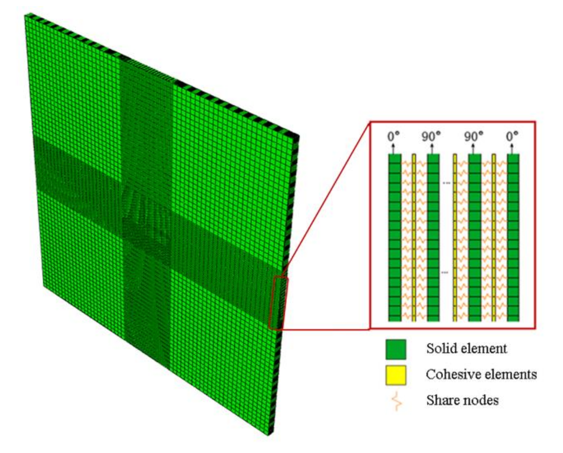
2.2.4. Numerical Model
3. Results
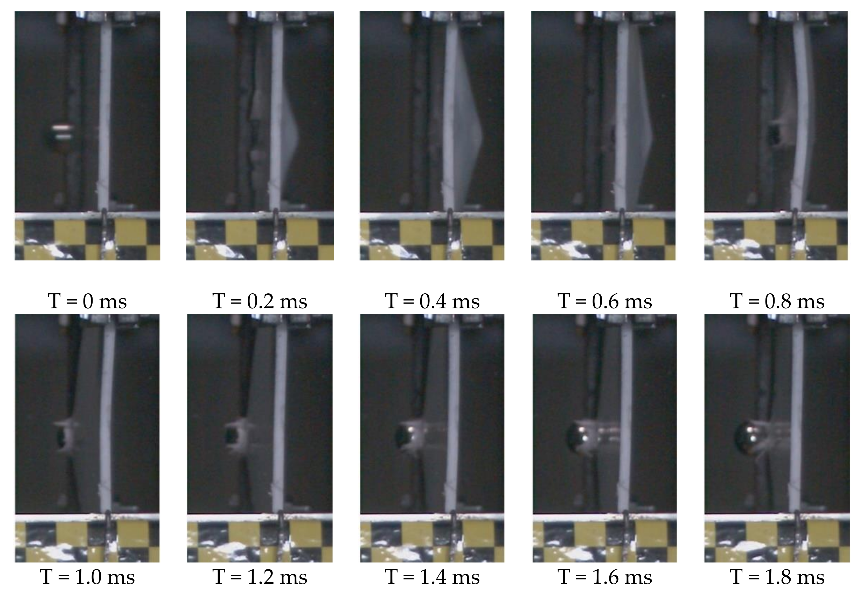
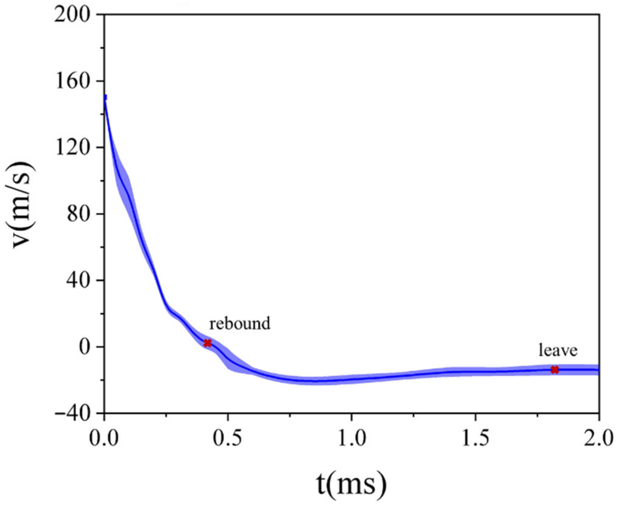
3.1. High-Velocity Impact Test Results
3.2. Numerical Results and Comparisons with the Experiments
4. Discussion
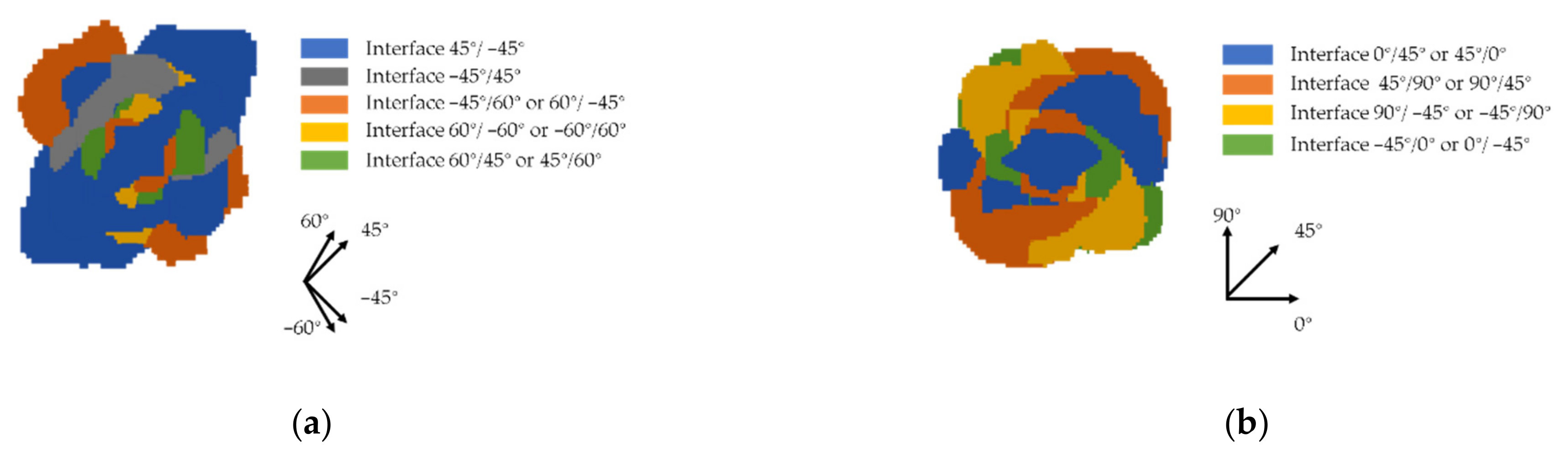
4.1. Delamination
4.2. Ballistic Resistance of GFRP Laminates with Varying Layouts
5. Conclusions
- ●
- Determination of the material model: Through the analysis of the experiment results, the finite element model combining the strain rate effect and Hashin failure criterion was determined.
- ●
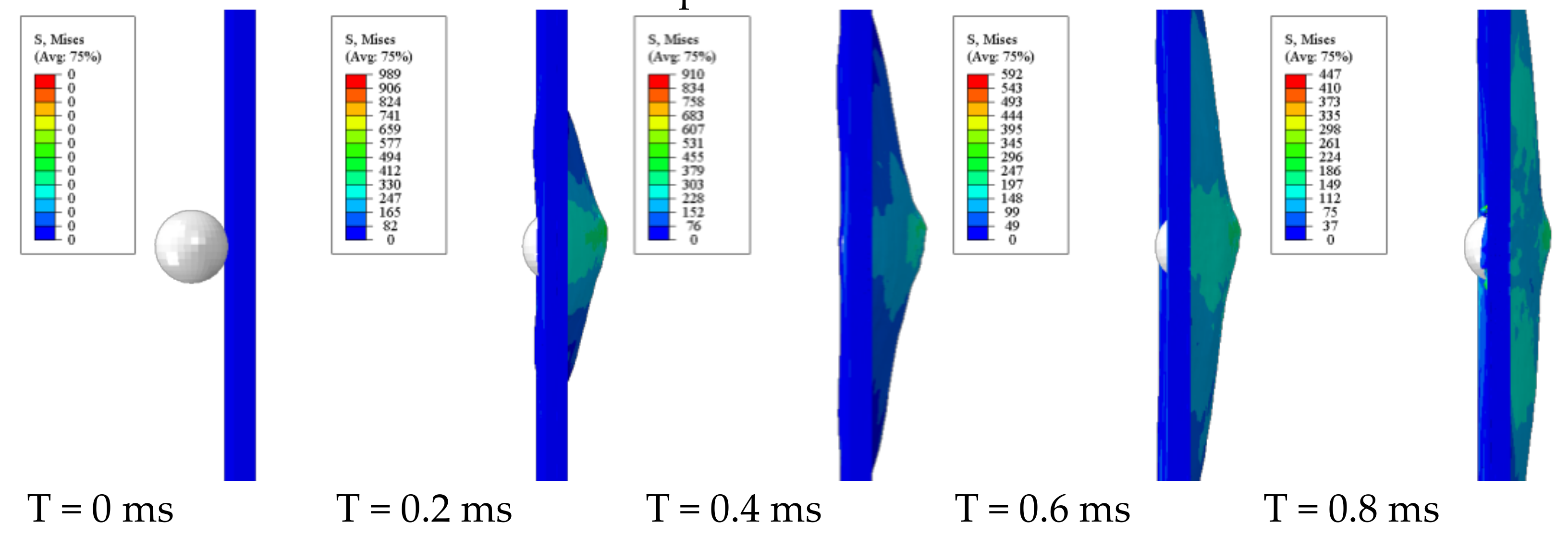
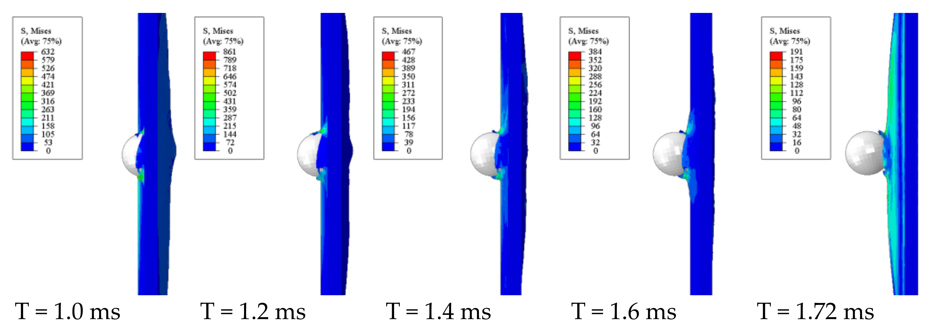
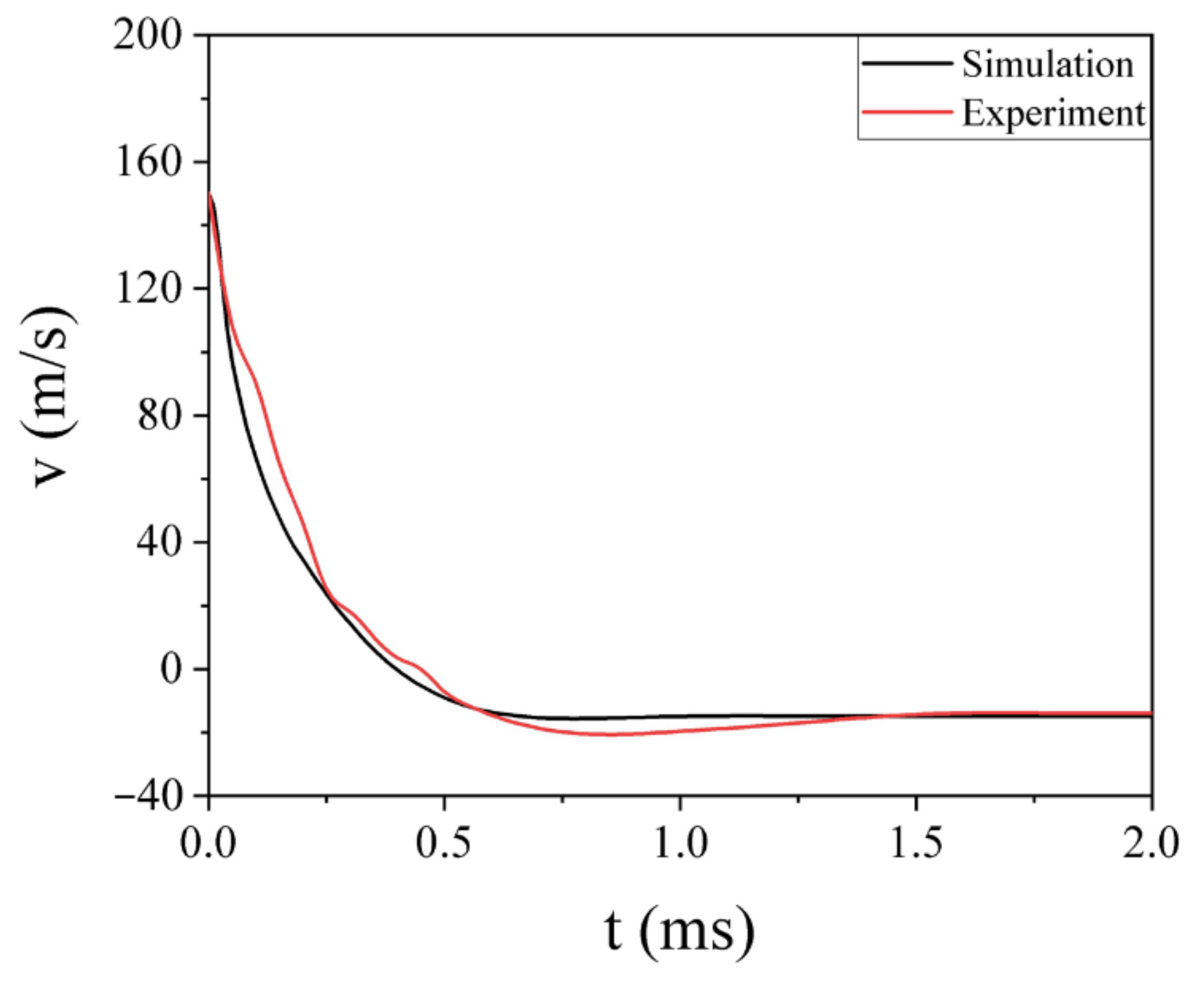
- Impact response of the GFRP laminate and numerical simulations based on the FE: The FE simulation was established by the material model selected in the paper. The results presented good agreement between the simulation and experiment, which confirmed that the selected material model was reasonable.
- ●
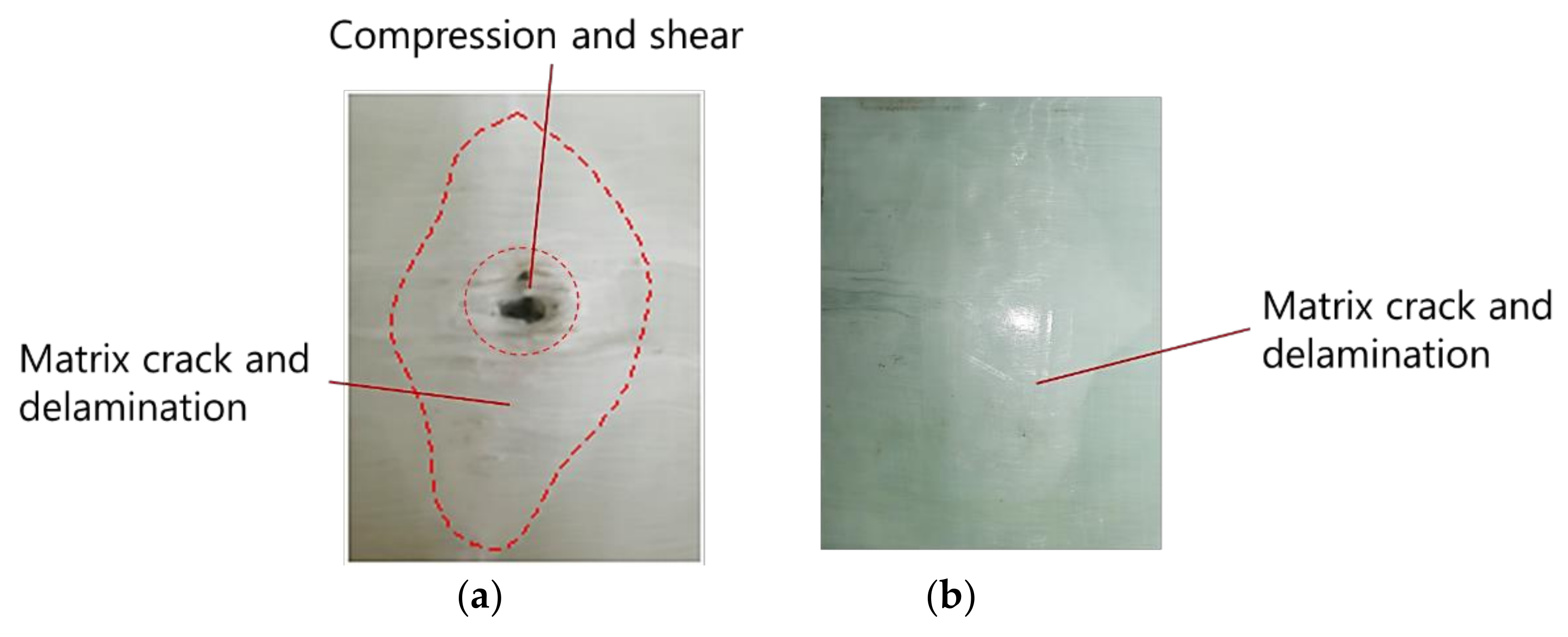
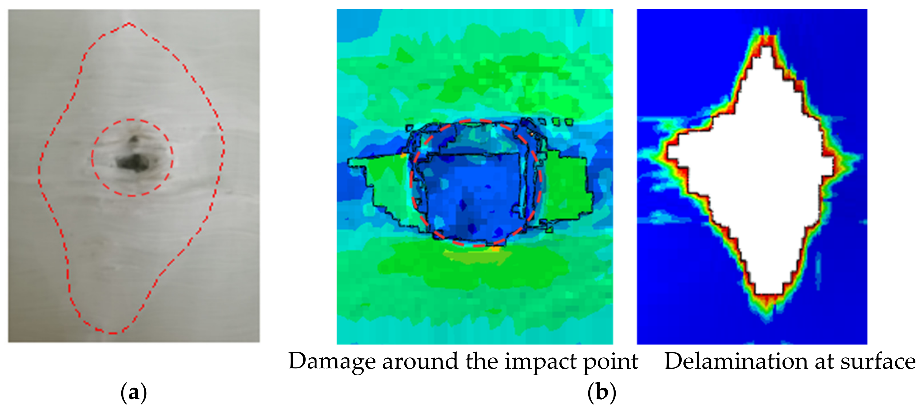
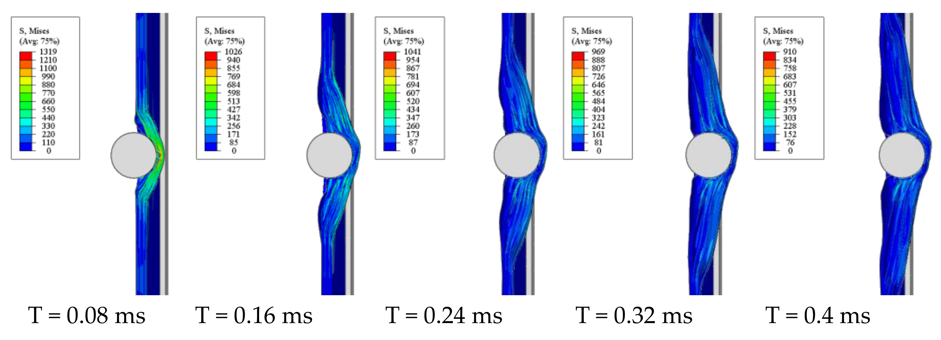
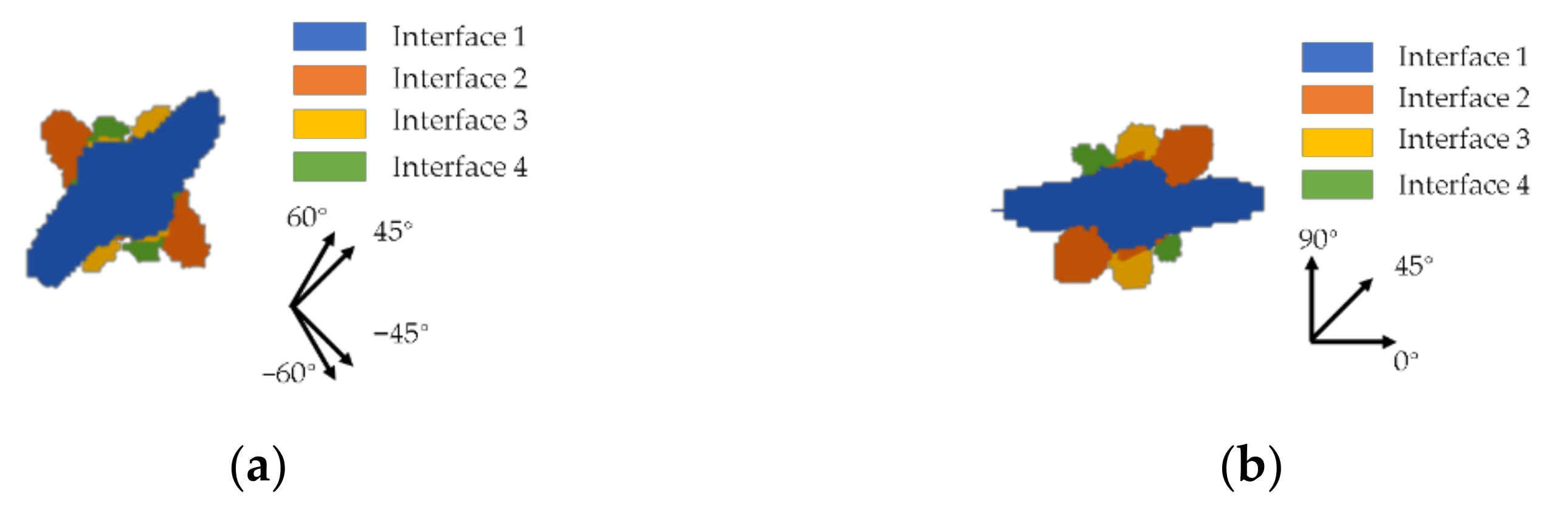
- Analysis of the intralaminar and interlaminar damages: (1) Different types of failures were produced for the high-velocity impact test, including the compression damage below the projectile and fiber breakage on the periphery of the projectile caused by normal stress and shear stress, respectively. The delamination happened in both the front and rear layers. (2) The expansion of delamination mainly occurred in the penetration stage, and the delamination between the rear layers was greater than the front ones, which was due to the difference in damage type and deformation between them.
- ●
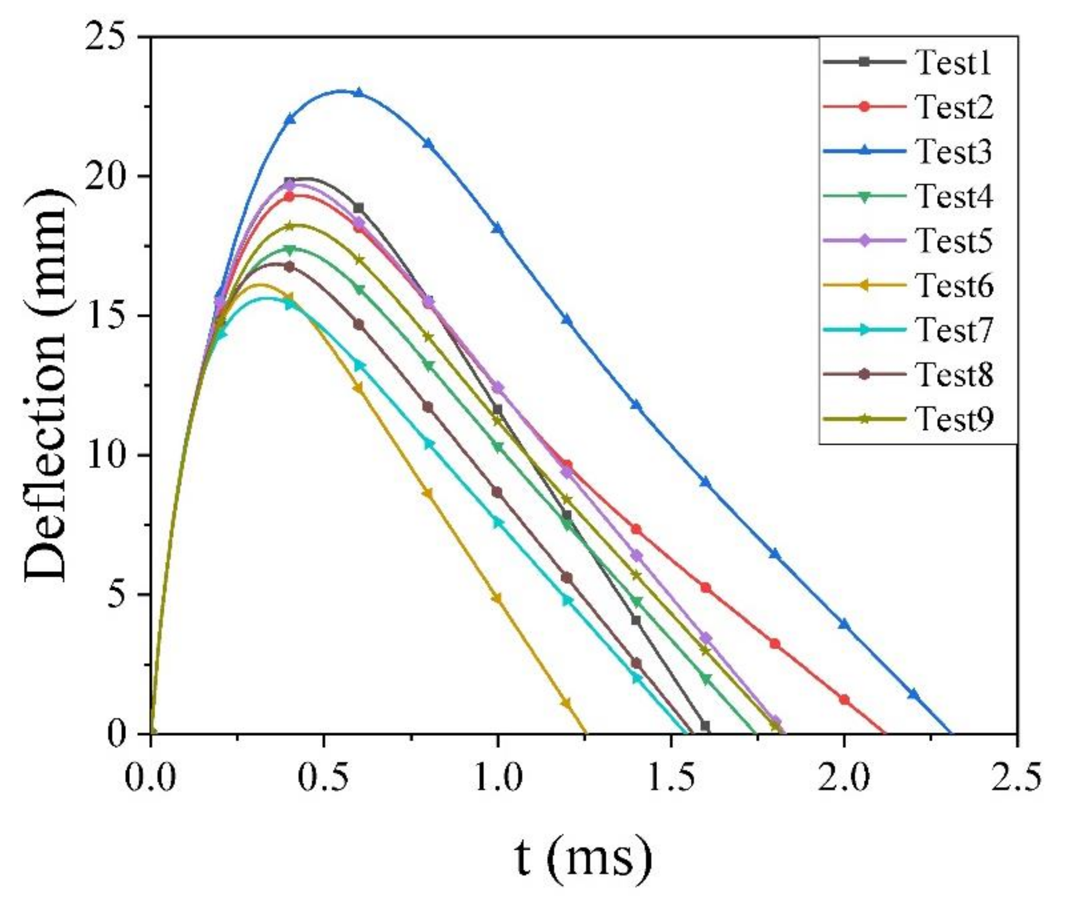
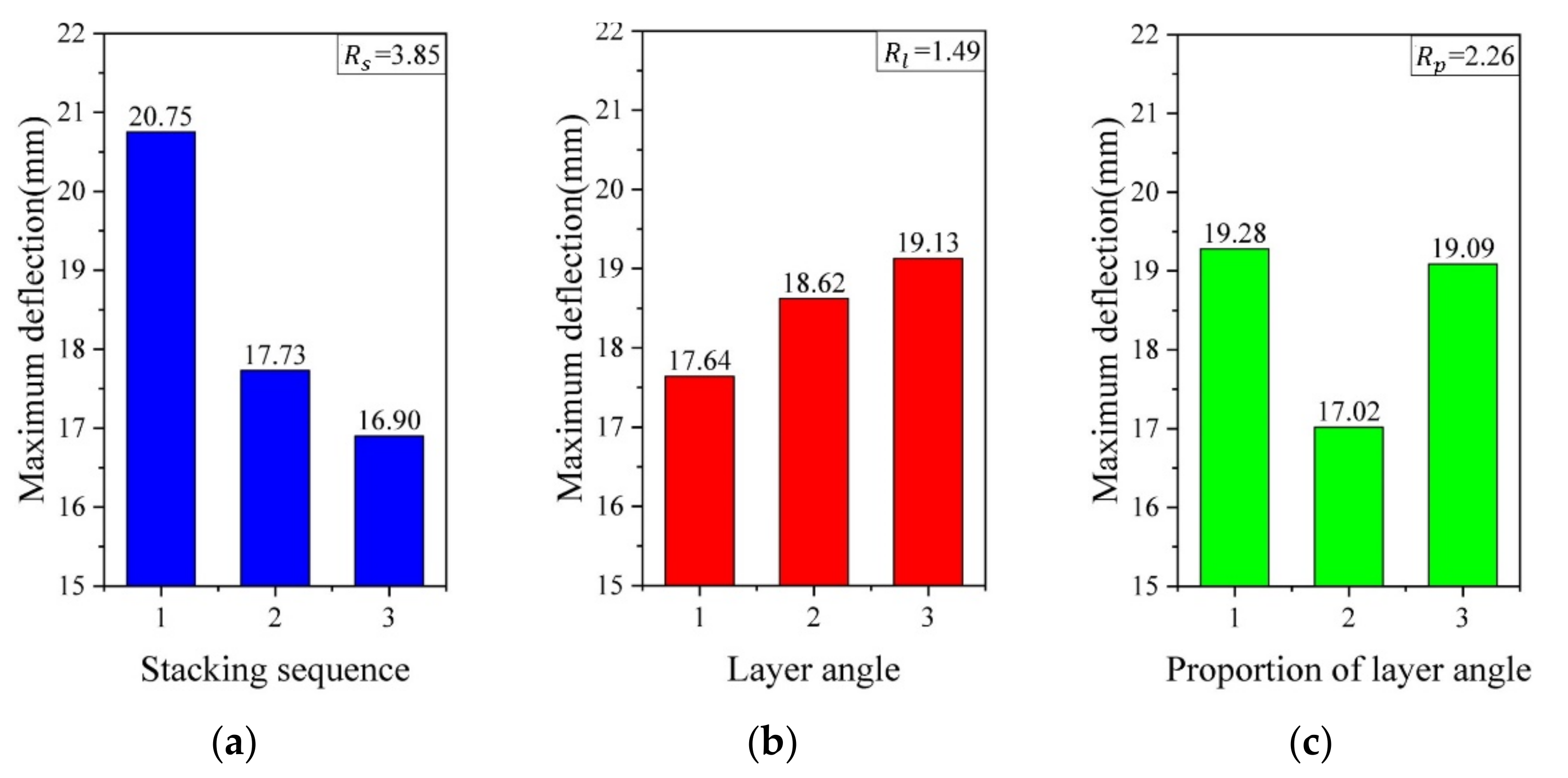
- Analysis of the deformation: (1) For laminates with different layouts, it can be concluded that the stacking sequence contributes a stronger influence on the maximum deflection of the GFRP laminates. The proportions of the layer angle are the second-most important factor, while the layer angle is the least one. The best combination scheme was inferred as , and the maximum deformation of it reduced laminate 3 by 32.16%. (2) The larger overlapping area of the delamination damage resulted in a higher deflection, so there was no recommendation for the laminate with a too-small interface angle. The quasi-isotope showed a better ballistic performance.
Author Contributions
Funding
Institutional Review Board Statement
Informed Consent Statement
Data Availability Statement
Conflicts of Interest
References
- Wang, K.; Li, S.; Rao, Y.; Wu, Y.; Peng, Y.; Yao, S.; Zhang, H.; Ahzi, S. Flexure Behaviors of ABS-based Composites Containing Carbon and Kevlar Fibers by Material Extrusion 3D Printing. Polymers 2019, 11, 1878. [Google Scholar] [CrossRef] [PubMed] [Green Version]
- Chen, X.; Peng, Y.; Chen, C.; Li, J.; Wang, K.; Wang, T. Mechanical behavior and texture evolution of aluminum alloys subjected to strain path changes: Experiments and modeling. Mater. Sci. Eng. A 2019, 757, 32–41. [Google Scholar] [CrossRef]
- Balcıa, O.; Çobanb, O.; Borab, M.Ö.; Akagündüzc, E.; Yalçin, E.B. Experimental investigation of single and repeated impacts for repaired honeycomb sandwich structures. Mater. Sci. Eng. 2017, 682, 23–30. [Google Scholar] [CrossRef]
- Cai, X.; Pan, P.; Zhu, J.; Gu, R. The Analysis of the Aerodynamic Character and Structural Response of Large-Scale Wind Turbine Blades. Energies 2013, 6, 3134–3148. [Google Scholar] [CrossRef] [Green Version]
- Bakis, C.E.; Bank, L.C.; Brown, V.L.; Cosenza, E.; Davalos, J.F.; Lesko, J.J.; Machida, A.; Rizkalla, S.H.; Triantafillou, T.C. Fiber-Reinforced Polymer Composites for Construction—State-of-the-Art Review. J. Compos. Constr. 2002, 6, 73–87. [Google Scholar] [CrossRef] [Green Version]
- Christian, S.; Billington, S. Mechanical response of PHB- and cellulose acetate natural fiber-reinforced composites for construction applications. Compos. Part B: Eng. 2011, 42, 1920–1928. [Google Scholar] [CrossRef]
- Xie, S.; Wang, N.; Yang, W.; Li, H. Energy absorption performance of thin-walled metal plate due to upheaval deformation based on experiments and numerical simulation. Thin-Walled Struct. 2018, 131, 258–273. [Google Scholar] [CrossRef]
- Gao, G.J. The energy distribution of a train impact process based on the active-passive energy-absorption method. Transp. Safe Environ. 2019, 1, 54–67. [Google Scholar]
- Peng, Y.; Ma, W.; Wang, S.; Wang, K.; Gao, G. Investigation of the fracture behaviors of windshield laminated glass used in high-speed trains. Compos. Struct. 2019, 207, 29–40. [Google Scholar] [CrossRef]
- Peng, Y.; Wu, Y.; Li, S.; Wang, K.; Yao, S.; Liu, Z.; Garmestani, H. Tailorable rigidity and energy-absorption capability of 3D printed continuous carbon fiber reinforced polyamide composites. Compos. Sci. Technol. 2020, 199, 108337. [Google Scholar] [CrossRef]
- Peng, Y.; Wu, Y.; Wang, K.; Gao, G.; Ahzi, S. Synergistic reinforcement of polyamide-based composites by combination of short and continuous carbon fibers via fused filament fabrication. Compos. Struct. 2019, 207, 232–239. [Google Scholar] [CrossRef]
- VanDerKlok, A.; Stamm, A.; Dorer, J.; Hu, E.; Auvenshine, M.; Pereira, J.M.; Xiao, X. An experimental investigation into the high velocity impact responses of S2-glass/SC15 epoxy composite panels with a gas gun. Int. J. Impact Eng. 2018, 111, 244–254. [Google Scholar] [CrossRef]
- Todo, M.; Takahashi, K.; Béguelin, P.; Kausch, H. Strain-rate dependence of the tensile fracture behaviour of woven-cloth reinforced polyamide composites. Compos. Sci. Technol. 2000, 60, 763–771. [Google Scholar] [CrossRef]
- Wang, K.; Ahzi, S.; Boumbimba, R.M.; Bahlouli, N.; Addiego, F.; Rémond, Y. Micromechanical modeling of the elastic behavior of polypropylene based organoclay nanocomposites under a wide range of temperatures and strain rates/frequencies. Mech. Mater. 2013, 64, 56–68. [Google Scholar] [CrossRef]
- Wang, K.; Xie, X.; Wang, J.; Zhao, A.; Peng, Y.; Rao, Y. Effects of infill characteristics and strain rate on the deformation and failure properties of additively manufactured polyamide-based composite structures. Results Phys. 2020, 18, 103346. [Google Scholar] [CrossRef]
- Papadakis, N.; Reynolds, N.; Pharaoh, M.; Wood, P.; Smith, G. Strain rate effects on the shear mechanical properties of a highly oriented thermoplastic composite material using a contacting displacement measurement methodology–Part A: Elasticity and shear strength. Compos. Sci. Technol. 2004, 64, 729–738. [Google Scholar] [CrossRef]
- Morua, M.F.S.F.; Marques, A.T. Prediction of low velocity impact damage in carbon-epoxy laminates. Compos. Part A Appl. Sci. Manuf. 2002, 33, 361–368. [Google Scholar] [CrossRef]
- Ansari, M.; Chakrabarti, A. Ballistic Performance of Unidirectional Glass Fiber Laminated Composite Plate under Normal and Oblique Impact. Procedia Eng. 2017, 173, 161–168. [Google Scholar] [CrossRef]
- Aktaş, M.M.; Atas, C.; Muratİçten, B.; Karakuzu, R. An experimental investigation of the impact response of composite laminates. Compos. Struct. 2009, 87, 307–313. [Google Scholar] [CrossRef]
- Jordan, J.B.; Naito, C.J. An experimental investigation of the effect of nose shape on fragments penetrating GFRP. Int. J. Impact Eng. 2014, 63, 63–71. [Google Scholar] [CrossRef]
- Sikarwar, R.S.; Velmurugan, R.; Gupta, N. Influence of fiber orientation and thickness on the response of glass/epoxy composites subjected to impact loading. Compos. Part B Eng. 2014, 60, 627–636. [Google Scholar] [CrossRef]
- Chen, Y.; Pang, B.; Zheng, W.; Peng, K. Experimental investigation on normal and oblique ballistic impact behavior of fiber metal laminates. J. Reinf. Plast. Compos. 2013, 32, 1769–1778. [Google Scholar] [CrossRef]
- Zhang, H.; Wu, Y.; Wang, K.; Peng, Y.; Wang, D.; Yao, S.; Wang, J. Materials selection of 3D-printed continuous carbon fiber reinforced composites considering multiple criteria. Mater. Des. 2020, 196, 109140. [Google Scholar] [CrossRef]
- Ansari, M.M.; Chakrabarti, A. Influence of projectile nose shape and incidence angle on the ballistic perforation of laminated glass fiber composite plate. Compos. Sci. Technol. 2017, 142, 107–116. [Google Scholar] [CrossRef]
- Ansari, M.M.; Chakrabarti, A. Progressive damage of GFRP composite plate under Ballistic Impact: Experimental and numerical Study. Polym. Polym. Compos. 2016, 24, 7. [Google Scholar]
- Ansari, M.; Chakrabarti, A.; Iqbal, M. An experimental and finite element investigation of the ballistic performance of laminated GFRP composite target. Compos. Part B Eng. 2017, 125, 211–226. [Google Scholar] [CrossRef]
- Zhang, C.; Zhu, Q.; Curiel-Sosa, J.L.; Bui, T.Q. Ballistic performance and damage simulation of fiber metal laminates under high-velocity oblique impact. Int. J. Damage Mech. 2020, 29, 1011–1034. [Google Scholar] [CrossRef]
- Higuchi, R.; Okabe, T.; Yoshimura, A.; Tay , T.E. Progressive failure under high-velocity impact on composite laminates: Experiment and phenomenological mesomodeling. Eng. Fract. Mech. 2017, 178, 346–361. [Google Scholar] [CrossRef]
- Du, B.; Chen, L.; Tan, J.; Zhou, H.; Zhao, Y.; Wu, W.; Li, W.; Fang, D.; Chen, L. Fabrication and bending behavior of thermoplastic composite curved corrugated sandwich beam with interface enhancement. Int. J. Mech. Sci. 2018, 149, 101–111. [Google Scholar] [CrossRef]
- Hashin, Z. Failure Criteria for Unidirectional Fiber Composites. J. Appl. Mech. 1980, 47, 329–334. [Google Scholar] [CrossRef]
- Hashin, Z.; Rotem, A. A Fatigue Failure Criterion for Fiber Reinforced Materials. J. Compos. Mater. 1973, 7, 448–464. [Google Scholar] [CrossRef] [Green Version]
- Xu, M.; Yang, Y.; Lei, H.; Wang, P.; Li, X.; Zhang, Z.; Fang, D. Dynamic response of fiber metal laminates subjected to localized high impulse blast loading. Compos. Struct. 2020, 243, 112216. [Google Scholar] [CrossRef]
- Sharma, A.P.; Khan, S.H.; Parameswaran, V. Experimental and numerical investigation on the uni-axial tensile response and failure of fiber metal laminates. Compos. Part B Eng. 2017, 125, 259–274. [Google Scholar] [CrossRef]
- Zhikharev, M.; Sapozhnikov, S.; Kudryavtsev, O.; Zhikharev, V. Effect of tensile preloading on the ballistic properties of GFRP. Compos. Part B Eng. 2019, 168, 524–531. [Google Scholar] [CrossRef]
- Catalanotti, G.; Camanho, P.; Ghys, P.; Marques, A. Experimental and numerical study of fastener pull-through failure in GFRP laminates. Compos. Struct. 2011, 94, 239–245. [Google Scholar] [CrossRef] [Green Version]
- Xiaojuan, J.; Qi, O. Optimal design of point-focusing shear vertical wave electromagnetic ultrasonic transducers based on orthogonal test method. IEEE Sens. J. 2018, 18, 8064–8073. [Google Scholar]
- Carraro, P.; Maragoni, L.; Quaresimin, M. Stiffness degradation of symmetric laminates with off-axis cracks and delamination: An analytical model. Int. J. Solids Struct. 2021, 213, 50–62. [Google Scholar] [CrossRef]
- Sztefek, P.; Olsson, R. Tensile stiffness distribution in impacted composite laminates determined by an inverse method. Compos. Part A Appl. Sci. Manuf. 2008, 39, 1282–1293. [Google Scholar] [CrossRef]


| Material | Diameter (mm) | Destiny (kg/) | Mass (g) | Elastic Modulus (GPa) | Poisson’s Ratio |
|---|---|---|---|---|---|
| Stainless Steel | 20 | 7980 | 33 | 206 | 0.30 |
| Parameter | |||||
|---|---|---|---|---|---|
| Value | 28,000 | 3400 | 0.064 | 946 | 1598 |
| Parameter | |||||
| Value | 746 | 160 | 15 | 50 | 16 |
| Parameter | |||||
|---|---|---|---|---|---|
| Value | 15 | 16 | 2.08 | 1.44 | 1.45 |
| Factors | Stacking Sequence | Layer Angles | Proportions of Different Layer Angle Pairs |
|---|---|---|---|
| Level 1 | AB | 1:3 | |
| Level 2 | AC | 1:1 | |
| Level 3 | BC | 3:1 |
| No. | Stacking Sequence | Layer Angles | Proportions of Layer Angle | Layout Sequence | Maximum Deflection |
|---|---|---|---|---|---|
| 1 | 1 | 1 | 1 | 19.92 | |
| 2 | 1 | 2 | 2 | 19.31 | |
| 3 | 1 | 3 | 3 | 23.04 | |
| 4 | 2 | 1 | 3 | 17.39 | |
| 5 | 2 | 2 | 1 | 19.69 | |
| 6 | 2 | 3 | 2 | 16.11 | |
| 7 | 3 | 1 | 2 | 15.63 | |
| 8 | 3 | 2 | 3 | 16.85 | |
| 9 | 3 | 3 | 1 | 18.24 |
Publisher’s Note: MDPI stays neutral with regard to jurisdictional claims in published maps and institutional affiliations. |
© 2021 by the authors. Licensee MDPI, Basel, Switzerland. This article is an open access article distributed under the terms and conditions of the Creative Commons Attribution (CC BY) license (http://creativecommons.org/licenses/by/4.0/).
Share and Cite
Chen, F.; Peng, Y.; Chen, X.; Wang, K.; Liu, Z.; Chen, C. Investigation of the Ballistic Performance of GFRP Laminate under 150 m/s High-Velocity Impact: Simulation and Experiment. Polymers 2021, 13, 604. https://0-doi-org.brum.beds.ac.uk/10.3390/polym13040604
Chen F, Peng Y, Chen X, Wang K, Liu Z, Chen C. Investigation of the Ballistic Performance of GFRP Laminate under 150 m/s High-Velocity Impact: Simulation and Experiment. Polymers. 2021; 13(4):604. https://0-doi-org.brum.beds.ac.uk/10.3390/polym13040604
Chicago/Turabian StyleChen, Fengyan, Yong Peng, Xuanzhen Chen, Kui Wang, Zhixiang Liu, and Chao Chen. 2021. "Investigation of the Ballistic Performance of GFRP Laminate under 150 m/s High-Velocity Impact: Simulation and Experiment" Polymers 13, no. 4: 604. https://0-doi-org.brum.beds.ac.uk/10.3390/polym13040604