Utilization of Bracing Arms as Additional Reinforcement in Pultruded Glass Fiber-Reinforced Polymer Composite Cross-Arms: Creep Experimental and Numerical Analyses

 ,
, 

Abstract
:1. Introduction
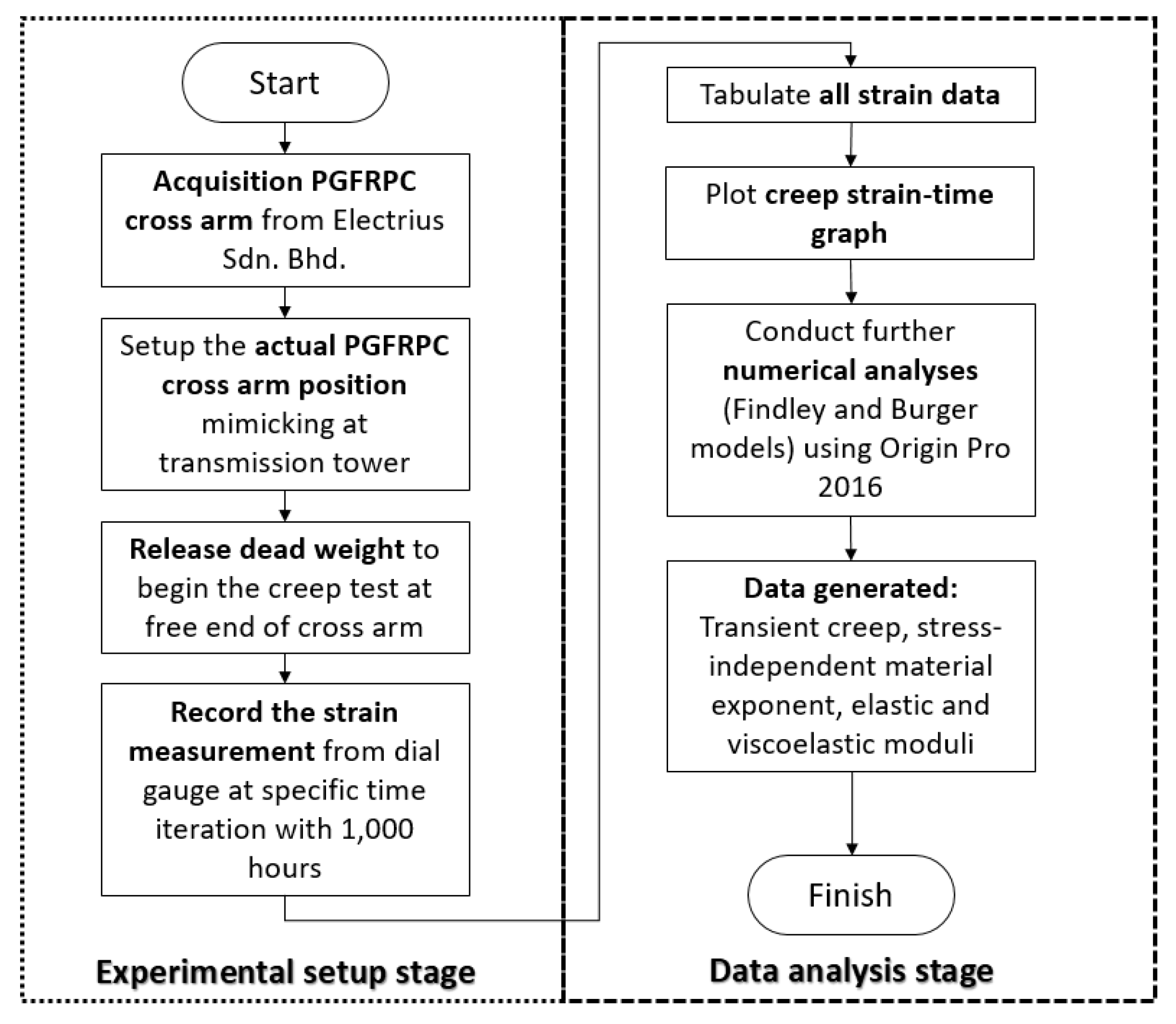
2. Methodology
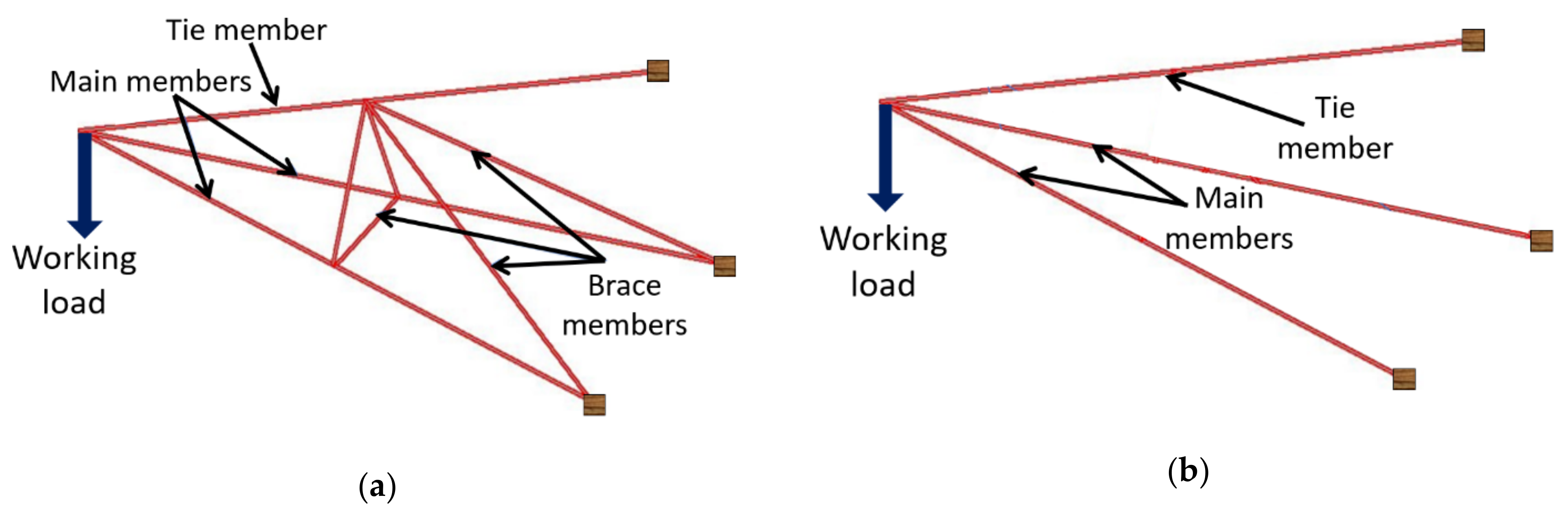
2.1. Materials
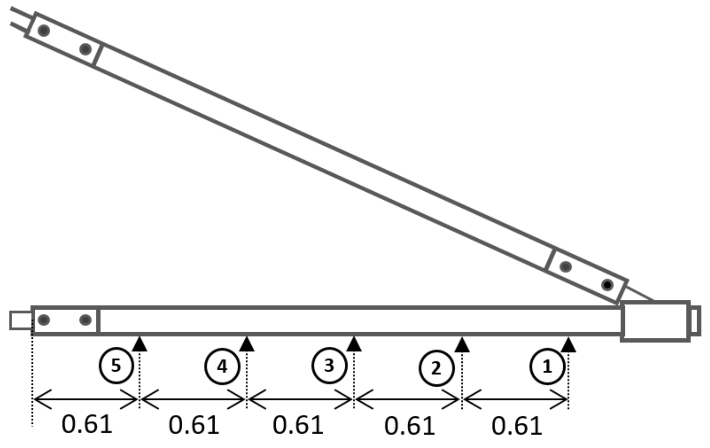
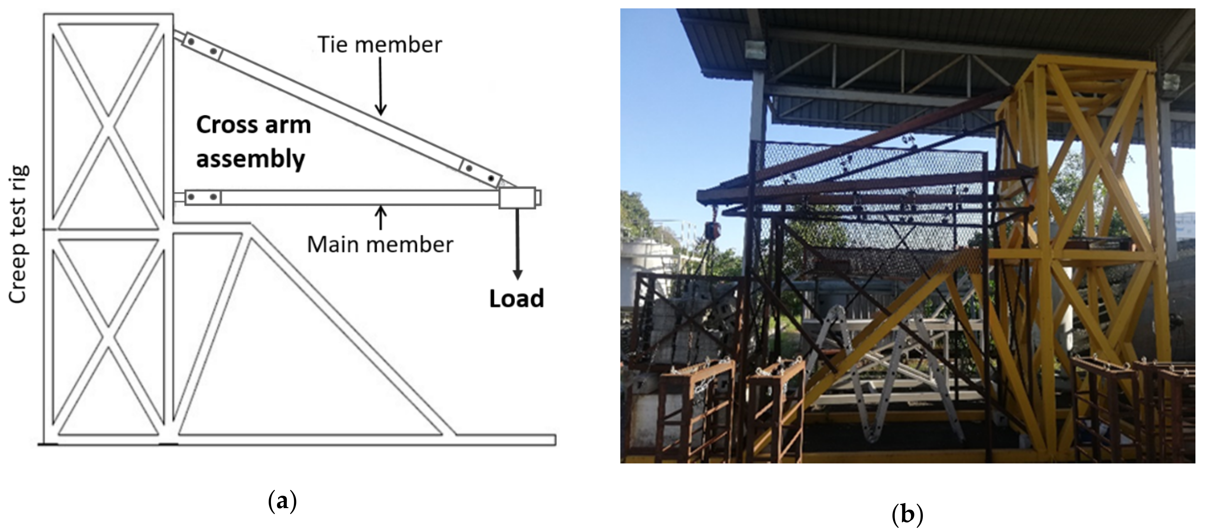
2.2. Methods
2.2.1. Creep Properties of Cross-Arms
2.2.2. Constitutive Creep Models
3. Results and Discussion
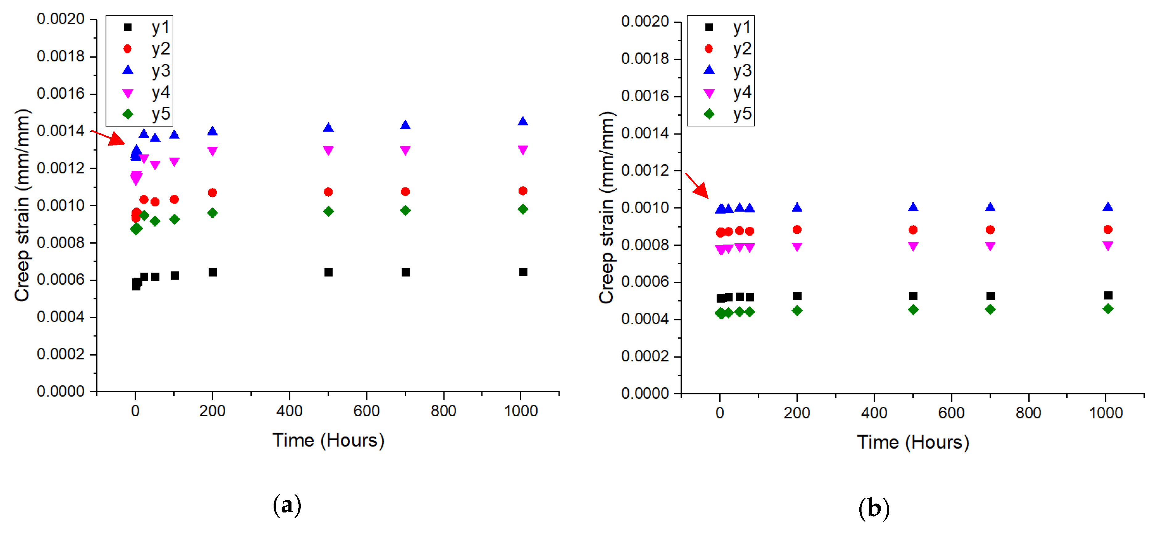
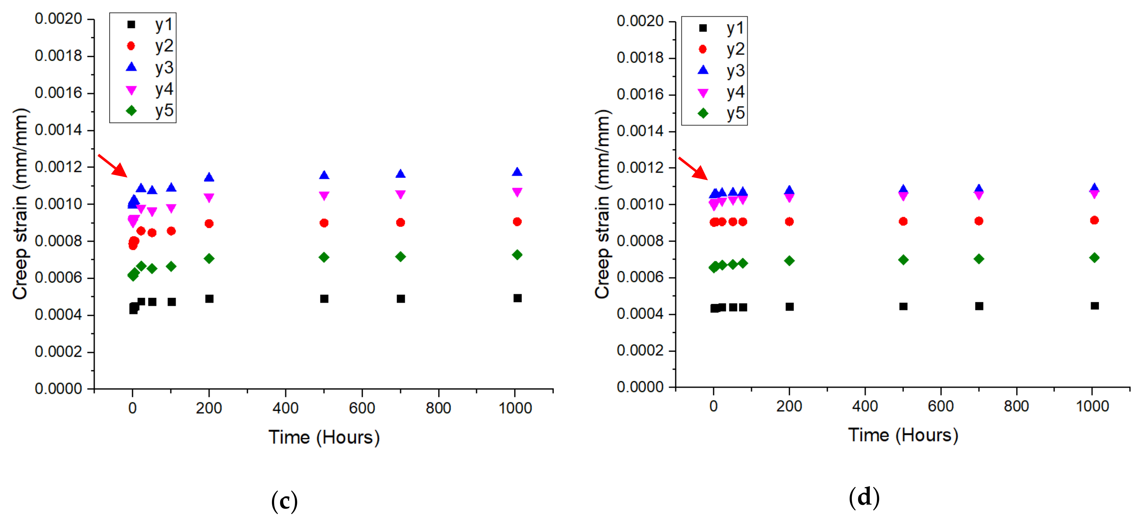
3.1. Strain-Time Curve
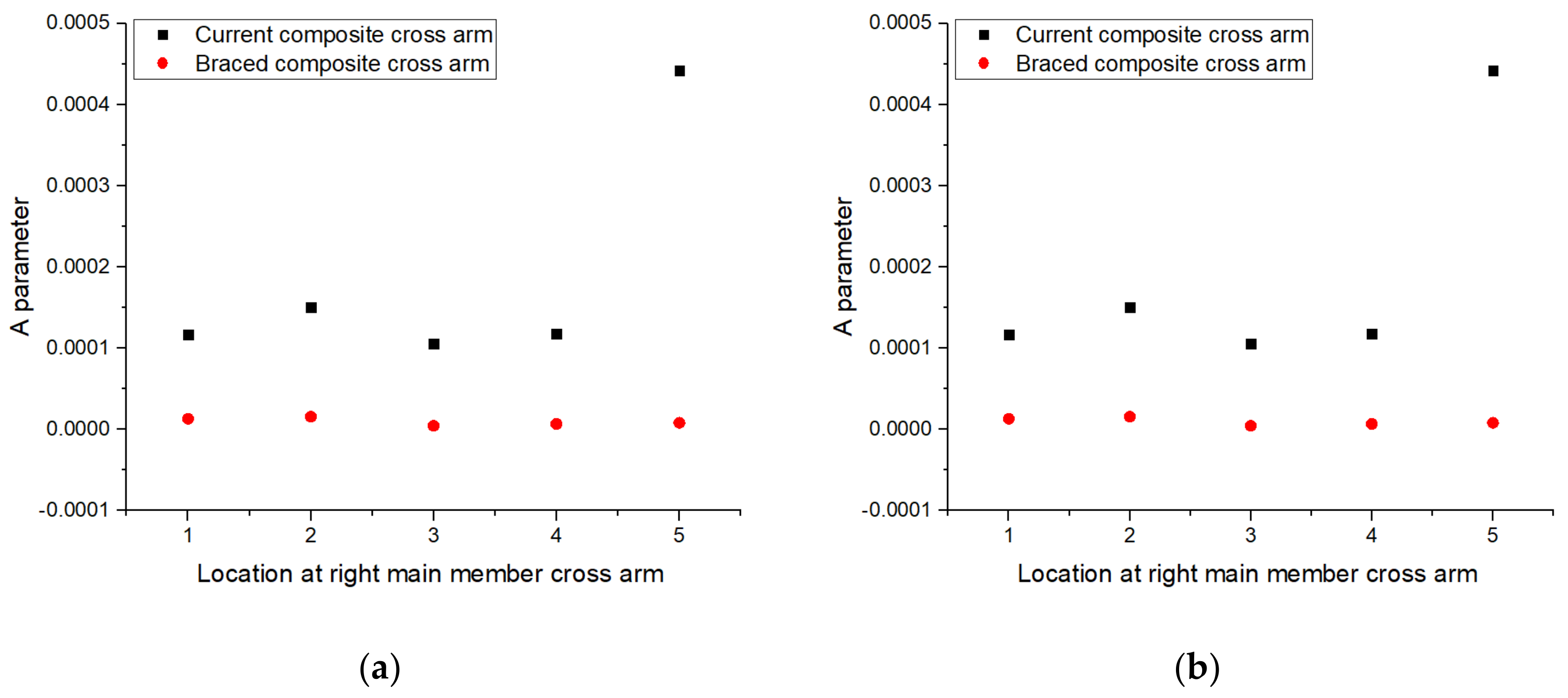
3.2. Findley Power Law Model
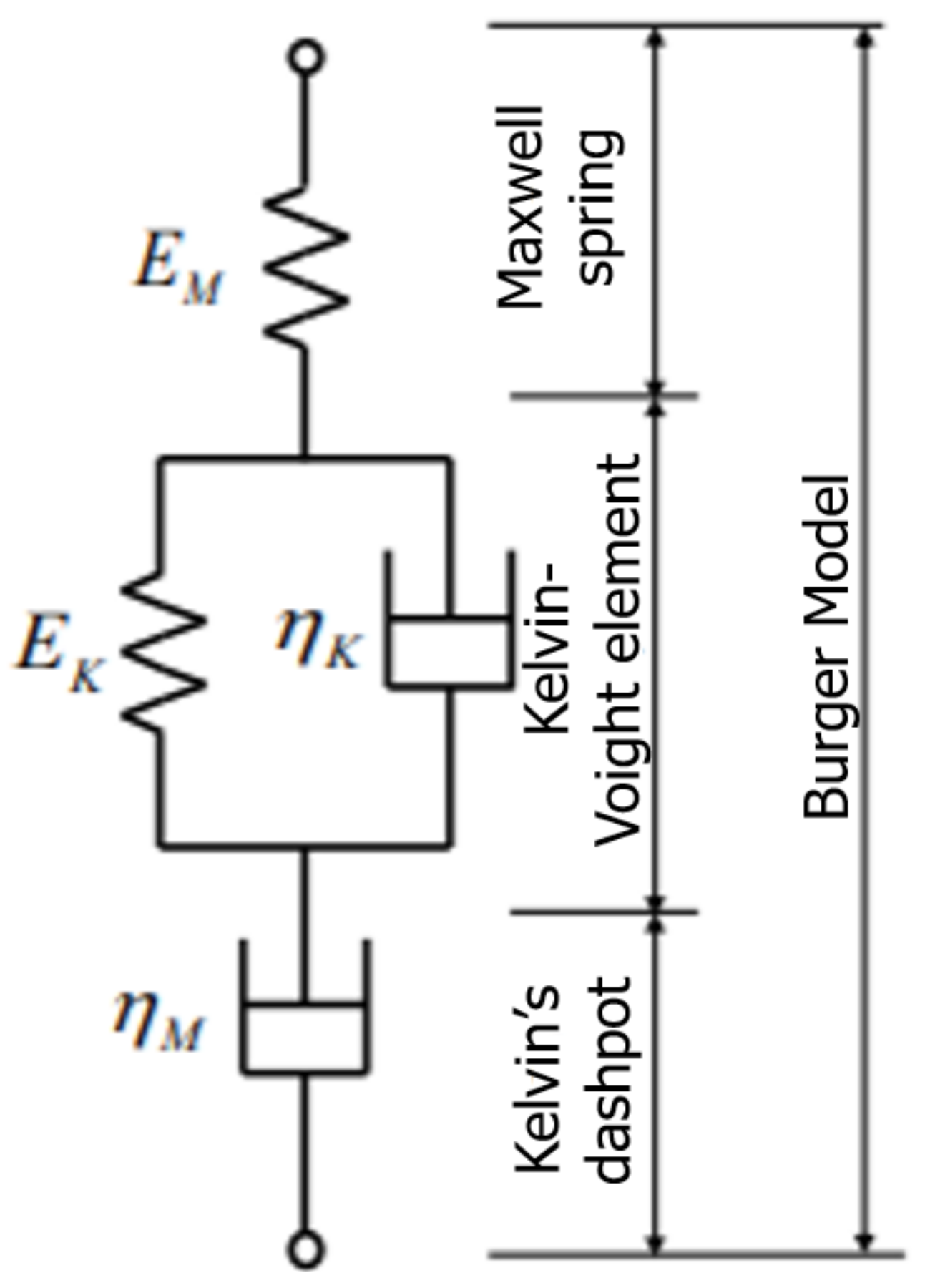
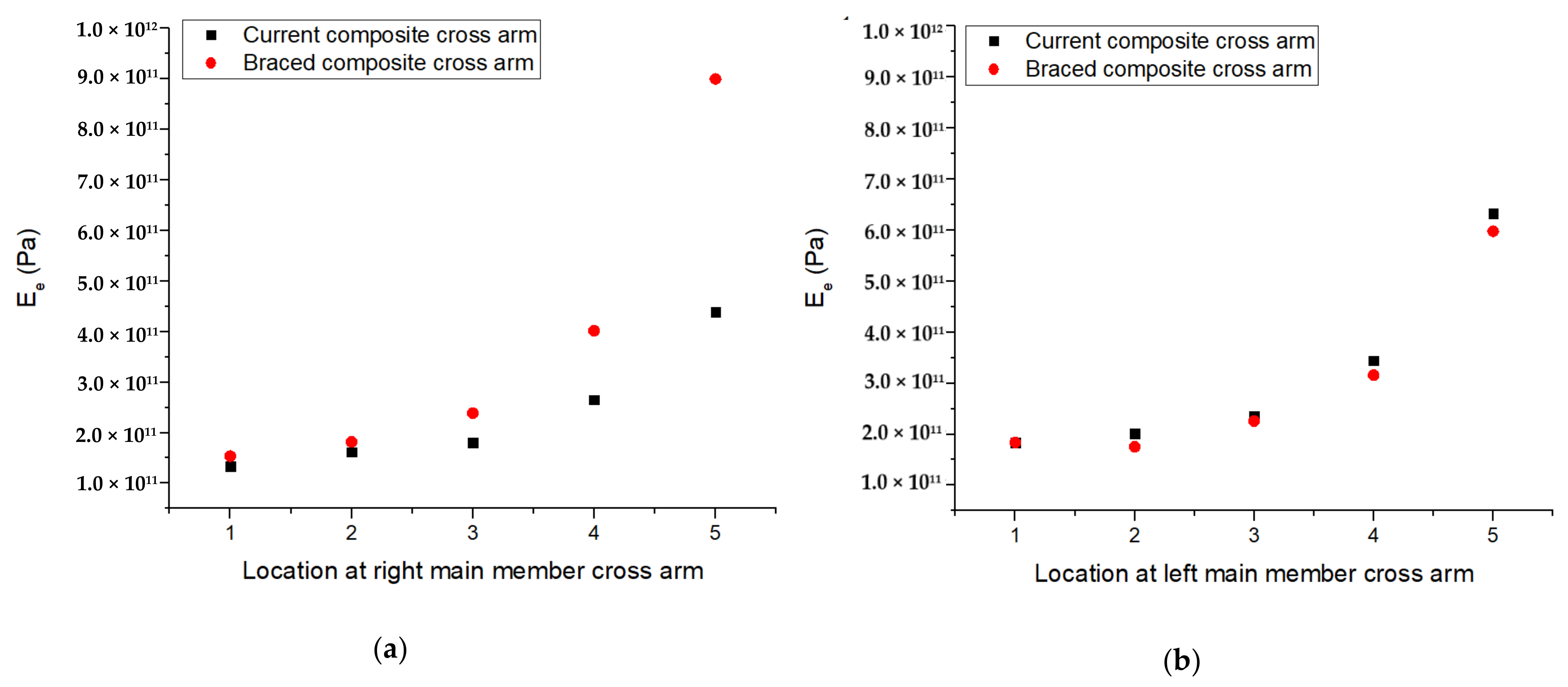
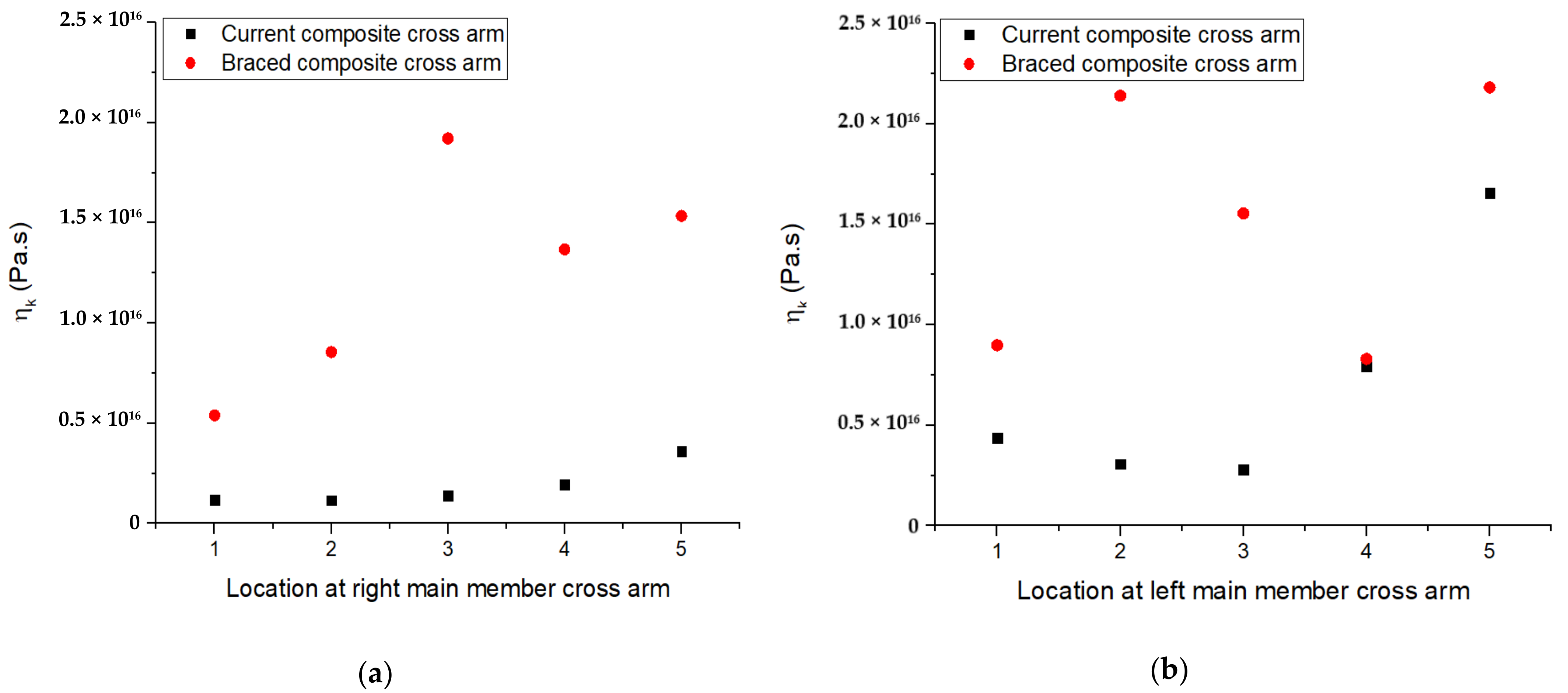
3.3. Burger Model
3.4. Creep Models Accuracy and Validation
4. Conclusions
Author Contributions
Funding
Institutional Review Board Statement
Informed Consent Statement
Data Availability Statement
Acknowledgments
Conflicts of Interest
References
- Rawi, I.M.; Ab-Kadir, M.Z.A. Investigation on the 132 kV overhead lines lightning-related flashovers in Malaysia. In Proceedings of the 2015 International Symposium on Lightning Protection (XIII SIPDA), Balneario Camboriu, Brazil, 28 September–2 October 2015; Institute of Electrical and Electronics Engineers (IEEE): Piscataway, NJ, USA, 2015; pp. 239–243. [Google Scholar]
- Itam, Z.; Ishak, Z.M.; Yusof, Z.M.; Salwi, N.; Zainoodin, M.M. Effect on the temperature behavior of glass fiber reinforced polymer (GFRP) in various application—A review. AIP Conf. Proc. 2018, 2031, 1–5. [Google Scholar] [CrossRef]
- Selvaraj, M.; Kulkarni, S.M.; Babu, R.R. Analysis and experimental testing of a built-up composite cross arm in a transmission line tower for mechanical performance. Compos. Struct. 2013, 96, 1–7. [Google Scholar] [CrossRef]
- Rahman, M.S.A. Wood and fiberglass crossarm performance against lightning strikes on transmission towers. In Proceedings of the International Conference on Power Systems Transient (IPST), Seoul, Korea, 26–29 June 2017; Sung-Kyun-Kwan University: Seoul, Korea, 2017; pp. 1–6. [Google Scholar]
- Ilyas, R.A.; Sapuan, S.; Atiqah, A.; Ibrahim, R.; Abral, H.; Ishak, M.R.; Zainudin, E.S.; Nurazzi, N.M.; Atikah, M.S.N.; Ansari, M.N.M.; et al. Sugar palm (Arenga pinnata (Wurmb.) Merr) starch films containing sugar palm nanofibrillated cellulose as reinforcement: Water barrier properties. Polym. Compos. 2019, 41, 459–467. [Google Scholar] [CrossRef]
- Ilyas, R.; Sapuan, S.; Norrrahim, M.N.F.; Yasim-Anuar, T.A.T.; Kadier, A.; Kalil, M.S.; Atikah, M.; Ibrahim, R.; Asrofi, M.; Abral, H.; et al. Nanocellulose/Starch Biopolymer Nanocomposites: Processing, Manufacturing, and Applications. In Advanced Processing, Properties, and Applications of Starch and Other Bio-Based Polymers; Elsevier BV: Amsterdam, The Netherlands, 2020; pp. 65–88. [Google Scholar]
- Ilyas, R.; Sapuan, S.; Atikah, M.; Asyraf, M.; Rafiqah, S.A.; Aisyah, H.; Nurazzi, N.M.; Norrrahim, M. Effect of hydrolysis time on the morphological, physical, chemical, and thermal behavior of sugar palm nanocrystalline cellulose (Arenga pinnata (Wurmb.) Merr). Text. Res. J. 2020, 004051752093239. [Google Scholar] [CrossRef]
- Ilyas, R.A.; Sapuan, M.S.; Norizan, M.N.; Norrrahim, M.N.F.; Ibrahim, R.; Atikah, M.S.N.; Huzaifah, M.R.M.; Radzi, A.M.; Izwan, S.; Azammi, A.M.N.; et al. Macro to nanoscale natural fiber composites for automotive components: Research, development, and application. In Biocomposite and Synthetic Composites for Automotive Applications; Sapuan, M.S., Ilyas, R.A., Eds.; Woodhead Publishing Series: Amsterdam, The Netherland, 2020. [Google Scholar]
- Forestry Department of Peninsular Malaysia. Annual Report 2018: JPSM; Forestry Department of Peninsular Malaysia: Kuala Lumpur, Malaysia, 2018.
- Abu-Bakar, M.S.; Mohamad, D.; Ishak, Z.M.; Yusof, Z.M.; Salwi, N. Durability control of moisture degradation in GFRP cross arm transmission line towers. AIP Conf. Proc. 2018, 2031, 020027. [Google Scholar] [CrossRef]
- Sapuan, S.M. A Conceptual Design of the Concurrent Engineering Design System for Polymeric-Based Composite Automotive Pedals. Am. J. Appl. Sci. 2005, 2, 514–525. [Google Scholar] [CrossRef] [Green Version]
- Ishak, N.M.; Malingam, S.D.; Mansor, M.R. The application of TRIZ on natural fibre metal laminate to reduce the weight of the car front hood. J. Braz. Soc. Mech. Sci. Eng. 2018, 40, 105. [Google Scholar] [CrossRef]
- Asyraf, M.R.M.; Rafidah, M.; Ishak, M.R.; Sapuan, S.; Yidris, N.; Ilyas, R.; Razman, M.R. Integration of TRIZ, morphological chart and ANP method for development of FRP composite portable fire extinguisher. Polym. Compos. 2020, 41, 2917–2932. [Google Scholar] [CrossRef]
- Mazani, N.; Sapuan, S.; Sanyang, M.; Atiqah, A.; Ilyas, R. Design and Fabrication of a Shoe Shelf from Kenaf Fiber Reinforced Unsaturated Polyester Composites. In Lignocellulose for Future Bioeconomy; Elsevier BV: Amsterdam, The Netherlands, 2019; pp. 315–332. [Google Scholar]
- Ilyas, R.; Sapuan, S.; Asyraf, M.; Atikah, M.; Ibrahim, R.; Dele-Afolabi, T.; Hazrol, M. Introduction to Biofiller-Reinforced Degradable Polymer Composites. In Biofiller-Reinforced Biodegradable Polymer Composites; Informa UK Limited: London, UK, 2020; pp. 1–23. [Google Scholar]
- Omran, A.A.B.; Mohammed, A.A.B.A.; Sapuan, S.M.; Ilyas, R.A.; Asyraf, M.R.M.; Koloor, S.S.R.; Petrů, M. Micro- and Nanocellulose in Polymer Composite Materials: A Review. Polymers (Basel) 2021, 13, 231. [Google Scholar] [CrossRef]
- Alsubari, S.; Zuhri, M.Y.M.; Sapuan, S.M.; Ishak, M.R.; Ilyas, R.A.; Asyraf, M.R.M. Potential of Natural Fiber Reinforced Polymer Composites in Sandwich Structures: A Review on Its Mechanical Properties. Polymers (Basel) 2021, 13, 423. [Google Scholar] [CrossRef]
- Mohamad, D.; Syamsir, A.; Beddu, S.; Abas, A.; Ng, F.C.; Razali, M.F.; Seman, S.A.H.A. Numerical Study of Composite Fiberglass Cross Arms under Statics Loading and Improvement with Sleeve Installation. IOP Conf. Ser. Mater. Sci. Eng. 2019, 530, 012027. [Google Scholar] [CrossRef]
- Mohamad, D.; Syamsir, A.; Sa’Don, S.N.; Zahari, N.M.; Seman, S.A.H.A.; Razali, M.F.; Abas, A.; Ng, F.C. Stacking Sequence Effects on Performance of Composite Laminate Structure Subjected To Multi-Axial Quasi-Static Loading. IOP Conf. Ser. Mater. Sci. Eng. 2019, 530, 1–6. [Google Scholar] [CrossRef]
- Mohamad, D.; Syamsir, A.; Beddu, S.; Kamal, N.L.M.; Zainoodin, M.M.; Razali, M.F.; Abas, A.; Seman, S.A.H.A.; Ng, F.C. Effect of Laminate Properties on the Failure of Cross Arm Structure under Multi-Axial Load. IOP Conf. Ser. Mater. Sci. Eng. 2019, 530, 012029. [Google Scholar] [CrossRef]
- Mohamad, D.; Syamsir, A.; Itam, Z.; A Bakar, H.; Abas, A.; Ng, F.C.; Razali, M.F.; Seman, S.A.H.A. Numerical Simulation on the Statics Deformation Study of Composite Cross Arms of Different Materials and Configurations. IOP Conf. Ser. Mater. Sci. Eng. 2019, 530. [Google Scholar] [CrossRef]
- Asyraf, M.; Ishak, M.R.; Sapuan, S.; Yidris, N. Conceptual design of multi-operation outdoor flexural creep test rig using hybrid concurrent engineering approach. J. Mater. Res. Technol. 2020, 9, 2357–2368. [Google Scholar] [CrossRef]
- Asyraf, M.; Ishak, M.R.; Sapuan, S.; Yidris, N. Conceptual design of creep testing rig for full-scale cross arm using TRIZ-Morphological chart-analytic network process technique. J. Mater. Res. Technol. 2019, 8, 5647–5658. [Google Scholar] [CrossRef]
- Asyraf, M.R.M.; Ishak, M.R.; Sapuan, S.M.; Yidris, N.; Ilyas, R.A.; Rafidah, M.; Razman, M.R. Evaluation of design and simulation of creep test rig for full-scale cross arm structure. Adv. Civ. Eng. 2020, 6980918. [Google Scholar] [CrossRef]
- Asyraf, M.R.M.; Ishak, M.R.; Razman, M.R.; Chandrasekar, M. Fundamentals of creep, testing methods and development of test rig for the full-scale crossarm: A review. J. Teknol. 2019, 81, 155–164. [Google Scholar] [CrossRef] [Green Version]
- Asyraf, M.R.M.; Ishak, M.R.; Sapuan, S.; Yidris, N.; Ilyas, R. Woods and composites cantilever beam: A comprehensive review of experimental and numerical creep methodologies. J. Mater. Res. Technol. 2020, 9, 6759–6776. [Google Scholar] [CrossRef]
- Asyraf, M.R.M.; Ishak, M.R.; Sapuan, S.M.; Yidris, N.; Shahroze, R.M.; Johari, A.N.; Rafidah, M.; Ilyas, R.A. Creep test rig for cantilever beam: Fundamentals, prospects and present views. J. Mech. Eng. Sci. 2020, 14, 6869–6887. [Google Scholar] [CrossRef]
- Nadhirah, A.; Mohamad, D.; Zainoodin, M.; Nabihah, S.; Mubin, N.; Itam, Z.; Mansor, H.; Kamal, N.M.; Muda, Z.C.; Nasional, U.T.; et al. Properties of fiberglass crossarm in transmission tower—A review. Int. J. App. Eng. Res. 2017, 12, 15228–15233. [Google Scholar]
- Fairuz, A.M.; Sapuan, S.M.; Zainudin, E.S.; Jaafar, C.N. Polymer composite manufacturing using a pultrusion process: A review. Am. J. Appl. Sci. 2014, 11, 1798–1810. [Google Scholar] [CrossRef]
- Jahangiri, T.; Wang, Q.; da Silva, F.F.; Bak, C.L. Fiber Reinforced Plastic (FRP) Composite Selection for the Composite Cross-Arm Core. In Lecture Notes in Electrical Engineering; Springer Science and Business Media LLC: Berlin/Heidelberg, Germany, 2019; Volume 557, pp. 15–65. [Google Scholar]
- Hunt, J.F.; Zhang, H.; Huang, Y. Analysis of Cantilever-Beam Bending Stress Relaxation Properties of Thin Wood Composites. Bioresource 2015, 10, 3131–3145. [Google Scholar] [CrossRef] [Green Version]
- Feng, S.H.; Zhao, Y.K. The summary of wood stress relaxation properties and its influencing factors. WoodProc. Mach. 2010, 25, 39–40. [Google Scholar]
- Liu, H.W. Mechanics of Materials; China Machine Press: Beijing, China, 2004. [Google Scholar]
- Fu, H.; Dun, M.; Wang, H.; Wang, W.; Ou, R.; Wang, Y.; Liu, T.; Wang, Q. Creep response of wood floor-high-density polyethylene/laminated veneer lumber coextruded composites. Constr. Build. Mater. 2020, 237, 117499. [Google Scholar] [CrossRef]
- Findley, W.N. Creep characteristics of plastics. Symp. Plast. ASTM 1944, 118–134. [Google Scholar]
- Perez, C.J.; Alvarez, V.A.; Vázquez, A. Creep behaviour of layered silicate/starch–polycaprolactone blends nanocomposites. Mater. Sci. Eng. A 2008, 480, 259–265. [Google Scholar] [CrossRef]
- Chandra, P.K.; Sobral, P.J.D.A. Calculation of viscoelastic properties of edible films: Application of three models. Food Sci. Technol. 2000, 20, 250–256. [Google Scholar] [CrossRef]
- Hao, A.; Chen, Y.; Chen, J.Y. Creep and recovery behavior of kenaf/polypropylene nonwoven composites. J. Appl. Polym. Sci. 2014, 131, 8864–8874. [Google Scholar] [CrossRef]
- Hakimeh, S.; Vaidyanathan, T.K. Flexural creep deformation and recovery in dental composites. J. Dent. 2001, 29, 545–551. [Google Scholar] [CrossRef]
- Sezgin, F.; Tanoglu, M.; Eğilmez, O.; Dönmez, C. Mechanical Behavior of Polypropylene-based Honeycomb-Core Composite Sandwich Structures. J. Reinf. Plast. Compos. 2009, 29, 1569–1579. [Google Scholar] [CrossRef] [Green Version]
- Sayyad, A.S.; Ghugal, Y.M. Bending, buckling and free vibration of laminated composite and sandwich beams: A critical review of literature. Compos. Struct. 2017, 171, 486–504. [Google Scholar] [CrossRef]
- Bozkurt-Ömer, Y.; Bulut, M.; Erkliğ, A.; Faydh, W.A. Axial and lateral buckling analysis of fiber reinforced S-glass/epoxy composites containing nano-clay particles. Compos. Part B Eng. 2019, 158, 82–91. [Google Scholar] [CrossRef]
- Kanyilmaz, A. Role of compression diagonals in concentrically braced frames in moderate seismicity: A full scale experimental study. J. Constr. Steel Res. 2017, 133, 1–18. [Google Scholar] [CrossRef]
- Patil, D.M.; Sangle, K.K. Seismic Behaviour of Different Bracing Systems in High Rise 2-D Steel Buildings. Structure 2015, 3, 282–305. [Google Scholar] [CrossRef]
- Asyraf, M.R.M.; Ishak, M.R.; Sapuan, S.M.; Yidris, N.; Ilyas, R.A.; Rafidah, M.; Razman, M.R. Potential application of green composites for cross arm component in transmission tower: A brief review. Int. J. Polym. Sci. 2020, 8878300. [Google Scholar] [CrossRef]
- Loni, S.; Stefanou, I.; Valvo, P.S. Experimental study on the creep behaviour of GFRP pultruded beams. In Proceeding of AIMETA 2013–XXI Congresso Nazionale dell’Associazione Italiana di Meccanica Teorica e Applicata, Torino, Italy, 17–20 September 2013; Politecnico di Torino: Torino, Italy, 2013; pp. 1–10. [Google Scholar]
- Johari, A.; Ishak, M.; Leman, Z.; Yusoff, M.; Asyraf, M. Influence of CaCO3 in pultruded glass fiber/unsaturated polyester resin composite on flexural creep behavior using conventional and time-temperature superposition principle methods. Polimery 2020, 65, 792–800. [Google Scholar] [CrossRef]
- Sá, M.F.; Gomes, A.; Correia, J.; Silvestre, N. Creep behavior of pultruded GFRP elements—Part 1: Literature review and experimental study. Compos. Struct. 2011, 93, 2450–2459. [Google Scholar] [CrossRef]
- Anand, A.; Banerjee, P.; Prusty, R.; Ray, B.C. Lifetime Prediction of Nano-Silica based Glass Fibre/Epoxy composite by Time Temperature Superposition Principle. IOP Conf. Ser. Mater. Sci. Eng. 2018, 338, 012020. [Google Scholar] [CrossRef] [Green Version]
- D’Antino, T.; Pisani, M.A. Long-term behavior of GFRP reinforcing bars. Compos. Struct. 2019, 227, 227. [Google Scholar] [CrossRef]
- Takagi, H.; Dao, M.; Fujiwara, M. Prediction of the Constitutive Equation for Uniaxial Creep of a Power-Law Material through Instrumented Microindentation Testing and Modeling. Mater. Trans. 2014, 55, 275–284. [Google Scholar] [CrossRef] [Green Version]
- Ahmad, M.; Curiel-Sosa, J.; Rongong, J. Characterisation of creep behaviour using the power law model in copper alloy. J. Mech. Eng. Sci. 2017, 11, 2503–2510. [Google Scholar] [CrossRef]
- Richardson, J.N.; Nordenson, G.; Laberenne, R.; Coelho, R.F.; Adriaenssens, S. Flexible optimum design of a bracing system for façade design using multiobjective Genetic Algorithms. Autom. Constr. 2013, 32, 80–87. [Google Scholar] [CrossRef]
- Bastami, M.; Jazany, R.A. Development of Eccentrically Interconnected Braced Frame (EIC-BF) for seismic regions. Thin Walled Struct. 2018, 131, 451–463. [Google Scholar] [CrossRef]
- Segovia, F.; Blanchet, P.; Laghdir, A.; Cloutier, A. Mechanical behaviour of sugar maple in cantilever bending under constant and variable relative humidity conditions. Int. Wood Prod. J. 2013, 4, 225–231. [Google Scholar] [CrossRef]
- Nakai, T.; Toba, K.; Yamamoto, H. Creep and stress relaxation behavior for natural cellulose crystal of wood cell wall under uniaxial tensile stress in the fiber direction. J. Wood Sci. 2018, 64, 745–750. [Google Scholar] [CrossRef] [Green Version]
- Yang, J.; Zhang, Z.; Schlarb, A.K.; Friedrich, K. On the characterization of tensile creep resistance of polyamide 66 nanocomposites. Part II: Modeling and prediction of long-term performance. Polymery 2006, 47, 6745–6758. [Google Scholar] [CrossRef]
- Siengchin, S. Dynamic mechanic and creep behaviors of polyoxymethylene/boehmite alumina nanocomposites produced by water-mediated compounding. J. Thermoplast. Compos. Mater. 2012, 26, 863–877. [Google Scholar] [CrossRef]
- Siengchin, S.; Karger-Kocsis, J. Structure and creep response of toughened and nanoreinforced polyamides produced via the latex route: Effect of nanofiller type. Compos. Sci. Technol. 2009, 69, 677–683. [Google Scholar] [CrossRef]
- Sayahi, M.; Sghaier, S.; Hedi, B.S. Finite element analysis of ball burnishing process: Comparisons between numerical results and experiments. Int. J. Adv. Manuf. Technol. 2012, 67, 1665–1673. [Google Scholar] [CrossRef]
- Zhang, Z.; Zhang, W.; Zhai, Z.J.; Chen, Q.Y. Evaluation of Various Turbulence Models in Predicting Airflow and Turbulence in Enclosed Environments by CFD: Part 2—Comparison with Experimental Data from Literature. HVAC&R Res. 2007, 13, 871–886. [Google Scholar] [CrossRef]


| Main Member Arm | Location | ||||||
|---|---|---|---|---|---|---|---|
| Current Cross-Arm | Braced Cross- Arm | Current Cross-Arm | Braced Cross- Arm | Current Cross-Arm | Braced Cross- Arm | ||
| Right | 1 | 1.167 × 10⁻⁴ | 1.321 × 10⁻⁵ | 0.061 | 0.101 | 0.964 | 0.978 |
| 2 | 1.506 × 10⁻⁴ | 1.579 × 10⁻⁵ | 0.088 | 0.107 | 0.942 | 0.942 | |
| 3 | 1.057 × 10⁻⁴ | 4.573 × 10⁻⁶ | 0.129 | 0.182 | 0.934 | 0.915 | |
| 4 | 1.183 × 10⁻⁴ | 6.931 × 10⁻⁶ | 0.119 | 0.208 | 0.903 | 0.928 | |
| 5 | 4.419 × 10⁻⁴ | 8.299 × 10⁻⁶ | 0.172 | 0.498 | 0.890 | 0.901 | |
| Left | 1 | 3.207 × 10⁻⁴ | 3.470 × 10⁻⁶ | 0.021 | 0.220 | 0.961 | 0.982 |
| 2 | 8.497 × 10⁻⁵ | 2.116 × 10⁻⁶ | 0.122 | 0.536 | 0.950 | 0.862 | |
| 3 | 5.602 × 10⁻⁵ | 6.255 × 10⁻⁶ | 0.195 | 0.265 | 0.959 | 0.993 | |
| 4 | 4.115 × 10⁻⁵ | 1.825 × 10⁻⁶ | 0.227 | 0.203 | 0.959 | 0.997 | |
| 5 | 2.663 × 10⁻⁵ | 8.690 × 10⁻⁶ | 0.232 | 0.277 | 0.951 | 0.988 | |
| Cross-Arm Configuration | Current | Braced | ||
|---|---|---|---|---|
| Right | Left | Right | Left | |
| Stress independent material exponent, n | 0.1138 | 0.1594 | 0.2192 | 0.3002 |
| Average of n value | 0.1366 | 0.2597 | ||
| Main Member Arm | Location | ||||||
|---|---|---|---|---|---|---|---|
| Current Cross-Arm | Braced Cross-Arm | Current Cross-Arm | Braced Cross-Arm | Current Cross-Arm | Braced Cross-Arm | ||
| Right | 1 | 1.338 × 10¹¹ | 1.539 × 10¹¹ | 1.185 × 10¹⁵ | 5.396 × 10¹⁵ | 0.416 | 0.544 |
| 2 | 1.618 × 10¹¹ | 1.818 × 10¹¹ | 1.161 × 10¹⁵ | 8.552 × 10¹⁵ | 0.456 | 0.497 | |
| 3 | 1.809 × 10¹¹ | 2.387 × 10¹¹ | 1.410 × 10¹⁵ | 1.921 × 10¹⁶ | 0.544 | 0.552 | |
| 4 | 2.652 × 10¹¹ | 4.018 × 10¹¹ | 1.960 × 10¹⁵ | 1.368 × 10¹⁶ | 0.466 | 0.588 | |
| 5 | 4.392 × 10¹¹ | 8.993 × 10¹¹ | 3.609 × 10¹⁵ | 1.535 × 10¹⁶ | 0.545 | 0.786 | |
| Left | 1 | 1.837 × 10¹¹ | 1.838 × 10¹¹ | 4.378 × 10¹⁵ | 8.979 × 10¹⁵ | 0.965 | 0.971 |
| 2 | 2.013 × 10¹¹ | 1.753 × 10¹¹ | 3.073 × 10¹⁵ | 2.139 × 10¹⁶ | 0.938 | 0.951 | |
| 3 | 2.347 × 10¹¹ | 2.258 × 10¹¹ | 2.806 × 10¹⁵ | 1.554 × 10¹⁶ | 0.942 | 0.978 | |
| 4 | 3.443 × 10¹¹ | 3.156 × 10¹¹ | 7.908 × 10¹⁵ | 8.298 × 10¹⁵ | 0.947 | 0.974 | |
| 5 | 6.330 × 10¹¹ | 5.977 × 10¹¹ | 1.657 × 10¹⁶ | 2.181 × 10¹⁶ | 0.936 | 0.985 | |
| Configu-Ration | Model | Inst. Strain | Located at y3 at Main Member | |||
|---|---|---|---|---|---|---|
| Right | Percentage Error (%) | Left | Percentage Error (%) | |||
| Current cross- arm | Experimental data | (10−3) | 1.262 | - | 0.996 | - |
| Findley model | (10−3) | 1.190 | 6.050 | 0.963 | 3.427 | |
| Burger model | (10−3) | 1.310 | 3.664 | 1.010 | 1.386 | |
| Braced cross- arm | Experimental data | (10−3) | 0.990 | - | 1.053 | - |
| Findley model | (10−3) | 0.987 | 0.304 | 1.050 | 0.286 | |
| Burger model | (10−3) | 0.993 | 0.304 | 1.050 | 0.286 | |
Publisher’s Note: MDPI stays neutral with regard to jurisdictional claims in published maps and institutional affiliations. |
© 2021 by the authors. Licensee MDPI, Basel, Switzerland. This article is an open access article distributed under the terms and conditions of the Creative Commons Attribution (CC BY) license (http://creativecommons.org/licenses/by/4.0/).
Share and Cite
Asyraf, M.R.M.; Ishak, M.R.; Sapuan, S.M.; Yidris, N. Utilization of Bracing Arms as Additional Reinforcement in Pultruded Glass Fiber-Reinforced Polymer Composite Cross-Arms: Creep Experimental and Numerical Analyses. Polymers 2021, 13, 620. https://0-doi-org.brum.beds.ac.uk/10.3390/polym13040620
Asyraf MRM, Ishak MR, Sapuan SM, Yidris N. Utilization of Bracing Arms as Additional Reinforcement in Pultruded Glass Fiber-Reinforced Polymer Composite Cross-Arms: Creep Experimental and Numerical Analyses. Polymers. 2021; 13(4):620. https://0-doi-org.brum.beds.ac.uk/10.3390/polym13040620
Chicago/Turabian StyleAsyraf, Muhammad Rizal Muhammad, Mohamad Ridzwan Ishak, Salit Mohd Sapuan, and Noorfaizal Yidris. 2021. "Utilization of Bracing Arms as Additional Reinforcement in Pultruded Glass Fiber-Reinforced Polymer Composite Cross-Arms: Creep Experimental and Numerical Analyses" Polymers 13, no. 4: 620. https://0-doi-org.brum.beds.ac.uk/10.3390/polym13040620