
Plasticized Polymer Blend Electrolyte Based on Chitosan for Energy Storage Application: Structural, Circuit Modeling, Morphological and Electrochemical Properties


 , ,
, ,  ,
,
Abstract
:1. Introduction
2. Experimental
2.1. Polymer Electrolyte Membrane Preparation
2.2. Electrode Preparation and EDLC Fabrication
2.3. Characterization Techniques
2.3.1. Impedance, XRD and Morphology Analyses
2.3.2. Transference Number Analysis (TNM)
2.3.3. Linear Sweep Voltammetry (LSV)
2.3.4. EDLC Characterization
3. Results and Discussion
3.1. Impedance Study
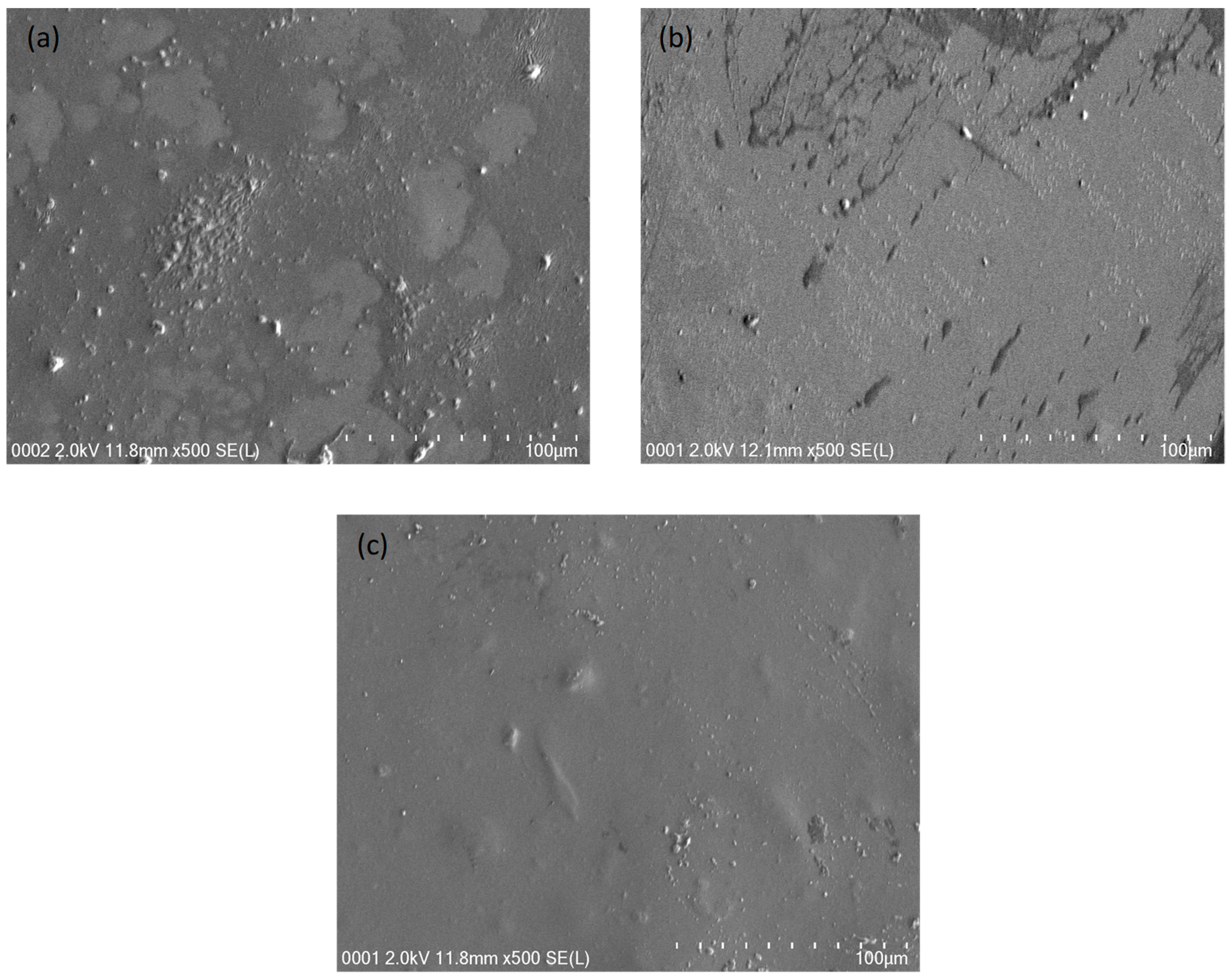
3.2. XRD and Morphology Analyses
3.3. Electrochemical Investigations
3.3.1. TNM Analysis
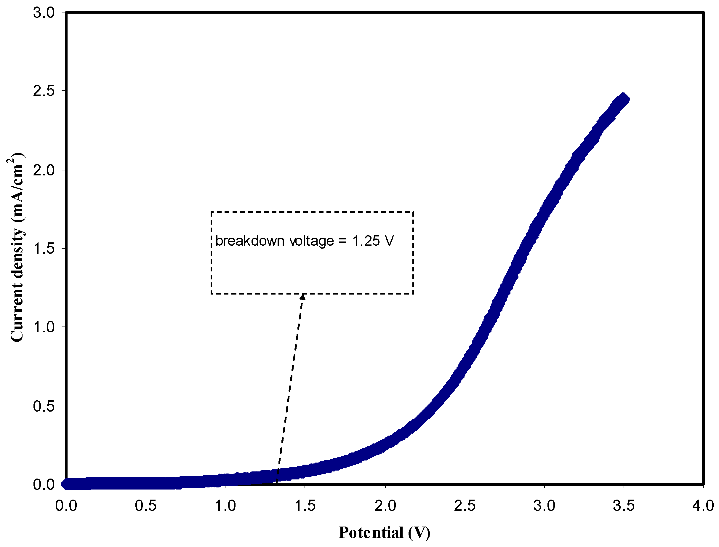
3.3.2. LSV Study
3.3.3. CV Analysis
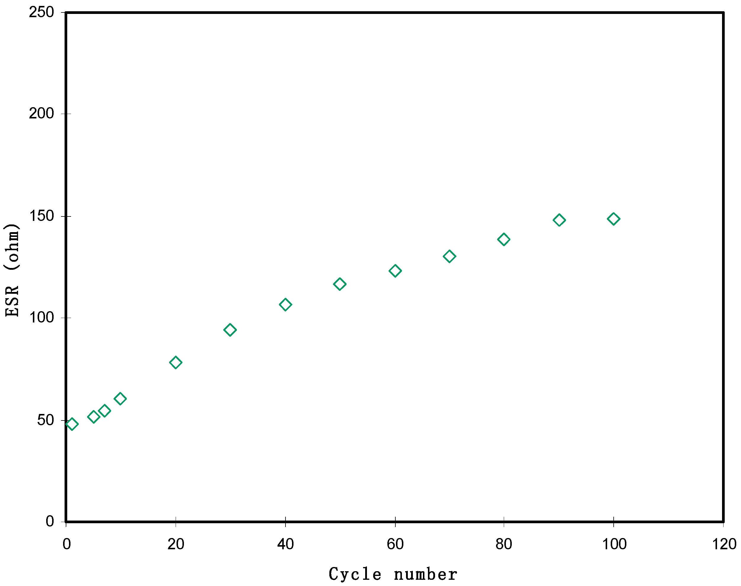
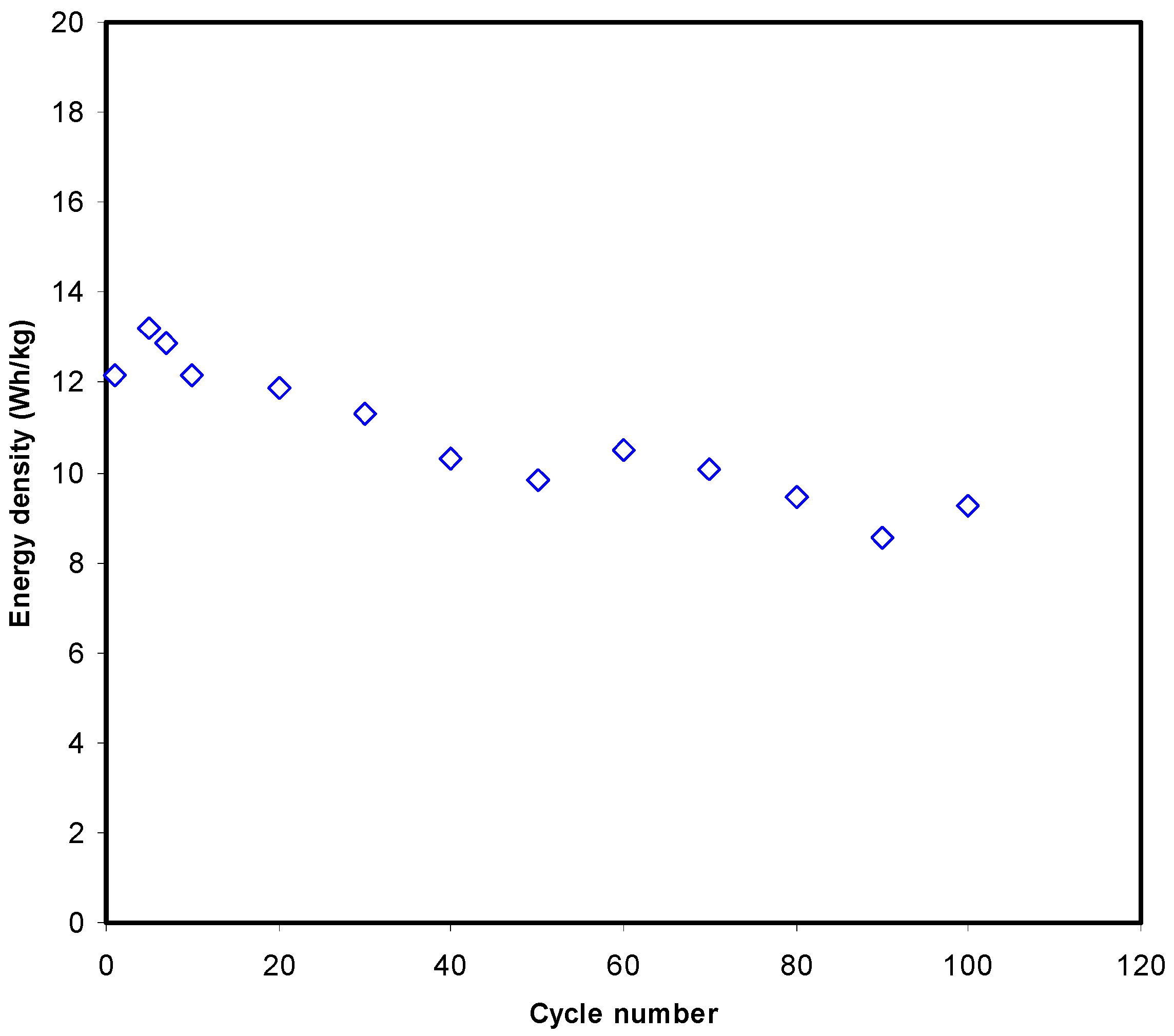
3.3.4. Galvanostatic Charge-Discharge (GCD) Analysis
4. Conclusion
Author Contributions
Funding
Institutional Review Board Statement
Informed Consent Statement
Data Availability Statement
Acknowledgments
Conflicts of Interest
References
- Brza, M.A.; Aziz, S.B.; Anuar, H.; Ali, F.; Hamsan, M.H.; Kadir, M.F.Z. Metal Framework as a Novel Approach for the Fabrication of Electric Double Layer Capacitor Device with High Energy Density Using Plasticized Poly(vinyl alcohol): Ammonium Thiocyanate Based Polymer Electrolyte. Arab. J. Chem. 2020, 13, 7247–7263. [Google Scholar] [CrossRef]
- Brza, M.A.B.; Aziz, S.; Anuar, H.; Dannoun, E.M.A.; Ali, F.; Abdulwahid, R.T.; Al-Zangana, S.; Kadir, M.F.Z. The Study of EDLC Device with High Electrochemical Performance Fabricated from Proton Ion Conducting PVA-Based Polymer Composite Electrolytes Plasticized with Glycerol. Polymers 2020, 12, 1896. [Google Scholar] [CrossRef] [PubMed]
- Sownthari, K.; Suthanthiraraj, S.A. Synthesis and characterization of an electrolyte system based on a biodegradable polymer. Express Polym. Lett. 2013, 7, 495–504. [Google Scholar] [CrossRef]
- Hadi, J.M.; Aziz, S.B.; Mustafa, M.S.; Brza, M.A.; Hamsan, M.H.; Kadir, M.F.Z.; Ghareeb, H.O.; Hussein, S.A. Electrochemical impedance study of proton conducting polymer electrolytes based on PVC doped with thiocyanate and plasticized with glycerol. Int. J. Electrochem. Sci. 2020, 15, 4671–4683. [Google Scholar] [CrossRef]
- Aziz, S.B.; Woo, T.J.; Kadir, M.F.Z.; Ahmed, H.M. A conceptual review on polymer electrolytes and ion transport models. J. Sci. Adv. Mater. Devices 2018, 3, 1–17. [Google Scholar] [CrossRef]
- Zhang, D.; Zhang, X.; Chen, Y.; Yu, P.; Wang, C.; Ma, Y. Enhanced capacitance and rate capability of graphene/polypyrrole composite as electrode material for supercapacitors. J. Power Sources 2011, 196, 5990–5996. [Google Scholar] [CrossRef]
- Ji, Y.; Liang, N.; Xu, J.; Qu, R.; Chen, D.; Zhang, H. Solid polymer electrolyte membranes based on quaternizedpolysulfone and solvent-free fluid as separators for electrical double-layer capacitors. Electrochim. Acta 2018, 283, 97–103. [Google Scholar] [CrossRef]
- Wang, X.; Wang, M.; Zhang, X.; Li, H.; Guo, X. Low-cost, green synthesis of highly porous carbons derived from lotus root shell as superior performance electrode materials in supercapacitor. J. Energy Chem. 2016, 25, 26–34. [Google Scholar] [CrossRef] [Green Version]
- Yu, S.; Yang, N.; Zhuang, H.; Meyer, J.; Mandal, S.; Williams, O.A.; Lilge, I.; Schönherr, H.; Jiang, X. Electrochemical Supercapacitors from Diamond. J. Phys. Chem. C 2015, 119, 18918–18926. [Google Scholar]
- Gao, Y.; Zhou, Y.S.; Qian, M.; He, X.N.; Redepenning, J.; Goodman, P.; Li, H.M.; Jiang, L.; Lu, Y.F. Chemical activation of carbon nano-onions for high-rate supercapacitor electrodes. Carbon N. Y. 2013, 51, 52–58. [Google Scholar] [CrossRef]
- Iro, Z.S.; Subramani, C.; Dash, S.S. A brief review on electrode materials for supercapacitor. Int. J. Electrochem. Sci. 2016, 11, 10628–10643. [Google Scholar] [CrossRef]
- Rasali, N.M.J.; Saadiah, M.A.; Zainuddin, N.K.; Nagao, Y.; Samsudin, A.S. Ionic transport studies of solid bio-polymer electrolytes based on carboxymethyl cellulose doped with ammonium acetate and its potential application as an electrical double layer capacitor. eXPRESS Polym. Lett. 2020, 14, 619–637. [Google Scholar] [CrossRef]
- Jothi, M.A.; Vanitha, D.; Nallamuthu, N.; Manikandan, A.; Bahadur, S.A. Investigations of lithium ion conducting polymer blend electrolytes using biodegradable cornstarch and PVP. Phys. B Condens. Matter 2020, 580, 411940. [Google Scholar] [CrossRef]
- Siddiqui, N.N.; Aman, A.; Silipo, A.; Qader, S.A.U.; Molinaro, A. Structural analysis and characterization of dextran produced by wild and mutant strains of Leuconostocmesenteroides. Carbohydr. Polym. 2014, 99, 331–338. [Google Scholar] [CrossRef]
- Chen, F.; Huang, G.; Huang, H. Preparation and application of dextran and its derivatives as carriers. Int. J. Boil. Macromol. 2020, 145, 827–834. [Google Scholar] [CrossRef] [PubMed]
- Sarwat, F.; Ahmed, N.; Aman, A.; Qader, S.A.U. Optimization of growth conditions for the isolation of dextran producing Leuconostoc spp. from indigenous food sources. Pak. J. Pharm. Sci. 2013, 26, 793–797. [Google Scholar]
- Barsbay, M.; Güner, A. Miscibility of dextran and poly(ethylene glycol) in solid state: Effect of the solvent choice. Carbohydr. Polym. 2007, 69, 214–223. [Google Scholar] [CrossRef]
- Arbia, W.; Arbia, L.; Adour, L.; Amrane, A. Chitin Extraction from Crustacean Shells Using Biological Methods—A Review. Food Technol. Biotechnol. 2013, 51, 12–25. [Google Scholar]
- Misenan, M.S.M.; Isa, M.I.N.; Khiar, A.S.A. Electrical and structural studies of polymer electrolyte based on chitosan/methyl cellulose blend doped with BMIMTFSI. Mater. Res. Express 2018, 5, 055304. [Google Scholar] [CrossRef]
- Asnawi, A.S.F.M.; Aziz, S.B.; Nofal, M.M.; Yusof, Y.M.; Brevik, I.; Hamsan, M.H.; Brza, M.A.; Abdulwahid, R.T.; Kadir, M.F.Z. Metal Complex as a Novel Approach to Enhance the Amorphous Phase and Improve the EDLC Performance of Plasticized Proton Conducting Chitosan-Based Polymer Electrolyte. Membranes 2020, 10, 132. [Google Scholar] [CrossRef]
- Brza, M.A.; Aziz, S.B.; Anuar, H.; Al Hazza, M.H.F. From Green Remediation to Polymer Hybrid Fabrication with Improved Optical Band Gaps. Int. J. Mol. Sci. 2019, 20, 3910. [Google Scholar] [CrossRef] [PubMed] [Green Version]
- Sudhakar, Y.N.; Selvakumar, M. Lithium perchlorate doped plasticized chitosan and starch blend as biodegradable polymer electrolyte for supercapacitors. Electrochim. Acta 2012, 78, 398–405. [Google Scholar] [CrossRef]
- Aziz, S.B.; Hadi, J.M.; Elham, E.M.; Abdulwahid, R.T.; Saeed, S.R.; Marf, A.S.; Karim, W.O.; Kadir, M.F.Z. The Study of Plasticized Amorphous Biopolymer Blend Electrolytes Based on Polyvinyl Alcohol (PVA): Chitosan with High Ion Conductivity for Energy Storage Electrical Double-Layer Capacitors (EDLC) Device Application. Polymers 2020, 12, 1938. [Google Scholar] [CrossRef] [PubMed]
- Bourtoom, T. Plasticizer effect on the properties of biodegradable blend from rice starch-chitosan. Songklanakarin J. Sci. Technol. 2008, 30, 149–155. [Google Scholar]
- Andrade, J.R.; Raphael, E.; Pawlicka, A. Plasticized pectin-based gel electrolytes. Electrochim. Acta 2009, 54, 6479–6483. [Google Scholar] [CrossRef]
- Peter, S.; Lyczko, N.; Gopakumar, D.; Maria, H.J.; Nzihou, A.; Thomas, S. Chitin and Chitosan Based Composites for Energy and Environmental Applications: A Review. Waste Biomass-Valorization 2020, 1–28. [Google Scholar] [CrossRef]
- Stepniak, I.; Galinski, M.; Nowacki, K.; Wysokowski, M.; Jakubowska, P.; Bazhenov, V.V.; Leisegang, T.; Ehrlich, H.; Jesionowski, T. A novel chitosan/sponge chitin origin material as a membrane for supercapacitors—preparation and characterization. RSC Adv. 2015, 6, 4007–4013. [Google Scholar] [CrossRef]
- Aziz, S.B.; Brza, M.A.; Hamsan, H.M.; Kadir, M.F.Z.; Abdulwahid, R.T. Electrochemical characteristics of solid state double-layer capacitor constructed from proton conducting chitosan-based polymer blend electrolytes. Polym. Bull. 2020, 2020, 1–19. [Google Scholar] [CrossRef]
- Aziz, S.B.; Brza, M.A.; Brevik, I.; Hamsan, M.H.; Abdulwahid, R.T.; Majid, S.R.; Kadir, M.F.Z.; Hussen, S.A.; Abdullah, R.M. Characteristics of Glycerolized Chitosan: NH4NO3-Based Polymer Electrolyte for Energy Storage Devices with Extremely High Specific Capacitance and Energy Density Over 1000 Cycles. Polymers 2020, 12, 2718. [Google Scholar] [CrossRef]
- Machappa, T.; Ambika Prasad, M.V.N. AC conductivity and dielectric behavior of polyaniline/sodium metavenadate (PANI/NaVO3) composites. Phys. B Condens. Matter 2009, 404, 4168–4172. [Google Scholar] [CrossRef]
- Hadi, J.M.; Aziz, S.B.; Saeed, S.R.; Brza, M.A.; Abdulwahid, R.T.; Hamsan, M.H.; Abdullah, R.M.; Kadir, M.F.Z.; Muzakir, S.K. Investigation of Ion Transport Parameters and Electrochemical Performance of Plasticized Biocompatible Chitosan-Based Proton Conducting Polymer Composite Electrolytes. Membranes 2020, 10, 363. [Google Scholar] [CrossRef] [PubMed]
- Nasef, M.M.; Saidi, H.; Dahlan, K.Z.M. Preparation of composite polymer electrolytes by electron beam-induced grafting: Proton- and lithium ion-conducting membranes. Nucl. Instrum. Methods Phys. Res. Sect. B Beam Interact. Mater. At. 2007, 265, 168–172. [Google Scholar] [CrossRef] [Green Version]
- Aziz, S.B.; Abidin, Z.; Arof, A. Effect of silver nanoparticles on the DC conductivity in chitosan–silver triflate polymer electrolyte. Phys. B Condens. Matter 2010, 405, 4429–4433. [Google Scholar] [CrossRef]
- Shukur, M.F.; Ithnin, R.; Kadir, M.F.Z. Electrical characterization of corn starch-LiOAc electrolytes and application in electrochemical double layer capacitor. Electrochim. Acta 2014, 136, 204–216. [Google Scholar] [CrossRef]
- Aziz, S.B.; Abdullah, R.M.; Kadir, M.F.Z.; Ahmed, H.M. Non suitability of silver ion conducting polymer electrolytes based on chitosan mediated by barium titanate (BaTiO3) for electrochemical device applications. Electrochim. Acta 2019, 296, 494–507. [Google Scholar] [CrossRef]
- Teo, L.P.; Buraidah, M.H.; Nor, A.F.M.; Majid, S.R. Conductivity and dielectric studies of Li2SnO3. Ionics 2012, 18, 655. [Google Scholar] [CrossRef]
- Aziz, S.B.; Abdullah, R.M. Crystalline and amorphous phase identification from the tanδ relaxation peaks and impedance plots in polymer blend electrolytes based on [CS:AgNt]x:PEO(x − 1) (10 ≤ x ≤ 50). ElectrochimicaActa 2018, 285, 30–46. [Google Scholar] [CrossRef]
- Aziz, S.B.; Abidin, Z.H.Z.; Arof, A.K. Influence of silver ion reduction on electrical modulus parameters of solid polymer electrolyte based on chitosan silver triflate electrolyte membrane. eXPRESS Polym. Lett. 2010, 4, 300–310. [Google Scholar] [CrossRef]
- Hema, M.; Selvasekerapandian, S.; Sakunthala, A.; Arunkumar, D.; Nithya, H. Structural, vibrational and electrical characterization of PVA–NH4Br polymer electrolyte system. Phys. B Condens. Matter 2008, 403, 2740–2747. [Google Scholar] [CrossRef]
- Mertens, I.J.A.; Wubbenhorst, M.; Oosterbaan, W.D.; Jenneskens, L.W.; van Turnhout, J. Novel Polymer Electrolytes Based on Amorphous Poly(etherester)s Containing 1,4,7-Trioxanonyl Main Chain Units. Ionic Conductivity versus Polymer Chain Mobility Macromolecules 1999, 32, 3314–3324. [Google Scholar]
- Aziz, B.; Hamsan, M.H.; Karim, W.O.; Marif, A.S.; Abdulwahid, R.T.; Kadir, M.F.Z.; Brza, M.A. Study of impedance and solid-state double-layer capacitor behavior of proton (H+)-conducting polymer blend electrolyte-based CS:PS polymers. Ionics 2020, 26, 4635–4649. [Google Scholar] [CrossRef]
- Aziz, S.B.; Hamsan, M.H.; Abdullah, R.M.; Abdulwahid, R.T.; Brza, M.A.; Marif, A.S.; Kadir, M.F.Z. Protonic EDLC cell based on chitosan (CS): Methylcellulose (MC) solid polymer blend electrolytes. Ionics 2020, 26, 1829–1840. [Google Scholar] [CrossRef]
- Aziz, S.B.; Brevik, I.; Hamsan, M.H.; Brza, M.A.; Nofal, M.M.; Abdullah, A.M.; Rostam, S.; Al-Zangana, S.; Muzakir, S.K.; Kadir, M.F.Z. Compatible Solid Polymer Electrolyte Based on Methyl Cellulose for Energy Storage Application: Structural, Electrical, and Electrochemical Properties. Polymers 2020, 12, 2257. [Google Scholar] [CrossRef]
- Göktepe, F.; Çelik, S.Ü.; Bozkurt, A. Preparation and the proton conductivity of chitosan/poly(vinyl phosphonic acid) complex polymer electrolytes. J. Non-Cryst. Solids 2008, 354, 3637–3642. [Google Scholar] [CrossRef]
- Dannoun, E.M.A.; Aziz, S.B.; Brza, M.A.; Nofal, M.M.; Asnawi, A.S.F.M.; Yusof, Y.M.; Al-Zangana, S.; Hamsan, M.H.; Kadir, M.F.Z.; Woo, H.J. The Study of Plasticized Solid Polymer Blend Electrolytes Based on Natural Polymers and Their Application for Energy Storage EDLC Devices. Polymers 2020, 12, 2531. [Google Scholar] [CrossRef]
- Aziz, S.B.; Abidin, Z.H.Z.; Kadir, M.F.Z. Innovative method to avoid the reduction of silver ions to silver nanoparticles (Ag+→Ag∘) in silver ion conducting based polymer electrolytes. Phys. Scr. 2015, 90, 35808. [Google Scholar] [CrossRef]
- Marf, A.S.; Aziz, S.B.; Abdullah, R.M. Plasticized H+ ion-conducting PVA:CS-based polymer blend electrolytes for energy storage EDLC application. J. Mater. Sci. Mater. Electron. 2020, 31, 18554–18568. [Google Scholar] [CrossRef]
- Wan, Y.; Creber, K.A.M.; Peppley, B.; Bui, V.T. Chitosan-based solid electrolyte composite membranes: I—Preparation and characterization. J. Membr. Sci. 2006, 280, 666–674. [Google Scholar] [CrossRef]
- Aziz, S.B. Role of Dielectric Constant on Ion Transport: Reformulated Arrhenius Equation. Adv. Mater. Sci. Eng. 2016, 2016, 11. [Google Scholar] [CrossRef] [Green Version]
- Aziz, S.B.; Hamsan, M.H.; Kadir, M.F.Z.; Karim, W.O.; Abdullah, R.M. Development of Polymer Blend Electrolyte Membranes Based on Chitosan: Dextran with High Ion Transport Properties for EDLC Application. Int. J. Mol. Sci. 2019, 20, 3369. [Google Scholar] [CrossRef] [Green Version]
- Hamsan, M.H.; Shukur, M.F.; Aziz, S.B.; Kadir, M.F.Z. Dextran from Leuconostocmesenteroides-doped ammonium salt-based green polymer electrolyte. Bull. Mater. Sci. 2019, 42, 57. [Google Scholar] [CrossRef] [Green Version]
- Aziz, S.B.; Rasheed, M.A.; Hussein, A.M.; Ahmed, H.M. Fabrication of polymer blend composites based on [PVA-PVP] (1 − x):(Ag 2 S) x (0.01 ≤ x ≤ 0.03) with small optical band gaps: Structural and optical properties. Mater. Sci. Semicond. Process. 2017, 71, 197–203. [Google Scholar] [CrossRef]
- Aziz, S.B.; Abidin, Z.H.Z. Ion-transport study in nanocomposite solid polymer electrolytes based on chitosan: Electrical and dielectric analysis. J. Appl. Polym. Sci. 2015, 132, 41774. [Google Scholar] [CrossRef]
- Hodge, R.M.; Edward, G.H.; Simon, G.P. Water absorption and states of water in semicrystalline poly(vinyl alcohol) films. Polymer 1996, 37, 1371–1376. [Google Scholar] [CrossRef]
- Brza, M.A.; Aziz, S.B.; Anuar, H.; Ali, F. Structural, ion transport parameter and electrochemical properties of plasticized polymer composite electrolyte based on PVA: A novel approach to fabricate high performance EDLC devices. Polym. Test. 2020, 91, 106813. [Google Scholar] [CrossRef]
- Mobarak, N.N.; Ahmad, A.; Abdullah, M.P.; Ramli, N.; Rahman, M.Y.A. Conductivity enhancement via chemical modification of chitosan based green polymer electrolyte. Electrochim. Acta 2013, 92, 161–167. [Google Scholar] [CrossRef]
- Rani, M.S.A.; Ahmad, A.; Mohamed, N.S. Influence of nano-sized fumed silica on physicochemical and electrochemical properties of cellulose derivatives-ionic liquid biopolymer electrolytes. Ionics 2018, 24, 807–814. [Google Scholar] [CrossRef]
- Syarifah, N.S.; Jusoh, M.A.; Yeow, Y.K.; Esa, F.; Sutjipto, A.G.E. Complex Permittivity Determination of Glycerol Using Graphical and Numerical Technique. Aust. J. Basic Appl. Sci. 2017, 11, 172–179. [Google Scholar]
- Sampathkumar, L.; Selvin, P.C.; Selvasekarapandian, S.; Perumal, P.; Chitra, R.; Muthukrishnan, M. Synthesis and characterization of biopolymer electrolyte based on tamarind seed polysaccharide, lithium perchlorate and ethylene carbonate for electrochemical applications. Ionics 2019, 25, 1067–1082. [Google Scholar] [CrossRef]
- Noor, N.A.M.; Isa, M.I.N. Investigation on transport and thermal studies of solid polymer electrolyte based on carboxymethyl cellulose doped ammonium thiocyanate for potential application in electrochemical devices. Int. J. Hydrog. Energy 2019, 44, 8298–8306. [Google Scholar] [CrossRef]
- Pandey, G.P.; Kumar, Y.; Hashmi, S.A. Ionic liquid incorporated PEO based polymer electrolyte for electrical double layer capacitors: A comparative study with lithium and magnesium systems. Solid State Ion. 2011, 190, 93–98. [Google Scholar] [CrossRef]
- Eftekhari, A. The mechanism of ultrafast supercapacitors. J. Mater. Chem.A 2018, 6, 2866–2876. [Google Scholar] [CrossRef]
- Deng, J.; Li, J.; Xiao, Z.; Song, S.; Li, L. Studies on Possible Ion-Confinement in Nanopore for Enhanced Supercapacitor Performance in 4V EMIBF4 Ionic Liquids. Nanomaterials 2019, 9, 1664. [Google Scholar] [CrossRef] [PubMed] [Green Version]
- Tripathi, M.; Tripathi, S.K. Electrical studies on ionic liquid-based gel polymer electrolyte for its application in EDLCs. Ionics 2017, 23, 2735–2746. [Google Scholar] [CrossRef]
- Boonen, L.; Kitzler, P.; Kasum, J. Processing of aqueous polymer electrolytes for supercapacitors via different industrial application methods. Prog. Org. Coat. 2018, 115, 107–114. [Google Scholar] [CrossRef]
- Łatoszynska, A.A.; Taberna, P.-L.; Simon, P.; Wieczorek, W. Proton conducting Gel Polymer Electrolytes for supercapacitor applications. Electrochim. Acta 2017, 242, 31–37. [Google Scholar] [CrossRef] [Green Version]
- Hina, M.; Bashir, S.; Kamran, K.; Ramesh, S.; Ramesh, K. Synthesis and characterization of self-healable poly (acrylamide) hydrogel electrolytes and their application in fabrication of aqueous supercapacitors. Polymer 2020, 210, 123020. [Google Scholar] [CrossRef]
- Mazuki, N.; Majeed, A.P.P.A.; Samsudin, A.S. Study on electrochemical properties of CMC-PVA doped NH4Br based solid polymer electrolytes system as application for EDLC. J. Polym. Res. 2020, 27, 135. [Google Scholar] [CrossRef]
- Zhong, C.; Deng, Y.; Hu, W.; Qiao, J.; Zhang, L.; Zhang, J. A review of electrolyte materials and compositions for electrochemical supercapacitors. Chem. Soc. Rev. 2015, 44, 7484–7539. [Google Scholar] [CrossRef]
- Muzaar, A.; Ahamed, M.B.; Deshmukh, K.; Thirumalai, J. A review on recent advances in hybrid supercapacitors: Design, fabrication and applications. Renew. Sustain. Energy Rev. 2019, 101, 123–145. [Google Scholar] [CrossRef]
- Hamsan, M.H.; Shukur, M.F.; Aziz, S.B.; Yusof, Y.M.; Kadir, M.F.Z. Influence of NH4Br as an ionic source on the structural/electrical properties of dextran-based biopolymer electrolytes and EDLC application. Bull. Mater. Sci. 2020, 43, 30. [Google Scholar] [CrossRef]
- Aziz, S.B.; Brza, M.A.; Hamsan, M.H.; Kadir, M.F.Z.; Muzakir, S.K.; Abdulwahid, R.T. Effect of ohmic-drop on electrochemical performance of EDLC fabricated from PVA:dextran:NH4I based polymer blend electrolytes. J. Mater. Res. Technol. 2020, 9, 3734–3745. [Google Scholar] [CrossRef]
- Shuhaimi, N.E.A.; Teo, L.P.; Woo, H.J.; Majid, S.R.; Arof, A.K. Electrical double-layer capacitors with plasticized polymer electrolyte based on methyl cellulose. Polym. Bull. 2012, 69, 807–826. [Google Scholar] [CrossRef]
- Aziz, S.B.; Brza, M.A.; Hamsan, D.M.H.; Hadi, J.M.; Kadir, M.F.Z.; Abdulwahid, R.T. The Study of Electrical and Electro-chemical Properties of Magnesium Ion Conducting CS: PVA Based Polymer Blend Electrolytes: Role of Lattice Energy of Magnesium Salts on EDLC Performance. Molecules 2020, 25, 4503. [Google Scholar] [CrossRef] [PubMed]
- Teoh, K.H.; Lim, C.S.; Liew, C.W.; Ramesh, S. Electric double-layer capacitors with corn starch-based biopolymer electrolytes incorporating silica as filler. Ionics 2015, 21, 2061–2068. [Google Scholar] [CrossRef]
- Lim, C.S.; Teoh, K.H.; Liew, C.W.; Ramesh, S. Capacitive behavior studies on electrical double layer capacitor using poly (vinyl alcohol)-lithium perchlorate based polymer electrolyte incorporated with TiO2. Mater. Chem. Phys. 2014, 143, 661–667. [Google Scholar] [CrossRef]


| GL (wt.%) | Sample Code |
|---|---|
| 12 | CSDN1 |
| 28 | CSDN2 |
| 42 | CSDN3 |
| Sample | n1 (rad) | n2 (rad) | K1 (F−1) | K2 (F−1) | C1 (F) | C2 (F) |
|---|---|---|---|---|---|---|
| CSDN1 | 0.773 | 0.604 | 1.0 × 10⁹ | 3.05 × 10⁵ | 1.0 × 10⁻⁹ | 3.28 × 10⁻⁶ |
| CSDN2 | - | 0.738 | - | 1.68 × 10⁵ | - | 5.95 × 10⁻⁶ |
| CSDN3 | - | 0.668 | - | 3.9 × 10⁴ | - | 2.56 × 10⁻⁵ |
| Code | Ionic Conductivity (σDC) (S·cm−1) |
|---|---|
| CSDN1 | 4.06 × 10⁻⁶ |
| CSDN2 | 6.43 × 10⁻⁵ |
| CSDN3 | 3.44 × 10⁻⁴ |
| Electrolyte | Degree of Crystallinity (%) |
|---|---|
| Pure CS | 15.97 |
| CSDN2 | 5.82 |
| CSDN3 | 1.69 |
| Electrolyte Composition | σDC (S cm−1) | Cs (F g−1) | E (Wh kg−1) | Ref. |
|---|---|---|---|---|
| Dextran:NH4Br | (1.67 ± 0.36) × 10−6 | 2.05 | - | [71] |
| PVA:Dextran:NH4I | 2.08 × 10⁻⁵ | 4.2 | 0.55 | [72] |
| MC-NH4NO3- PEG | 2.1 × 10⁻⁶ | 38 | 3.9 | [73] |
| CS-PVA-Mg(CF3SO3)2:GL | 1.016 × 10⁻⁵ | 32.69 | - | [74] |
| Corn starch: LiClO4: SiO2 | 1.23 × 10⁻⁴ | 9.83 | 0.9 | [75] |
| PVA:LiClO4:TiO2 | 1.3 × 10⁻⁴ | 12.5 | 1.56 | [76] |
| CS:DN:NH4I:Zn(II)-complex:GL | 3.44 × 10⁻⁴ | 108.3 | 12.2 | This work |
Publisher’s Note: MDPI stays neutral with regard to jurisdictional claims in published maps and institutional affiliations. |
© 2021 by the authors. Licensee MDPI, Basel, Switzerland. This article is an open access article distributed under the terms and conditions of the Creative Commons Attribution (CC BY) license (https://creativecommons.org/licenses/by/4.0/).
Share and Cite
Hamsan, M.H.; Nofal, M.M.; Aziz, S.B.; Brza, M.A.; Dannoun, E.M.A.; Murad, A.R.; Kadir, M.F.Z.; Muzakir, S.K. Plasticized Polymer Blend Electrolyte Based on Chitosan for Energy Storage Application: Structural, Circuit Modeling, Morphological and Electrochemical Properties. Polymers 2021, 13, 1233. https://0-doi-org.brum.beds.ac.uk/10.3390/polym13081233
Hamsan MH, Nofal MM, Aziz SB, Brza MA, Dannoun EMA, Murad AR, Kadir MFZ, Muzakir SK. Plasticized Polymer Blend Electrolyte Based on Chitosan for Energy Storage Application: Structural, Circuit Modeling, Morphological and Electrochemical Properties. Polymers. 2021; 13(8):1233. https://0-doi-org.brum.beds.ac.uk/10.3390/polym13081233
Chicago/Turabian StyleHamsan, M. H., Muaffaq M. Nofal, Shujahadeen B. Aziz, M. A. Brza, Elham M. A. Dannoun, Ary R. Murad, M. F. Z. Kadir, and S. K. Muzakir. 2021. "Plasticized Polymer Blend Electrolyte Based on Chitosan for Energy Storage Application: Structural, Circuit Modeling, Morphological and Electrochemical Properties" Polymers 13, no. 8: 1233. https://0-doi-org.brum.beds.ac.uk/10.3390/polym13081233