1. Introduction
Flat slab is a two-way load distributary system that directly rests on columns and its use has been found more recurrent in recent times [
1], mainly attributed to large flooring heights and the reduced construction times associated with it. The direct load transfer mechanism renders the supporting columns to act as upward concentrated loads. This effect is detrimental in the sense that it challenges the inherent shear capacity of the slab. The latter often comes second resulting in inclined cracks originating at the slab column’s intersecting surface. Nowadays, a significant number of flat slabs need to be strengthened [
2]. This demand may arise from several factors that include construction or design errors, disobeying code provisions, environmental deterioration of materials, or increase in gravitational load [
3]. Flat slabs are vulnerable to punching shear failure and many such circumstances have been reported [
4,
5,
6]. This insufficient shear capacity of concrete puts great demands on the use of additional shear reinforcement to counter punching shear failure and prevent the loss of structural integrity.
Several methods to strengthen inherently insufficient flat slabs include post-installation of shear reinforcement, enlarging the column periphery near the slab either by drop panel or column capitals [
7,
8,
9,
10]. Both the column capitals and drop panels result in a larger support area for flat slabs than that provided by bare columns. The bifold outcomes are the reductions both in shear stress and the required slab thickness. However, the aesthetics are compromised as it requires access to the upper slab face which is usually covered by the floor. Post-installation of shear reinforcement leaves undetected marks, slight appearance changes and can be practical in many cases in comparison to either drop panels or column capitals [
11]. Composite in nature, FRP was rated 8 to 10 times stronger in tension than common steel reinforcement [
12]. Brittle in behavior, it exhibits a unique tensile strength higher than steel with their weight equal to one-quarter of steel [
13]. Field applications have shown excellent performance and durability of FRP retrofitted structures [
14,
15,
16,
17,
18,
19,
20,
21,
22,
23,
24,
25]. FRP strips were bonded “On Grooves” (EBROG) and “In Grooves” (EBRIG). The strengthening pattern comprised of 1- or 2-layer FRP strips bonded under slabs on two grooves which were 4 or 8 mm wide and depth ranged from 8–12 mm. Results demonstrated that such FRP patterns were able to enhance punching shear strength up to 60% for EBROG while it grew up to 28% for EBR [
26].
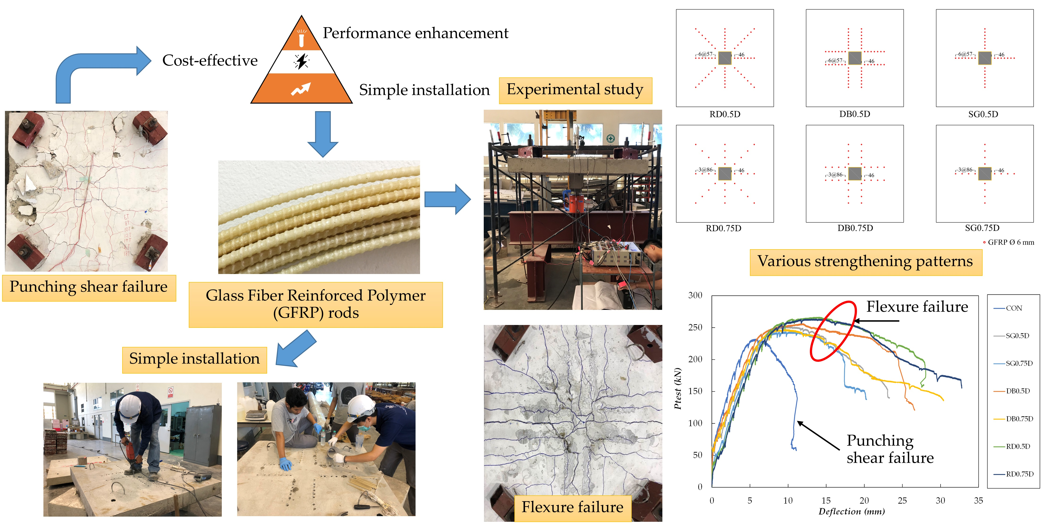
In the event when both the upper and lower slab surfaces are accessible, Glass Fiber Reinforced Polymer (GFRP) rods can be installed in holes pierced through slabs with the assistance of epoxy adhesives. The resulting system has shown promising results without compromising on the architecture of the system. In a similar manner, Carbon Fiber Reinforced Polymer (CFRP) fans can be installed through the holes drilled inside the slab and the resulting failure was effectively altered from shear to flexure [
27,
28,
29,
30]. GFRP is a common type of composite material whose fibers can be randomly arranged, flattened into a sheet, or woven into a fabric [
31,
32,
33]. Its ductility was found to be greater than CFRP [
34]. GFRP-reinforced two-way flat slabs indicated smaller post-cracking stiffness, larger crack widths, and smaller punching shear capacities than their equivalent steel reinforced slabs when identical reinforcement amounts were employed. This is ascribed to their smaller axial stiffness compared to steel bars [
35]. GFRP bars also possess the advantage of being cheaper than composite materials made up of carbon or aramid [
36,
37,
38].
Recently, GFRP was utilized in composite tube columns along with recycled aggregate concrete to furnish excellent compressive strength [
39]. Despite possessing brilliant inherent attributes, the use of GFRP as a shear reinforcement is very limited. GFRP was compared to steel reinforcement as shear reinforcement, and it was concluded to have comparable improvements in punching shear strength [
40]. Other studies also incorporated GFRP reinforcement as a replacement of steel reinforcement and concluded to have parallel enhancements in punching shear strength of flat slabs together with the alteration of failure mode from shear to flexure [
31,
32,
33,
34,
35,
36,
37,
38,
39,
40,
41,
42,
43]. Till now, GFRP bars have shown substantial potential as a suitable alternative to conventional steel shear reinforcement in flat slabs [
34,
35,
36,
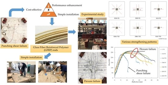
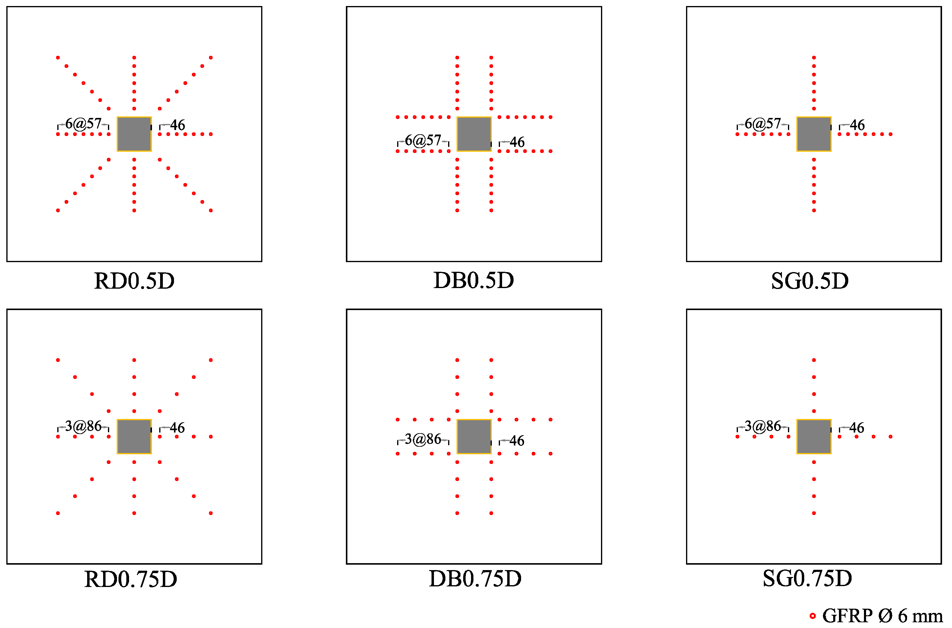
37]. However, its prospective in terms of post-installed shear enhancer is yet to be explored. The main objectives of this study are to explore the potential of GFRP as post-installed shear reinforcement, to investigate their installing patterns considering shear strength, ductility, and failure modes and to investigate the effect of shear critical section perimeter by varying the number of peripheral rings. It is to be noted that parameters such as the diameter of the GFRP rods and flat slab thickness are not varied in this study.
4. Analytical Validation
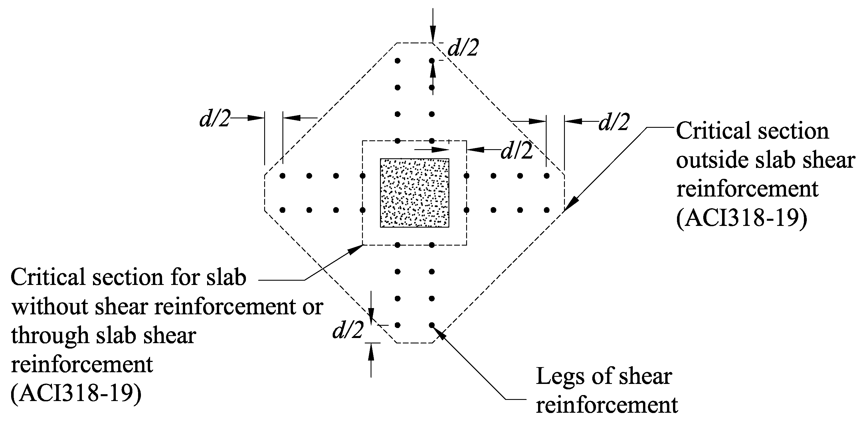
ACI 318-14 (2014) proposed the use of a critical shear section for two-way shear in slabs with shear reinforcement. This critical section is located at an offset of 0.5d from the column’s face. Another critical section at an offset of 0.5d beyond the outermost peripheral line of shear reinforcement should also be considered. For instance, critical sections to be considered in the DB0.75D shear strengthening pattern are shown in
Figure 12.
A shear-strengthened two-way slab can either fail within or outside the shear-strengthened zone depending upon the cumulative capacity of shear reinforcement and concrete.
4.1. Punching Shear Failure Inside the Shear-Strengthened Zone
ACI 318-14 proposes descriptive equations for shear capacity contributions from concrete
and shear reinforcement
as follows:
where:
= concrete cylinder compressive strength (MPa),
= effective slab thickness for shear (mm),
= perimeter of shear critical section at 0.5d from loading area periphery (mm),
= Factor according to the type of connection; it is 40 for internal columns, 30 for external columns, and 20 for corner columns,
= Ratio of the long side to the short side of the loading area periphery.
ACI 318-14 provides a descriptive equation for contribution in shear strength from steel studs as follows:
where:
= sum of the area of all shear reinforcement in one peripheral line,
= Yield strength of shear reinforcement,
= spacing between consecutive peripheral lines of shear reinforcement parallel to loading area periphery.
Total shear strength is a summation of the contributions from concrete and steel with an upper limit as:
Unlike steel, composite materials behave linearly in their stress–strain curves and do not possess any yield point. To incorporate the contribution of GFRP rods in total shear strength, Equation (2) is modified in this study. is replaced with while is replaced with
Where:
= sum of the area of GFRP reinforcement in one peripheral line,
= fracture strength of the GFRP,
Results concluded that only 50% of GFRP strength was utilized in this study. Hence, the strength contribution from GFRP is given as:
4.2. Punching Shear Failure Outside Shear-Strengthened Zone
ACI 318-14 (2014) proposes that the maximum shear strength is only provided by concrete (
) at a critical shear section offset from the outermost peripheral line of shear reinforcement equal to 0.5d. The corresponding equation is given as:
Table 5 and
Table 6 presents detailed calculations of analytical calculations of shear strength as per above-mentioned approach and the comparison with experimental values.
As demonstrated in
Table 6 (last column), a specimen with an SG pattern was unable to produce sufficient shear capacity to avoid punching shear failure within the shear-strengthened zone. On contrary, DB and RD patterns successfully shifted the punching shear failure outside their corresponding shear-strengthened zones. This is explained with their
ratios greater than 1.
5. Conclusions
This study aimed at strengthening flat slabs using post-installed GFRP rods. On this note, single, double, and radial at two spacings were investigated. The following conclusions may be drawn according to the results obtained from the experiments.
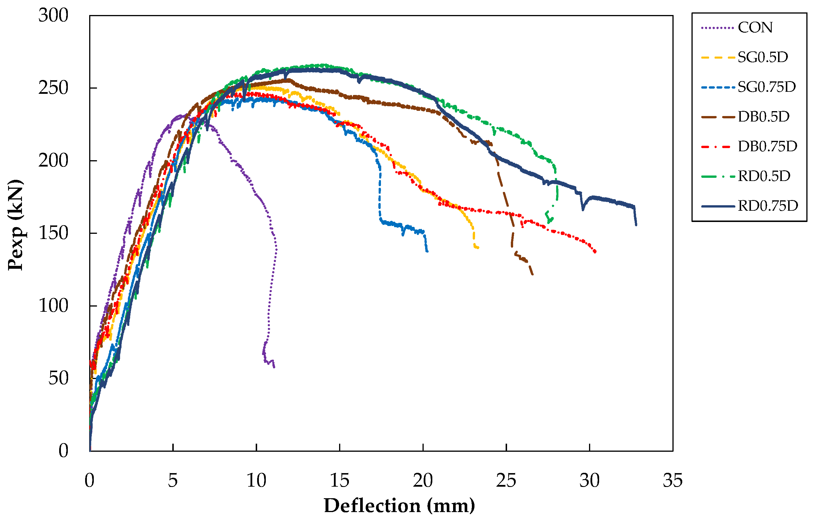
The load–deflection curve of the control specimen exhibited a sudden drop after attaining peak load. Strengthened specimens successfully shifted this failure mode to a gradual and ductile one. Improvements in both peak load and corresponding deflections were observed. Reducing the spacing from 0.75D to 0.5D had a beneficial impact on peak load for each GFRP pattern.
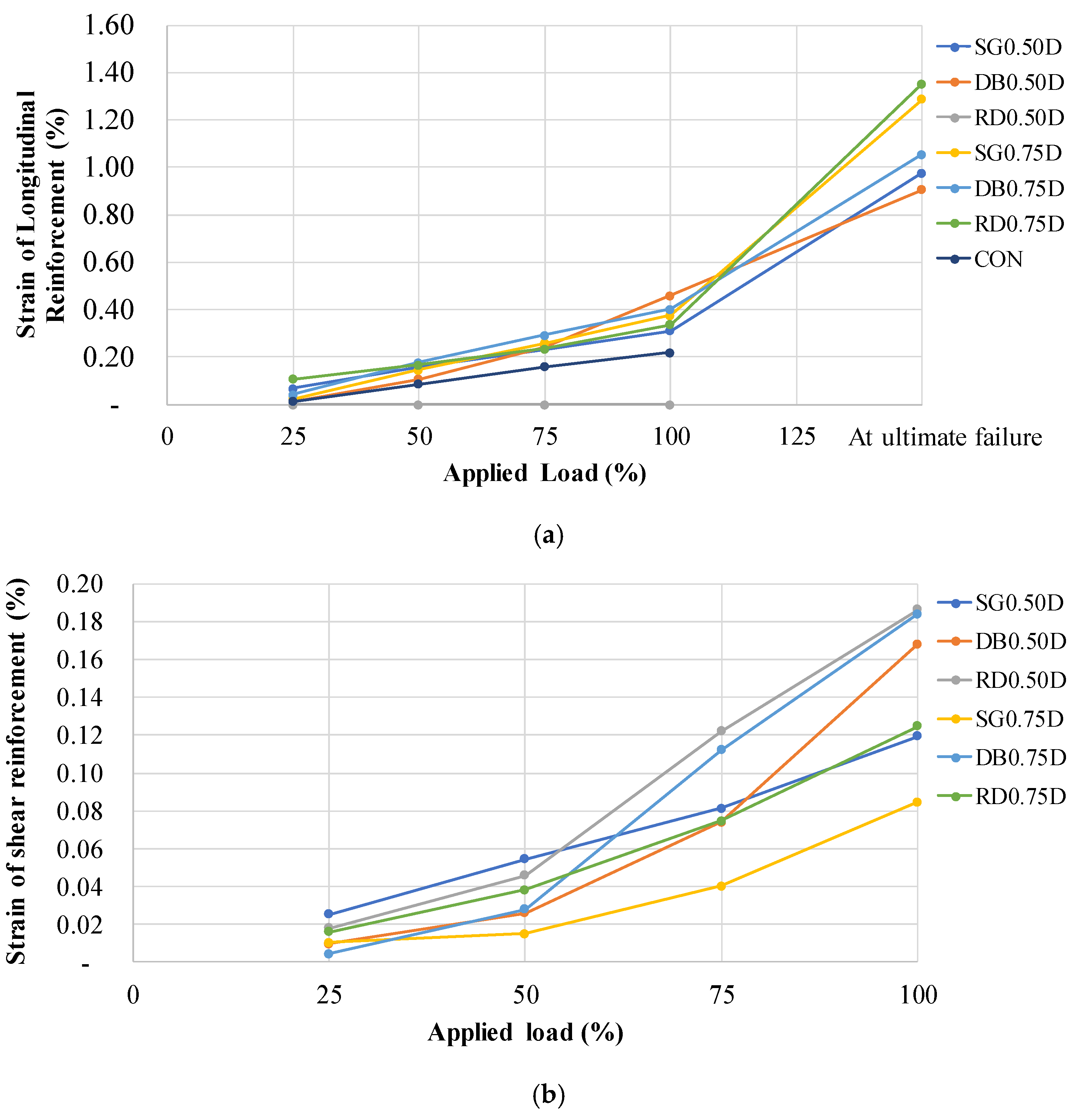
Strain measurement indicated no yielding of longitudinal bars in the control specimen. On the contrary, all strengthened specimens exhibited yielding. The highest strain values at peak loads were mobilized in double GFRP patterns followed by single and radial patterns, respectively. In terms of shear strain, the lowest shear strains were mobilized in SG patterns in both series. Specimen RD0.5D mobilized higher strain values than specimen DB0.5D. However, the opposite was true in series 0.75D. This implies that at reduced spacings, the radial pattern outperformed other patterns in terms of peak loads and ductility as the GFRP rods were able to withstand higher strain values.
As expected, the control specimen did not show any ductility. Nevertheless, strengthening with GFRP rods developed ductility. Reducing the GFRP spacing resulted in an increase in ductility irrespective of the type of GFRP pattern.
In each series, the SG pattern formed the lowest bound of dissipated energy. Results indicate that reducing the spacings had a beneficial effect on energy dissipation for the SG pattern. Maximum energy was dissipated by specimen RD0.75D and contrary to SG specimens, reducing the spacing to 0.5D resulted in a 12.25% reduction of energy dissipation capacity. Analogous to this, the DB pattern also exhibited a 1.26% reduction in energy dissipation capacity as GFRP spacings reduced from 0.75D to 0.5D.
It can be concluded that the use of GFRP rods is beneficial in the remediation of punching shear failure and GFRP rods can be effectively used in existing structures to improve the structural response of flat slabs.
ACI 318-14 equations for two-way shear strength were modified to incorporate shear strength contributions from the GFRP. A comparison of analytical results with experimental results suggests that the proposed approach is successful in predicting the shear strength capacity of flat slabs in the presence of GFRP rods.
Based on experimental results, GFRP bars can be effectively utilized in enhancing the shear strength of flat slabs. Mode of failure becomes ductile with increased peak loads, ductility and energy dissipation capacities as compared to control specimens. Of the three GFRP patterns studied, the radial pattern provided maximum improvements in terms of peak loads and energy dissipation capacities. This is the only pattern that was least affected by GFRP rods’ spacing.


 ,
, 


