
Recent Achievements on Grating Fabrications in Polymer Optical Fibers with Photosensitive Dopants: A Review


Abstract
:1. Introduction
2. Photosensitive Dopants in POFs
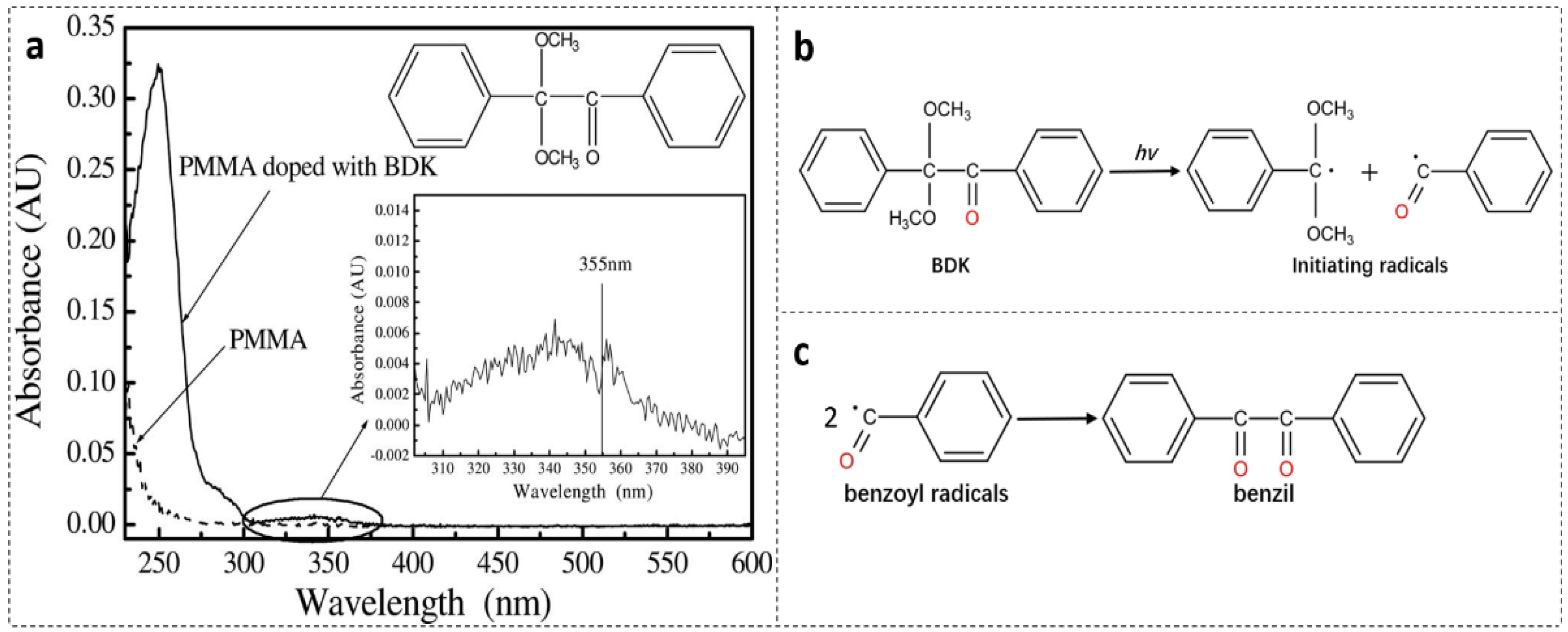
2.1. BDK
2.2. TS
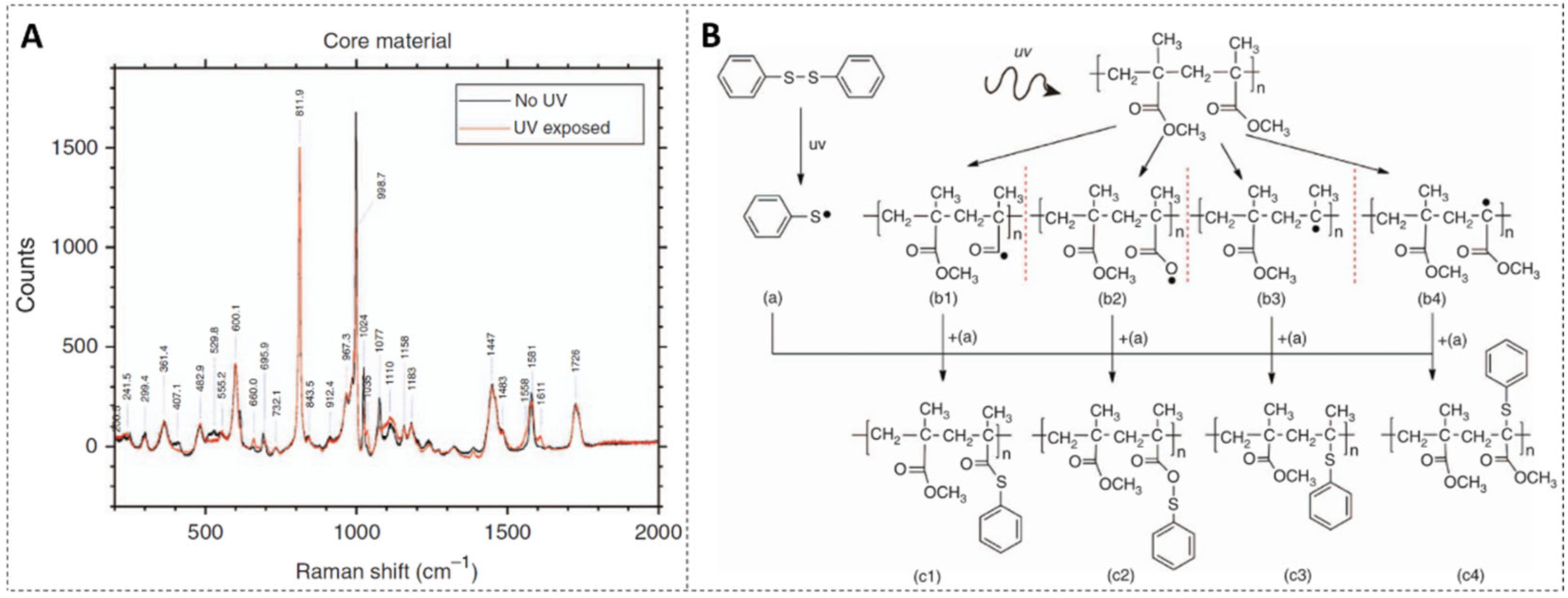
2.3. DPDS
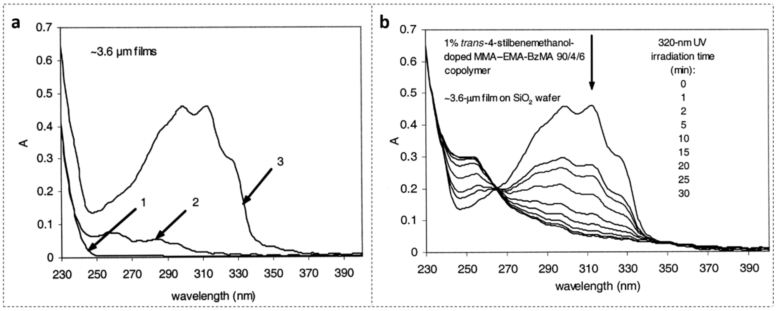
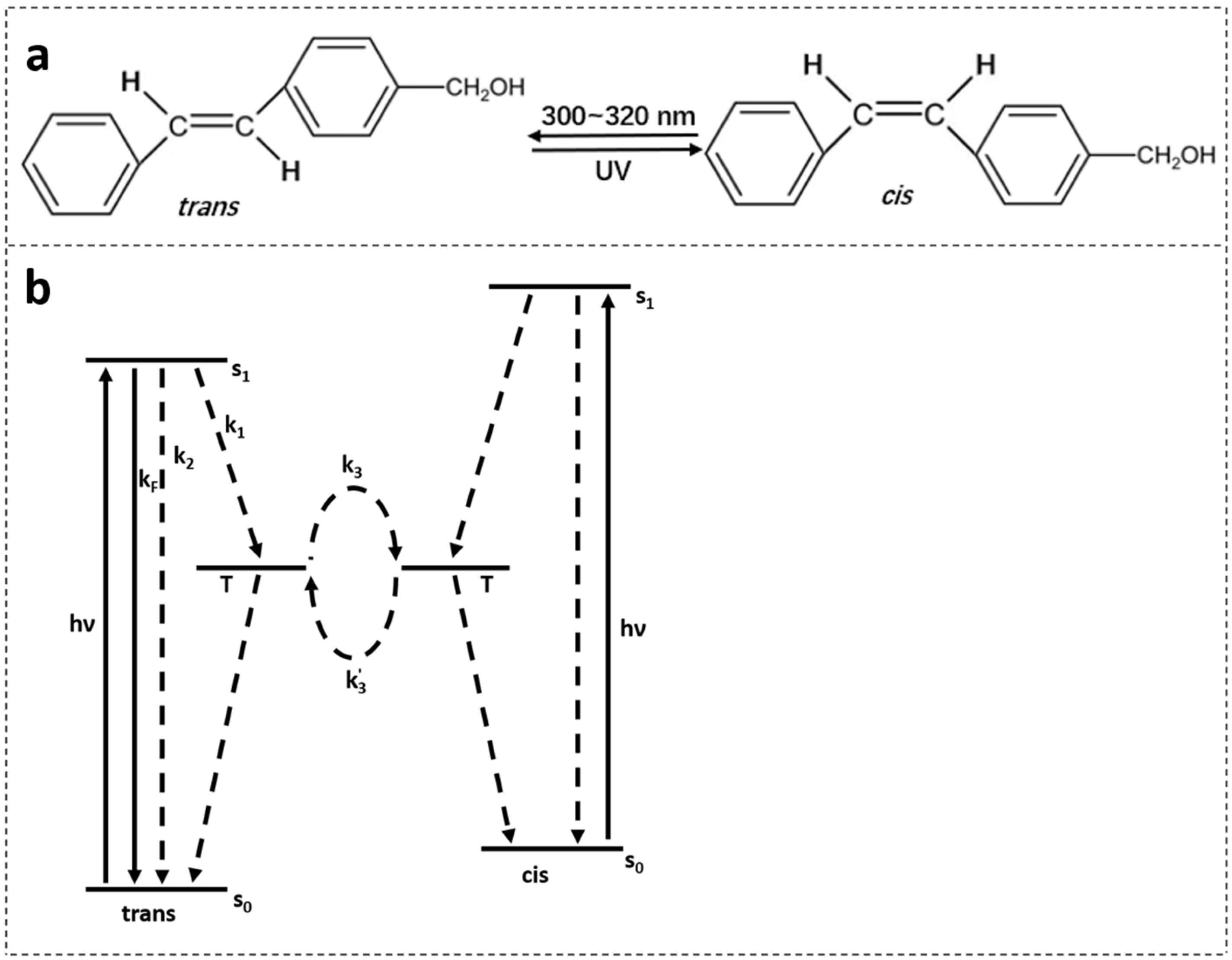
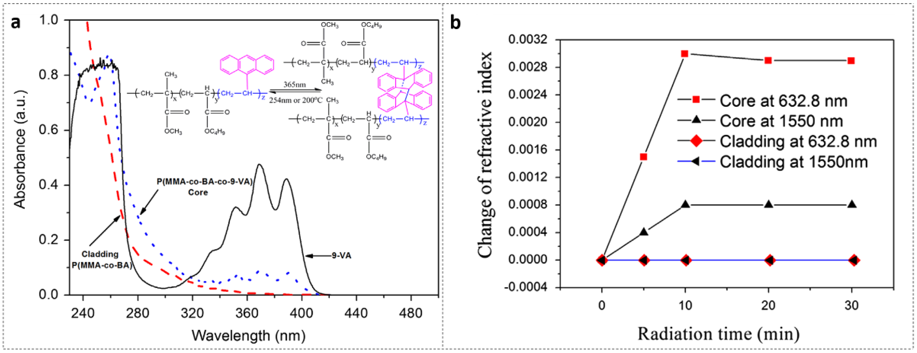
2.4. 9-VA
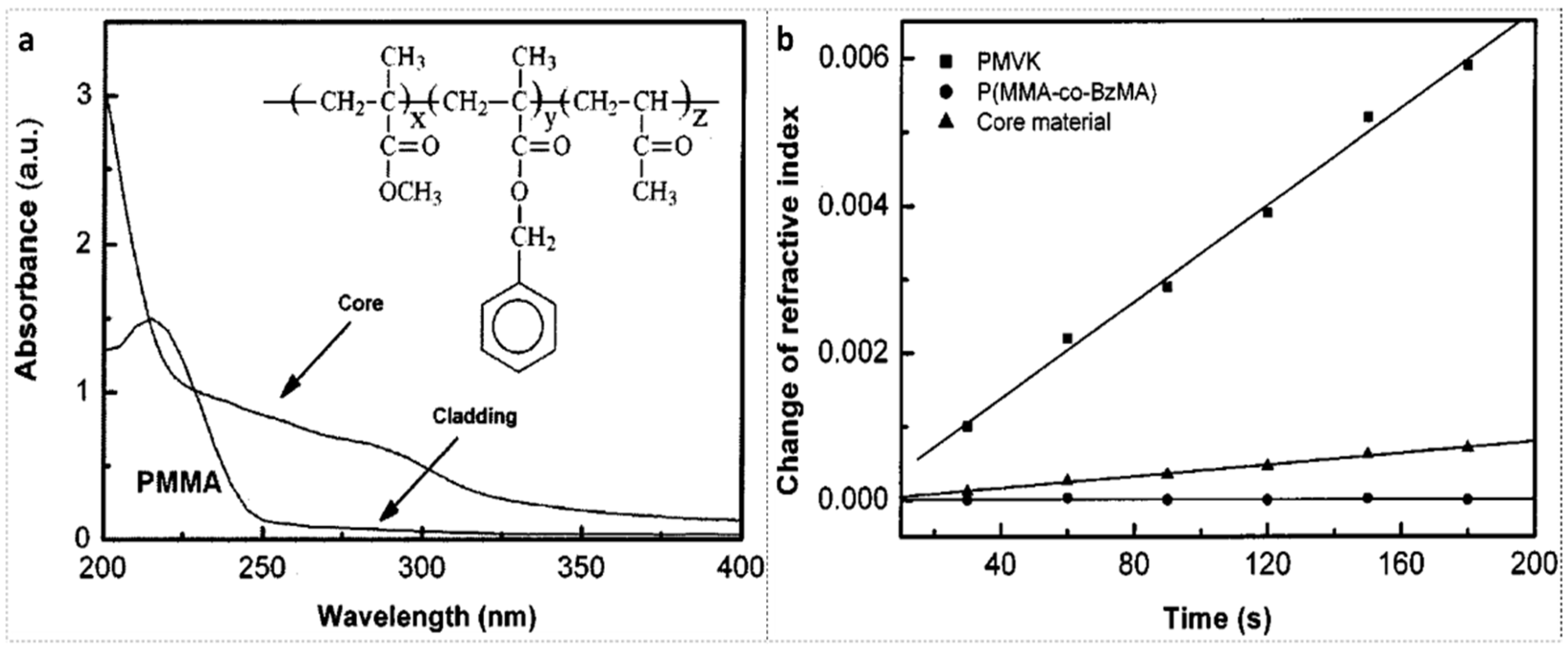
2.5. MVK
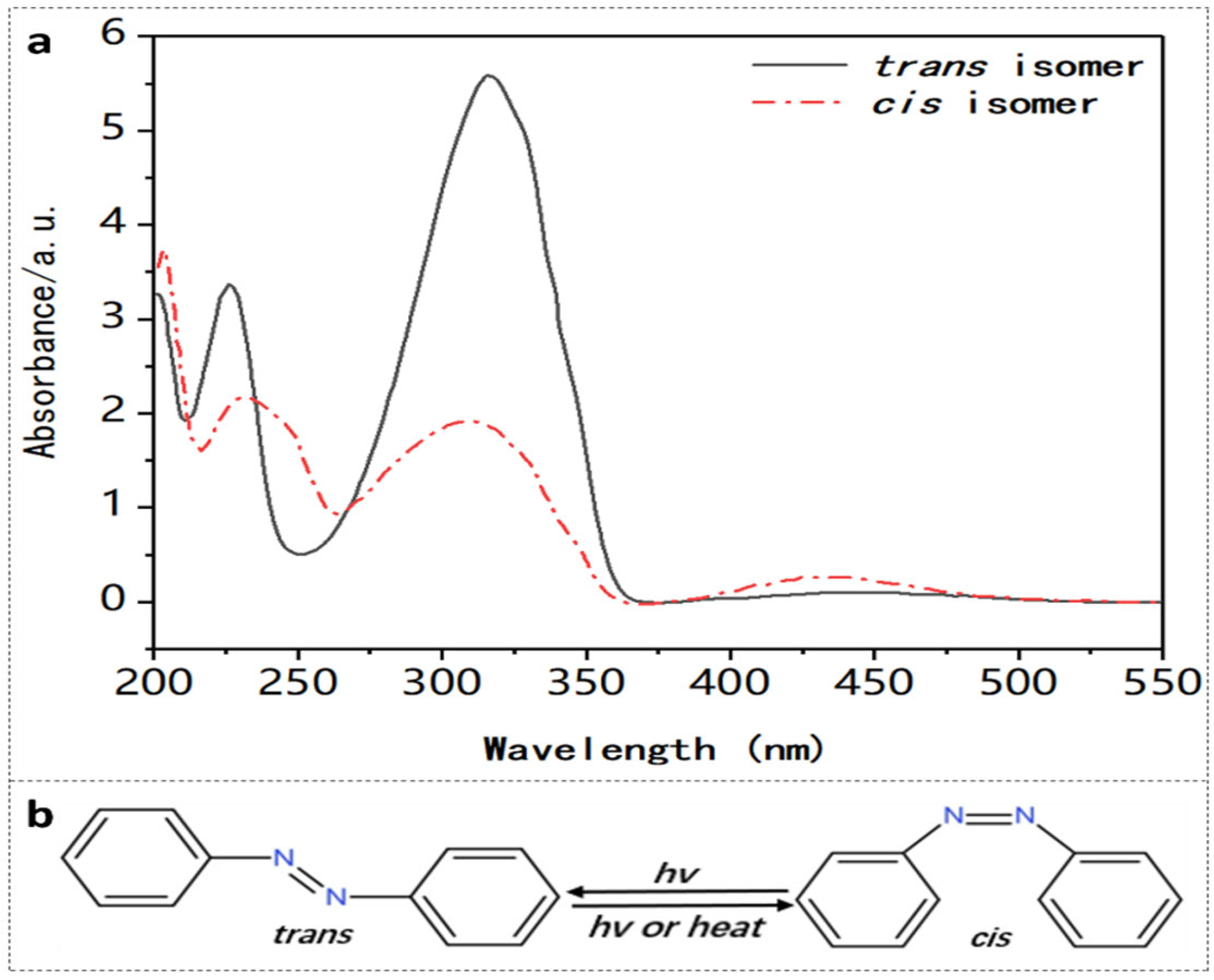
2.6. AZO
3. Photosensitive POF Fabrication Technique
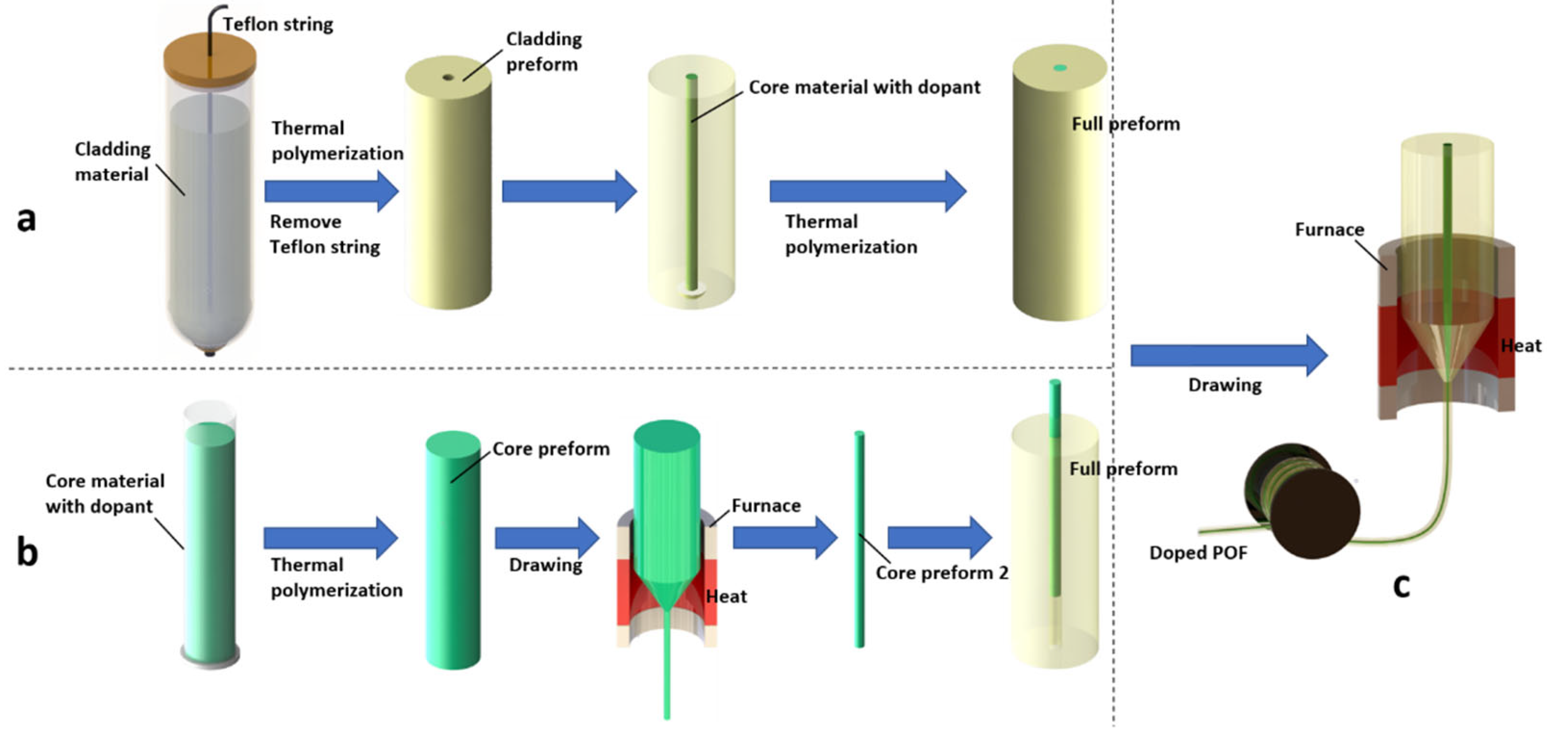
3.1. Double-Polymerization Technique
3.2. Pull-Through Technique
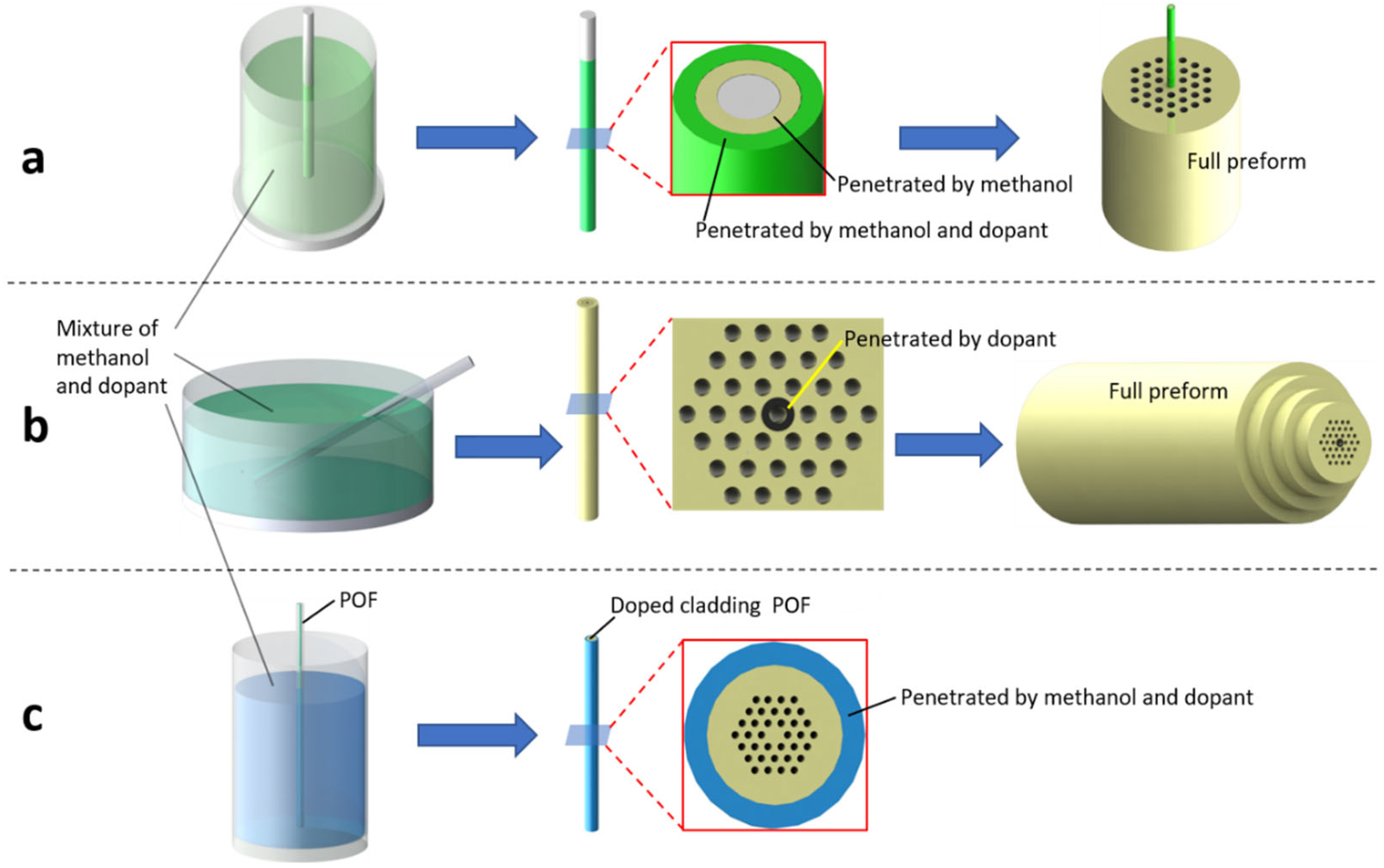
3.3. Diffusion Doping Technique
3.4. Doping Technique Comparison
4. Types of POF Gratings
4.1. Short Period Gratings
4.1.1. Standard FBGs
4.1.2. TFBGs
4.1.3. PSFBGs
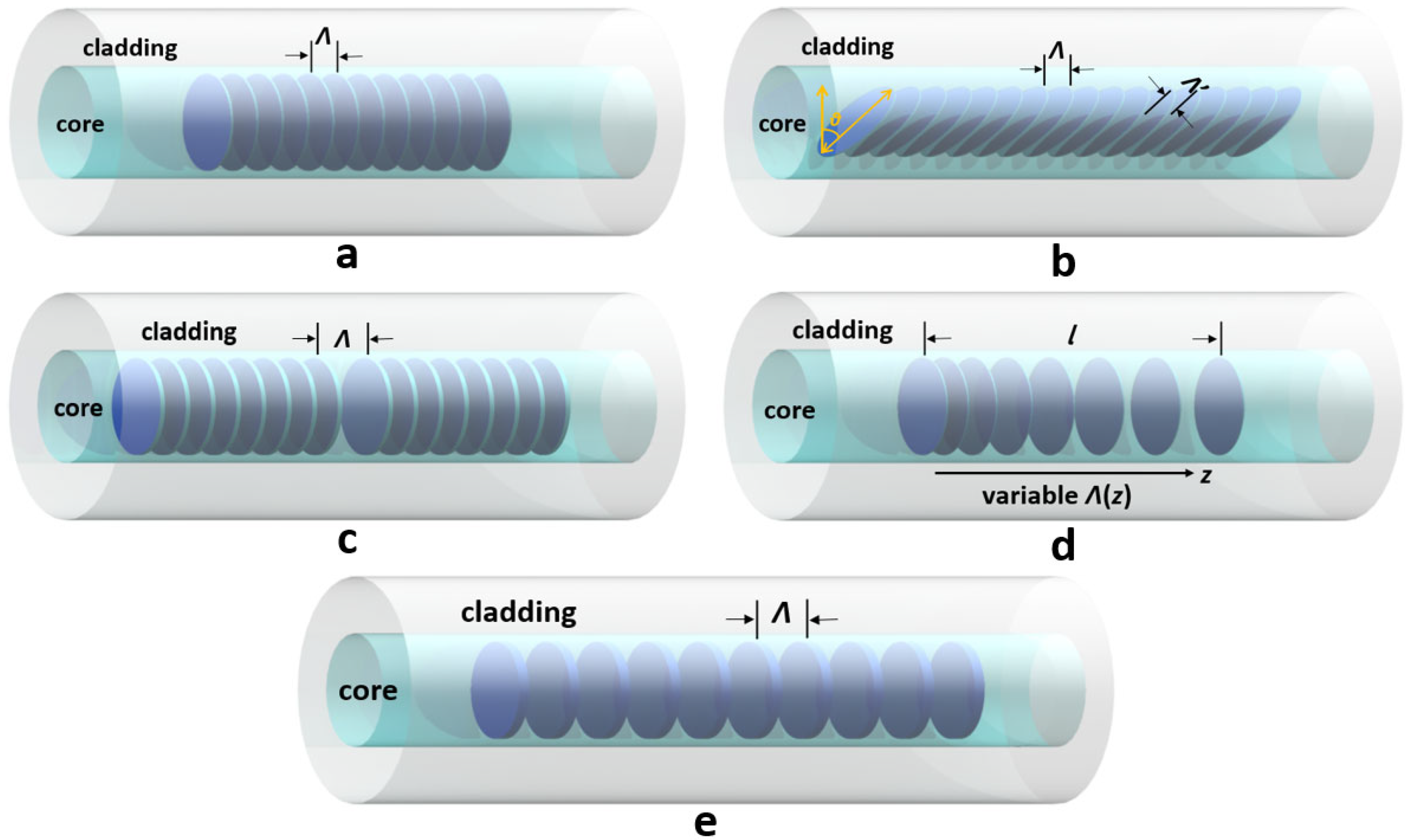
4.1.4. CFBGs
4.2. LPFGs
5. Grating Inscriptions in Doped PMMA POFs
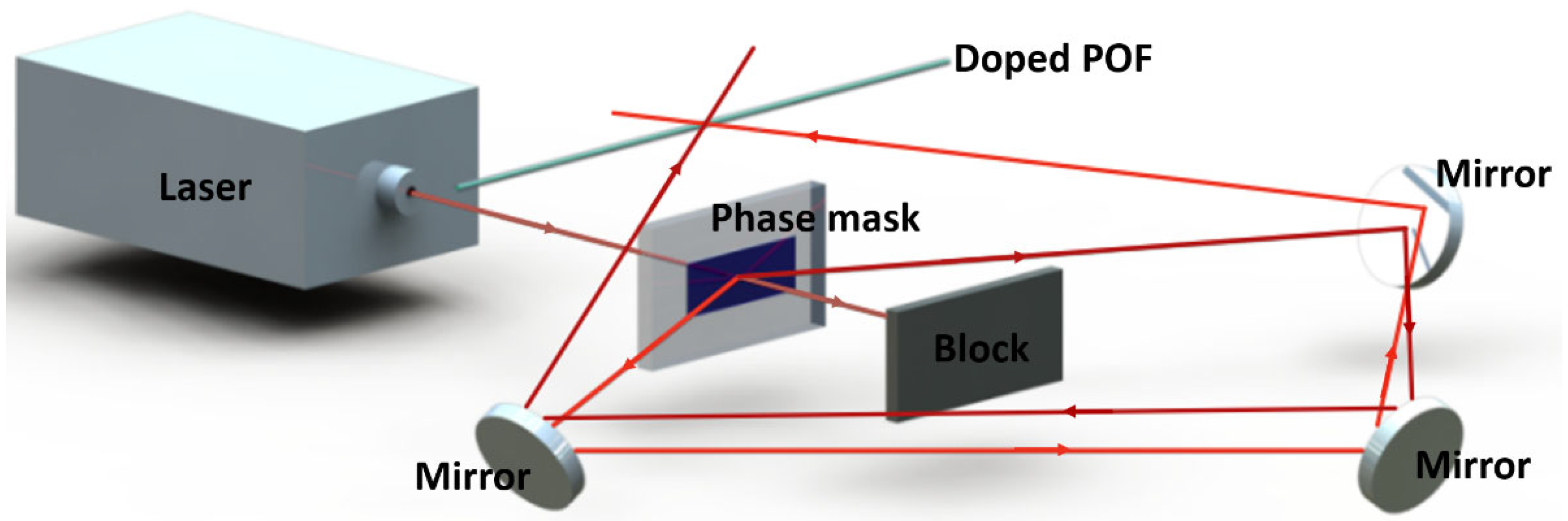
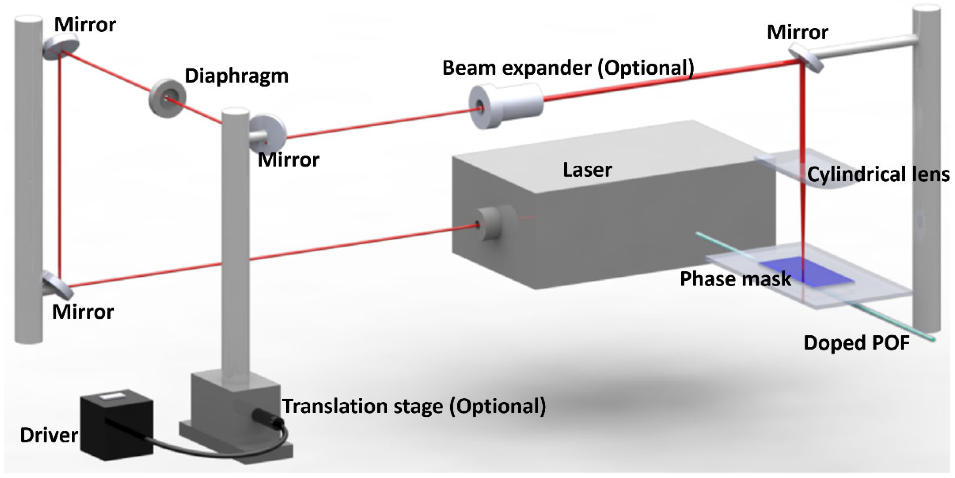
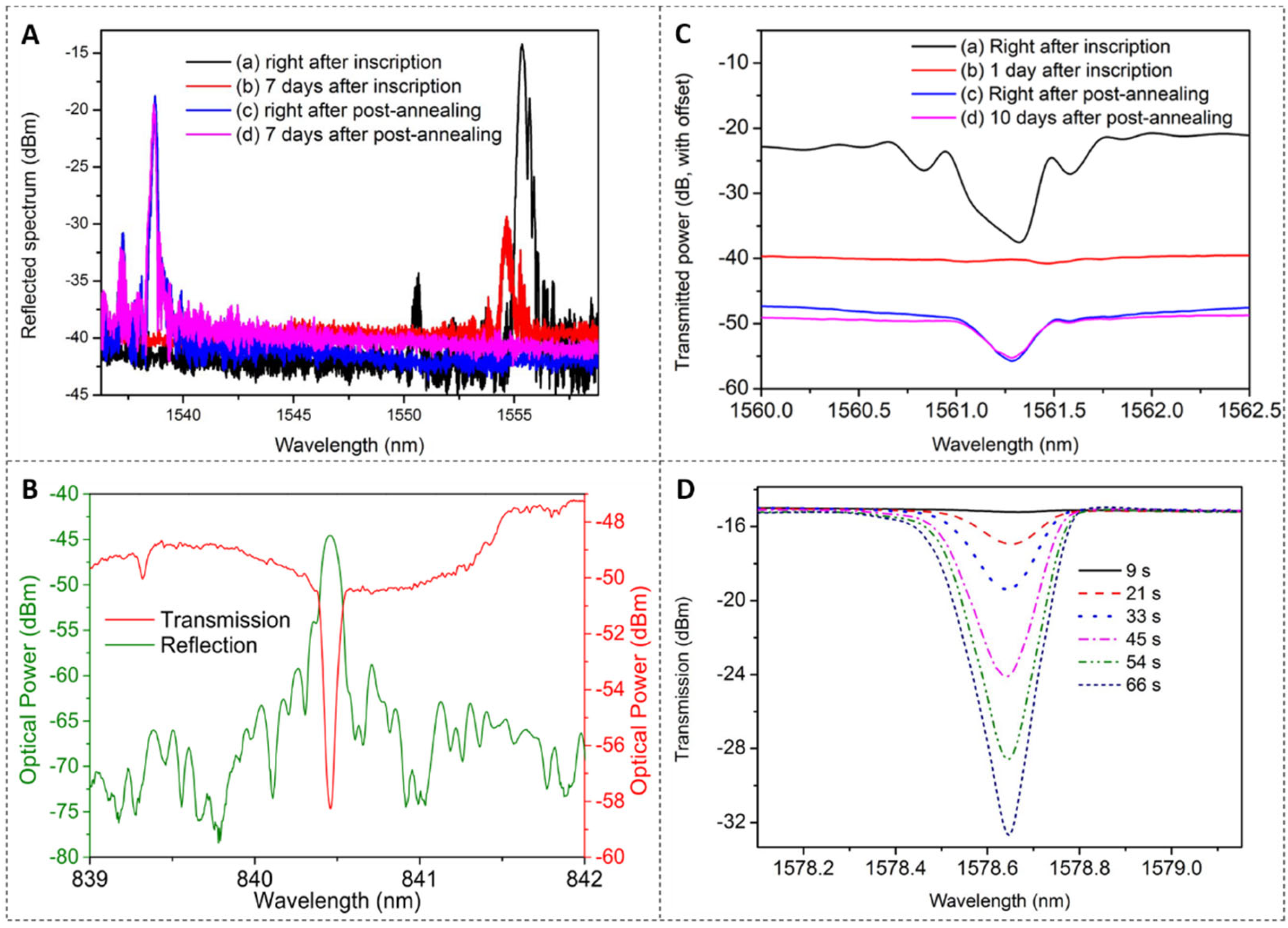
5.1. FBGs in POFs
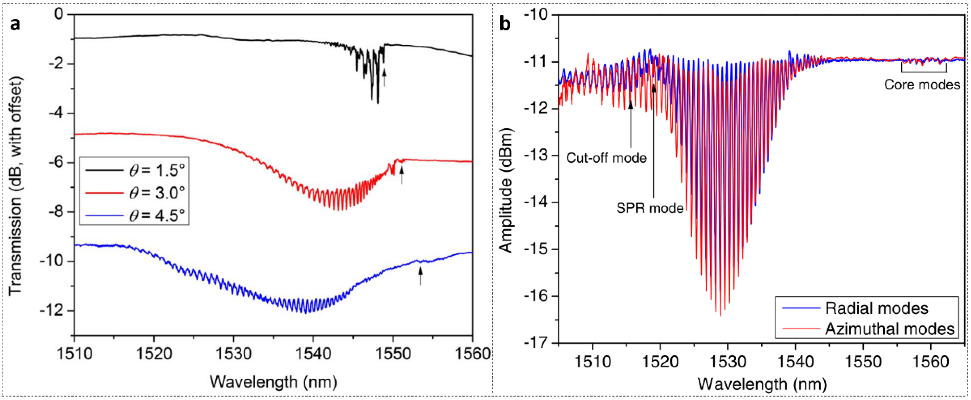
5.2. TFBGs in POFs
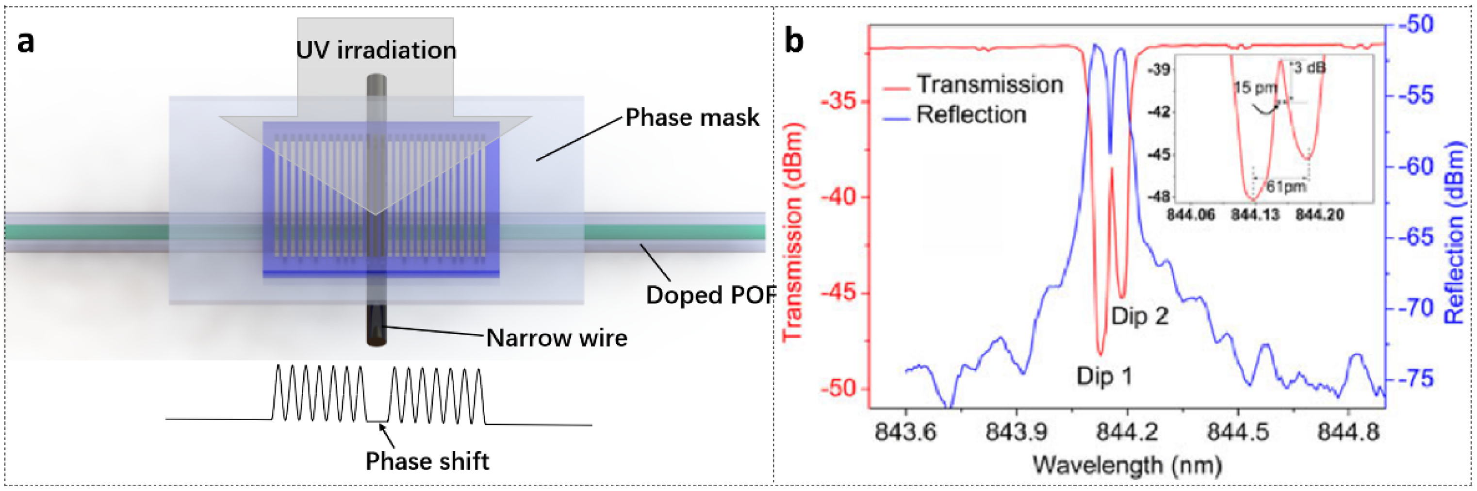
5.3. PSFBGs in POFs
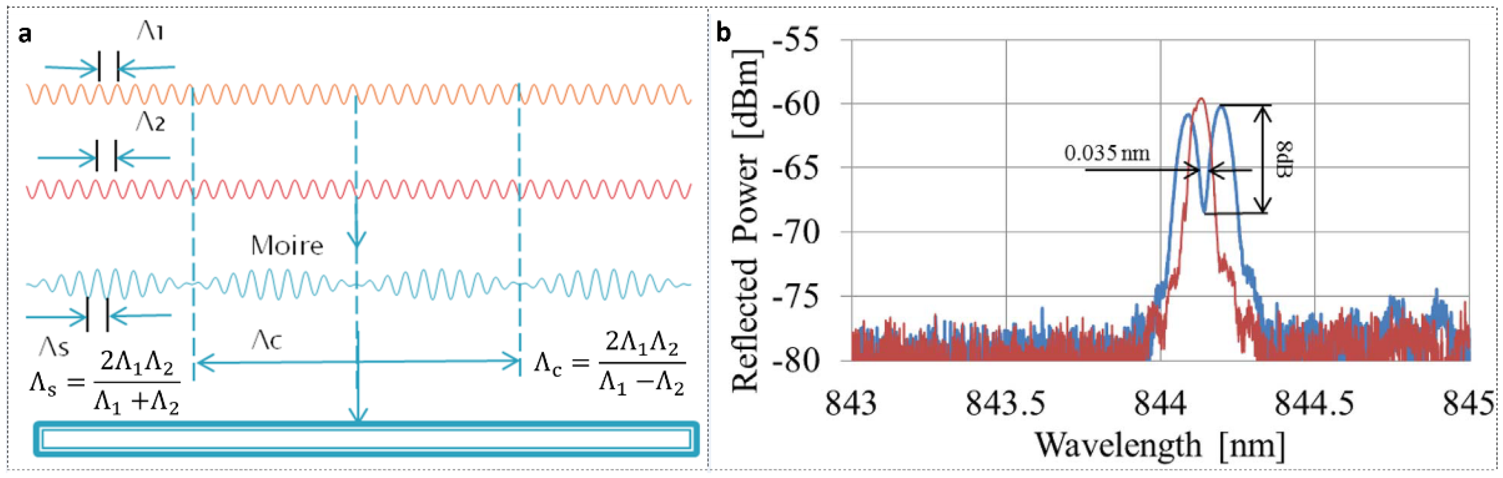
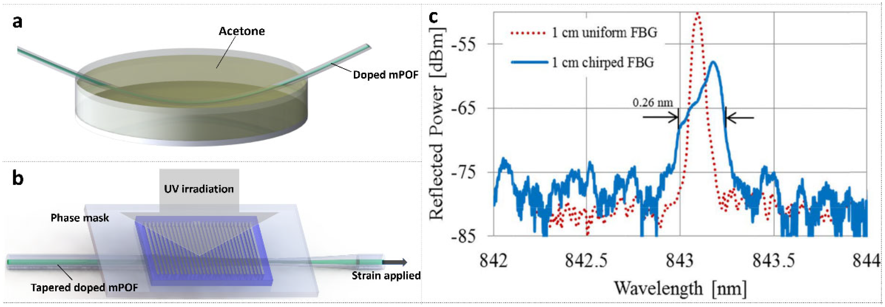
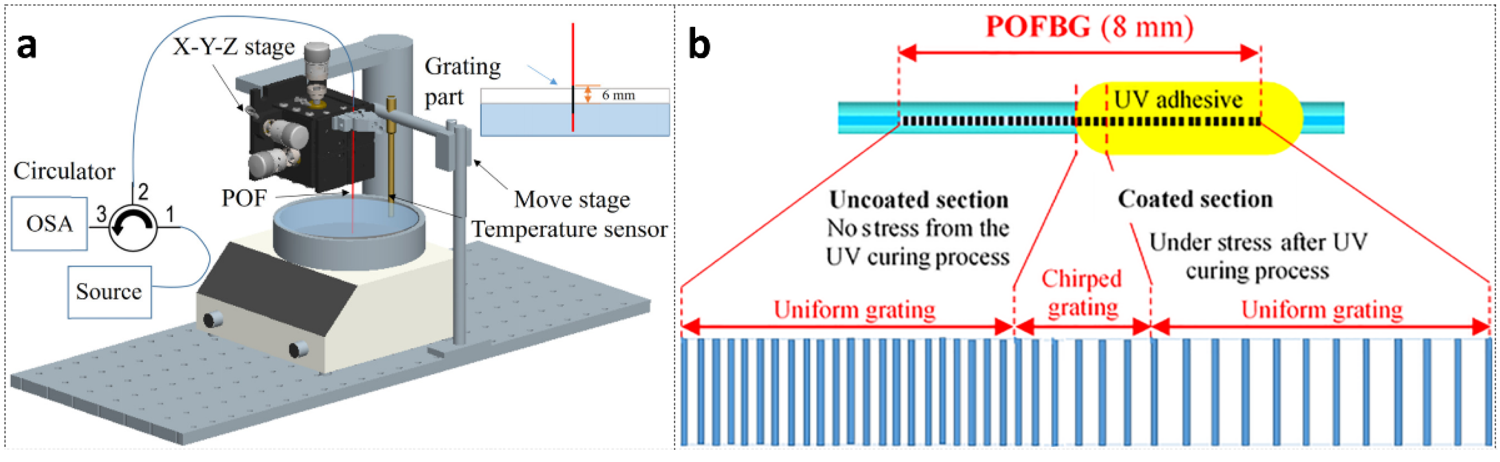
5.4. CFBGs in POFs
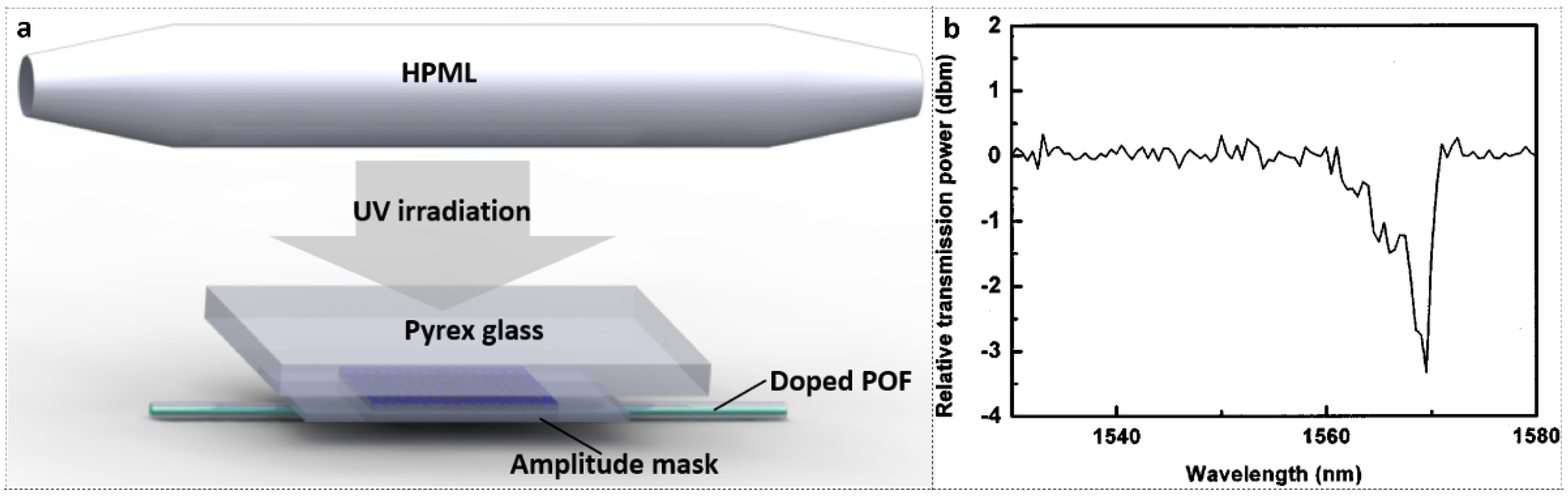
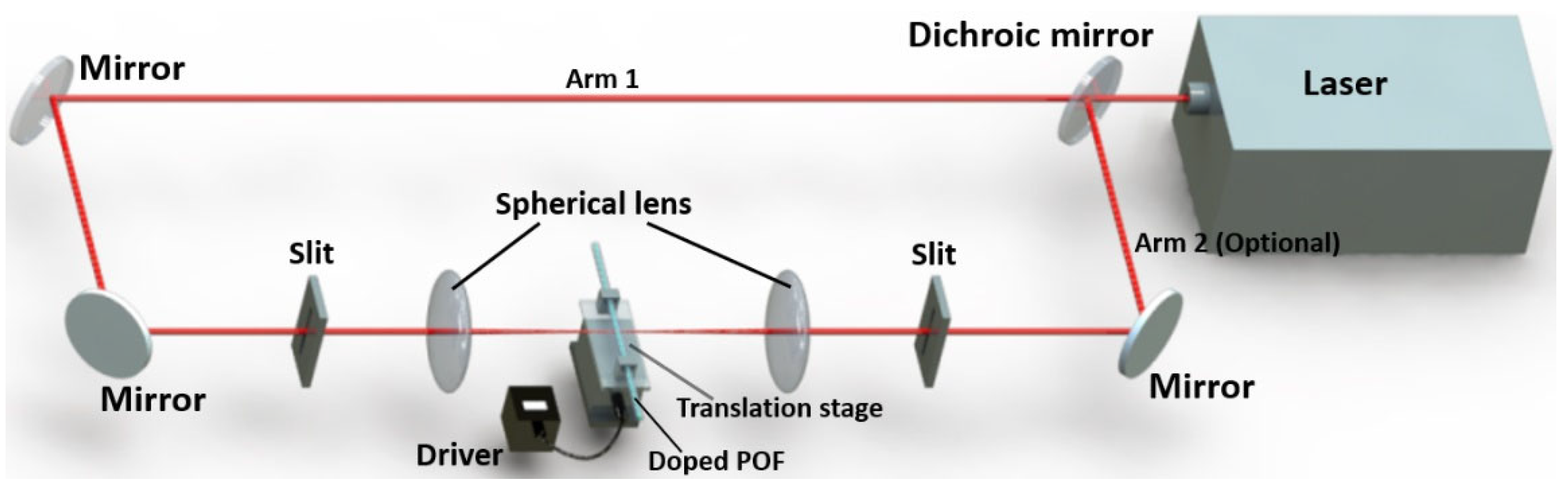
5.5. LPFGs in POFs
6. Conclusions
Author Contributions
Funding
Institutional Review Board Statement
Informed Consent Statement
Conflicts of Interest
References
- Ziemann, O.; Krauser, J.; Zamzow, P.E.; Daum, W. POF Handbook; Springer: Heidelberg, Germany, 2008. [Google Scholar]
- Broadway, C.; Min, R.; Leal-Junior, A.G.; Marques, C.; Caucheteur, C. Toward Commercial Polymer Fiber Bragg Grating Sensors: Review and Applications. J. Lightwave Technol. 2019, 37, 2605–2615. [Google Scholar] [CrossRef]
- Peters, K. Polymer optical fiber sensors—A review. Smart Mater. Struct. 2010, 20, 013002. [Google Scholar] [CrossRef]
- Bonefacino, J.; Tam, H.-Y.; Glen, T.S.; Cheng, X.; Pun, C.-F.J.; Wang, J.; Lee, P.-H.; Tse, M.-L.V.; Boles, S.T. Ultra-fast polymer optical fibre Bragg grating inscription for medical devices. Light: Sci. Appl. 2018, 7, 17161. [Google Scholar] [CrossRef] [PubMed]
- Min, R.; Hu, X.; Pereira, L.; Soares, M.S.; Silva, L.C.; Wang, G.; Martins, L.; Qu, H.; Antunes, P.; Marques, C. Polymer optical fiber for monitoring human physiological and body function: A comprehensive review on mechanisms, materials, and applications. Opt. Laser Technol. 2022, 147, 107626. [Google Scholar] [CrossRef]
- Jessy, R.S.; Ibrahim, M.H. Biodegradability and Biocompatibility of Polymers with Emphasis on Bone Scaffolding: A Brief Review. Int. J. Sci. Res. Publ. 2014, 4, 7–9. [Google Scholar]
- Wang, Y.; Huang, Y.; Bai, H.; Wang, G.; Hu, X.; Kumar, S.; Min, R. Biocompatible and Biodegradable Polymer Optical Fiber for Biomedical Application: A Review. Biosensors 2021, 11, 472. [Google Scholar] [CrossRef] [PubMed]
- Xiong, Z.; Peng, G.; Wu, B.; Chu, P. Highly tunable Bragg gratings in single-mode polymer optical fibers. IEEE Photonics Technol. Lett. 1999, 11, 352–354. [Google Scholar] [CrossRef] [Green Version]
- Liu, H.; Peng, G.; Chu, P. Polymer fiber Bragg gratings with 28-dB transmission rejection. IEEE Photonics Technol. Lett. 2002, 14, 935–937. [Google Scholar] [CrossRef] [Green Version]
- Kalli, K.; Argyros, A.; Dobb, H.; Webb, D.J.; Large, M.C.; Van Eijkelenborg, M.A. Continuous wave ultraviolet light-induced fiber Bragg gratings in few-and single-mode microstructured polymer optical fibers. Opt. Lett. 2005, 30, 3296–3298. [Google Scholar] [CrossRef] [PubMed]
- Sáez-Rodríguez, D.; Nielsen, K.; Bang, O.; Webb, D. Photosensitivity mechanism of undoped poly (methyl methacrylate) under UV radiation at 325 nm and its spatial resolution limit. Opt. Lett. 2014, 39, 3421–3424. [Google Scholar] [CrossRef] [PubMed] [Green Version]
- Stefani, A.; Stecher, M.; Town, G.E.; Bang, O. Direct writing of fiber Bragg grating in microstructured polymer optical fiber. IEEE Photonics Technol. Lett. 2012, 24, 1148–1150. [Google Scholar] [CrossRef]
- Dash, J.N.; Cheng, X.; Gunawardena, D.S.; Tam, H.-Y. Rectangular single-mode polymer optical fiber for femtosecond laser inscription of FBGs. Photonics Res. 2021, 9, 1931–1938. [Google Scholar] [CrossRef]
- Lacraz, A.; Polis, M.; Theodosiou, A.; Koutsides, C.; Kalli, K. Femtosecond laser inscribed Bragg gratings in low loss CYTOP polymer optical fiber. IEEE Photonics Technol. Lett. 2015, 27, 693–696. [Google Scholar] [CrossRef]
- Theodosiou, A.; Hu, X.; Caucheteur, C.; Kalli, K. Bragg gratings and Fabry-Perot cavities in low-loss multimode CYTOP polymer fiber. IEEE Photonics Technol. Lett. 2018, 30, 857–860. [Google Scholar] [CrossRef]
- Li, Z.; Tam, H.Y.; Xu, L.; Zhang, Q. Fabrication of long-period gratings in poly (methyl methacrylate-co-methyl vinyl ketone-co-benzyl methacrylate)-core polymer optical fiber by use of a mercury lamp. Opt. Lett. 2005, 30, 1117–1119. [Google Scholar] [CrossRef] [PubMed] [Green Version]
- Oikawa, E.; Watanabe, K.-Y.; Aoki, T. Preparation of graft copolymers by means of UV photolysis of poly (methyl vinyl ketone) and reverse osmosis performance of the membranes from the oximes of the copolymers. J. Macromol. Sci. Part A-Chem. 1990, 27, 911–932. [Google Scholar] [CrossRef]
- Bonefacino, J.; Glen, T.S.; Cheng, X.; Boles, S.T.; Tam, H.-Y. Ultrafast fiber Bragg grating inscription in DPDS-core doped POF using 325 nm laser. In Proceedings of the Micro-Structured and Specialty Optical Fibres VI, Prague, Czech Republic, 3–4 April 2019; p. 110290C. [Google Scholar]
- Luo, Y.; Zhang, Q.; Liu, H.; Peng, G.-D. Gratings fabrication in benzildimethylketal doped photosensitive polymer optical fibers using 355 nm nanosecond pulsed laser. Opt. Lett. 2010, 35, 751–753. [Google Scholar] [CrossRef] [PubMed]
- Hu, X.; Yue, X.; Cheng, X.; Gao, S.; Min, R.; Wang, H.; Qu, H.; Tam, H.-Y. Large refractive index modulation based on a BDK-doped step-index PMMA optical fiber for highly reflective Bragg grating inscription. Opt. Lett. 2021, 46, 2864–2867. [Google Scholar] [CrossRef]
- Franke, H. Optical recording of refractive-index patterns in doped poly-(methyl methacrylate) films. Appl. Opt. 1984, 23, 2729–2733. [Google Scholar] [CrossRef] [PubMed]
- Zhang, C.; Zhang, W.; Webb, D.J.; Peng, G.-D. Optical fibre temperature and humidity sensor. Electron. Lett. 2010, 46, 643–644. [Google Scholar] [CrossRef] [Green Version]
- Pospori, A.; Marques, C.A.; Bang, O.; Webb, D.; André, P. Polymer optical fiber Bragg grating inscription with a single UV laser pulse. Opt. Express 2017, 25, 9028–9038. [Google Scholar] [CrossRef] [PubMed] [Green Version]
- Purkait, M.K.; Sinha, M.K.; Mondal, P.; Singh, R. Photoresponsive membranes. In Interface Science and Technology; Elsevier: Amsterdam, The Netherlands, 2018; Volume 25, pp. 115–144. [Google Scholar]
- De Maria, P.; Fontana, A.; Gasbarri, C.; Siani, G.; Zanirato, P. Kinetics of the ZE isomerization of monosubstituted azobenzenes in polar organic and aqueous micellar solvents. Arkivoc 2009, 8, 16–29. [Google Scholar] [CrossRef] [Green Version]
- Wiemers, K.L.; Kauffman, J.F. Excited State Isomerization Kinetics of 4-(Methanol) Stilbene: Application of the Isodielectric Kramers− Hubbard Analysis. J. Phys. Chem. A 2001, 105, 823–828. [Google Scholar] [CrossRef]
- Yu, J.; Tao, X.; Tam, H. Trans-4-stilbenemethanol-doped photosensitive polymer fibers and gratings. Opt. Lett. 2004, 29, 156–158. [Google Scholar] [CrossRef] [Green Version]
- Tam, H.Y.; Pun, C.-F.J.; Zhou, G.; Cheng, X.; Tse, M. Special structured polymer fibers for sensing applications. Opt. Fiber Technol. 2010, 16, 357–366. [Google Scholar] [CrossRef]
- Hu, X.; Kinet, D.; Mégret, P.; Caucheteur, C. Control over photo-inscription and thermal annealing to obtain high-quality Bragg gratings in doped PMMA optical fibers. Opt. Lett. 2016, 41, 2930–2933. [Google Scholar] [CrossRef] [PubMed]
- Wang, T.; Wang, Q.; Luo, Y.; Qiu, W.; Peng, G.-D.; Zhu, B.; Hu, Z.; Zou, G.; Zhang, Q. Enhancing photosensitivity in near UV/vis band by doping 9-vinylanthracene in polymer optical fiber. Opt. Commun. 2013, 307, 5–8. [Google Scholar] [CrossRef]
- Cheng, X.; Qiu, W.; Wu, W.; Luo, Y.; Tian, X.; Zhang, Q.; Zhu, B. High-sensitivity temperature sensor based on Bragg grating in BDK-doped photosensitive polymer optical fiber. Chin. Opt. Lett. 2011, 9, 020602. [Google Scholar] [CrossRef]
- Luo, Y.; Wu, W.; Wang, T.; Cheng, X.; Zhang, Q.; Peng, G.-D.; Zhu, B. Analysis of multimode BDK doped POF gratings for temperature sensing. Opt. Commun. 2012, 285, 4353–4358. [Google Scholar] [CrossRef]
- Sáez-Rodríguez, D.; Nielsen, K.; Rasmussen, H.K.; Bang, O.; Webb, D. Highly photosensitive polymethyl methacrylate microstructured polymer optical fiber with doped core. Opt. Lett. 2013, 38, 3769–3772. [Google Scholar] [CrossRef] [Green Version]
- Hu, X.; Woyessa, G.; Kinet, D.; Janting, J.; Nielsen, K.; Bang, O.; Caucheteur, C. BDK-doped core microstructured PMMA optical fiber for effective Bragg grating photo-inscription. Opt. Lett. 2017, 42, 2209–2212. [Google Scholar] [CrossRef]
- Cheng, X.; Liu, Y.; Yu, C. Gas pressure sensor based on BDK-doped polymer optical fiber. Micromachines 2019, 10, 717. [Google Scholar] [CrossRef] [PubMed] [Green Version]
- Kowal, D.; Statkiewicz-Barabach, G.; Mergo, P.; Urbanczyk, W. Microstructured polymer optical fiber for long period gratings fabrication using an ultraviolet laser beam. Opt. Lett. 2014, 39, 2242–2245. [Google Scholar] [CrossRef] [PubMed]
- Hu, X.; Pun, C.-F.J.; Tam, H.-Y.; Mégret, P.; Caucheteur, C. Tilted Bragg gratings in step-index polymer optical fiber. Opt. Lett. 2014, 39, 6835–6838. [Google Scholar] [CrossRef] [PubMed]
- Min, R.; Ortega, B.; Hu, X.; Broadway, C.; Caucheteur, C.; Pun, C.-F.J.; Tam, H.-Y.; Antunes, P.; Marques, C. Bragg gratings inscription in TS-doped PMMA POF by using 248-nm KrF pulses. IEEE Photonics Technol. Lett. 2018, 30, 1609–1612. [Google Scholar] [CrossRef]
- Luo, Y.; Zhou, J.; Yan, Q.; Su, W.; Li, Z.; Zhang, Q.; Huang, J.; Wang, K. Optical manipulable polymer optical fiber Bragg gratings with azopolymer as core material. Appl. Phys. Lett. 2007, 91, 071110. [Google Scholar] [CrossRef]
- Xingsheng, X.; Hai, M.; Qijin, Z. Properties of polarized laser-induced birefringent gratings in azobenzene-doped poly (methyl methecrylate) optical fibers. Opt. Commun. 2002, 204, 137–143. [Google Scholar] [CrossRef]
- Luo, Y.; Li, Z.; Zheng, R.; Chen, R.; Yan, Q.; Zhang, Q.; Peng, G.; Zou, G.; Ming, H.; Zhu, B. Birefringent azopolymer long period fiber gratings induced by 532 nm polarized laser. Opt. Commun. 2009, 282, 2348–2353. [Google Scholar] [CrossRef]
- Kowal, D.; Statkiewicz-Barabach, G.; Mergo, P.; Urbanczyk, W. Inscription of long period gratings using an ultraviolet laser beam in the diffusion-doped microstructured polymer optical fiber. Appl. Opt. 2015, 54, 6327–6333. [Google Scholar] [CrossRef]
- Pereira, L.; Min, R.; Hu, X.; Caucheteur, C.; Bang, O.; Ortega, B.; Marques, C.; Antunes, P.; Pinto, J.L. Polymer optical fiber Bragg grating inscription with a single Nd: YAG laser pulse. Opt. Express 2018, 26, 18096–18104. [Google Scholar] [CrossRef] [PubMed]
- Park, O.-H.; Jung, J.-I.; Bae, B.-S. Photoinduced condensation of sol-gel hybrid glass films doped with benzildimethylketal. J. Mater. Res. 2001, 16, 2143–2148. [Google Scholar] [CrossRef] [Green Version]
- Seidl, B.; Kalinyaprak-Icten, K.; Fuß, N.; Hoefer, M.; Liska, R. Photoinitiators with double and triple bonds. J. Polym. Sci. Part A Polym. Chem. 2008, 46, 289–301. [Google Scholar] [CrossRef]
- Photochromism, G.B. Band III von Techniques of Chemistry Wiley; Interscience: New York, NY, USA, 1971. [Google Scholar]
- Lide, D.R. CRC Handbook of Chemistry and Physics; CRC Press: Cleveland, OH, USA, 2004; Volume 85. [Google Scholar]
- Yu, J.; Tao, X.; Tam, H.; Yang, D.; Demokan, M.S. Photosensitivity and grating development in trans-4-stilbenemethanol-doped poly (methyl methacrylate) materials. Opt. Commun. 2006, 265, 132–139. [Google Scholar] [CrossRef]
- Hu, X.; Kinet, D.; Chah, K.; Pun, C.-F.J.; Tam, H.-Y.; Caucheteur, C. Bragg grating inscription in PMMA optical fibers using 400-nm femtosecond pulses. Opt. Lett. 2017, 42, 2794–2797. [Google Scholar] [CrossRef] [PubMed]
- Malkin, S.; Fischer, E. Temperature Dependence of Photoisomerization. III. 1 Direct and Sensitized Photoisomerization of Stilbenes. J. Phys. Chem. 1964, 68, 1153–1163. [Google Scholar] [CrossRef]
- Wochnowski, C.; Metev, S.; Sepold, G. UV–laser-assisted modification of the optical properties of polymethylmethacrylate. Appl. Surf. Sci. 2000, 154, 706–711. [Google Scholar] [CrossRef]
- Yu, J.; Tao, X.; Tam, H.; Demokan, M.S. Modulation of refractive index and thickness of poly (methyl methacrylate) thin films with UV irradiation and heat treatment. Appl. Surf. Sci. 2005, 252, 1283–1292. [Google Scholar] [CrossRef]
- Katz, D. Polymerization and copolymerization of 1-and 9-vinylanthracenes and 9-vinylphenanthrene. J. Polym. Sci. Part A Gen. Pap. 1963, 1, 1635–1643. [Google Scholar] [CrossRef]
- Krakovyak, M.; Anufrieva, E.; Shelekhov, N.; Skorokhodov, S. Investigation of polymerization and copolymerization of 9-vinyl-anthracenes. Eur. Polym. J. 1974, 10, 685–692. [Google Scholar] [CrossRef]
- Becker, H.D. Unimolecular photochemistry of anthracenes. Chem. Rev. 1993, 93, 145–172. [Google Scholar] [CrossRef]
- Bouas-Laurent, H.; Castellan, A.; Desvergne, J.-P.; Lapouyade, R. Photodimerization of anthracenes in fluid solutions:(part 2) mechanistic aspects of the photocycloaddition and of the photochemical and thermal cleavagePart 1: See H. Bouas-Laurent, A. Castellan, J.-P. Desvergne and R. Lapouyade, Chem. Soc. Rev., 2000, 29, 43. Chem. Soc. Rev. 2001, 30, 248–263. [Google Scholar] [CrossRef]
- Kano, K.; Tanaka, Y.; Ogawa, T.; Shimomura, M.; Okahata, Y.; Kunitake, T. Photoresponsive membranes. Regulation of membrane properties by photoreversible cis–trans isomerization of azobenzenes. Chem. Lett. 1980, 9, 421–424. [Google Scholar] [CrossRef]
- Serak, S.V.; Tabiryan, N.V.; Chilaya, G.; Chanishvili, A.; Petriashvili, G. Chiral azobenzene nematics phototunable with a green laser beam. Mol. Cryst. Liq. Cryst. 2008, 488, 42–55. [Google Scholar] [CrossRef]
- Barley, S.H.; Gilbert, A.; Mitchell, G.R. Photoinduced reversible refractive-index changes in tailored siloxane-based polymers. J. Mater. Chem. 1991, 1, 481–482. [Google Scholar] [CrossRef]
- Parker, R.M.; Gates, J.C.; Rogers, H.L.; Smith, P.G.; Grossel, M.C. Using the photoinduced reversible refractive-index change of an azobenzene co-polymer to reconfigure an optical Bragg grating. J. Mater. Chem. 2010, 20, 9118–9125. [Google Scholar] [CrossRef] [Green Version]
- Scully, P.; Jones, D.; Jaroszynski, D. Femtosecond laser irradiation of polymethylmethacrylate for refractive index gratings. J. Opt. A Pure Appl. Opt. 2003, 5, S92. [Google Scholar] [CrossRef]
- Peng, G.D.; Chu, P.; Xiong, Z.; Whitbread, T.W.; Chaplin, R.P. Dye-doped step-index polymer optical fiber for broadband optical amplification. J. Lightwave Technol. 1996, 14, 2215–2223. [Google Scholar] [CrossRef]
- Kuzyk, M.; Paek, U.; Dirk, C. Guest-host polymer fibers for nonlinear optics. Appl. Phys. Lett. 1991, 59, 902–904. [Google Scholar] [CrossRef]
- Wu, W.; Luo, Y.; Cheng, X.; Tian, X.; Qiu, W.; Zhu, B.; Peng, G.-D.; Zhang, Q. Design and fabrication of single mode polymer optical fiber gratings. J. Optoelectron. Adv. Mater. 2010, 12, 1652–1659. [Google Scholar]
- Cheng, X.; Bonefacino, J.; Guan, B.; Tam, H. All-polymer fiber-optic pH sensor. Opt. Express 2018, 26, 14610–14616. [Google Scholar] [CrossRef] [Green Version]
- Thalmann, A.; Oertle, K.; Gerlach, H. Ricinelaidic acid lactone. Org. Synth. 1985, 63, 192. [Google Scholar] [CrossRef]
- Large, M.; Ponrathnam, S.; Argyros, A.; Pujari, N.; Cox, F. Solution doping of microstructured polymer optical fibres. Opt. Express 2004, 12, 1966–1971. [Google Scholar] [CrossRef] [PubMed]
- Thomas, N.; Windle, A. Transport of methanol in poly (methyl methacrylate). Polymer 1978, 19, 255–265. [Google Scholar] [CrossRef]
- Othonos, A. Fiber bragg gratings. Rev. Sci. Instrum. 1997, 68, 4309–4341. [Google Scholar] [CrossRef]
- Kashyap, R. Fiber Bragg Gratings; Academic Press: New York, NY, USA, 2009. [Google Scholar]
- Dobb, H.; Carroll, K.; Webb, D.; Kalli, K.; Komodromos, M.; Themistos, C.; Peng, G.; Argyros, A.; Large, M.; van Eijkelenborg, M.A. Grating based devices in polymer optical fibre. In Proceedings of the Optical Sensing II, Strasbourg, France, 19 April 2006; p. 618901. [Google Scholar]
- Hu, X.; Mégret, P.; Caucheteur, C. Surface plasmon excitation at near-infrared wavelengths in polymer optical fibers. Opt. Lett. 2015, 40, 3998–4001. [Google Scholar] [CrossRef] [PubMed]
- Baek, S.; Jeong, Y.; Lee, B. Characteristics of short-period blazed fiber Bragg gratings for use as macro-bending sensors. Appl. Opt. 2002, 41, 631–636. [Google Scholar] [CrossRef] [PubMed]
- Albert, J.; Shao, L.Y.; Caucheteur, C. Tilted fiber Bragg grating sensors. Laser Photonics Rev. 2013, 7, 83–108. [Google Scholar] [CrossRef]
- Erdogan, T.; Sipe, J. Tilted fiber phase gratings. JOSA A 1996, 13, 296–313. [Google Scholar] [CrossRef]
- Min, R.; Marques, C.; Bang, O.; Ortega, B. Moiré phase-shifted fiber Bragg gratings in polymer optical fibers. Opt. Fiber Technol. 2018, 41, 78–81. [Google Scholar] [CrossRef]
- Pereira, L.M.; Pospori, A.; Antunes, P.; Domingues, M.F.; Marques, S.; Bang, O.; Webb, D.J.; Marques, C.A. Phase-shifted Bragg grating inscription in PMMA microstructured POF using 248-nm UV radiation. J. Lightwave Technol. 2017, 35, 5176–5184. [Google Scholar] [CrossRef] [Green Version]
- Liu, Y.; Lee, S.; Choi, S. Phase-shifted fiber Bragg grating transmission filters based on the fabry-perot effect. J. Opt. Soc. Korea 1998, 2, 30–33. [Google Scholar] [CrossRef] [Green Version]
- Erdogan, T. Fiber grating spectra. J. Lightwave Technol. 1997, 15, 1277–1294. [Google Scholar] [CrossRef] [Green Version]
- Byron, K.; Sugden, K.; Bricheno, T.; Bennion, I. Fabrication of chirped Bragg gratings in photosensitive fibre. Electron. Lett. 1993, 29, 1659–1660. [Google Scholar] [CrossRef]
- Marques, C.; Antunes, P.; Mergo, P.; Webb, D.; André, P. Chirped Bragg gratings in PMMA step-index polymer optical fiber. IEEE Photonics Technol. Lett. 2017, 29, 500–503. [Google Scholar] [CrossRef]
- Othonos, A.; Kalli, K.; Kohnke, G.E. Fiber Bragg Gratings: Fundamentals and Applications in Telecommunications and Sensing. Phys. Today 2000, 53, 61–62. [Google Scholar] [CrossRef] [Green Version]
- Vengsarkar, A.M.; Lemaire, P.J.; Judkins, J.B.; Bhatia, V.; Erdogan, T.; Sipe, J.E. Long-period fiber gratings as band-rejection filters. J. Lightwave Technol. 1996, 14, 58–65. [Google Scholar] [CrossRef]
- Bhatia, V.; Vengsarkar, A.M. Optical fiber long-period grating sensors. Opt. Lett. 1996, 21, 692–694. [Google Scholar] [CrossRef] [PubMed]
- Luo, Y.; Yan, B.; Zhang, Q.; Peng, G.-D.; Wen, J.; Zhang, J. Fabrication of polymer optical fibre (POF) gratings. Sensors 2017, 17, 511. [Google Scholar] [CrossRef] [PubMed] [Green Version]
- Van Eijkelenborg, M.; Padden, W.; Besley, J. Mechanically induced long-period gratings in microstructured polymer fibre. Opt. Commun. 2004, 236, 75–78. [Google Scholar] [CrossRef]
- Hiscocks, M.; Van Eijkelenborg, M.; Argyros, A.; Large, M. Stable imprinting of long-period gratings in microstructured polymer optical fibre. Opt. Express 2006, 14, 4644–4649. [Google Scholar] [CrossRef] [PubMed]
- James, S.W.; Tatam, R.P. Optical fibre long-period grating sensors: Characteristics and application. Meas. Sci. Technol. 2003, 14, R49. [Google Scholar] [CrossRef] [Green Version]
- Hu, X.; Pun, C.-F.J.; Tam, H.-Y.; Mégret, P.; Caucheteur, C. Highly reflective Bragg gratings in slightly etched step-index polymer optical fiber. Opt. Express 2014, 22, 18807–18817. [Google Scholar] [CrossRef]
- Luo, Y.; Yan, B.; Li, M.; Zhang, X.; Wu, W.; Zhang, Q.; Peng, G.-D. Analysis of multimode POF gratings in stress and strain sensing applications. Opt. Fiber Technol. 2011, 17, 201–209. [Google Scholar] [CrossRef]
- Carroll, K.E.; Zhang, C.; Webb, D.J.; Kalli, K.; Argyros, A.; Large, M.C. Thermal response of Bragg gratings in PMMA microstructured optical fibers. Opt. Express 2007, 15, 8844–8850. [Google Scholar] [CrossRef] [PubMed]
- Reid, D.; Ragdale, C.; Bennion, I.; Buus, J.; Stewart, W. Phase-shifted Moire grating fibre resonators. Electron. Lett. 1990, 26, 10–12. [Google Scholar] [CrossRef]
- Min, R.; Ortega, B.; Marques, C. Fabrication of tunable chirped mPOF Bragg gratings using a uniform phase mask. Opt. Express 2018, 26, 4411–4420. [Google Scholar] [CrossRef] [PubMed]
- Min, R.; Ortega, B.; Broadway, C.; Caucheteur, C.; Woyessa, G.; Bang, O.; Antunes, P.; Marques, C. Hot water-assisted fabrication of chirped polymer optical fiber Bragg gratings. Opt. Express 2018, 26, 34655–34664. [Google Scholar] [CrossRef] [PubMed]
- Min, R.; Pereira, L.; Paixao, T.; Woyessa, G.; Hu, X.; Antunes, P.; Andre, P.; Bang, O.; Pinto, J.; Ortega, B. Chirped POF Bragg grating production utilizing UV cure adhesive coating for multiparameter sensing. Opt. Fiber Technol. 2021, 65, 102593. [Google Scholar] [CrossRef]
- Min, R.; Marques, C.; Nielsen, K.; Bang, O.; Ortega, B. Fast inscription of long period gratings in microstructured polymer optical fibers. IEEE Sens. J. 2018, 18, 1919–1923. [Google Scholar] [CrossRef]


| Dopant | Molecular Structure | |
|---|---|---|
| BDK |  | |
| TS |  |  |
| DPDS |  | |
| 9-VA |  | |
| MVK |  | |
| AZO |  |  |
| Year | Fiber Type | Core Dopant | Laser | Phase Mask Period | Inscription Technique | Length | Fabrication Time | Reflectivity | Reference |
|---|---|---|---|---|---|---|---|---|---|
| 2010 | SM POF | BDK | 355 nm Nd:YAG UV pulse laser | 1061.4 nm | sagnac optical ring interference system | 6 mm | 17 min | reflection peak 6.7 dB | [19] |
| 2011 | SM POF | BDK | 355 nm Nd:YAG UV pulse laser | 1061.4 nm | sagnac optical ring interference system | - | 16 min | reflection peak 5~8 dB | [31] |
| 2013 | mPOF | BDK | 325 nm CW He-Cd UV laser | 557.5 nm | scan phase mask technique | 3.8 mm | 13 min | 99% | [33] |
| 2010 | SM POF | BDK | 355 nm Nd:YAG UV pulse laser | 1033.56 nm | sagnac optical ring interference system | 6 mm | 7 min | reflection peak ~7 dB | [64] |
| 2012 | MM POF | BDK | 355 nm Nd:YAG UV pulse laser | 1061.4 nm | sagnac optical ring interference system | 6 mm | 4 min | reflection peak 14.4 dB | [32] |
| 2017 | SM mPOF | BDK | 248 nm KrF UV pulse laser | 567.8 nm | phase mask technique | 10 mm | 4 min | 98.4% | [23] |
| 2017 | SM mPOF | BDK | 400 nm femtosecond pulsed laser | 1060 nm | phase mask technique | 10 mm | 40 s | 83% | [34] |
| 2021 | SM SI POF | BDK | 266 nm DPS-266-Q pulse laser | 1060 nm | phase mask technique | 4 mm | 1 pulse | 97.1% | [20] |
| 2018 | SM SI mPOF | BDK | 266 nm Nd:YAG UV pulse laser | 567.8 nm | phase mask technique | 8 mm | 1 pulse | ~84% | [43] |
| 2019 | SM SI POF | BDK | 325 nm CW He-Cd UV laser | 1046.3 nm | phase mask technique | 10 mm | - | reflection peak ~25 dB | [35] |
| 2004 | SM POF | TS | 325 nm Sirah CSTR-6-28 pulsed dye laser | 1046.5 nm | scan phase mask technique | 11 mm | ~90 min | >98% | [27] |
| 2014 | SI POF | TS | 325 nm CW He-Cd UV laser | 1044 nm | scan phase mask technique | 6 mm | 40 min | >95% | [89] |
| 2010 | SM POF | TS | 325 nm Sirah CSTR-6-28 pulsed dye laser | 1046.5 nm | phase mask technique | - | 10 min | 87.4% | [28] |
| 2006 | SM SI mPOF | TS | 325 nm CW He-Cd UV laser | 1060.85 nm | phase mask technique | 10 mm | 8 min | reflection peak ~8 dB | [71] |
| 2017 | SI POF | TS | 400 nm femtosecond pulsed laser | 1060 nm | phase mask technique | 10 mm | ~60 s | 98% | [49] |
| 2016 | SI POF | TS | 325 nm CW He-Cd UV laser | 1044 nm | phase mask technique | 6 mm | 1 s | reflection peak 25 dB | [29] |
| 2018 | SI POF | TS | 248 nm KrF UV pulse laser | 567.5 nm | phase mask technique | 10 mm | 0.4 s | reflection peak ~17 dB | [38] |
| 2018 | SM SI POF | DPDS | 325 nm CW He-Cd UV laser | 1046.3 nm | phase mask technique | - | 7 ms | reflection peak 14.8 dB | [4] |
| Year | Fiber Type | Dopant | Laser | Period | Inscription Technique | Length | Fabrication Time | Resonance Amplitude | Reference |
|---|---|---|---|---|---|---|---|---|---|
| 2006 | SM POF | TS (core) | high-pressure mercury lamp (297 nm) | 350 μm | amplitude mask method | - | 40 min | - | [48] |
| 2005 | POF | MVK (core) | high-pressure mercury lamp | 275 μm | amplitude mask method | 3 cm | 200 s | ~3 dB | [16] |
| 2013 | POF | 9-VA (core) | 355 nm solid state laser | 836 μm | PbP technique | 40.1 mm | 1 point (2 min) | ~13 dB | [30] |
| 2014 | mPOF | TS (cladding) | 325 nm CW He-Cd UV laser | 1 mm | PbP technique | 9 mm | 1 point (42 s) | ~20 dB | [36] |
| 2015 | mPOF | AZO (cladding) | 325 nm CW He-Cd UV laser | 1.2 mm | PbP technique | 18 mm | 1 point (20 s) | 15 dB | [42] |
| 2018 | SM mPOF | BDK (core) | 248 nm KrF UV pulse laser | 1 mm | PbP technique | 25 mm | 1 point (2 s) | 20 dB | [96] |
Publisher’s Note: MDPI stays neutral with regard to jurisdictional claims in published maps and institutional affiliations. |
© 2022 by the authors. Licensee MDPI, Basel, Switzerland. This article is an open access article distributed under the terms and conditions of the Creative Commons Attribution (CC BY) license (https://creativecommons.org/licenses/by/4.0/).
Share and Cite
Jiang, J.; Zhang, N.; Min, R.; Cheng, X.; Qu, H.; Hu, X. Recent Achievements on Grating Fabrications in Polymer Optical Fibers with Photosensitive Dopants: A Review. Polymers 2022, 14, 273. https://0-doi-org.brum.beds.ac.uk/10.3390/polym14020273
Jiang J, Zhang N, Min R, Cheng X, Qu H, Hu X. Recent Achievements on Grating Fabrications in Polymer Optical Fibers with Photosensitive Dopants: A Review. Polymers. 2022; 14(2):273. https://0-doi-org.brum.beds.ac.uk/10.3390/polym14020273
Chicago/Turabian StyleJiang, Jie, Nan Zhang, Rui Min, Xin Cheng, Hang Qu, and Xuehao Hu. 2022. "Recent Achievements on Grating Fabrications in Polymer Optical Fibers with Photosensitive Dopants: A Review" Polymers 14, no. 2: 273. https://0-doi-org.brum.beds.ac.uk/10.3390/polym14020273