
Influence of Fused Deposition Modelling Nozzle Temperature on the Rheology and Mechanical Properties of 3D Printed β-Tricalcium Phosphate (TCP)/Polylactic Acid (PLA) Composite


Abstract
:1. Introduction
2. Materials and Methods
2.1. Materials
2.2. Fabrication of 3D Printable βTCP/PLA Composite Filaments
2.3. Physical Characterization
2.4. Rheological Properties
2.5. 3D Printing
2.6. Mechanical Testing
2.7. Statistical Analysis
3. Results
4. Discussion
5. Conclusions
Author Contributions
Funding
Institutional Review Board Statement
Informed Consent Statement
Data Availability Statement
Acknowledgments
Conflicts of Interest
References
- Bekas, D.G.; Hou, Y.; Liu, Y.; Panesar, A. 3D printing to enable multifunctionality in polymer-based composites: A review. Compos. B Eng. 2019, 179, 107540. [Google Scholar] [CrossRef]
- Manapat, J.Z.; Chen, Q.; Ye, P.; Advincula, R.C. Advincula. 3D printing of polymer nanocomposites via stereolithography. Macromol. Mater. Eng. 2017, 302, 1600553. [Google Scholar] [CrossRef]
- Yan, M.; Tian, X.; Peng, G.; Li, D.; Zhang, X. High temperature rheological behavior and sintering kinetics of CF/PEEK composites during selective laser sintering. Compos. Sci. Technol. 2018, 165, 140–147. [Google Scholar] [CrossRef]
- Ma, Y.; Zhang, C.; Wang, Y.; Zhang, L.; Zhang, J.; Shi, J.; Si, J.; Yuan, Y.; Liu, C. Direct three-dimensional printing of a highly customized freestanding hyperelastic bioscaffold for complex craniomaxillofacial reconstruction. Chem. Eng. J. 2021, 411, 128541. [Google Scholar] [CrossRef]
- Liu, Z.; Wang, Y.; Wu, B.; Cui, C.; Guo, Y.; Yan, C. A critical review of fused deposition modeling 3D printing technology in manufacturing polylactic acid parts. Int. J. Adv. Manuf. Technol. 2019, 102, 2877–2889. [Google Scholar] [CrossRef]
- Nejad, Z.M.; Zamanian, A.; Saeidifar, M.; Vanaei, H.R.; Amoli, M.S. 3D Bioprinting of Polycaprolactone-Based Scaffolds for Pulp-Dentin Regeneration: Investigation of Physicochemical and Biological Behavior. Polymers 2021, 13, 4442. [Google Scholar] [CrossRef]
- Wasti, S.; Adhikari, S. Use of Biomaterials for 3D Printing by Fused Deposition Modeling Technique: A Review. Front. Chem. 2020, 8, 315. [Google Scholar] [CrossRef]
- Pu’Ad, N.M.; Haq, R.A.; Noh, H.M.; Abdullah, H.; Idris, M.; Lee, T. Review on the fabrication of fused deposition modelling (FDM) composite filament for biomedical applications. Mater. Today Proc. 2020, 29, 228–232. [Google Scholar]
- Lasprilla, A.J.R.; Martinez, G.A.R.; Lunelli, B.H.; Jardini, A.L.; Filho, R.M. Poly-lactic acid synthesis for application in biomedical devices—A review. Biotechnol. Adv. 2012, 30, 321–328. [Google Scholar] [CrossRef]
- Narayanan, G.; Vernekar, V.N.; Kuyinu, E.; Laurencin, C.T. Poly(lactic acid)-based biomaterials for orthopaedic regenerative engineering. Adv. Drug Deliv. Rev. 2016, 107, 247–276. [Google Scholar] [CrossRef]
- Baran, E.H.; Erbil, H.Y. Surface Modification of 3D Printed PLA Objects by Fused Deposition Modeling: A Review. Colloids Interfaces 2019, 3, 43. [Google Scholar] [CrossRef] [Green Version]
- Pawar, R.P.; Tekale, S.U.; Shisodia, S.U.; Totre, J.T.; Domb, A.J. Biomedical Applications of Poly(Lactic Acid). Recent Patents Regen. Med. 2014, 4, 40–51. [Google Scholar] [CrossRef]
- Tyler, B.; Gullotti, D.; Mangraviti, A.; Utsuki, T.; Brem, H. Polylactic acid (PLA) controlled delivery carriers for biomedical applications. Adv. Drug Deliv. Rev. 2016, 107, 163–175. [Google Scholar] [CrossRef] [PubMed]
- Kim, Y.M.; Lee, J.H. Clinical courses and degradation patterns of absorbable plates in facial bone fracture patients. Arch. Craniofacial Surg. 2019, 20, 297–303. [Google Scholar] [CrossRef] [PubMed]
- Vidakis, N.; Petousis, M.; Velidakis, E.; Liebscher, M.; Tzounis, L. Three-Dimensional Printed Antimicrobial Objects of Polylactic Acid (PLA)-Silver Nanoparticle Nanocomposite Filaments Produced by an In-Situ Reduction Reactive Melt Mixing Process. Biomimetics 2020, 5, 42. [Google Scholar] [CrossRef] [PubMed]
- Ma, X.; Xiao, Y.; Xu, H.; Lei, K.; Lang, M. Preparation, degradation and in vitro release of ciprofloxacin-eluting ureteral stents for potential antibacterial application. Mater. Sci. Eng. C 2016, 66, 92–99. [Google Scholar] [CrossRef] [PubMed]
- DeStefano, V.; Khan, S.; Tabada, A. Applications of PLA in modern medicine. Eng. Regen. 2020, 1, 76–87. [Google Scholar] [CrossRef]
- Tatullo, M.; Spagnuolo, G.; Codispoti, B.; Zamparini, F.; Zhang, A.; Degli Esposti, M.; Aparicio, C.; Rengo, C.; Nuzzolese, M.; Manzoli, L.; et al. PLA-Based Mineral-Doped Scaffolds Seeded with Human Periapical Cyst-Derived MSCs: A Promising Tool for Regenerative Healing in Dentistry. Materials 2019, 12, 597. [Google Scholar] [CrossRef] [Green Version]
- Elhattab, K.; Bhaduri, S.B.; Lawrence, J.G.; Sikder, P. Fused Filament Fabrication (Three-Dimensional Printing) of Amorphous Magnesium Phosphate/Polylactic Acid Macroporous Biocomposite Scaffolds. ACS Appl. Bio Mater. 2021, 4, 3276–3286. [Google Scholar] [CrossRef]
- Elhattab, K.; Sikder, P.; Walker, J.; Bottino, M.; Bhaduri, S. Fabrication and evaluation of 3-D printed PEEK scaffolds containing Macropores by design. Mater. Lett. 2020, 263, 127227. [Google Scholar] [CrossRef]
- Toong, D.W.Y.; Toh, H.W.; Ng, J.C.K.; Wong, P.E.H.; Leo, H.L.; Venkatraman, S.; Tan, L.P.; Ang, H.Y.; Huang, Y. Bioresorbable Polymeric Scaffold in Cardiovascular Applications. Int. J. Mol. Sci. 2020, 21, 3444. [Google Scholar] [CrossRef]
- Zhou, H.; Lawrence, J.G.; Bhaduri, S.B. Fabrication aspects of PLA-CaP/PLGA-CaP composites for orthopedic applications: A review. Acta Biomater. 2012, 8, 1999–2016. [Google Scholar] [CrossRef] [PubMed]
- Ren, J.; Zhao, P.; Ren, T.; Gu, S.; Pan, K. Poly(D,L-lactide)/nano-hydroxyapatite composite scaffolds for bone tissue engineering and biocompatibility evaluation. J. Mater. Sci. Mater. Med. 2008, 19, 1075–1082. [Google Scholar] [CrossRef] [PubMed]
- Kikuchi, M.; Koyama, Y.; Takakuda, K.; Miyairi, H.; Shirahama, N.; Tanaka, J. In vitro change in mechanical strength of β-tricalcium phosphate/copolymerized poly-l-lactide composites and their application for guided bone regeneration. J. Biomed. Mater. Res. 2002, 62, 265–272. [Google Scholar] [CrossRef] [PubMed]
- Hu, H.-T.; Lee, S.-Y.; Chen, C.-C.; Yang, Y.-C.; Yang, J.-C. Processing and properties of hydrophilic electrospun polylactic acid/beta-tricalcium phosphate membrane for dental applications. Polym. Eng. Sci. 2013, 53, 833–842. [Google Scholar] [CrossRef]
- Cao, L.; Duan, P.G.; Wang, H.R.; Li, X.L.; Yuan, F.L.; Fan, Z.Y.; Li, S.M.; Dong, J. Degradation and osteogenic potential of a novel poly (lactic acid)/nano-sized β-tricalcium phosphate scaffold. Int. J. Nanomed. 2012, 7, 5881. [Google Scholar] [CrossRef] [Green Version]
- Ignatius, A.A.; Ohnmacht, M.; Claes, L.E.; Kreidler, J.; Palm, F. A composite polymer/tricalcium phosphate membrane for guided bone regeneration in maxillofacial surgery. J. Biomed. Mater. Res. 2001, 58, 564–569. [Google Scholar] [CrossRef]
- Backes, E.H.; Nóbile Pires, L.; Selistre-de-Araujo, H.S.; Costa, L.C.; Passador, F.R.; Pessan, L.A. Development and characterization of printable PLA/β-TCP bioactive composites for bone tissue applications. J. Appl. Polym. Sci. 2021, 138, 49759. [Google Scholar] [CrossRef]
- Backes, E.H.; Fernandes, E.M.; Diogo, G.S.; Marques, C.F.; Silva, T.H.; Costa, L.C.; Passador, F.R.; Reis, R.L.; Pessan, L.A. Engineering 3D printed bioactive composite scaffolds based on the combination of aliphatic polyester and calcium phosphates for bone tissue regeneration. Mater. Sci. Eng. C 2021, 122, 111928. [Google Scholar] [CrossRef]
- Elhattab, K.; Hefzy, M.S.; Hanf, Z.; Crosby, B.; Enders, A.; Smiczek, T.; Haghshenas, M.; Jahadakbar, A.; Elahinia, M. Biomechanics of Additively Manufactured Metallic Scaffolds—A Review. Materials 2021, 14, 6833. [Google Scholar] [CrossRef]
- Cicala, G.; Giordano, D.; Tosto, C.; Filippone, G.; Recca, A.; Blanco, I. Polylactide (PLA) Filaments a Biobased Solution for Additive Manufacturing: Correlating Rheology and Thermomechanical Properties with Printing Quality. Materials 2018, 11, 1191. [Google Scholar] [CrossRef] [PubMed] [Green Version]
- Syrlybayev, D.; Zharylkassyn, B.; Seisekulova, A.; Akhmetov, M.; Perveen, A.; Talamona, D. Optimisation of Strength Properties of FDM Printed Parts—A Critical Review. Polymers 2021, 13, 1587. [Google Scholar] [CrossRef]
- Zhou, X.; Hsieh, S.-J.; Sun, Y. Experimental and numerical investigation of the thermal behaviour of polylactic acid during the fused deposition process. Virtual Phys. Prototyp. 2017, 12, 221–233. [Google Scholar] [CrossRef]
- Dinwiddie, R.B.; Kunc, V.; Lindal, J.M.; Post, B.; Smith, R.J.; Love, L.; Duty, C.E. Infrared imaging of the polymer 3D-printing process. In Thermosense: Thermal Infrared Applications XXXVI, Proceedings of the SPIE Sensing Technology + Applications, Baltimore, MD, USA, 12 June 2014; SPIE: Bellingham, WA, USA, 2014; Volume 9105, p. 910502. [Google Scholar]
- Coogan, T.J.; Kazmer, D.O. Bond and part strength in fused deposition modeling. Rapid Prototyp. J. 2017, 23, 414–422. [Google Scholar] [CrossRef]
- Drummer, D.; Cifuentes-Cuéllar, S.; Rietzel, D. Suitability of PLA/TCP for fused deposition modeling. Rapid Prototyp. J. 2012, 18, 500–507. [Google Scholar] [CrossRef]
- Lay, M.; Thajudin, N.L.N.; Hamid, Z.A.A.; Rusli, A.; Abdullah, M.K.; Shuib, R.K. Comparison of physical and mechanical properties of PLA, ABS and nylon 6 fabricated using fused deposition modeling and injection molding. Compos. B Eng. 2019, 176. [Google Scholar] [CrossRef]
- Yang, C.; Tian, X.; Li, D.; Cao, Y.; Zhao, F.; Shi, C. Influence of thermal processing conditions in 3D printing on the crystallinity and mechanical properties of PEEK material. J. Mater. Process. Technol. 2017, 248, 1–7. [Google Scholar] [CrossRef]
- Mathew, A.P.; Oksman, K.; Sain, M. The effect of morphology and chemical characteristics of cellulose reinforcements on the crystallinity of polylactic acid. J. Appl. Polym. Sci. 2006, 101, 300–310. [Google Scholar] [CrossRef]
- Wu, D.; Spanou, A.; Diez-Escudero, A.; Persson, C. 3D-printed PLA/HA composite structures as synthetic trabecular bone: A feasibility study using fused deposition modeling. J. Mech. Behav. Biomed. Mater. 2020, 103, 103608. [Google Scholar] [CrossRef]
- Corcione, C.E.; Scalera, F.; Gervaso, F.; Montagna, F.; Sannino, A.; Maffezzoli, A. One-step solvent-free process for the fabrication of high loaded PLA/HA composite filament for 3D printing. J. Therm. Anal. 2018, 134, 575–582. [Google Scholar] [CrossRef]
- Ding, S.; Zou, B.; Wang, P.; Ding, H. Effects of nozzle temperature and building orientation on mechanical properties and microstructure of PEEK and PEI printed by 3D-FDM. Polym. Test. 2019, 78, 105948. [Google Scholar] [CrossRef]
- Zanjanijam, A.R.; Major, I.; Lyons, J.G.; Lafont, U.; Devine, D.M. Fused Filament Fabrication of PEEK: A Review of Process-Structure-Property Relationships. Polymers 2020, 12, 1665. [Google Scholar] [CrossRef]
- Lyu, Y.; Chen, Y.; Lin, Z.; Zhang, J.; Shi, X. Manipulating phase structure of biodegradable PLA/PBAT system: Effects on dynamic rheological responses and 3D printing. Compos. Sci. Technol. 2020, 200, 108399. [Google Scholar] [CrossRef]
- Ko, S.W.; Hong, M.K.; Park, B.J.; Gupta, R.K.; Choi, H.J.; Bhattacharya, S. Morphological and rheological characterization of multi-walled carbon nanotube/PLA/PBAT blend nanocomposites. Polym. Bull. 2009, 63, 125–134. [Google Scholar] [CrossRef]
- Polamaplly, P.; Cheng, Y.; Shi, X.; Manikandan, K.; Kremer, G.E.; Qin, H. 3D Printing and Characterization of Hydroxypropyl Methylcellulose and Methylcellulose for Biodegradable Support Structures. Procedia Manuf. 2019, 34, 552–559. [Google Scholar] [CrossRef]
- Cox, W.P.; Merz, E.H. Correlation of dynamic and steady flow viscosities. J. Polym. Sci. 1958, 28, 619–622. [Google Scholar] [CrossRef]
- Rathner, R.; Roland, W.; Albrecht, H.; Ruemer, F.; Miethlinger, J. Applicability of the Cox-Merz Rule to High-Density Polyethylene Materials with Various Molecular Masses. Polymers 2021, 13, 1218. [Google Scholar] [CrossRef]
- Azad, M.A.; Olawuni, D.; Kimbell, G.; Badruddoza, A.Z.M.; Hossain, S.; Sultana, T. Polymers for Extrusion-Based 3D Printing of Pharmaceuticals: A Holistic Materials–Process Perspective. Pharmaceutics 2020, 12, 124. [Google Scholar] [CrossRef] [PubMed] [Green Version]
- Vanaei, H.R.; Shirinbayan, M.; Deligant, M.; Khelladi, S.; Tcharkhtchi, A. In-Process Monitoring of Temperature Evolution during Fused Filament Fabrication: A Journey from Numerical to Experimental Approaches. Thermo 2021, 1, 332–360. [Google Scholar] [CrossRef]
- Vanaei, H.; Khelladi, S.; Deligant, M.; Shirinbayan, M.; Tcharkhtchi, A. Numerical Prediction for Temperature Profile of Parts Manufactured using Fused Filament Fabrication. J. Manuf. Process. 2022, 76, 548–558. [Google Scholar] [CrossRef]
- Vanaei, H.R.; Shirinbayan, M.; Costa, S.F.; Duarte, F.M.; Covas, J.A.; Deligant, M.; Khelladi, S.; Tcharkhtchi, A. Experimental study of PLA thermal behavior during fused filament fabrication. J. Appl. Polym. Sci. 2021, 138, 49747. [Google Scholar] [CrossRef]
- Garlotta, D. A Literature Review of Poly(Lactic Acid). J. Polym. Environ. 2001, 9, 63–84. [Google Scholar] [CrossRef]
- Jaekel, D.J.; MacDonald, D.W.; Kurtz, S.M. Characterization of PEEK biomaterials using the small punch test. J. Mech. Behav. Biomed. Mater. 2011, 4, 1275–1282. [Google Scholar] [CrossRef] [PubMed]
- Mark, J.E. Physical Properties of Polymers Handbook; Springer: Berlin/Heidelberg, Germany, 2007; Volume 1076. [Google Scholar]
- Behzadnasab, M.; Yousefi, A.A. Effects of 3D Printer Nozzle Head Temperature on the Physical and Mechanical Properties of PLA Based Product. In Proceedings of the 12th International Seminar on Polymer Science and Technology, Tehran, Iran, 2–5 November 2016. [Google Scholar]
- Behzadnasab, M.; Yousefi, A.A.; Ebrahimibagha, D.; Nasiri, F. Effects of processing conditions on mechanical properties of PLA printed parts. Rapid Prototyp. J. 2019, 26, 381–389. [Google Scholar] [CrossRef]
- Akhoundi, B.; Nabipour, M.; Hajami, F.; Shakoori, D. An Experimental Study of Nozzle Temperature and Heat Treatment (Annealing) Effects on Mechanical Properties of High-Temperature Polylactic Acid in Fused Deposition Modeling. Polym. Eng. Sci. 2020, 60, 979–987. [Google Scholar] [CrossRef]
- EL Magri, A.; El Mabrouk, K.; Vaudreuil, S.; Touhami, M.E. Mechanical properties of CF-reinforced PLA parts manufactured by fused deposition modeling. J. Thermoplast. Compos. Mater. 2021, 34, 581–595. [Google Scholar] [CrossRef]


| Specimen | Tg (°C) | Tc (°C) | Tm (°C) | Hm (J/g) | Xcw (%) |
|---|---|---|---|---|---|
| PLA | 70.07 | - | 154.26 | 30.439 | 32.73 |
| TCP–PLA | 57 | 125.05 | 150.39 | 16.919 | 19.354 |
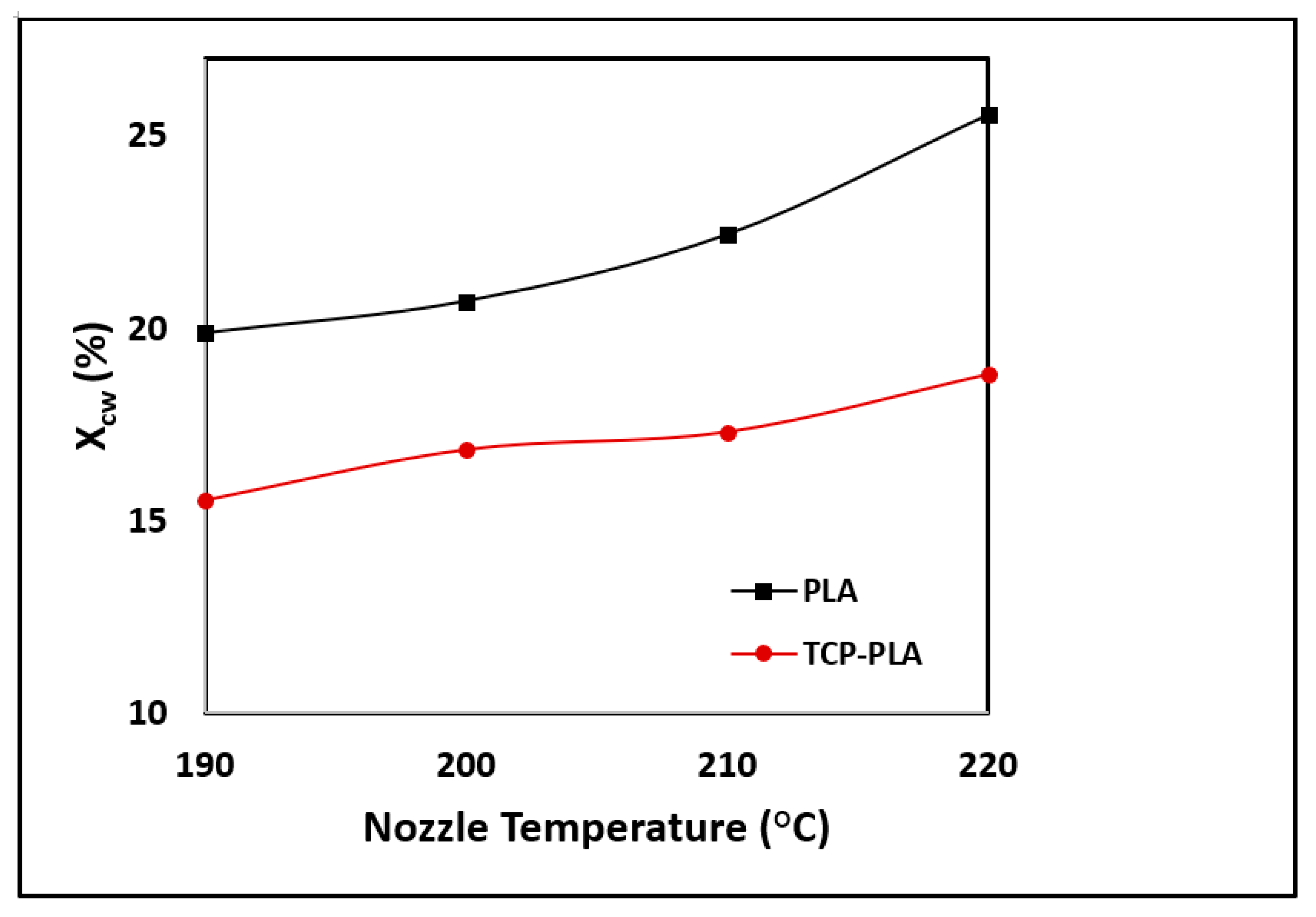
| Specimen | Nozzle Temperature (°C) | Tg (°C) | Tc (°C) | Tm (°C) | Hm (J/g) | Xcw (%) |
|---|---|---|---|---|---|---|
| PLA | 190 | 61.58 | 122.86 | 152.3 | 18.47 | 19.86 |
| 200 | 65.8 | 122.98 | 152.8 | 19.242 | 20.69 | |
| 210 | 68.63 | 121.28 | 151.82 | 20.864 | 22.434 | |
| 220 | 70.2 | 121.14 | 151.29 | 23.771 | 25.56 | |
| TCP–PLA | 190 | 60.52 | 125.1 | 150.85 | 13.704 | 15.51 |
| 200 | 60.19 | 124.39 | 151.01 | 14.87 | 16.83 | |
| 210 | 60.68 | 125.05 | 151.1 | 15.28 | 17.29 | |
| 220 | 62.92 | 124.58 | 150.67 | 16.603 | 18.792 |
Publisher’s Note: MDPI stays neutral with regard to jurisdictional claims in published maps and institutional affiliations. |
© 2022 by the authors. Licensee MDPI, Basel, Switzerland. This article is an open access article distributed under the terms and conditions of the Creative Commons Attribution (CC BY) license (https://creativecommons.org/licenses/by/4.0/).
Share and Cite
Elhattab, K.; Bhaduri, S.B.; Sikder, P. Influence of Fused Deposition Modelling Nozzle Temperature on the Rheology and Mechanical Properties of 3D Printed β-Tricalcium Phosphate (TCP)/Polylactic Acid (PLA) Composite. Polymers 2022, 14, 1222. https://0-doi-org.brum.beds.ac.uk/10.3390/polym14061222
Elhattab K, Bhaduri SB, Sikder P. Influence of Fused Deposition Modelling Nozzle Temperature on the Rheology and Mechanical Properties of 3D Printed β-Tricalcium Phosphate (TCP)/Polylactic Acid (PLA) Composite. Polymers. 2022; 14(6):1222. https://0-doi-org.brum.beds.ac.uk/10.3390/polym14061222
Chicago/Turabian StyleElhattab, Karim, Sarit B. Bhaduri, and Prabaha Sikder. 2022. "Influence of Fused Deposition Modelling Nozzle Temperature on the Rheology and Mechanical Properties of 3D Printed β-Tricalcium Phosphate (TCP)/Polylactic Acid (PLA) Composite" Polymers 14, no. 6: 1222. https://0-doi-org.brum.beds.ac.uk/10.3390/polym14061222