
Smart Anticorrosion Coatings Based on Poly(phenylene methylene): An Assessment of the Intrinsic Self-Healing Behavior of the Copolymer

 , , , and
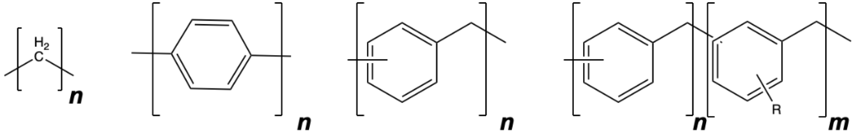
Abstract
:1. Introduction
2. Experimental
2.1. Materials
2.2. Preparation of Blended PPM
2.3. Synthesis of PPM Copolymer
2.4. Preparation of Coatings
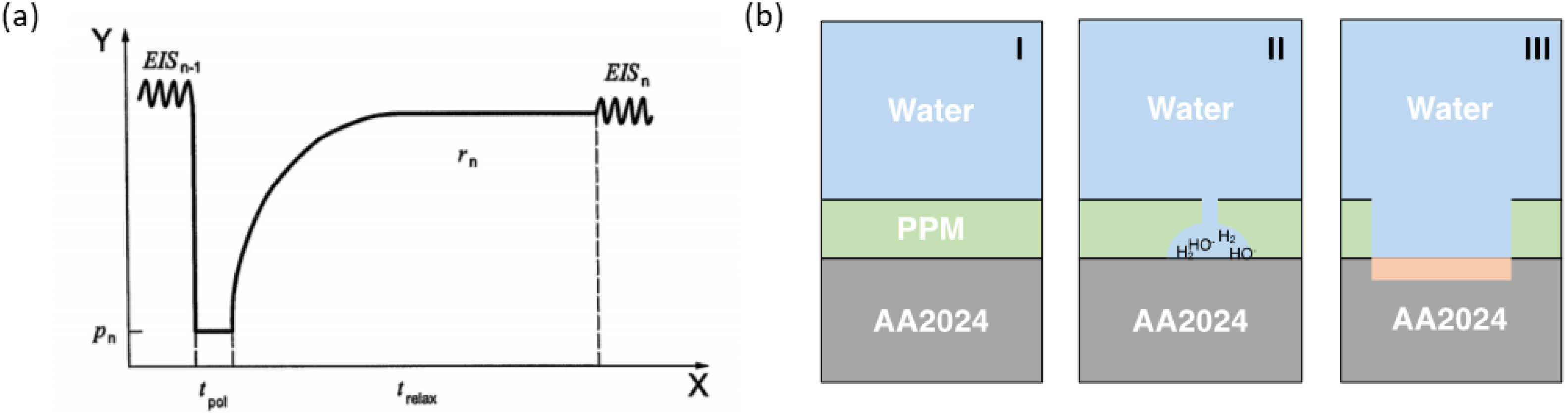
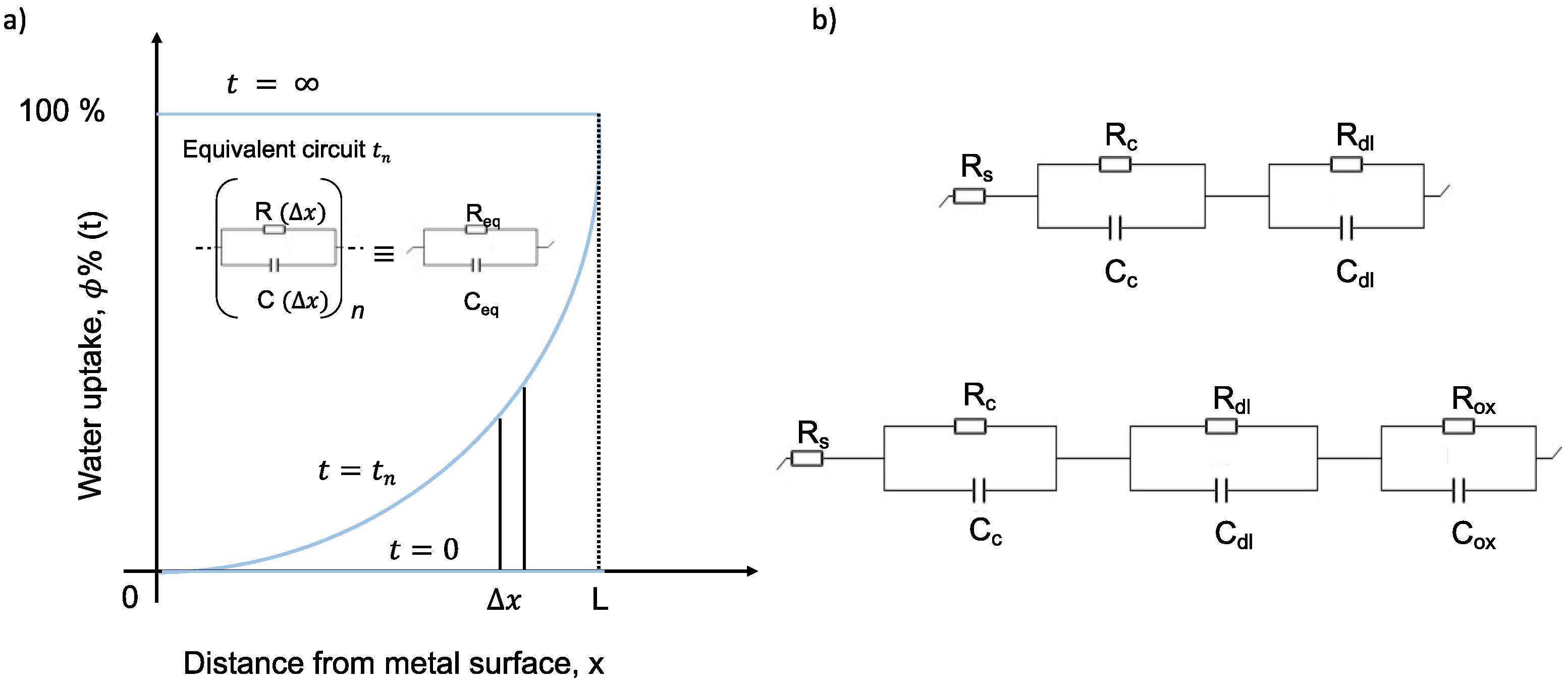
2.5. EIS and ACET
3. Results
3.1. 50 μm Thick Coatings
3.2. 30 μm Thick Coatings
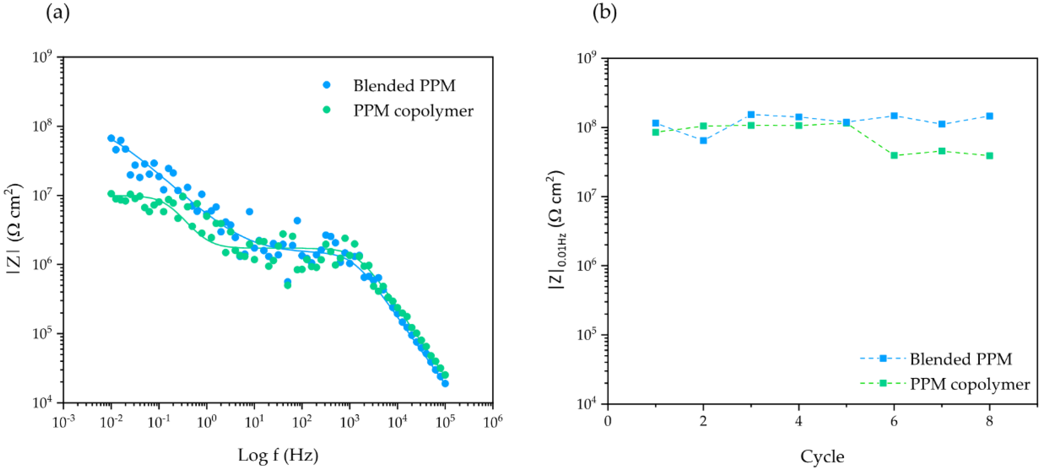
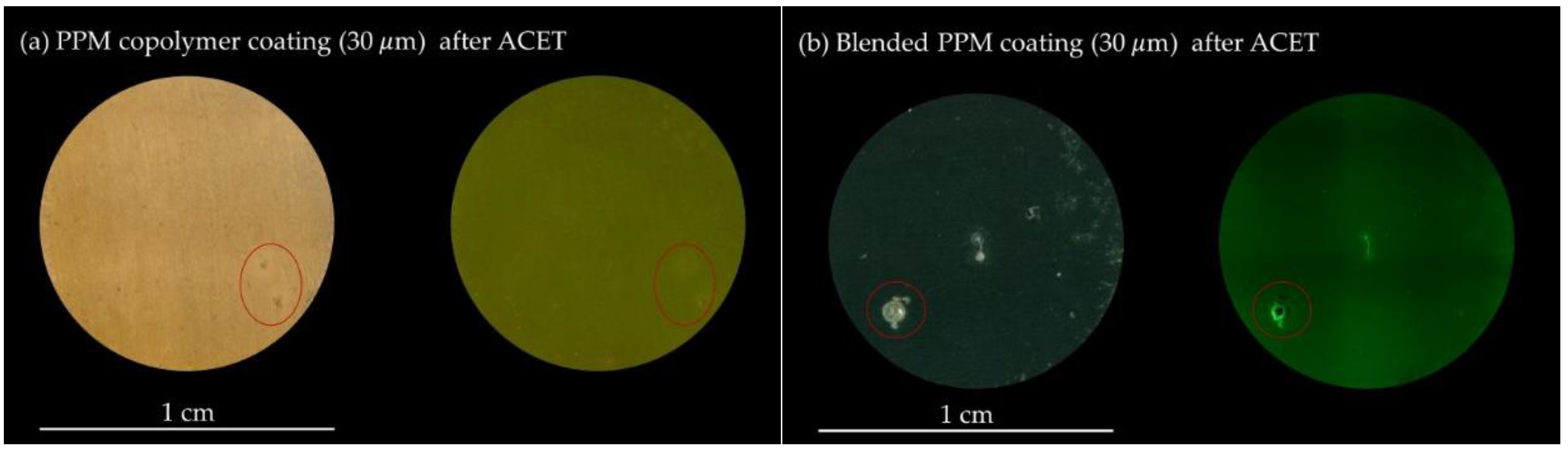
3.2.1. Behaviour under Accelerated Aging Conditions
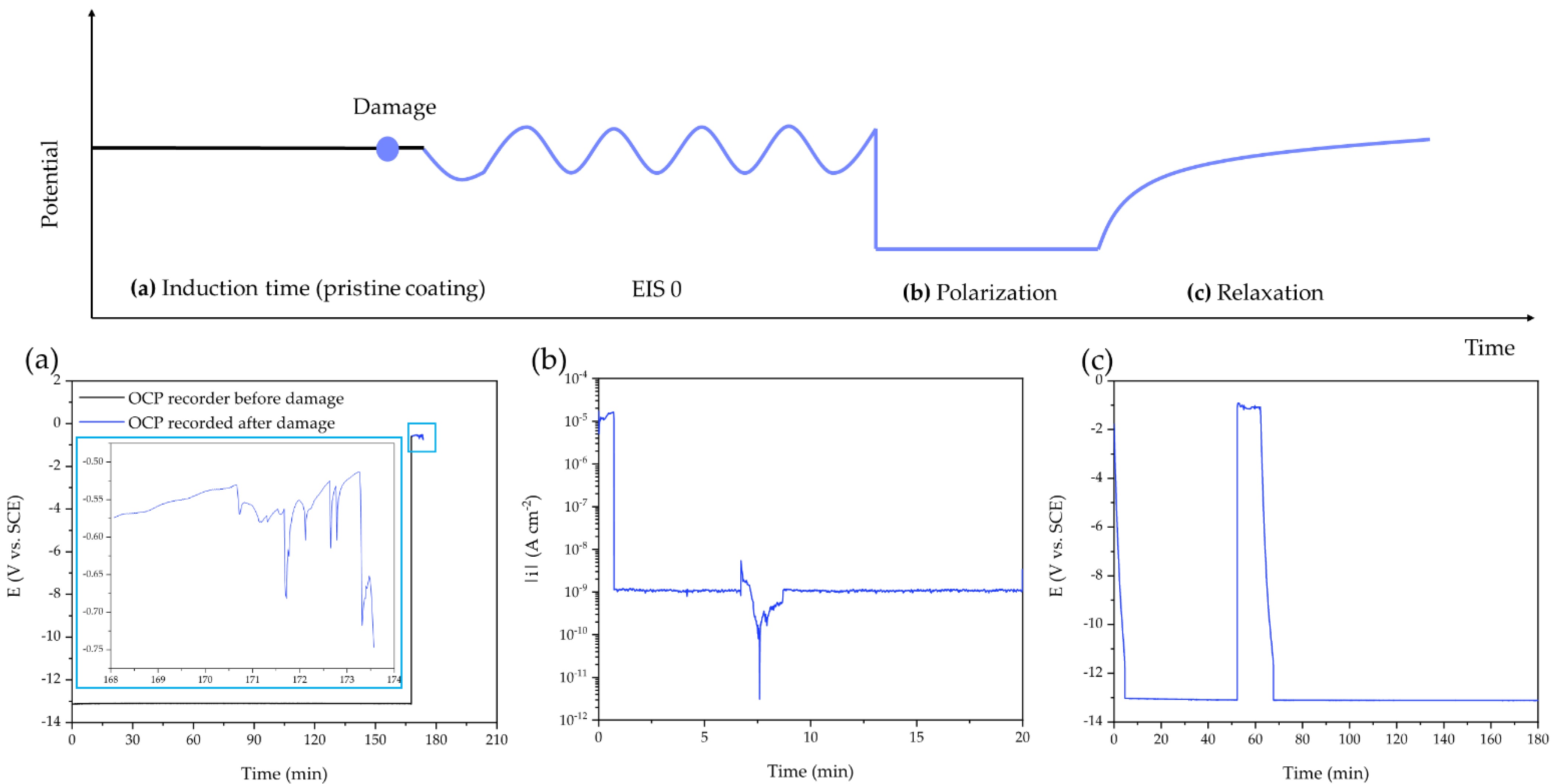
3.2.2. Self-Healing Assessment on PPM Copolymer Coating after Mechanical Damage
4. Discussion
4.1. Effect of the Formulation and the Thickness of PPM-Based Coatings
4.2. Polymer Rearrangement under Localized Corrosion
5. Conclusions
Supplementary Materials
Author Contributions
Funding
Acknowledgments
Conflicts of Interest
References
- Teng, D.G.; Wei, X.Y.; Yang, Z.; Zhu, Q.J.; Gao, H.S.; Li, J.; Zhang, M.; Zong, Z.; Kang, Y.H. Synthesis of poly(phenylene methylenes) via a AlCl3 -mediated Friedel–Craft alkylation of multi-substituted benzyl bromide with benzene. J. Appl. Polym. Sci. 2020, 137, 4–11. [Google Scholar] [CrossRef]
- Teng, D.G.; Wei, X.Y.; Yang, Z.; Zong, Z.M. α-Fe2O3 /Attapulgite-mediated reaction of benzyl chloride: Synthesis of poly(phenylene methylene). J. Polym. Sci. Part A Polym. Chem. 2018, 56, 2280–2285. [Google Scholar] [CrossRef]
- Hino, M.; Arata, K. Iron Oxide as an Effective Catalyst for the Polycondensation of Benzyl Chloride, the Formation of Para-Substituted Polybenzyl. Chem. Lett. 1979, 8, 1141–1144. [Google Scholar] [CrossRef]
- Dreyer, D.R.; Jarvis, K.A.; Ferreira, P.J.; Bielawski, C.W. Graphite Oxide as a Dehydrative Polymerization Catalyst: A One-Step Synthesis of Carbon-Reinforced Poly (Phenylene methylene) Composites. Macromolecules 2011, 44, 7659–7667. [Google Scholar] [CrossRef]
- Tsonis, C.P. Homogeneous catalytic polymerization of benzyl chloride leading to linear high molecular weight polymers: An elusive goal. J. Mol. Catal. 1990, 57, 313–323. [Google Scholar] [CrossRef]
- Som, A.; Ramakrishnan, S. Linear soluble polybenzyls. J. Polym. Sci. Part A Polym. Chem. 2003, 41, 2345–2353. [Google Scholar] [CrossRef] [Green Version]
- Shriner, R.L.; Berger, A. Condensation products from Benzyl alcohol. Polybenzyls. J. Org. Chem. 1941, 6, 305–318. [Google Scholar] [CrossRef]
- Steiger, D.; Tervoort, T.; Weder, C.; Smith, P. Poly(p-phenylene alkylene)s–A forgotten class of polymers. Macromol. Rapid Commun. 2000, 21, 405–422. [Google Scholar] [CrossRef]
- D’Elia, M.F.; Braendle, A.; Schweizer, T.B.; Ortenzi, M.A.; Trasatti, S.P.M.; Niederberger, M.; Caseri, W. Poly(Phenylene Methylene): A Multifunctional Material for Thermally Stable, Hydrophobic, Fluorescent, Corrosion-Protective Coatings. Coatings 2018, 8, 274. [Google Scholar] [CrossRef] [Green Version]
- D’Elia, M.F.; Magni, M.; Trasatti, S.P.M.; Schweizer, T.B.; Niederberger, M.; Caseri, W. Poly(phenylene methylene)-Based Coatings for Corrosion Protection: Replacement of Additives by Use of Copolymers. Appl. Sci. 2019, 9, 3551. [Google Scholar] [CrossRef] [Green Version]
- Braendle, A.; Schwendimann, P.; Niederberger, M.; Caseri, W.R. Synthesis and fractionation of poly(phenylene methylene). J. Polym. Sci. Part A Polym. Chem. 2017, 56, 309–318. [Google Scholar] [CrossRef]
- Braendle, A.; Perevedentsev, A.; Cheetham, N.J.; Stavrinou, P.N.; Schachner, J.A.; Niederberger, M.; Caseri, W.R.; Mösch-Zanetti, N.C. Homoconjugation in poly(phenylene methylene)s: A case study of non-π-conjugated polymers with unexpected fluorescent properties. J. Polym. Sci. Part B Polym. Phys. 2017, 55, 707–720. [Google Scholar] [CrossRef]
- Puig, M.; Gimeno, M.; Gracenea, J.; Suay, J. Anticorrosive properties enhancement in powder coating duplex systems by means of ZMP anticorrosive pigment. Assessment by electrochemical techniques. Prog. Org. Coat. 2014, 77, 1993–1999. [Google Scholar] [CrossRef]
- Njoku, D.I.; Cui, M.; Xiao, H.; Shang, B.; Li, Y. Understanding the anticorrosive protective mechanisms of modified epoxy coatings with improved barrier, active and self-healing functionalities: EIS and spectroscopic techniques. Sci. Rep. 2017, 7, 15597. [Google Scholar] [CrossRef] [PubMed]
- Moreno, C.; Hernández, S.; Santana, J.J.; González-Guzmán, J.; Souto, R.M.; González, S. Characterization of Water Uptake by Organic Coatings Used for the Corrosion Protection of Steel as Determined from Capacitance Measurements. Int. J. Electro-Chem. Sci. 2012, 7, 8444–8457. Available online: http://riull.ull.es/xmlui/handle/915/19025 (accessed on 23 July 2022).
- Lacombre, C.V.; Bouvet, G.; Trinh, D.; Mallarino, S.; Touzain, S. Water uptake in free films and coatings using the Brasher and Kingsbury equation: A possible explanation of the different values obtained by electrochemical Impedance spectroscopy and gravimetry. Electrochim. Acta 2017, 231, 162–170. [Google Scholar] [CrossRef]
- Van der Wel, G.; Adan, O. Moisture in organic coatings—A review. Prog. Org. Coat. 1999, 37, 1–14. [Google Scholar] [CrossRef]
- Negele, O.; Funke, W. Internal stress and wet adhesion of organic coatings. Prog. Org. Coat. 1996, 28, 285–289. [Google Scholar] [CrossRef]
- Brasher, D.M.; Kingsbury, A.H. Electrical measurements in the study of immersed paint coatings on metal. I. Comparison between capacitance and gravimetric methods of estimating water-uptake. J. Appl. Chem. 1954, 4, 62–72. [Google Scholar] [CrossRef]
- De Rosa, L. Monitoring Degradation of Single and Multilayer Organic Coatings. J. Electrochem. Soc. 1998, 145, 3830–3838. [Google Scholar] [CrossRef]
- Bellucci, F.; Nicodemo, L. Water Transport in Organic Coatings. Corrosion 1993, 49, 235–247. [Google Scholar] [CrossRef]
- Calderón-Gutierrez, J.A.; Bedoya-Lora, F.E. Barrier Property Determination and Lifetime Prediction by Electrochemical Impedance Spectroscopy of a High Performance Organic Coating. DYNA 2014, 81, 97. [Google Scholar] [CrossRef]
- Aghili, M.; Yazdi, M.K.; Ranjbar, Z.; Jafari, S.H. Anticorrosion performance of electro-deposited epoxy/ amine functionalized graphene oxide nanocomposite coatings. Corros. Sci. 2021, 179, 109143. [Google Scholar] [CrossRef]
- Hollaender, J. Rapid assessment of food/package interactions by electrochemical impedance spectroscopy (EIS). Food Addit. Contam. 1997, 14, 617–626. [Google Scholar] [CrossRef]
- Molina, J.; Puig, M.; Gimeno, M.; Izquierdo, R.; Gracenea, J.; Suay, J. Influence of zinc molybdenum phosphate pigment on coatings performance studied by electrochemical methods. Prog. Org. Coat. 2016, 97, 244–253. [Google Scholar] [CrossRef] [Green Version]
- García, S.; Suay, J. Application of electrochemical techniques to study the effect on the anticorrosive properties of the addition of ytterbium and erbium triflates as catalysts on a powder epoxy network. Prog. Org. Coat. 2006, 57, 273–281. [Google Scholar] [CrossRef]
- International Organization for Standardization. ISO 17463:2014(en); Paints and Varnishes—Guidelines for the Determination of Anticorrosive Properties of Organic Coatings by Accelerated Cyclic Electrochemical Technique; International Organization for Standardization: Geneva, Switzerland, 2015. [Google Scholar]
- Scully, J.R. Electrochemical Impedance of Organic-Coated Steel: Correlation of Impedance Parameters with Long-Term Coating Deterioration. J. Electrochem. Soc. 1989, 136, 979–990. [Google Scholar] [CrossRef]
- Graedel, T.E. Corrosion Mechanisms for Silver Exposed to the Atmosphere. J. Electrochem. Soc. 1992, 139, 1963–1970. [Google Scholar] [CrossRef]
- Skale, S.; Doleček, V.; Slemnik, M. Substitution of the constant phase element by Warburg impedance for protective coatings. Corros. Sci. 2007, 49, 1045–1055. [Google Scholar] [CrossRef]
- Hitz, C.; Lasia, A. Experimental study and modeling of impedance of the her on porous Ni electrodes. J. Electroanal. Chem. 2001, 500, 213–222. [Google Scholar] [CrossRef]
- Apelblat, A.; Korin, E. The molar enthalpies of solution and vapour pressures of saturated aqueous solutions of aluminium chloride, aluminium nitrate and aluminium sulphate. J. Chem. Thermodyn. 2002, 34, 1919–1927. [Google Scholar] [CrossRef]
- Zeng, W.; Chen, Q.; Chen, X. Determination of the standard enthalpy of formation of aqueous aluminum ion, Al3+ (aq). Geochim. Cosmochim. Acta 1994, 58, 3511–3514. [Google Scholar]
- Sørensen, P.A.; Dam-Johansen, K.; Weinell, C.; Kiil, E.S. Cathodic delamination of seawater-immersed anticorrosive coatings: Mapping of parameters affecting the rate. Prog. Org. Coat. 2010, 68, 283–292. [Google Scholar] [CrossRef]


Publisher’s Note: MDPI stays neutral with regard to jurisdictional claims in published maps and institutional affiliations. |
© 2022 by the authors. Licensee MDPI, Basel, Switzerland. This article is an open access article distributed under the terms and conditions of the Creative Commons Attribution (CC BY) license (https://creativecommons.org/licenses/by/4.0/).
Share and Cite
D’Elia, M.F.; Magni, M.; Romanò, T.; Trasatti, S.P.M.; Niederberger, M.; Caseri, W.R. Smart Anticorrosion Coatings Based on Poly(phenylene methylene): An Assessment of the Intrinsic Self-Healing Behavior of the Copolymer. Polymers 2022, 14, 3457. https://0-doi-org.brum.beds.ac.uk/10.3390/polym14173457
D’Elia MF, Magni M, Romanò T, Trasatti SPM, Niederberger M, Caseri WR. Smart Anticorrosion Coatings Based on Poly(phenylene methylene): An Assessment of the Intrinsic Self-Healing Behavior of the Copolymer. Polymers. 2022; 14(17):3457. https://0-doi-org.brum.beds.ac.uk/10.3390/polym14173457
Chicago/Turabian StyleD’Elia, Marco F., Mirko Magni, Thomas Romanò, Stefano P. M. Trasatti, Markus Niederberger, and Walter R. Caseri. 2022. "Smart Anticorrosion Coatings Based on Poly(phenylene methylene): An Assessment of the Intrinsic Self-Healing Behavior of the Copolymer" Polymers 14, no. 17: 3457. https://0-doi-org.brum.beds.ac.uk/10.3390/polym14173457