
Characterization of Hybrid FRP Composite Produced from Recycled PET and CFRP

 and
and
Abstract
:1. Introduction
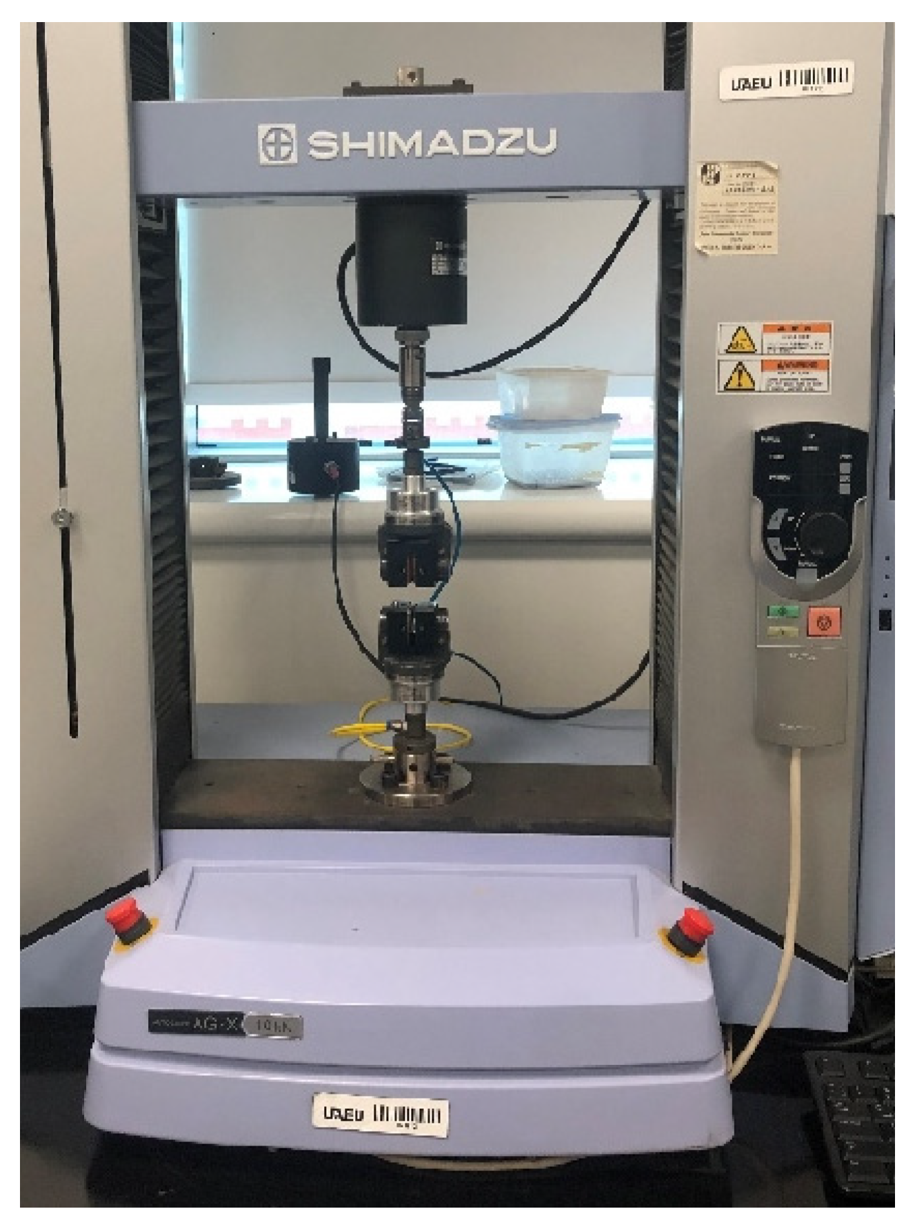
2. Materials and Methods
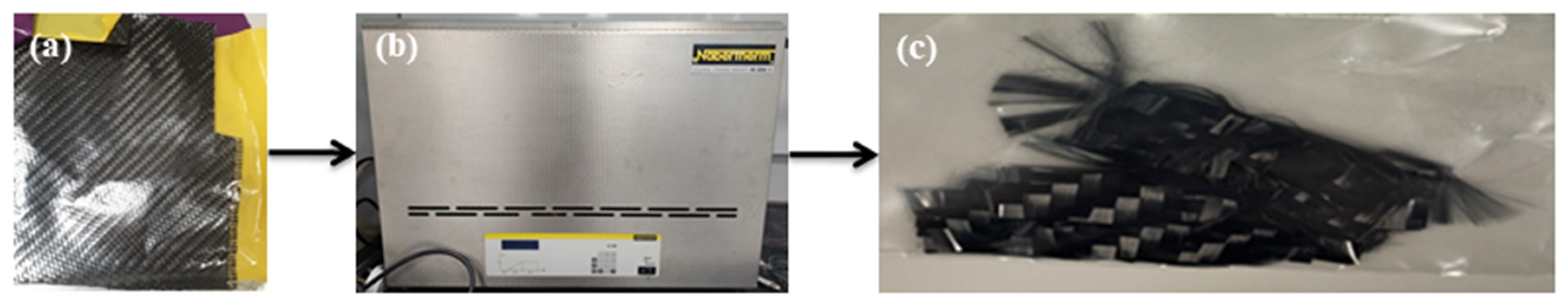
2.1. Pyrolysis
- Chemical Process
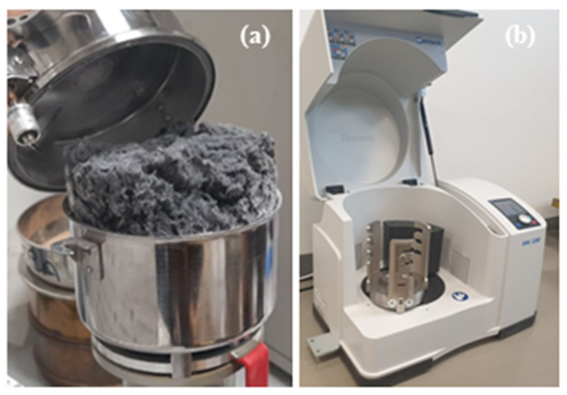
2.2. Milling Process
2.3. Planetary Ball Mill PM 100
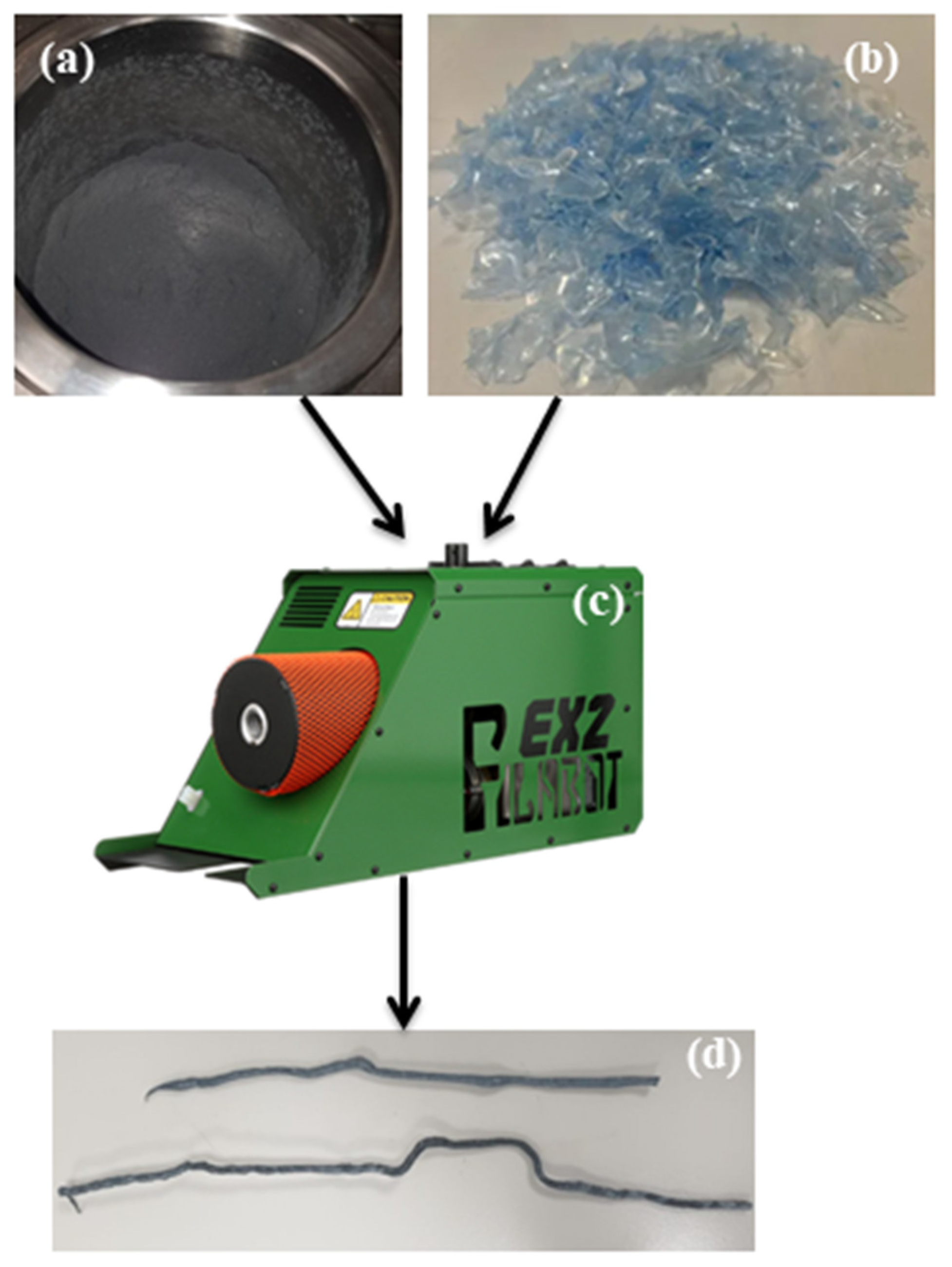
2.4. Extrusion
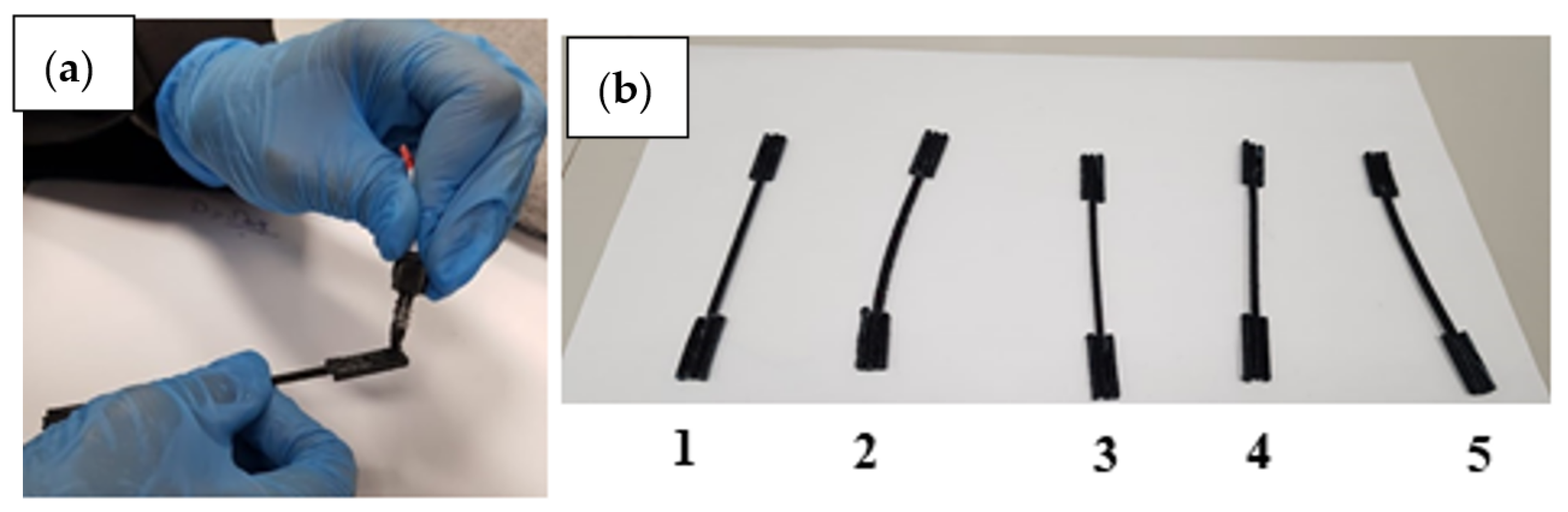
2.5. Material Process
3. Results
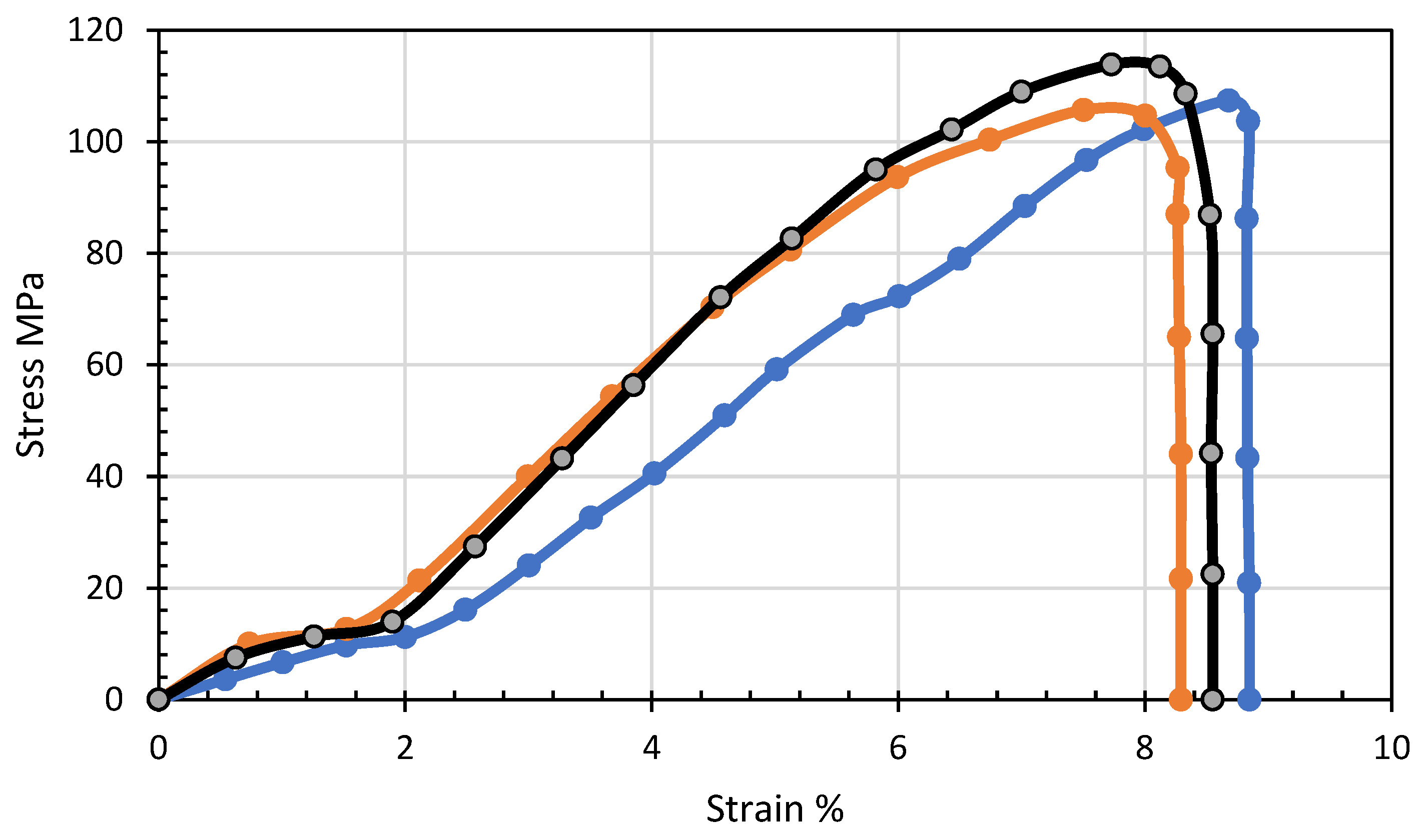
3.1. Mechanical Characteristics
3.2. Mechanical Characterization
3.3. SEM
4. Conclusions
Author Contributions
Funding
Institutional Review Board Statement
Informed Consent Statement
Data Availability Statement
Acknowledgments
Conflicts of Interest
References
- Huang, X. Fabrication and Properties of Carbon Fibers. Materials 2009, 2, 2369–2403. [Google Scholar] [CrossRef] [Green Version]
- Gholampoor, M.; Movassagh-Alanagh, F.; Salimkhani, H. Fabrication of nano-Fe 3 O 4 3D structure on carbon fibers as a microwave absorber and EMI shielding composite by modified EPD method. Solid State Sci. 2017, 64, 51–61. [Google Scholar] [CrossRef]
- Marshall, D.; Cox, B.; Evans, A. The mechanics of matrix cracking in brittle-matrix fiber composites. Acta Met. 1985, 33, 2013–2021. [Google Scholar] [CrossRef]
- Lu, C.; Wang, J.; Leung, C.K.; Yao, Y.; Yu, B. Micromechanics-based model of single crack propagation in Engineered cementitious composites (ECC). Constr. Build. Mater. 2023, 369, 130519. [Google Scholar] [CrossRef]
- Gangineni, P.K.; Yandrapu, S.; Ghosh, S.K.; Anand, A.; Prusty, R.K.; Ray, B.C. Mechanical behavior of Graphene decorated carbon fiber reinforced polymer composites: An assessment of the influence of functional groups. Compos. Part A Appl. Sci. Manuf. 2019, 122, 36–44. [Google Scholar] [CrossRef]
- Wang, C.; Li, J.; Sun, S.; Li, X.; Zhao, F.; Jiang, B.; Huang, Y. Electrophoretic deposition of graphene oxide on continuous carbon fibers for reinforcement of both tensile and interfacial strength. Compos. Sci. Technol. 2016, 135, 46–53. [Google Scholar] [CrossRef]
- Lionetto, F. Carbon Fiber Reinforced Polymers. Materials 2021, 14, 5545. [Google Scholar] [CrossRef]
- Abas, N.; Kalair, A.R.; Khan, N.; Haider, A.; Saleem, Z.; Saleem, M.S. Natural and synthetic refrigerants, global warming: A review. Renew. Sustain. Energy Rev. 2018, 90, 557–569. [Google Scholar] [CrossRef]
- Shi, J.; Han, J.; Xu, J. Effect of fiber constituent in matrix on cyclic behavior of PVA-Steel hybrid Fiber-Reinforced cementitious composites columns with mild steel rebar. Constr. Build. Mater. 2022, 359, 129514. [Google Scholar] [CrossRef]
- Xiaoyong, Z.; Shihan, C.; Zhouhua, W.; Huiyun, Q.; Guixing, L.; Xiaolei, W.; Yu, C. Research on mechanical properties of ultra-high performance fiber reinforced cement-based composite after elevated temperature. Compos. Struct. 2022, 291, 115584. [Google Scholar] [CrossRef]
- Singh, A.K.; Bedi, R.; Kaith, B.S. Composite materials based on recycled polyethylene terephthalate and their properties—A comprehensive review. Compos. Part B Eng. 2021, 219, 108928. [Google Scholar] [CrossRef]
- Stănescu, M.M.; Bolcu, D. A Study of Some Mechanical Properties of Composite Materials with a Dammar-Based Hybrid Matrix and Reinforced by Waste Paper. Polymers 2020, 12, 1688. [Google Scholar] [CrossRef]
- Öchsner, A.; Altenbach, H. Advanced Structured Materials Engineering Design Applications III Structures, Materials and Processes. Available online: http://0-www-springer-com.brum.beds.ac.uk/series/8611 (accessed on 15 May 2023).
- Höglund, R. Modelling of a High-Performance Vehicle in MATLAB/Simulink and Canopy Simulations; MathWorks: Natick, MA, USA, 2022. [Google Scholar]
- Dhiman, B.; Guleria, V.; Sharma, P. Applications and Future Trends of Carbon Fiber Reinforced Polymer Composites: A Review. Int. Res. J. Eng. Technol. 2020, 10, 1883–1889. [Google Scholar]
- Koçer, M.; Boğa, A.R.; Öztürk, M. Investigation of reinforcement corrosion effects in RC columns produced with blast furnace slag and fly ash under reversed-cyclic lateral loading tests. Eng. Struct. 2021, 245, 112866. [Google Scholar] [CrossRef]
- Boucher, G. Book Reviews: Book Reviews. Crit. Sociol. 2011, 37, 493–497. [Google Scholar] [CrossRef]
- Muflikhun, M.A.; Fiedler, B. Failure Prediction and Surface Characterization of GFRP Laminates: A Study of Stepwise Loading. Polymers 2022, 14, 4322. [Google Scholar] [CrossRef]
- Muflikhun, M.A.; Yokozeki, T. Systematic analysis of fractured specimens of composite laminates: Different perspectives between tensile, flexural, Mode I, and Mode II test. Int. J. Light Mater. Manuf. 2023, 6, 329–343. [Google Scholar] [CrossRef]
- Muflikhun, M.A.; Higuchi, R.; Yokozeki, T.; Aoki, T. The evaluation of failure mode behavior of CFRP/Adhesive/SPCC hybrid thin laminates under axial and flexural loading for structural applications. Compos. Part B Eng. 2020, 185, 107747. [Google Scholar] [CrossRef]
- Yu, J.; Chen, Y.; Leung, C.K. Micromechanical modeling of crack-bridging relations of hybrid-fiber Strain-Hardening Cementitious Composites considering interaction between different fibers. Constr. Build. Mater. 2018, 182, 629–636. [Google Scholar] [CrossRef]
- Deokar, S.; Visal, S. A Review Paper on Properties of Carbon Fiber Reinforced Polymers. IJRSIT 2016, 2, 238–243. [Google Scholar]
- Worku, B.G.; Wubieneh, T.A. Mechanical Properties of Composite Materials from Waste Poly(ethylene terephthalate) Reinforced with Glass Fibers and Waste Window Glass. Int. J. Polym. Sci. 2021, 2021, 226. [Google Scholar] [CrossRef]
- Zheng, H.; Zhang, W.; Li, B.; Zhu, J.; Wang, C.; Song, G.; Wu, G.; Yang, X.; Huang, Y.; Ma, L. Recent advances of interphases in carbon fiber-reinforced polymer composites: A review. Compos. Part B Eng. 2022, 233, 109639. [Google Scholar] [CrossRef]
- Ma, L.; Li, N.; Wu, G.; Song, G.; Li, X.; Han, P.; Wang, G.; Huang, Y. Interfacial enhancement of carbon fiber composites by growing TiO2 nanowires onto amine-based functionalized carbon fiber surface in supercritical water. Appl. Surf. Sci. 2018, 433, 560–567. [Google Scholar] [CrossRef]
- Wang, B.; Duan, Y.; Zhang, J. A controllable interface performance through varying ZnO nanowires dimensions on the carbon fibers. Appl. Surf. Sci. 2016, 389, 96–102. [Google Scholar] [CrossRef]
- Yu, J.; Chen, Y.; Leung, C.K. Mechanical performance of Strain-Hardening Cementitious Composites (SHCC) with hybrid polyvinyl alcohol and steel fibers. Compos. Struct. 2019, 226, 111198. [Google Scholar] [CrossRef]
- Chen, X.; Xu, H.; Liu, D.; Yan, C.; Zhu, Y. A facile one-pot fabrication of polyphosphazene microsphere/carbon fiber hybrid reinforcement and its effect on the interfacial adhesion of epoxy composites. Appl. Surf. Sci. 2017, 410, 530–539. [Google Scholar] [CrossRef]
- Lu, Z.; Ahanif, A.; Sun, G.; Liang, R.; Parthasarathy, P.; Li, Z. Highly dispersed graphene oxide electrodeposited carbon fiber reinforced cement-based materials with enhanced mechanical properties. Cem. Concr. Compos. 2018, 87, 220–228. [Google Scholar] [CrossRef]
- Zhu, P.; Ruan, F.; Bao, L. Preparation of polyetherimide nanoparticles on carbon fiber surface via evaporation induced surface modification method and its effect on tensile strength and interfacial shear strength. Appl. Surf. Sci. 2018, 454, 54–60. [Google Scholar] [CrossRef]
- Qiu, J.; Lim, X.-N.; Yang, E.-H. Fatigue-induced deterioration of the interface between micro-polyvinyl alcohol (PVA) fiber and cement matrix. Cem. Concr. Res. 2016, 90, 127–136. [Google Scholar] [CrossRef]
- Dong, J.; Jia, C.; Wang, M.; Fang, X.; Wei, H.; Xie, H.; Zhang, T.; He, J.; Jiang, Z.; Huang, Y. Improved mechanical properties of carbon fiber-reinforced epoxy composites by growing carbon black on carbon fiber surface. Compos. Sci. Technol. 2017, 149, 75–80. [Google Scholar] [CrossRef]
- Kitamura, H.; Sekido, M.; Takeuchi, H.; Ohno, M. The method for surface functionalization of single-walled carbon nanotubes with fuming nitric acid. Carbon 2011, 49, 3851–3856. [Google Scholar] [CrossRef]
- Chen, C.-M.; Zhang, Q.; Yang, M.-G.; Huang, C.-H.; Yang, Y.-G.; Wang, M.-Z. Structural evolution during annealing of thermally reduced graphene nanosheets for application in supercapacitors. Carbon 2012, 50, 3572–3584. [Google Scholar] [CrossRef]
- Felisberto, M.; Tzounis, L.; Sacco, L.; Stamm, M.; Candal, R.; Rubiolo, G.H.; Goyanes, S. Carbon nanotubes grown on carbon fiber yarns by a low temperature CVD method: A significant enhancement of the interfacial adhesion between carbon fiber/epoxy matrix hierarchical composites. Compos. Commun. 2017, 3, 33–37. [Google Scholar] [CrossRef]
- Pozegic, T.; Hamerton, I.; Anguita, J.V.; Tang, W.; Ballocchi, P.; Jenkins, P.; Silva, S.R.P. Low temperature growth of carbon nanotubes on carbon fibre to create a highly networked fuzzy fibre reinforced composite with superior electrical conductivity. Carbon 2014, 74, 319–328. [Google Scholar] [CrossRef]
- Lee, J.U.; Park, B.; Kim, B.-S.; Bae, D.-R.; Lee, W. Electrophoretic deposition of aramid nanofibers on carbon fibers for highly enhanced interfacial adhesion at low content. Compos. Part A Appl. Sci. Manuf. 2016, 84, 482–489. [Google Scholar] [CrossRef]
- Malekimoghadam, R.; Hosseini, S.A.; Icardi, U. Bending analysis of carbon nanotube coated–fiber multi-scale composite beams using the refined zigzag theory. Aerosp. Sci. Technol. 2023, 138, 108328. [Google Scholar] [CrossRef]
- Cook, G.M.; Tessler, A. A {3,2}-order bending theory for laminated composite and sandwich beams. Compos. Part B Eng. 1998, 29, 565–576. [Google Scholar] [CrossRef] [Green Version]
- Christensen, R.; Lo, K. Solutions for effective shear properties in three phase sphere and cylinder models. J. Mech. Phys. Solids 1979, 27, 315–330. [Google Scholar] [CrossRef]
- Shakhlavi, S.J. On nonlinear damping effects with nonlinear temperature-dependent properties for an axial thermo-viscoelastic rod. Int. J. Non-linear Mech. 2023, 153, 104418. [Google Scholar] [CrossRef]
- Chauhan, A.; Bedi, H.S.; Agnihotri, P.K. Enhancing aging resistance of glass fiber/epoxy composites using carbon nanotubes. Mater. Chem. Phys. 2022, 291, 104418. [Google Scholar] [CrossRef]
- Qu, C.-B.; Xiao, H.-M.; Huang, G.-W.; Li, N.; Li, M.; Li, F.; Li, Y.-Q.; Liu, Y.; Fu, S.-Y. Effects of cryo-thermal cycling on interlaminar shear strength and thermal expansion coefficient of carbon fiber/graphene oxide-modified epoxy composites. Compos. Commun. 2022, 32, 104418. [Google Scholar] [CrossRef]
- Ma, P.-C.; Siddiqui, N.A.; Marom, G.; Kim, J.-K. Dispersion and functionalization of carbon nanotubes for polymer-based nanocomposites: A review. Compos. Part A Appl. Sci. Manuf. 2010, 41, 1345–1367. [Google Scholar] [CrossRef]
- Barbosa, A.P.C.; Fulco, A.P.P.; Guerra, E.S.; Arakaki, F.K.; Tosatto, M.; Costa, M.C.B.; Melo, J.D.D. Accelerated aging effects on carbon fiber/epoxy composites. Compos. Part B Eng. 2017, 110, 298–306. [Google Scholar] [CrossRef]
- Nicholas, J.; Mohamed, M.; Dhaliwal, G.; Anandan, S.; Chandrashekhara, K. Effects of accelerated environmental aging on glass fiber reinforced thermoset polyurethane composites. Compos. Part B Eng. 2016, 94, 370–378. [Google Scholar] [CrossRef]
- Khan, S.; Bedi, H.S.; Agnihotri, P.K. Augmenting mode-II fracture toughness of carbon fiber/epoxy composites through carbon nanotube grafting. Eng. Fract. Mech. 2018, 204, 211–220. [Google Scholar] [CrossRef]
- Grammatikos, S.; Paipetis, A. On the electrical properties of multi scale reinforced composites for damage accumulation monitoring. Compos. Part B Eng. 2012, 43, 2687–2696. [Google Scholar] [CrossRef]
- Seo, D.-C.; Lee, J.-J. Damage detection of CFRP laminates using electrical resistance measurement and neural network. Compos. Struct. 1999, 47, 525–530. [Google Scholar] [CrossRef]
- Qin, J.; Wang, C.; Yao, Z.; Ma, Z.; Cui, X.; Gao, Q.; Wang, Y.; Wang, Q.; Wei, H. Mechanical property deterioration and defect repair factors of carbon fibers during the continuous growth of carbon nanotubes by chemical vapor deposition. Ceram. Int. 2021, 47, 19213–19219. [Google Scholar] [CrossRef]
- Ouyang, Z.; Rao, Q.; Peng, X. Significantly improving thermal conductivity of carbon fiber polymer composite by weaving highly conductive films. Compos. Part A Appl. Sci. Manuf. 2022, 163, 107183. [Google Scholar] [CrossRef]
- Yadav, S.K.; Kumar, A.; Mehta, N. Tailoring of physical properties of glassy selenium (g-Se) by using multi-walled carbon nanotubes (MWCNTs). Mater. Sci. Eng. B 2023, 290, 116310. [Google Scholar] [CrossRef]
- Wang, S.; Haldane, D.; Gallagher, P.; Liu, T.; Liang, R.; Koo, J.H. Heterogeneously structured conductive carbon fiber composites by using multi-scale silver particles. Compos. Part B Eng. 2014, 61, 172–180. [Google Scholar] [CrossRef]
- Suzuki, T.; Umehara, H. Pitch-based carbon fiber microstructure and texture and compatibility with aluminum coated using chemical vapor deposition. Carbon 1999, 37, 47–59. [Google Scholar] [CrossRef]
- Yang, W.; Zhou, L.; Peng, K.; Zhu, J.; Wan, L. Effect of tungsten addition on thermal conductivity of graphite/copper composites. Compos. Part B Eng. 2013, 55, 1–4. [Google Scholar] [CrossRef]
- Lee, S.B.; Matsunaga, K.; Ikuhara, Y. Effect of alloying elements on the interfacial bonding strength and electric conductivity of carbon nano-fiber reinforced Cu matrix composites. Mater. Sci. Eng. A 2007, 449-451, 778–781. [Google Scholar] [CrossRef]
- Xia, Y.; Song, Y.-Q.; Lin, C.-G.; Cui, S.; Fang, Z.-Z. Effect of carbide formers on microstructure and thermal conductivity of diamond-Cu composites for heat sink materials. Trans. Nonferrous Met. Soc. China 2009, 19, 1161–1166. [Google Scholar] [CrossRef]
- Nepal, S.; Das, B.; Das, M.K.; Das Sarkar, M.; Strójwąs, K.; Dmochowska, E.; Czerwiński, M. High tilted antiferroelectric liquid crystals: Polymer-based approach for phase stabilisation and device development. J. Mol. Liq. 2023, 375, 121297. [Google Scholar] [CrossRef]
- Yildizel, S.A.; Tayeh, B.A.; Calis, G. Experimental and modelling study of mixture design optimisation of glass fibre-reinforced concrete with combined utilisation of Taguchi and Extreme Vertices Design Techniques. J. Mater. Res. Technol. 2020, 9, 2093–2106. [Google Scholar] [CrossRef]
- Chua, M.; Chui, C.-K. Probabilistic predictive modelling of carbon nanocomposites for medical implants design. J. Mech. Behav. Biomed. Mater. 2015, 44, 164–172. [Google Scholar] [CrossRef]
- Barter, G.E.; Robertson, A.; Musial, W. A systems engineering vision for floating offshore wind cost optimization. Renew. Energy Focus 2020, 34, 1–16. [Google Scholar] [CrossRef]
- Zhang, X.; Hu, J.; Qian, R.; Wang, Y.; Yu, S.; Huang, Y.; Chen, Z.; Chen, D.; Zhang, S.; Eshun, F.T.; et al. Experimental and numerical research on opening size effect of novel short fiber reinforced composite laminates. Results Phys. 2023, 46, 106303. [Google Scholar] [CrossRef]
- Ouyang, Y.; Chen, C. Research advances in the mechanical joining process for fiber reinforced plastic composites. Compos. Struct. 2022, 296, 115906. [Google Scholar] [CrossRef]
- Um, H.-J.; Hwang, Y.-T.; Choi, K.-H.; Kim, H.-S. Effect of crystallinity on the mechanical behavior of carbon fiber reinforced polyethylene-terephthalate (CF/PET) composites considering temperature conditions. Compos. Sci. Technol. 2021, 207, 108745. [Google Scholar] [CrossRef]
- Sadeghi, B.; Marfavi, Y.; AliAkbari, R.; Kowsari, E.; Ajdari, F.B.; Ramakrishna, S. Recent Studies on Recycled PET Fibers: Production and Applications: A Review. Mater. Circ. Econ. 2021, 3, 4. [Google Scholar] [CrossRef]
- Kirshanov, K.; Toms, R.; Aliev, G.; Naumova, A.; Melnikov, P.; Gervald, A. Recent Developments and Perspectives of Recycled Poly(ethylene terephthalate)-Based Membranes: A Review. Membranes 2022, 12, 1105. [Google Scholar] [CrossRef]
- Zhou, H.; Gao, F.; Gu, P. Research on laser ultrasonic propagation characteristics and quantitative detection of delamination of carbon fiber composite. Optik 2022, 271, 170173. [Google Scholar] [CrossRef]
- Wu, J.; Gao, X.; Wu, Y.; Wang, Y.; Nguyen, T.T.; Guo, M. Recycling Carbon Fiber from Carbon Fiber-Reinforced Polymer and Its Reuse in Photocatalysis: A Review. Polymers 2023, 15, 170. [Google Scholar] [CrossRef]
- Olam, M. Mechanical and Thermal Properties of HDPE/PET Microplastics, Applications, and Impact on Environment and Life; IntechOpen: Rijeka, Croatia, 2023. [Google Scholar] [CrossRef]
- Zhang, D.; Milanovic, N.R.; Zhang, Y.; Su, F.; Miao, M. Effects of humidity conditions at fabrication on the interfacial shear strength of flax/unsaturated polyester composites. Compos. Part B Eng. 2014, 60, 186–192. [Google Scholar] [CrossRef]
- Liu, Z.; Wang, H.; Yang, L.; Du, J. Research on mechanical properties and durability of flax/glass fiber bio-hybrid FRP composites laminates. Compos. Struct. 2022, 290, 115566. [Google Scholar] [CrossRef]
- Xie, L.; Zhou, Y.; Xiao, S.; Miao, X.; Murzataev, A.; Kong, D.; Wang, L. Research on basalt fiber reinforced phosphogypsum-based composites based on single factor test and RSM test. Constr. Build. Mater. 2021, 316, 126084. [Google Scholar] [CrossRef]
- Qing, L.; Sun, H.; Zhang, Y.; Mu, R.; Bi, M. Research progress on aligned fiber reinforced cement-based composites. Constr. Build. Mater. 2023, 363, 129578. [Google Scholar] [CrossRef]
- Joy, D.C. Scanning electron microscopy for materials characterization. Curr. Opin. Solid State Mater. Sci. 1997, 2, 465–468. [Google Scholar] [CrossRef]


| Parameters | Values |
|---|---|
| Density (g/cm3) | 1.38–1.56 |
| Specific heat capacity (J/kg·K) | 1000–1350 |
| Thermal conductivity (W/mK, 23 °C) | 0.15–0.4 |
| Mw (g/mol) | 30,000–80,000 |
| Mn (g/mol) | 8775 |
| Elements content (wt%) | 62%C, 4%H, 34%O |
| Lower heating values | 22 MJ/kg |
| Higher heating values | 36 MJ/kg |
| Refractive index | 1.58–1.64 |
| Freezing resistance (°C) | −50 |
| Usable max. Temperature (°C) | 70 |
| O2 permeability (%) | 0.1–0.4 |
| CO2 permeability (%) | 0.46 |
| Water absorption (%, after 24 h) | 0.3–0.5 |
| Tg (°C) | 67–80 |
| Tcc (°C) | 115–140 |
| ∆Tcc (J/g) | 12–34 |
| Tc (°C) | 194–205 |
| ∆Tc (J/g) | 29–55 |
| ∆Tm (J/g) | 35–50 |
| Tm (°C) | 248–250 |
| Parameters | Values |
|---|---|
| Storage modulus at 25 °C (MPa) | 2000–4200 |
| Storage modulus at 80 °C (MPa) | 242 |
| Tensile strength (MPa) | 40–60 |
| Young’s modulus (MPa) | 1000–3500 |
| Flexural strength (MPa) | 55–100 |
| Elongation at break (%) | 19–46 |
| Flexural modulus (MPa) | 2000–3500 |
| Impact strength (kJ/m2) | 4.6 |
| Hardness (Shore-A) | 96 |
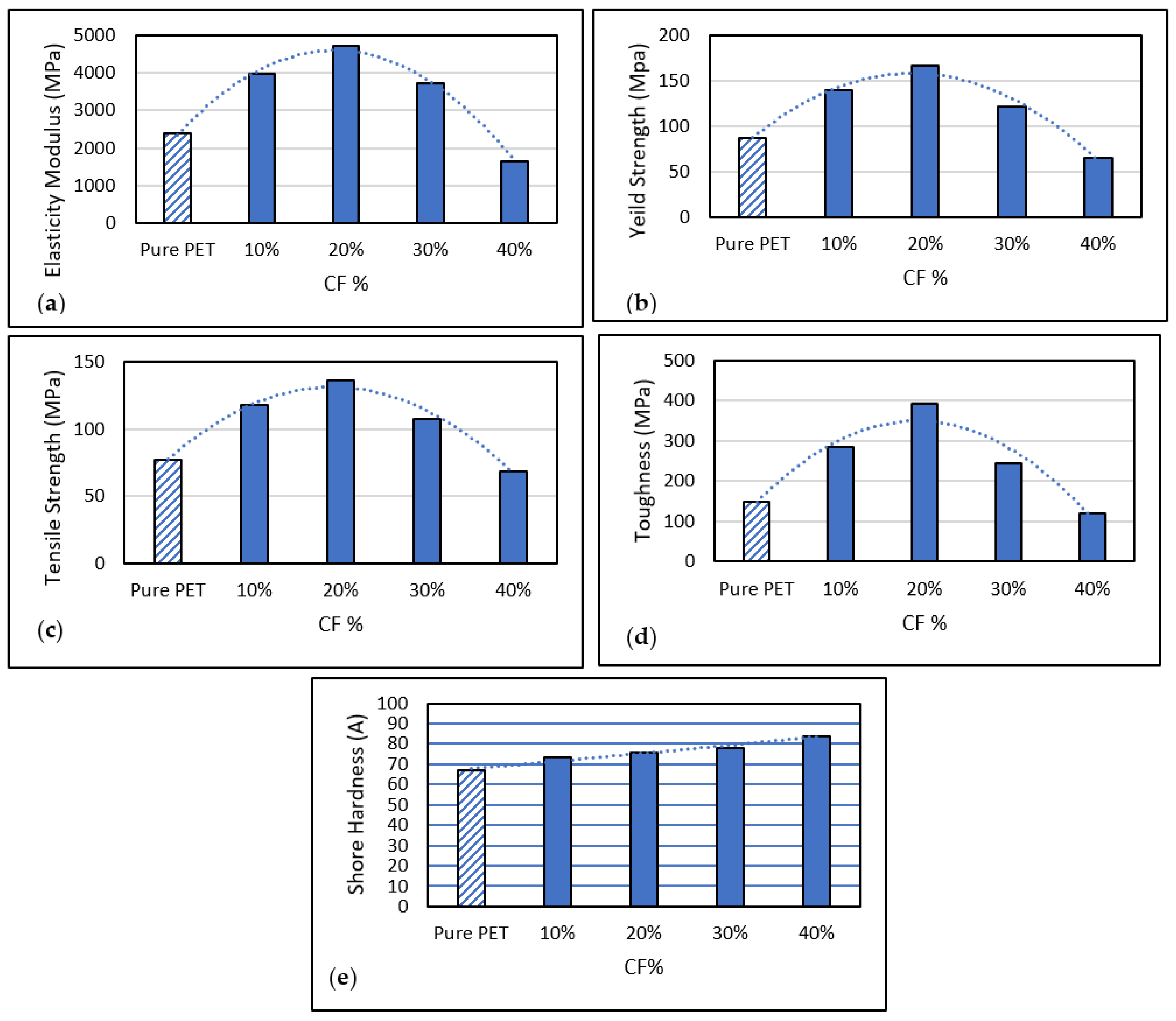
| Material ID | Elastic Modulus (GPa) | Yield Strength (GPa) | Tensile Strength (GPa) | Toughness (GPa) | Hardness (GPa) |
|---|---|---|---|---|---|
| Pure PET | 2389.9 | 87.6 | 77.6 | 148.2 | 66.9 |
| CFRP 10% | 3970.0 | 140.0 | 118.0 | 285.0 | 73.2 |
| CFRP 20% | 4719.3 | 166.7 | 136.8 | 390.6 | 75.6 |
| CFRP 30% | 3730.0 | 121.3 | 108.0 | 245.0 | 78.2 |
| CFRP 40% | 1650.0 | 65.0 | 69.0 | 118.0 | 83.8 |
| Pure Recycled PET | 20% CF Composite |
|---|---|
 |  |
 |
Disclaimer/Publisher’s Note: The statements, opinions and data contained in all publications are solely those of the individual author(s) and contributor(s) and not of MDPI and/or the editor(s). MDPI and/or the editor(s) disclaim responsibility for any injury to people or property resulting from any ideas, methods, instructions or products referred to in the content. |
© 2023 by the authors. Licensee MDPI, Basel, Switzerland. This article is an open access article distributed under the terms and conditions of the Creative Commons Attribution (CC BY) license (https://creativecommons.org/licenses/by/4.0/).
Share and Cite
Almahri, G.; Madi, K.; Alkaabi, F.; Badran, Y.; Shehadeh, K.; ElHassan, A.; Ahmed, W.; Alzahmi, S. Characterization of Hybrid FRP Composite Produced from Recycled PET and CFRP. Polymers 2023, 15, 2946. https://0-doi-org.brum.beds.ac.uk/10.3390/polym15132946
Almahri G, Madi K, Alkaabi F, Badran Y, Shehadeh K, ElHassan A, Ahmed W, Alzahmi S. Characterization of Hybrid FRP Composite Produced from Recycled PET and CFRP. Polymers. 2023; 15(13):2946. https://0-doi-org.brum.beds.ac.uk/10.3390/polym15132946
Chicago/Turabian StyleAlmahri, Ghdayra, Kaouthar Madi, Fatima Alkaabi, Yahia Badran, Khaled Shehadeh, Amged ElHassan, Waleed Ahmed, and Salem Alzahmi. 2023. "Characterization of Hybrid FRP Composite Produced from Recycled PET and CFRP" Polymers 15, no. 13: 2946. https://0-doi-org.brum.beds.ac.uk/10.3390/polym15132946