
Influence of Electrospinning Parameters on Fiber Diameter and Mechanical Properties of Poly(3-Hydroxybutyrate) (PHB) and Polyanilines (PANI) Blends


Abstract
:
1. Introduction
2. Materials and Methods
2.1. Materials
2.1.1. Sample Preparation
2.1.2. Electrospinning Equipment
2.2. Sample Characterization
2.2.1. Thermal Analysis
2.2.2. Wide Angle X-ray Diffraction (WAXD)
2.2.3. FT-IR Spectroscopy
2.2.4. Scanning Electron Microscopy (SEM)
2.2.5. Mechanical Properties
3. Results and Discussion
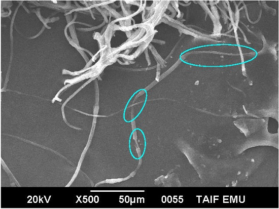
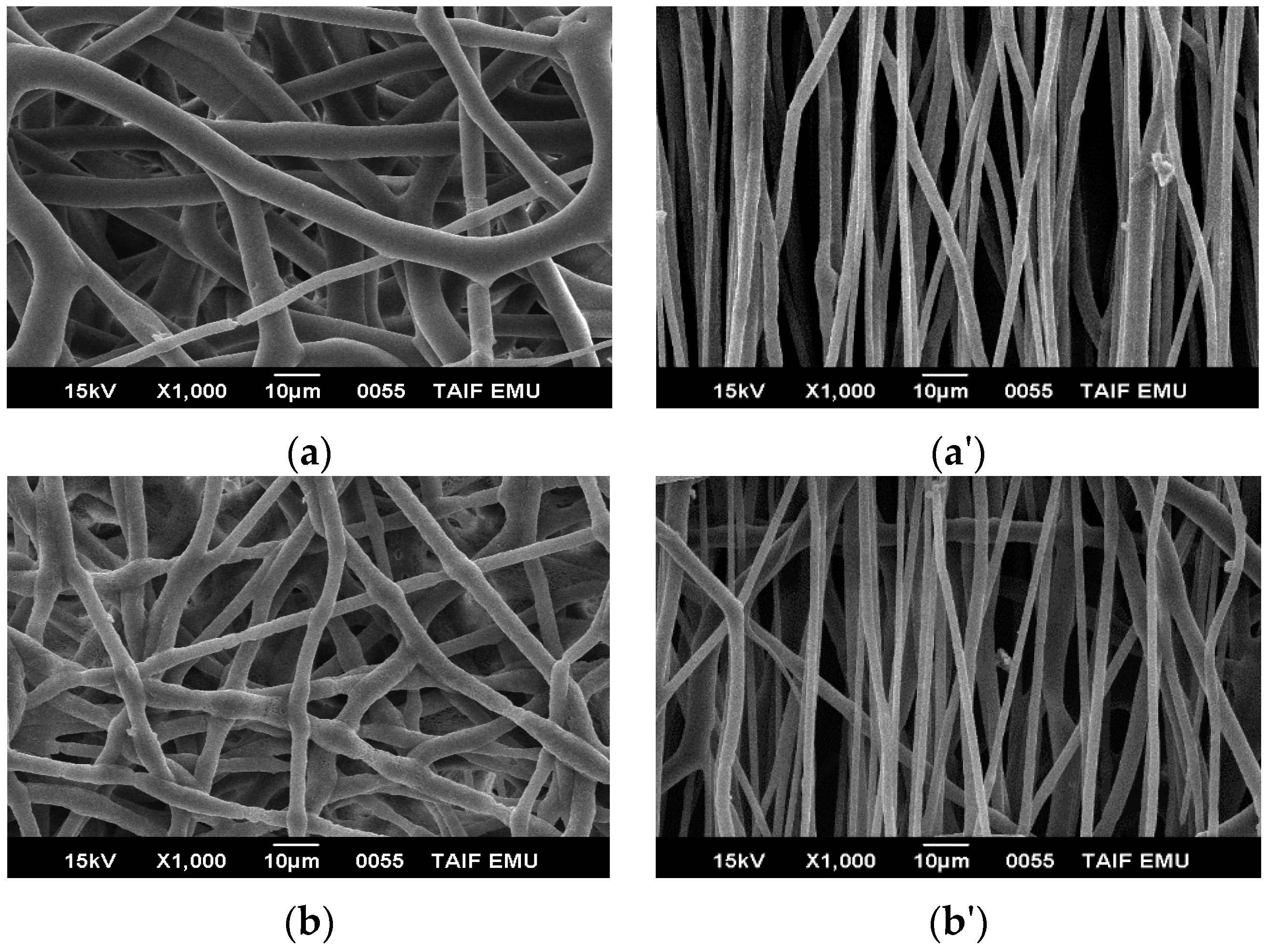
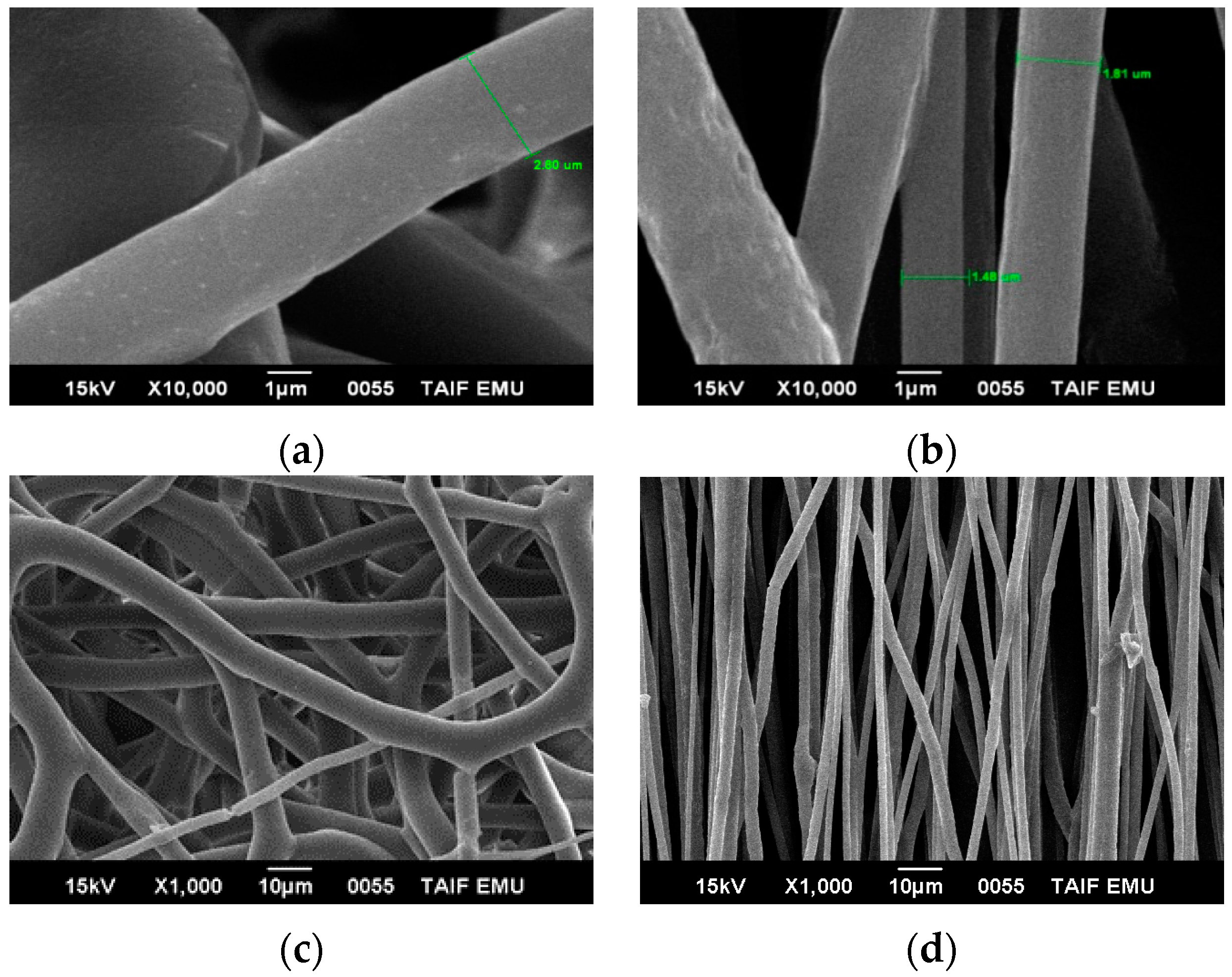
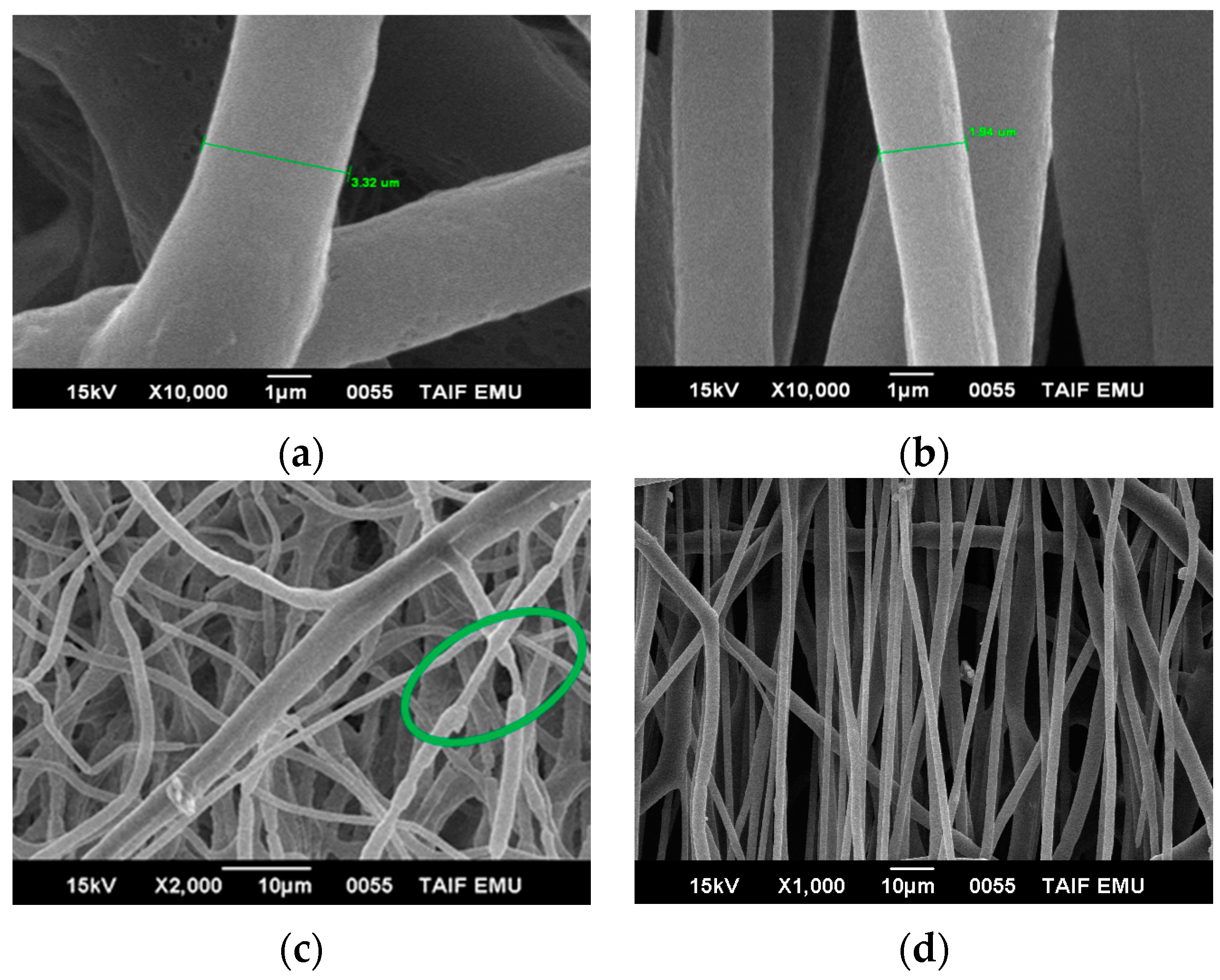
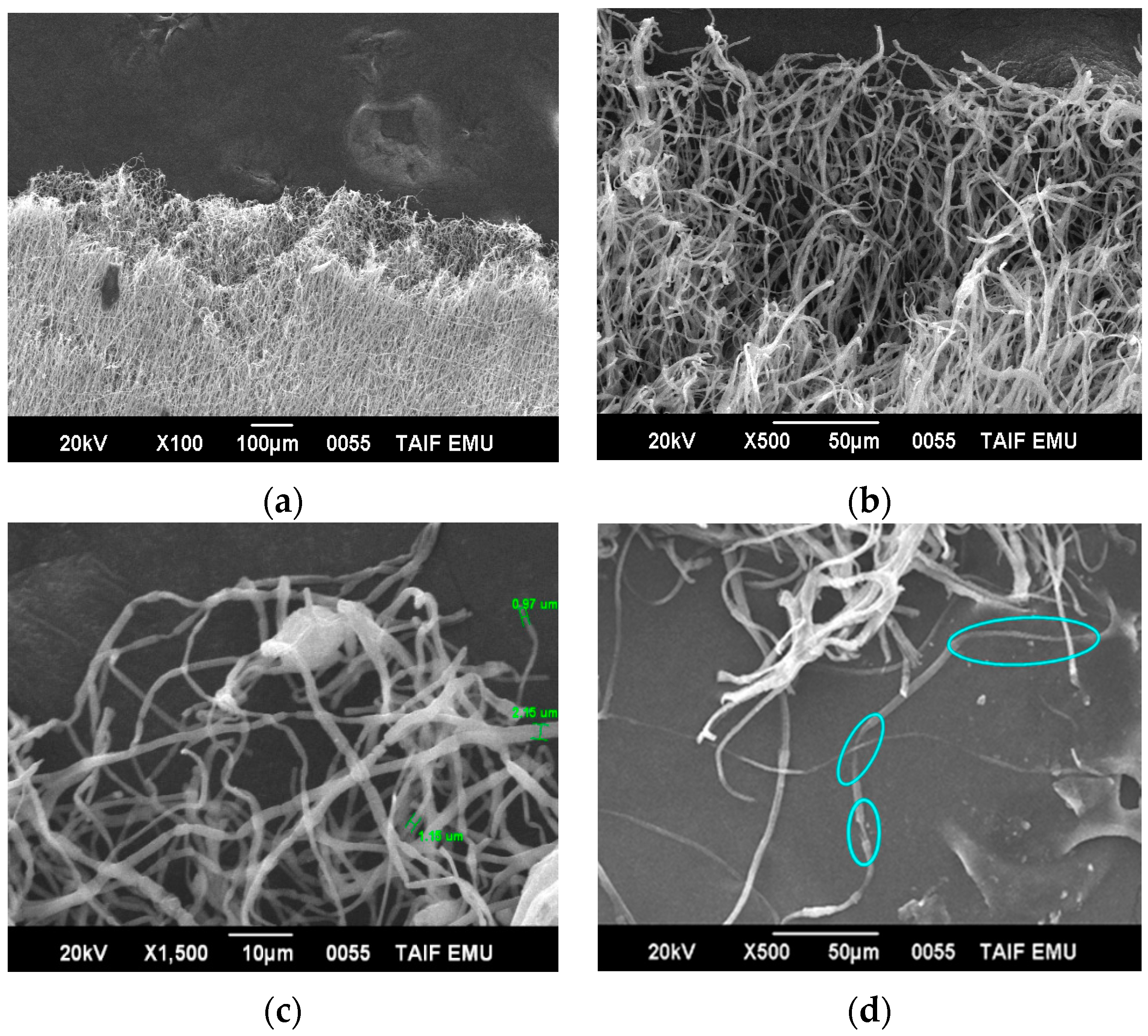
3.1. Fiber Morphology by Scanning Electron Microscopy (SEM)
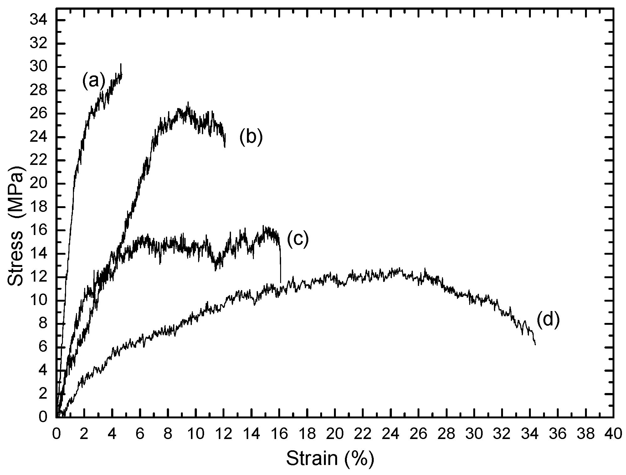
3.2. Mechanical Properties
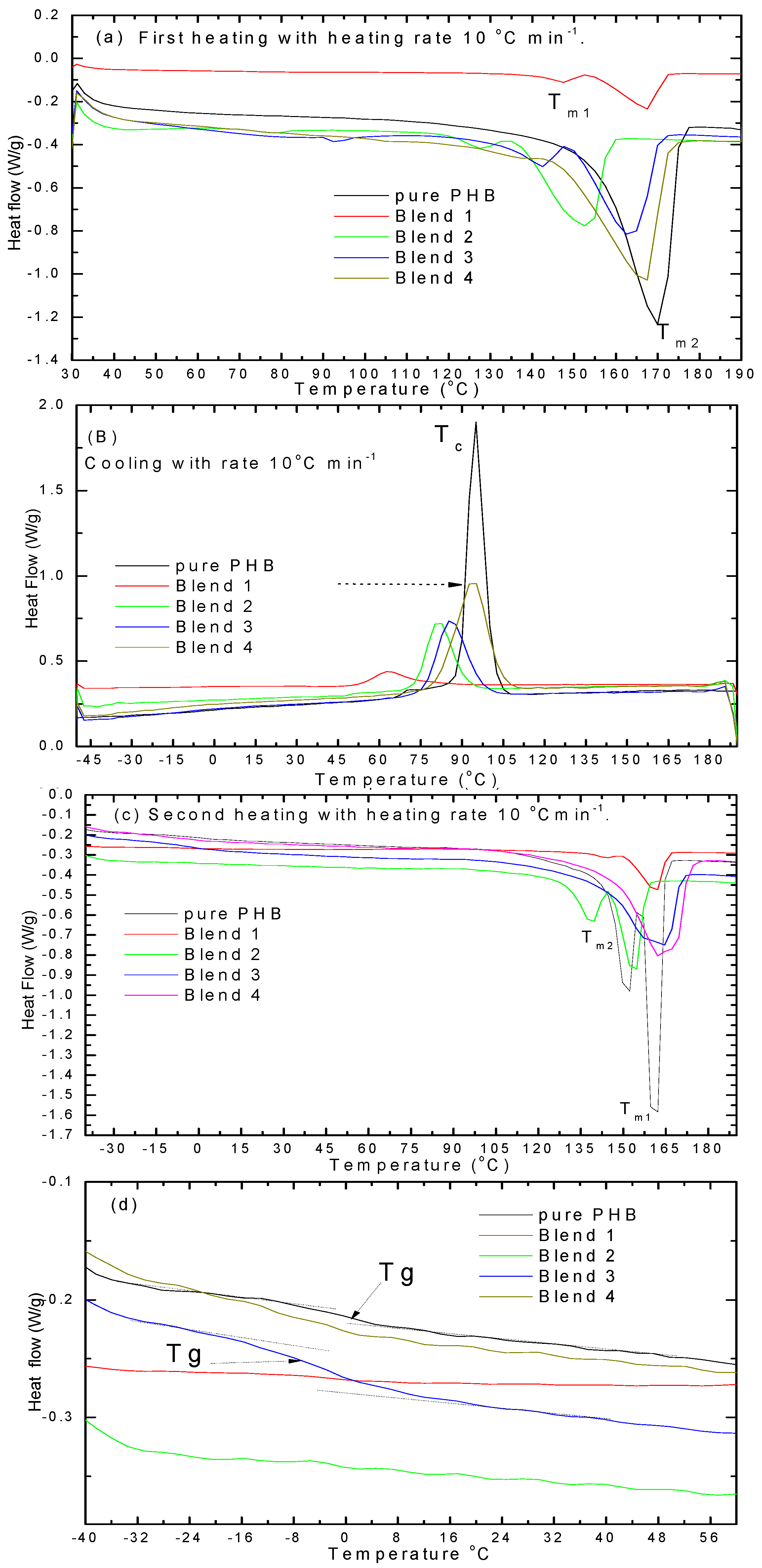
3.3. Thermal Analysis (DSC)
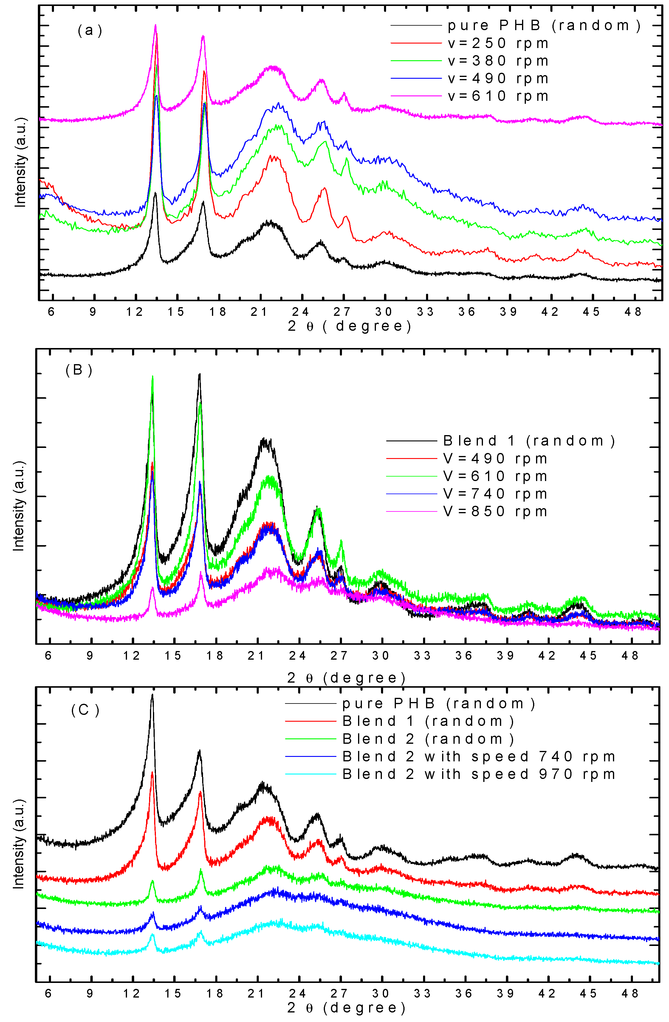
3.4. WAXD Analysis
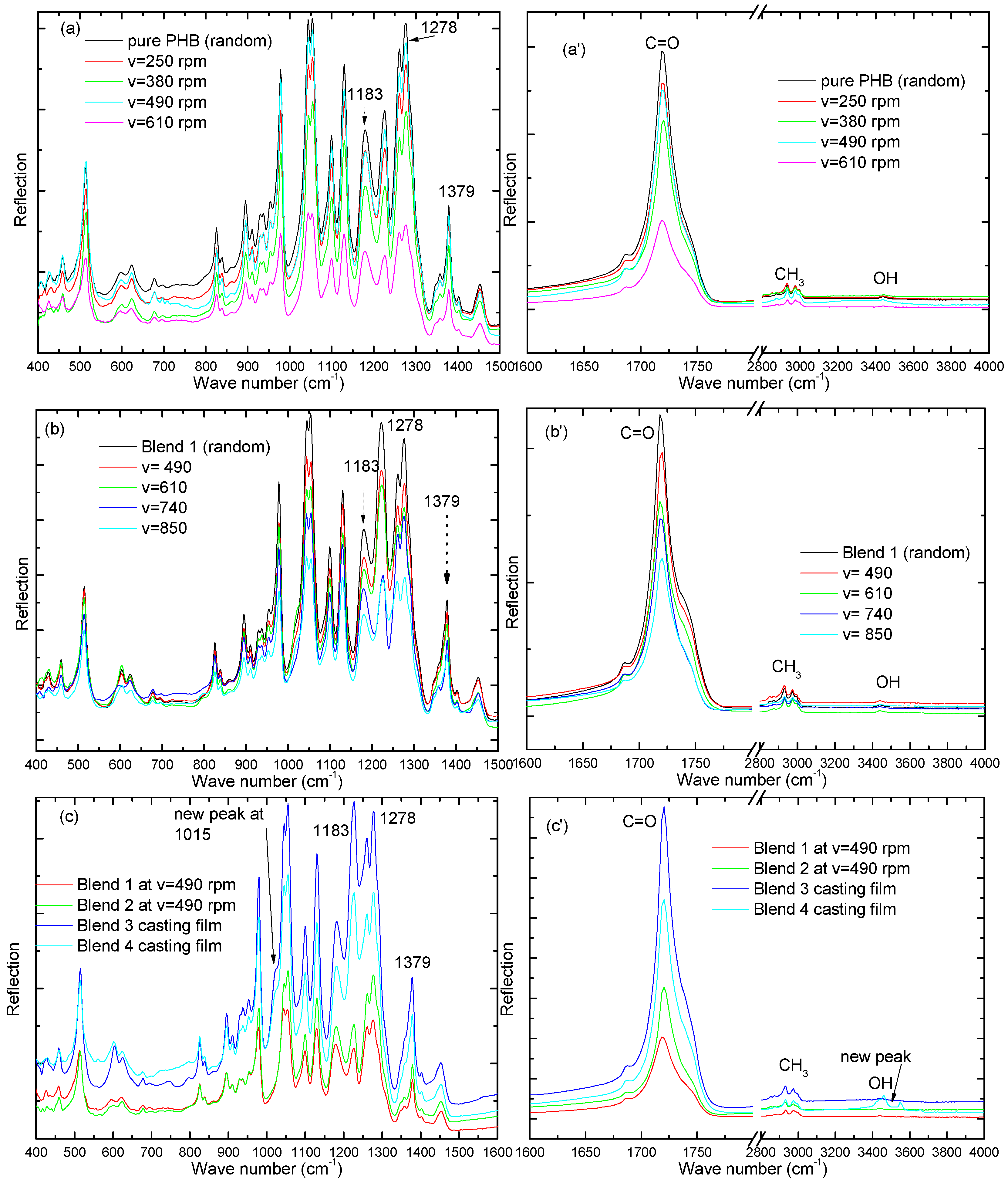
3.5. FT-IR Analysis
4. Conclusions
Supplementary Materials
Acknowledgment
Author Contributions
Conflicts of Interest
References
- Lee, Y.-S.; Arinzeh, L.T. Electrospun nanofibrous materials for neural tissue engineering. Polymers 2011, 3, 413–426. [Google Scholar] [CrossRef]
- El-Hadi, A.; Schnabel, R.; Straube, E.; Mueller, G.; Riemschneider, M. Effect of melt processing on crystallization behavior and rheology of poly(3-hydroxybutyrate) (PHB) and its blends. Macromol. Mater. Eng. 2002, 278, 363–372. [Google Scholar] [CrossRef]
- El-Hadi, A.; Schnabel, R.; Straube, E.; Muller, G.; Henning, S. Correlation between degree of crystallinity, morphology, glass temperature, mechanical properties and biodegradation of poly(3-hydroxyalkanoate) PHAs and their blends. Polymer Testing 2002, 21, 665–674. [Google Scholar] [CrossRef]
- Kulkarni, S.O.; Kanekar, P.P.; Jog, J.P.; Patil, P.A.; Nilegaonkar, S.S.; Sarnaik, S.S.; Kshirsagar, P.R. Characterisation of copolymer, poly(hydroxybutyrate-co-hydroxyvalerate) (PHB-co-PHV) produced by Halomonas campisalis (MCM B-1027), its biodegradability and potential application. Biores. Technol. 2011, 102, 6625–6628. [Google Scholar] [CrossRef] [PubMed]
- Agarwal, S.; Wendorff, J.H.; Greiner, A. Use of electrospinning technique for biomedical applications. Polymer 2008, 49, 5603–5621. [Google Scholar] [CrossRef]
- Hosseini, S.; Azari, P.; Farahmand, E.; Gan, S.N.; Hussin, A.R.; Yusof, R. Polymethacrylate coated electrospun PHB fibers: An exquisite outlook for fabrication of paper-based biosensors. Biosens. Bioelectron. 2015, 69, 257–264. [Google Scholar] [CrossRef] [PubMed]
- Zhang, S.; Prabhakaran, M.P.; Qin, X.; Ramakrishna, S. Poly-3-hydroxybutyrate-co-3-hydroxyvalerate containing scaffolds and their integration with osteoblasts as a model for bone tissue engineering. J. Biomater. Appl. 2015, 29, 139–146. [Google Scholar] [CrossRef] [PubMed]
- Deitzel, J.M.; Kleinmeyer, J.; Harris, D.; BeckTan, N.C. The effect of processing variables on the morphology of electrospun nanofibers and textiles. Polymer 2002, 42, 261–272. [Google Scholar] [CrossRef]
- Li, X.; Loh, X.J.; Wang, K.; He, C.B.; Li, J. Poly(ester urethane) consisting of poly[(R)-3-hydroxybutyrate] and poly(ethylene glycol) as candidate biomaterials: Characterization and mechanical property study. Biomacromolecules 2005, 6, 2740–2747. [Google Scholar] [CrossRef] [PubMed]
- Li, X.; Liu, K.L.; Wang, M.; Wong, S.Y.; Tjiu, W.C.; He, C.B.; Goh, S.H.; Li, J. Improving hydrophilicity, mechanical properties and biocompatibility of poly[(R)-3-hydroxybutyrate-co-(R)-3-hydroxyvalerate] through blending with poly[(R)-3-hydroxybutyrate]-alt-poly(ethylene oxide). Acta Biomater. 2009, 5, 2002–2014. [Google Scholar] [CrossRef] [PubMed]
- Benaniba, M.T.; Massardier-Nageotte, V. Evaluation effects of biobased plasticizer on the thermal, mechanical, dynamical mechanical properties, and permanence of plasticized PVC. J Appl. Polym. Sci. 2010, 118, 3499–3508. [Google Scholar] [CrossRef]
- Tan, S.M.; Ismail, J.; Kummerlowe, C.; Kammer, H.W. Crystallization and melting behavior of blends comprising poly(3-hydroxy butyrate-co-3-hydroxy valerate) and poly(ethylene oxide). J. Appl. Polym. Sci. 2006, 101, 2776–2783. [Google Scholar] [CrossRef]
- Vieira, M.G.A.; Silva, M.A.; Santos, L.O.; Beppu, M.M. Natural-based plasticizers and biopolymer films. Eur. Polym. J. 2011, 47, 254–263. [Google Scholar] [CrossRef]
- El-Hadi, A.M. Development of novel biopolymer blends based on poly(l-lactic acid), poly((R)-3-hydroxybutyrate), and plasticizer. Polym. Eng. Sci. 2014, 54, 1394–1402. [Google Scholar] [CrossRef]
- Imre, B.; Pukánszky, B. Compatibilization in bio-based and biodegradable polymer blends. Eur. Polym. J. 2013, 49, 1215–1233. [Google Scholar] [CrossRef]
- Pachekoski, W.M.; Agnelli, J.A.M.; Belem, L.P. Thermal, mechanical and morphological properties of poly(hydroxybutyrate) and polypropylene blends after processing. Mater. Res. 2009, 12, 159–164. [Google Scholar] [CrossRef]
- El-Hadi, A.M. The effect of additives interaction on the miscibility and crystal structure of two immiscible biodegradable polymers. Polímeros 2014, 24, 9–16. [Google Scholar] [CrossRef]
- Mekonnen, T.; Mussone, P.; Khalil, H.; Bressler, D. Progress in bio-based plastics and plasticizing Modifications. J. Mater. Chem. A 2013, 1, 13379–13398. [Google Scholar] [CrossRef]
- You, J.W.; Chiua, H.J.; Don, T.M. Spherulitic morphology and crystallization kinetics of melt-miscible blends of poly(3-hydroxybutyrate) with low molecular weight poly(ethylene oxide). Polymer 2003, 44, 4355–4362. [Google Scholar] [CrossRef]
- Kaito, A. Unique orientation textures formed in miscible blends of poly(vinylidene fluoride) and poly((R)-3-hydroxybutyrate). Polymer 2006, 47, 3548–3556. [Google Scholar] [CrossRef]
- El-Hadi, A.M.; Mohan, S.D.; Davis, F.J.; Mitchell, G.R. Enhancing the crystallization and orientation of electrospinning poly(lactic acid) (PLLA) by combining with additives. J. Polym. Res. 2014, 21, 1–12. [Google Scholar] [CrossRef]
- Subramanian, A.; Maheswari, U.K.; Sethuraman, S. Development of biomaterial scaffold for nerve tissue engineering: Biomaterial mediated neural regeneration. J. Biomed. Sci. 2009, 16, 108–119. [Google Scholar] [CrossRef] [PubMed]


© 2016 by the authors. Licensee MDPI, Basel, Switzerland. This article is an open access article distributed under the terms and conditions of the Creative Commons by Attribution (CC-BY) license ( http://creativecommons.org/licenses/by/4.0/).
Share and Cite
El-hadi, A.M.; Al-Jabri, F.Y. Influence of Electrospinning Parameters on Fiber Diameter and Mechanical Properties of Poly(3-Hydroxybutyrate) (PHB) and Polyanilines (PANI) Blends. Polymers 2016, 8, 97. https://0-doi-org.brum.beds.ac.uk/10.3390/polym8030097
El-hadi AM, Al-Jabri FY. Influence of Electrospinning Parameters on Fiber Diameter and Mechanical Properties of Poly(3-Hydroxybutyrate) (PHB) and Polyanilines (PANI) Blends. Polymers. 2016; 8(3):97. https://0-doi-org.brum.beds.ac.uk/10.3390/polym8030097
Chicago/Turabian StyleEl-hadi, Ahmed M., and Fatma Y. Al-Jabri. 2016. "Influence of Electrospinning Parameters on Fiber Diameter and Mechanical Properties of Poly(3-Hydroxybutyrate) (PHB) and Polyanilines (PANI) Blends" Polymers 8, no. 3: 97. https://0-doi-org.brum.beds.ac.uk/10.3390/polym8030097