

Non-Conventional Reinforced EPS and Its Numerical Examination

Faculty of Mechanical Engineering and Informatics, Institute of Energy Engineering and Chemical Machinery, University of Miskolc, H-3515 Miskolc, Hungary
*
Author to whom correspondence should be addressed.
Processes 2023, 11(1), 12; https://doi.org/10.3390/pr11010012
Submission received: 13 October 2022
/
Revised: 19 November 2022
/
Accepted: 16 December 2022
/
Published: 21 December 2022
(This article belongs to the Special Issue Chemical Engineering and Technology)
Abstract
:In the last decades, the EPS (expanded polystyrene) and the XPS (extruded polystyrene) have become the most frequently used thermal insulation. Furthermore, the XPS has step resistant thermal insulation with higher strength. Nowadays in our current economic situation, the circular economy plays a significant role. That means we need to intend making a product that becomes waste as late as possible. Instead of a product, the goal is to return it to the economy as a basic material for a new product. Instead of generating waste, a new chance must be given by reusing it. Based on that consideration, our research work was in producing reinforced EPS material, which has the physical and thermal properties at least, as the XPS is much more expensive to produce. For reinforcement, materials have been chosen, in terms of its current life cycle, considered as product or waste. The first choice were plastic straws and cutleries that will be redrawn from the market. The next additives were renewable materials from agriculture like straws of wheat. It is essential for this research work to map the possible raw materials, i.e., EPS and XPS. The article collects the properties of the EPS and XPS and the related simulation methods that can be found in the literature.
1. Introduction
Both EPS (expanded) and XPS (extruded) are closed-cell rigid insulation material made from the same basic material, polystyrene resin. Both polystyrene foams have the same chemical composition, but their production method is different. EPS, expanded polystyrene foam, is a thermoplastic, cellular polystyrene hard foam thermal insulation material. It has low density, 10–30 kg/m3, and is easy to handle. XPS, extruded polystyrene foam, is a hard, closed-cell polystyrene foam made with an extrusion-foaming process. Only boards can be manufactured from XPS hard foam, blocks cannot be produced. Its body density is 25–50 kg/m3 and that is the reason why its technical characteristics are significantly better than those of expanded PS foam. The article aims to establish whether it is worthwhile to direct our research in such a direction as to provide EPS with properties—especially strength—that reach those of XPS foam according to the circular economy. Firstly, the information of the literature regarding EPS and XPS materials and their applications was mapped, as well as a summary of the related simulation tests and test methods which were prepared. Furthermore, some experiences with additives were shown.
In 2019, the European Union accepted the motion regarding the withdrawal of single-use plastics from the market. The plastic cutlery and straws—which were intended to be used to strengthen EPS during our research—are among these products. About 25 million tons of plastic waste is generated in Europe every year, of which only 30% is recycled. Plastic waste makes up 85% of beach waste. That is why the decree was created, that forbids to market single-use plastic products that can be replaced with other, easily available and affordable products [1].
The most common area of usage of the materials in focus is the construction industry, including thermal insulation. In accordance with the European Union Directive 2018/844, member states must strive to find a cost-effective balance between the decarbonization of energy supply and the reduction of final energy consumption. The goal is to achieve zero-energy buildings for newly built buildings but also during renovations [2,3].
A new research direction appeared in the last years which aims to develop insulation materials with bio or waste additives. Some of the researchers focused on locally available basic materials [4] like straw, wood, or even aerated slurry. The other possibilities were fibers like wheat straw or rice husk [5] which were chemically treated.
2. Mechanical Properties of Expanded and Extruded Polystyrene
One of the most important tasks for today’s construction industry is to create buildings that have a minimal negative impact on the environment and at the same time have the best possible energy efficiency. This is the reason why thermal insulation, its materials and process technology, came into view. The materials most commonly used for thermal insulation—naturally in addition to other types of materials—are EPS, XPS and mineral wool.
As mentioned in the Introduction, both EPS and XPS are polystyrene foam with the same chemical composition, but the big difference between them is the process by which they are produced.
2.1. EPS and Reinforced EPS
EPS materials are reliable insulating materials and provide a long-lasting internal and external protection for the walls of a building. Thanks to its closed cell structure, it provides excellent protection against moisture. Its density, strength and thickness determine its heat resistance and compressive load capacity (Table 1). It can also be used to insulate walls, ceilings, floors and roofs.
Examining the compressive strength of EPS, it can be established that the density of the foam affects its mechanical properties. Since EPS can be easily compressed, it is ideal for reducing the horizontal and vertical tension generated in its porous material, while the lateral displacement is almost negligible. The compressive strength depends to a large extent on the density of the material, the degree of material changes or deformation and the magnitude of the applied compressive force. When the tension is gradually increased, more EPS bubbles disappear, and a lower compressive strength is observed. An increase of EPS density results an increase of compressive strength. An increase of the value of the elasticity modulus (Young’s modulus) can be observed for higher density EPS and when the compressive stress increases. Therefore, it can be said that when the deformation rate increases, both the elasticity index and the compressive stress increase. The elasticity index is more affected by the rate of deformation in the case of EPS with a denser structure, while the strength of the whole sample at the point of elastic deformation is more sensitive to the rate of deformation in the case of EPS with a lower density, which is related to the damage of the bubbles. Table 1 shows the properties of EPS materials with four different densities [6].
In the European Union, about 40% of all energy consumption comes from the energy consumption of buildings, and on top of that, even 35% of the emitted CO2 is due to our outdated buildings. Flat roofs, as an element of the building’s stratification, play a large role in heat loss—of course, depending on the structure and height of the building. EPS sheets provide excellent thermal insulation and reduce heat loss in the insulation of flat roofs. EPS can be used not only in the form of sheets for this insulation purposes of a roof, but by mixing EPS granules with cement, creating lightweight concrete which also fulfils this thermal insulation task excellently [7].
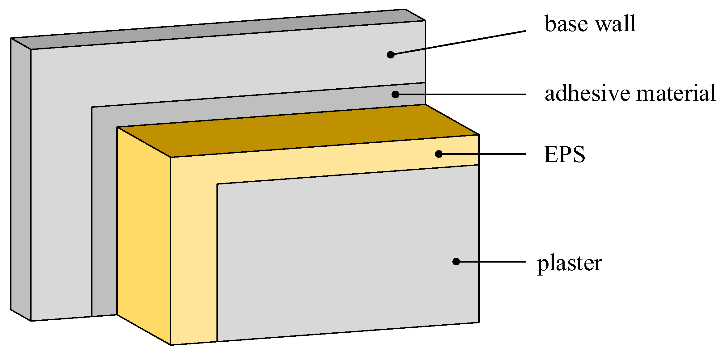
In relation to the insulation of buildings, not only thermal insulation regulations and needs must be taken into account, but also sound insulation. EU regulations encourage member states to also pay attention to sound insulation, as environmental noise pollution is a global problem. If EPS is combined with plaster of suitable thickness, significant results can be achieved [8]. Figure 1 shows such a combined structure.
If a 5 mm thick layer of plaster is applied to the EPS that is fixed to the base wall, a significant 8–16 dB increase in the sound insulation value can be achieved in the frequency range above 630 Hz. If the thickness of the plaster is further increased by another 5 mm—so the plaster layer is 10 mm—the soundproofing ability of EPS increases to 5 dB in the frequency range of 630–1000 Hz [6,8].
A study reports on the use of EPS related to the construction industry, in a slightly different way, in connection with road construction in Italy. Expanded polystyrene is a thermoplastic material that is made from pre-enriched polystyrene beads, so despite its extremely light weight, it has great strength and thermal insulation. Thanks to these properties, natural materials can be an alternative in architectural projects that would otherwise require a large budget or be time-consuming, or even impossible to carry out. In Italy, EPS has been successfully used for twenty years in the field of road infrastructure, specifically in the implementation of roads, bridge connections, light embankments and refills, but, above all, in the construction and repair of roads at risk—such as landslides and vibration [9].
2.2. XPS
The production of extruded polystyrene foam, i.e., XPS, starts from solid polystyrene crystals. These crystals are put into an extruder with various additives and foaming agents. Under controlled conditions in the extruder, this mixture attains its final, viscous liquid plastic state at high temperature and high pressure. This thick, hot melt is fed into a continuous press. When it comes out of the press, it swells into foam, acquires its final shape, then cools down and can be cut to size.
The structure of the XPS cell is completely closed and there are no cavities between the cells. This makes XPS resistant to pressure and moisture. Its structure is homogeneous and cannot be easily broken into pieces [10].
Extruded polystyrene foam has better thermal insulation properties than EPS, so one of its popular fields of application is soil insulation. In such an application, XPS is used more often than EPS not only because of its better thermal insulation properties, but also because of its better mechanical properties since these surfaces must also be load (step) resistant.
2.3. Comparison of EPS and XPS
In the previous sections, the properties of EPS and XPS were discussed separately. In this section, the two materials were compared based on different aspects. First of all, the structure of the two materials were presented: EPS is made from small polystyrene beads by steaming in a mold, where the beads swell and stick together, but there are gaps between them, which makes it easier to absorb water than XPS, which has a completely closed cell structure [9,11].
Table 2 summarizes some of the physical properties of EPS70 and XPS. In the construction industry, the R-value is widely used. This value shows the thermal resistance of a unit surface [10].
XPS has advantages over EPS, such as lower absorption capacity and better strength, but this is also reflected in the price of the two materials, since the price of XPS products is 50–80% higher than that of EPS products.
3. Examination Possibilities
The most common method for checking the conformity of a product or material is the application of measurements, however, nowadays, the finite element simulations are used more and more, since with this procedure, after the validation of the model, there is no need to prepare additional samples, and the conformity of a product can be determined under different loads. In the case of expanded polystyrene, the biggest challenge during the simulation is the correct specification of the material model since its properties depend on the rate of deformation and the density of the polymer foams. This means that the design of the material model depends to a large extent on the density of the foam and their area of application. After selecting the appropriate material model, experimental tests are necessary to determine the parameters.
3.1. Laboratory Measurement Required for Simulation
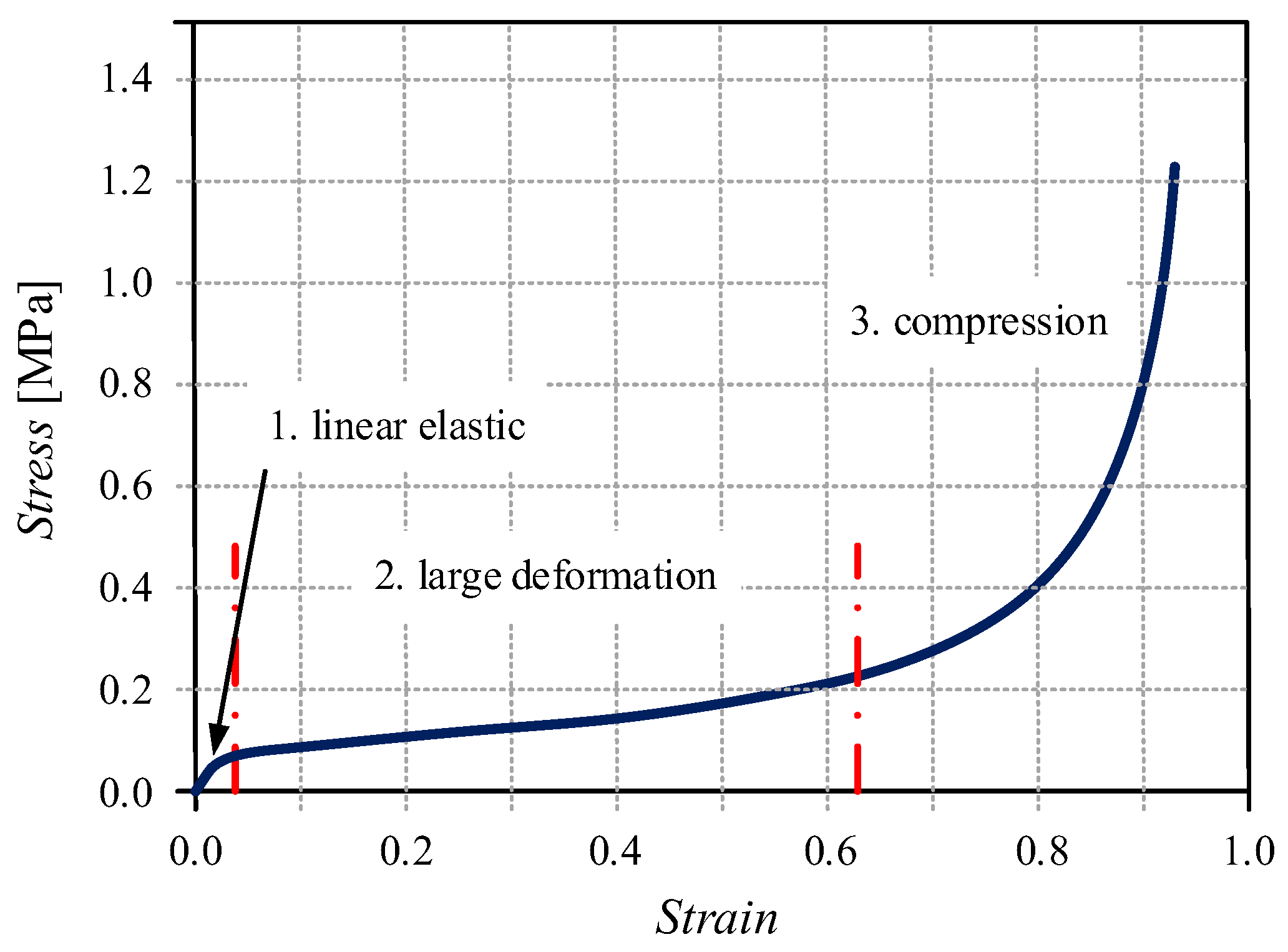
Figure 2 shows the stress-strain diagram of an EPS foam. It can be seen that the curve can be divided into three parts: the linearly elastic section, the large deformation section, where the stress value is almost constant with increasing deformation, and the compression section, where a rapid exponential increase of stress can be observed with small deformation. When a foam is compressed, the walls of the bubbles begin to bend, leading to a linear elastic deformation; beyond a critical deformation value, these bubbles collapse due to elastic buckling every time opposite bubble walls come into contact. As the balls close up, the structure begins to thicken, thereby increasing the stiffness of the material rapidly. To determine this curve, a compression test is required.
In the case of quasi-static testing, the most frequently used specimen design is cylindrical [12]. According to the study of Bertholf and Karnes [13], the tests showed that lateral and axial inertia and friction can create additional constraints, which results a multiaxial stress state, therefore the optimal ratio between the height and diameter of the cylinder is 0.5. In addition to the cylindrical design, cube and rectangular test specimens are also used [14,15].
Quasi-static compression tests are usually performed at several low strain rates. The elastic modulus can be determined from the stress-deformation diagram of the compression test. The Poisson factor—a very important parameter that is used for simulation settings—can be determined from the compressed specimen. No lateral elongation is observed during compression of EPS foams, so the Poisson’s factor is nearly zero. The volume of the material is not constant during the test, which means that the density of the test specimen increases [14,16]. Figure 2 shows the literature data alongside the quasi-static compression tests, tensile tests, impact tests and dynamic compression/tensile tests. For validation of the finite element simulation, the compression test is sufficient.
3.2. Finite Element Simulation of EPS
In the following, the settings and results used for these simulations are presented. One of the earliest technical articles deals with the simulation of 2D and 3D impact tests of XPS foams [16]. The cited authors executed the simulations in ABAQUS Standard version 6.2. The obtained results closely correlated to the data obtained during the experiments.
Gerhard Slik et al. [17] already performed an investigation of expanded polystyrene foam. In the case of the selected material, the rate of deformation did not significantly affect the results, so it was not considered during the simulation either. The simulations were made with the help of LS-DYNA software. In this software, it is possible to use several foam material models. The authors selected two material models: a highly compressible, low-density, elastic foam (Material Type 57) and a slightly elastic foam (Material Type 63). A small damping factor was applied. In the case of Material 57, when the load was removed, the material partly regained its original shape, while in the case of Material 63, the specimen remained in its deformed shape.
After the selection of the material model, three types of simulations were performed: impact test, dynamic head impact test and dynamic pelvis impact test. The importance of the latter two tests was that the deformation should not be unidirectional. The stress-strain diagram was determined from the simple impact test. As the second step, the experiment and simulation of the other two tests were executed to validate the material model. The results of the first and second tests were almost identical, however, in the case of the impact test hitting the head, further changes are required.
The study by Ozturk and Anlas [18] also deals with EPS foam, however, unlike the previous ones, multiple cases of loading and unloading were examined. In the case of energy-absorbing components, it is more important to determine the maximum displacement, force and deceleration under load for a given absorbed energy, than to determine the residual deformation, stress-strain diagram and energy release during unloading. The authors used LS-DYNA and ABAQUS software. In the case of ABAQUS, the application of the breakable foam material model with volume hardening gave a good solution and the selected material was EPS20. This material model uses an elliptic yield surface in the deviatoric stress and hydrostatic stress field, which requires two parameters: compression yield ratio, which is the initial yield strength in the case of uniaxial pressure and the ratio of the initial yield strength in the case of hydrostatic pressure. The hydrostatic yield strength ratio is the ratio of the tensile strength resulting from a hydrostatic tensile test to the initial yield strength resulting from a hydrostatic compression test. In addition, to calculate the hardening, the yield strength (σy) and the uniaxial plastic deformation (εplaxial) have to be determined. εplaxial can be determined from the nominal engineering strain:
where εnom is the nominal engineering strain (negative for pressure) and εel is the elastic deformation. The simulations performed with this model correctly determined the impact/collision factor (G) in the case of the first impact, however, in the case of multiple impacts, the software calculated higher values. During the simulations carried out with the LS DYNA software, the previous low-density foam material model (MAT57) was used, since in this case, the shape and hysteresis of the unloading, reloading and displacement curves can be controlled with the help of two parameters. In this case, nominal stress and strain data from a single load test are required. The basic model itself was not well-suited to the examination of components exposed to multiple loads, however, by calibrating the hysteresis and shape factor of the MAT57 material, the simulations accurately predicted the value of the impact factor both in the case of small and large increases in G.
Thus, it can be said that in the case of the LS-DYNA material model, the calibration procedure developed by the authors can also be used for other foams.
Based on the work of Ozturk and Anlas, Shah and Topa [16] also used the same material model during their quasi-static tests with the LS-DYNA software. The following parameters are necessary: the density of the material, modulus of elasticity, Poisson’s factor, stress-strain curve, tensile stress and damping factor. In addition, impact tests were also carried out, in which case the previous material model was not well applicable, since the compressive force affects only a small part of the foam, so in addition to the compressive force, a shearing force is also generated, therefore additional additions were added to the model:
- Material destruction (by modifying the MAT_ADD_EROSION command) to simulate the brittle destruction of the foam.
- Further development of the material model to avoid the negative volume error (exponential extension of the stress-strain curve).
- Application of internal contact.
The results of the simulation correlate well with the results of the measurements, therefore, the model developments are suitable for the precise determination of stresses and deformations arising in the case of combined loads.
Krundaeva et al. [15] worked on determining the dynamic compressive strength of EPS foam, for which they applied a material model improved by Shah and Topa. The simulations were performed with the help of LS-DYNA software, where, in addition to the variation of the deformation rate, the density and temperatures were also changed. The results showed that temperature affects the strength of EPS, a decrease was observed at high temperature (50 °C) and an increase at low temperature (−20 °C). The applied parameters to the material model were able to accurately predict the load and deformation of the EPS foam.
4. Experiences of EPS with New Type of Additives
The goal of this research is using waste as a material. Polystyrene particles are used as raw material. The expanded polystyrene (EPS) is widely used in the construction industry for thermal insulation of facades as it was mentioned earlier. The biggest disadvantage of the insulating element made of EPS material is that the material can undergo permanent deformation due to mechanical stress. There is such an insulating element that is produced by a different technology (XPS—extruded polystyrene), but its price is significantly higher [19,20].
The aim of this research is to develop an EPS-based product, which has almost the same mechanical properties as XPS. During the research, it was necessary to work on the manufacturing technology of the sample, the test method of the sample, and to further develop the sample, it was necessary to prepare mechanical (FEM) and numerical thermodynamic simulations (CFD) [21].
4.1. Technology of Producing Simple Pieces
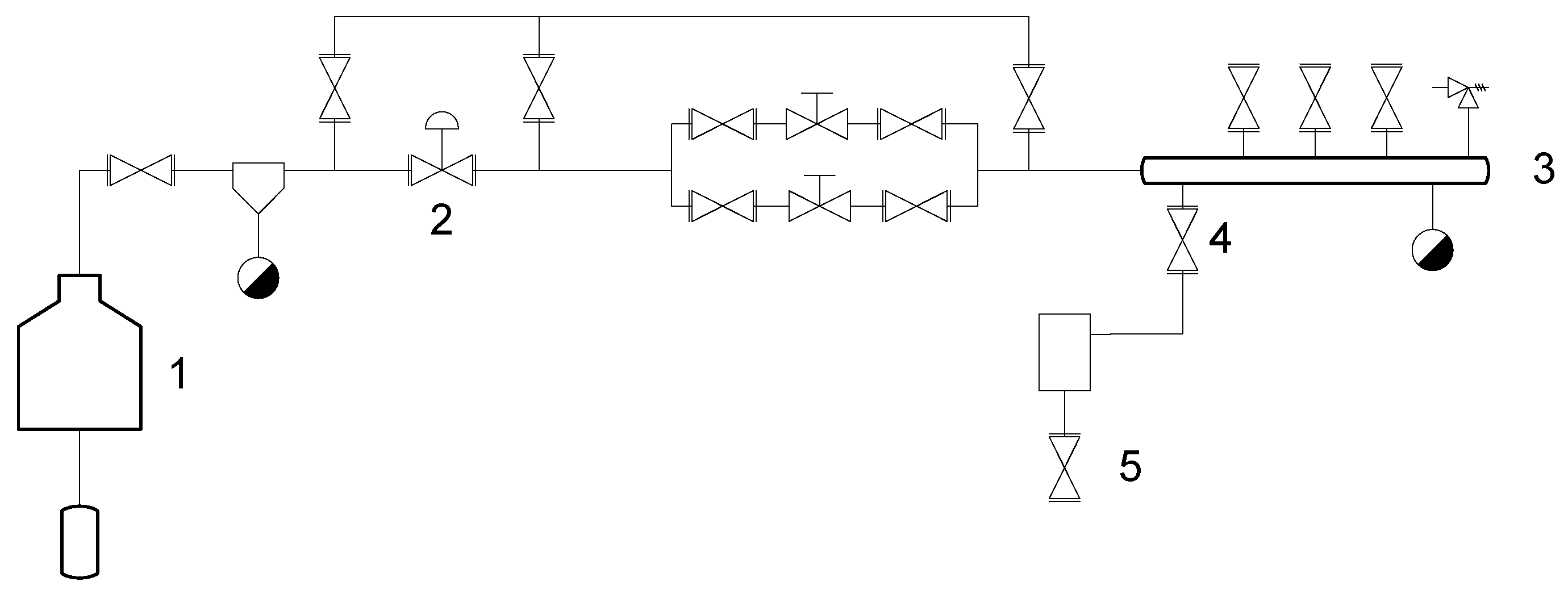
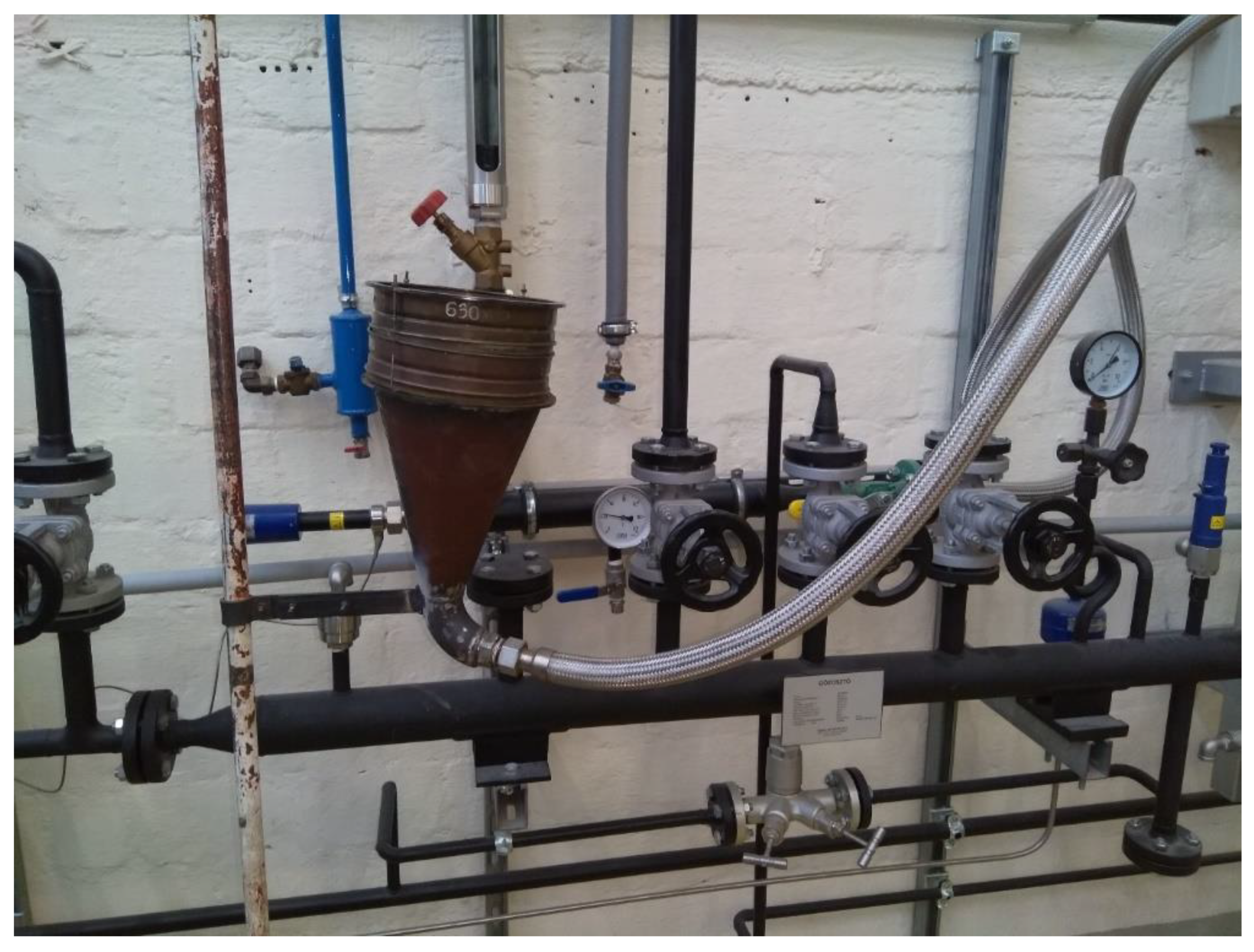
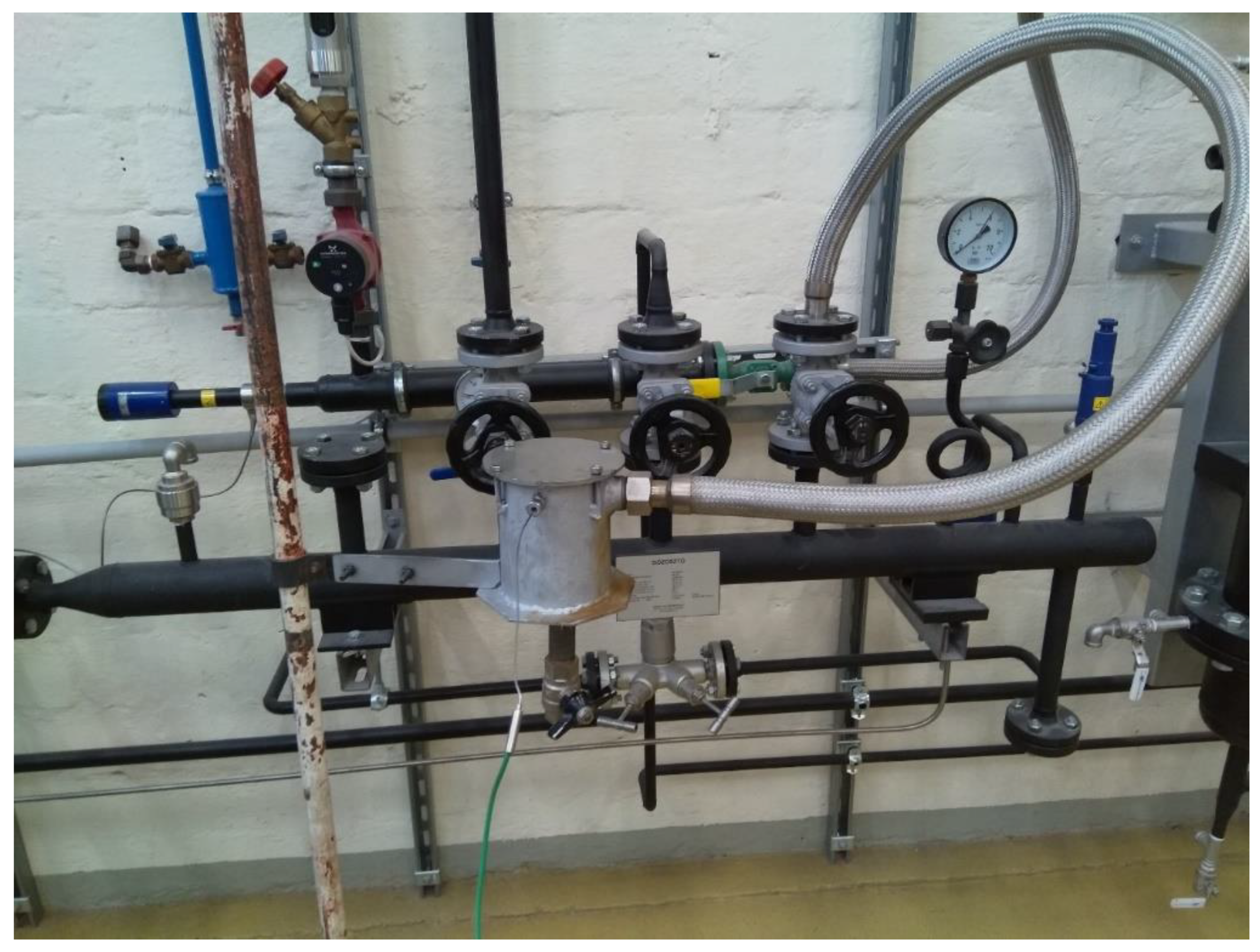
The production of the EPS samples begins with the pre-foaming of small polystyrene particles so the size of the particles can be increased by 20–50 times due to the pentane in the small particles under the influence of steam. It is important that the pressure of the steam must be 1 bara, which means saturated water steam at around 100 °C. The “heat treatment” lasts approximately 15–20 min. The balls of increased particle size are filled into the shaping vessel, which is blown through with steam at 115–120 °C. Figure 3 shows the pdf of the designed steam system.
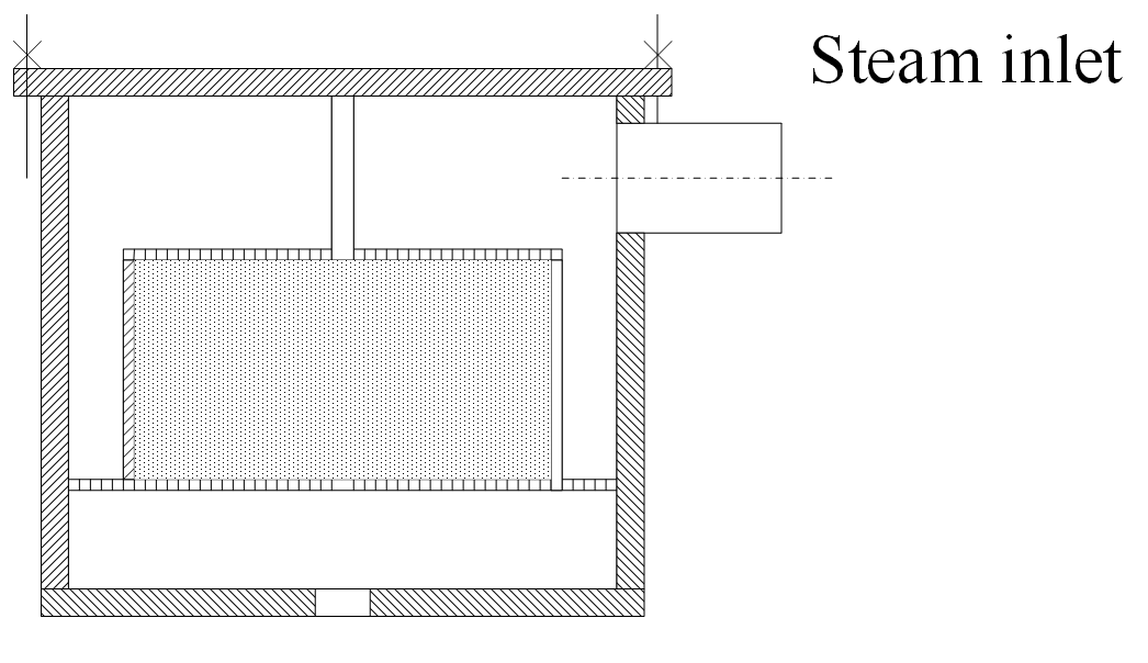
For the production, the Certuss electric steam generator—number 1—was used, which produces a maximum of 10 barg of saturated water steam. It was necessary to reduce this to the desired pressure with a pneumatic control valve number 2. During production, this was around 2 barg. The mass flow of steam was further reduced with the valves located on steam header (number 3). By opening valve number 4, steam is introduced into the molding chamber as shown in Figure 4.
By throttling the valve located at the lower point of the forming chamber, the temperature can be controlled in the chamber depending on the tension of the steam.
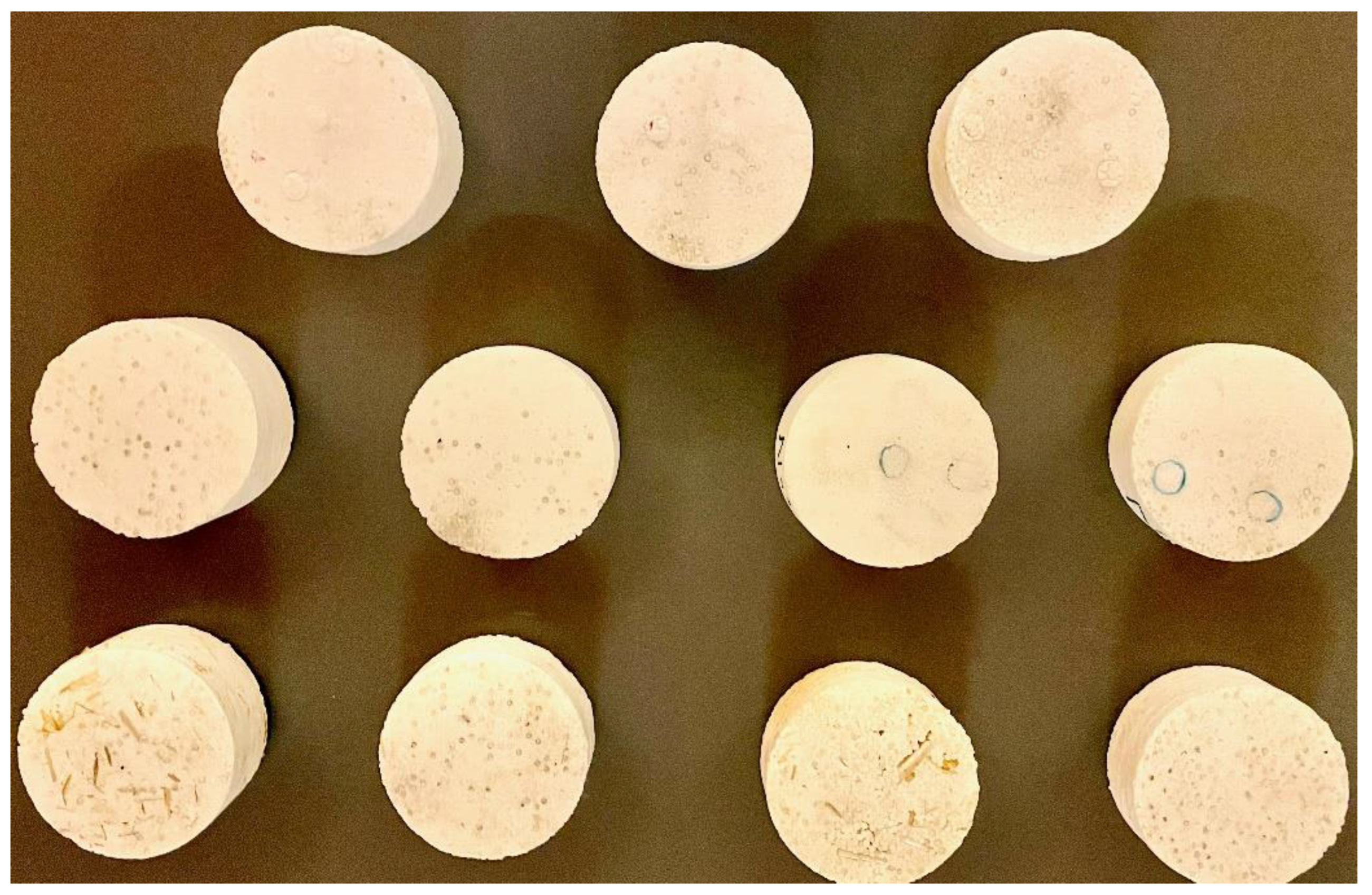
During the production of the sample, we made both unreinforced and waste-reinforced test specimens. The production technology was the same in both cases.
When choosing the waste material, it was important to have a favorable influence on the mechanical properties so that the thermal properties do not deteriorate significantly. Wheat and plastic straws were chosen as waste material at the beginning of the experiments. During the tests and production, we encountered several difficulties, because if a too large proportion of waste was used, the polystyrene particles could not stick to each other, so a product suitable for further testing could not be produced. In the case of a smaller amount of waste, during the examination of the product, the conclusion is that the strength properties of the final product fall short of the original product.
Next, the use of plastic waste was examined. Cylindrical tubes made of LDPE material were placed in the sample, the inner part of which was also filled with polystyrene balls.
4.2. Mechanical Test
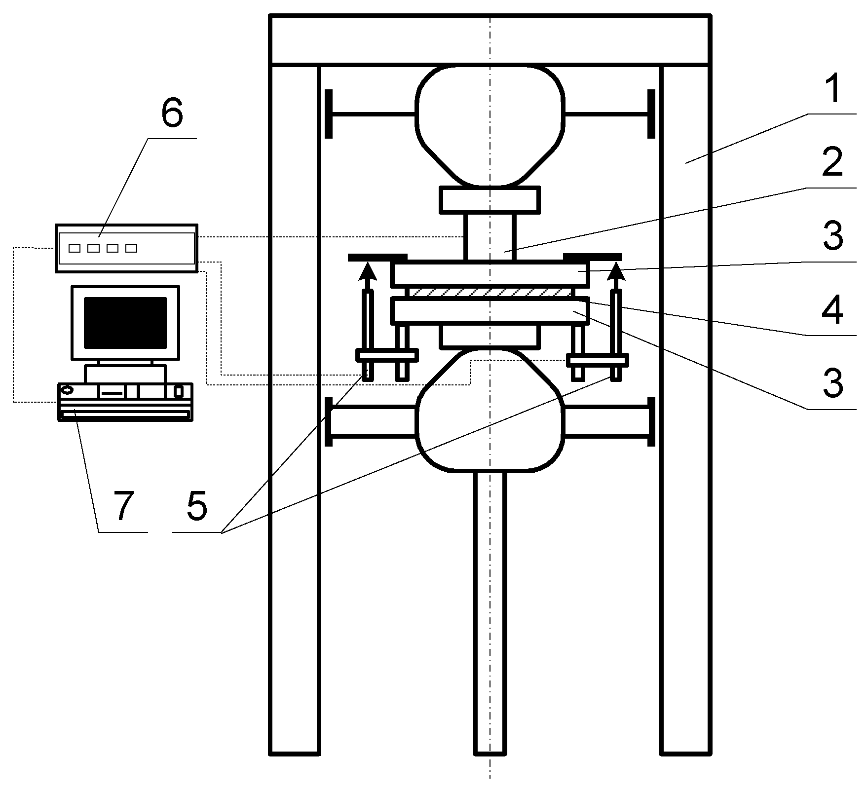
A pressing machine (Figure 8) was used for the mechanical testing of the foamed raw materials. With the help of the pressing machine, we created a surface load on both sides of the raw material and examined the deformation of the tested material as a function of the load.
During the measurement, the used force and the compression of the sample piece were recorded with a frequency of 1 Hz. From the displacement-force diagram, it is possible to draw conclusions regarding the compressive stress and specific strain arising in the material.
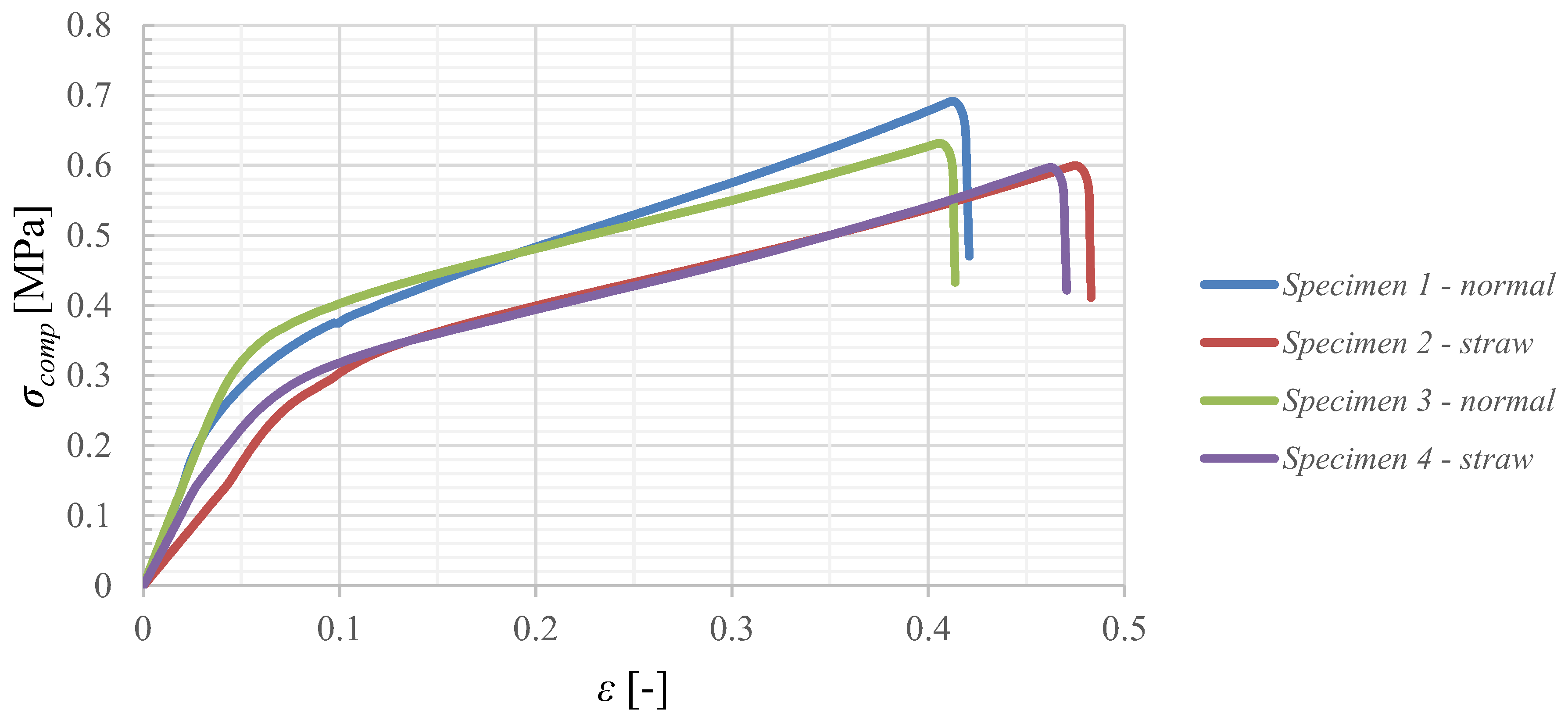
The specific displacement-stress diagrams recorded during the measurement are illustrated in the figures below.
It is clear from Figure 9 that the compressive strength of the polystyrene specimens reinforced with straw is lower than the values of the unreinforced specimens.
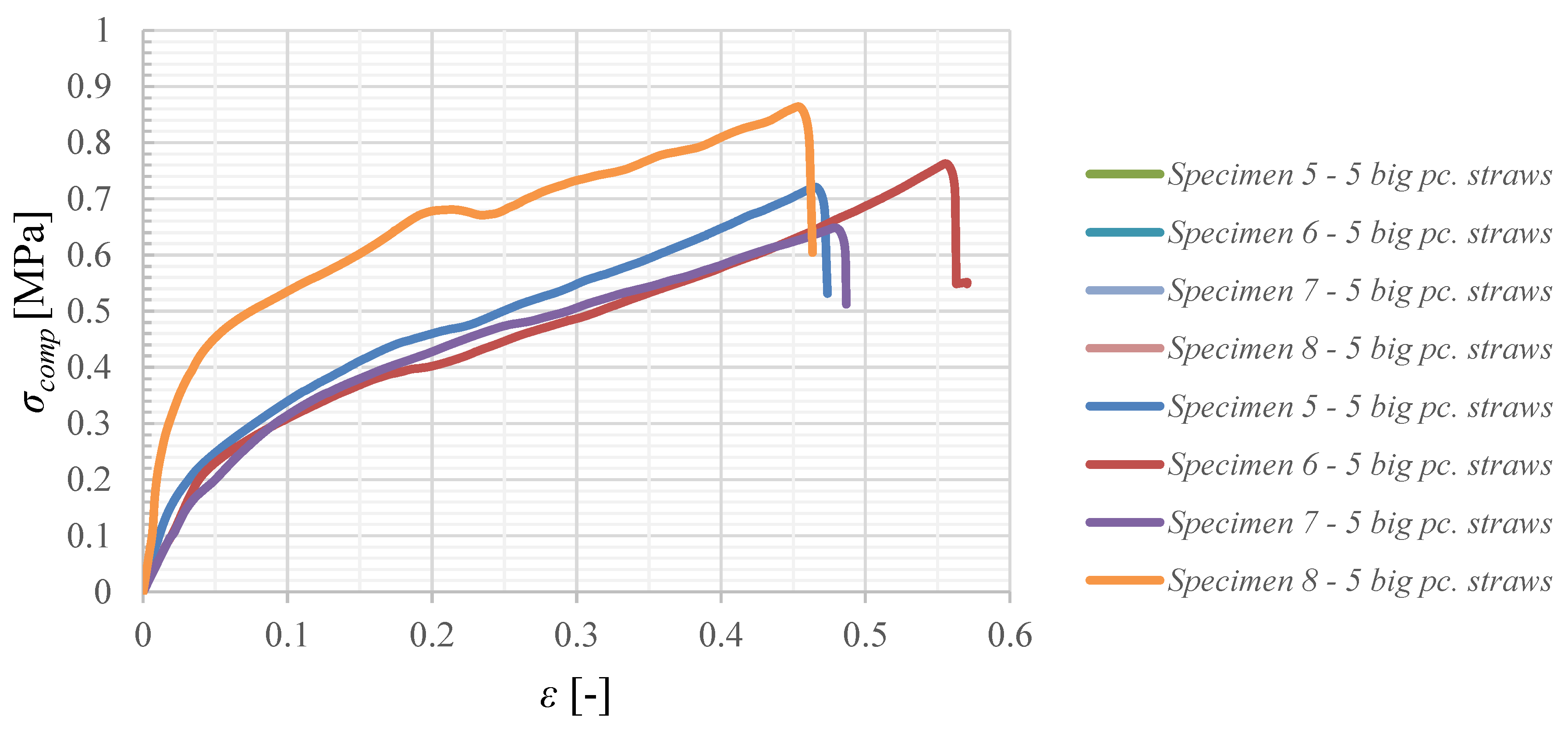
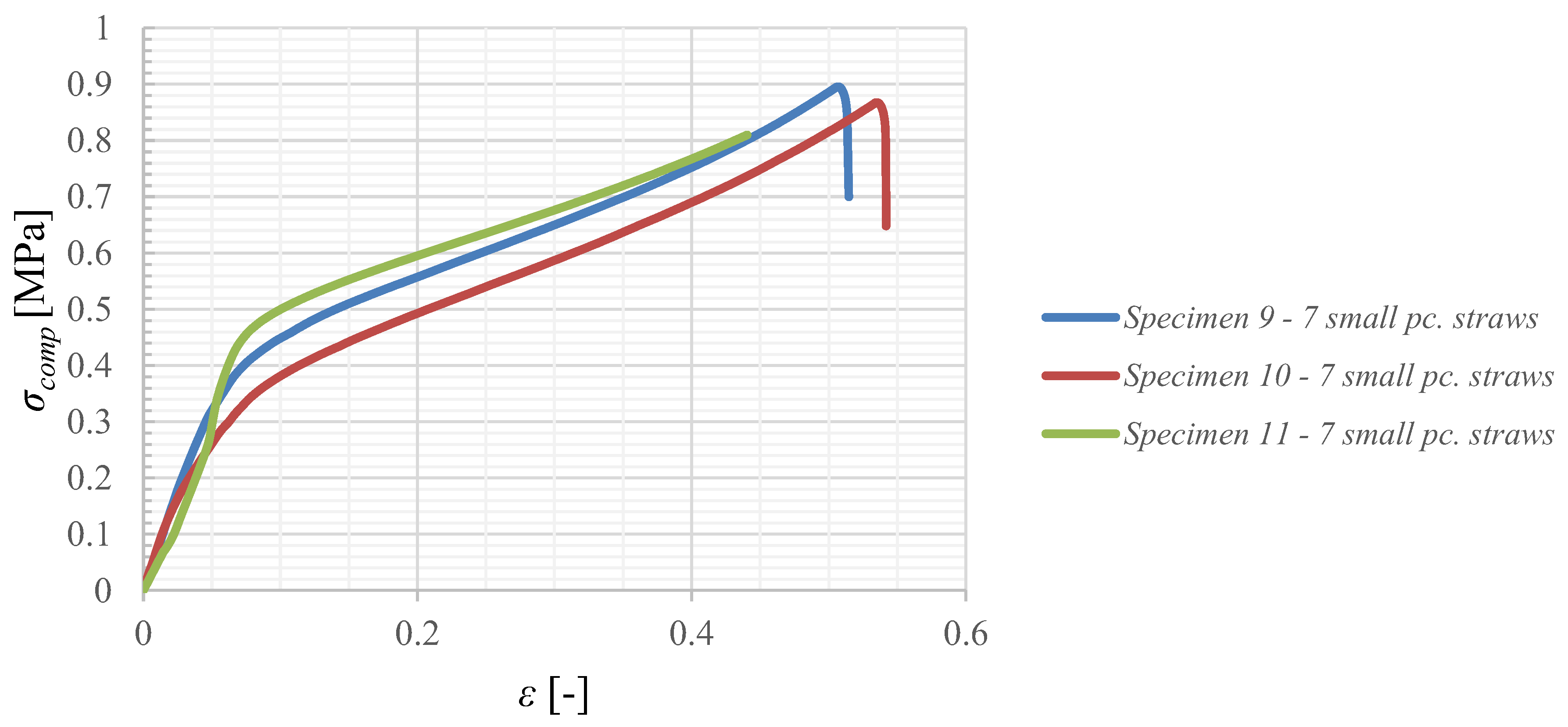
Figure 10 shows the strain-stress diagram of polystyrene specimens stiffened with small (5 mm) and large (11 mm) diameter plastic straws. This shows that we have achieved an improvement in terms of both strength characteristics and deformation characteristics.
Furthermore, tests were carried out with unstiffened specimens of higher density (Figure 11). In all cases, the sample with higher density had significantly better strength characteristics than the sample with lower density, but its mass was greater. Presumably, due to the smaller air volume, its thermal properties change in an unfavorable direction in terms of insulation.
4.3. FEM Analysis
In accordance with the mechanical tests, finite element simulations in the ANSYS environment were performed as well. The material database of the software includes polystyrene as a raw material, but mechanical properties are not assigned. Data on this can be found in the literature; however, these values depend to a large extent on the degree of expansion of the PS raw material, as well as on the production method. From our experimental tests, the value of the tension during the load was determined,
the value of deformation,
from which the value of the flexibility factor,
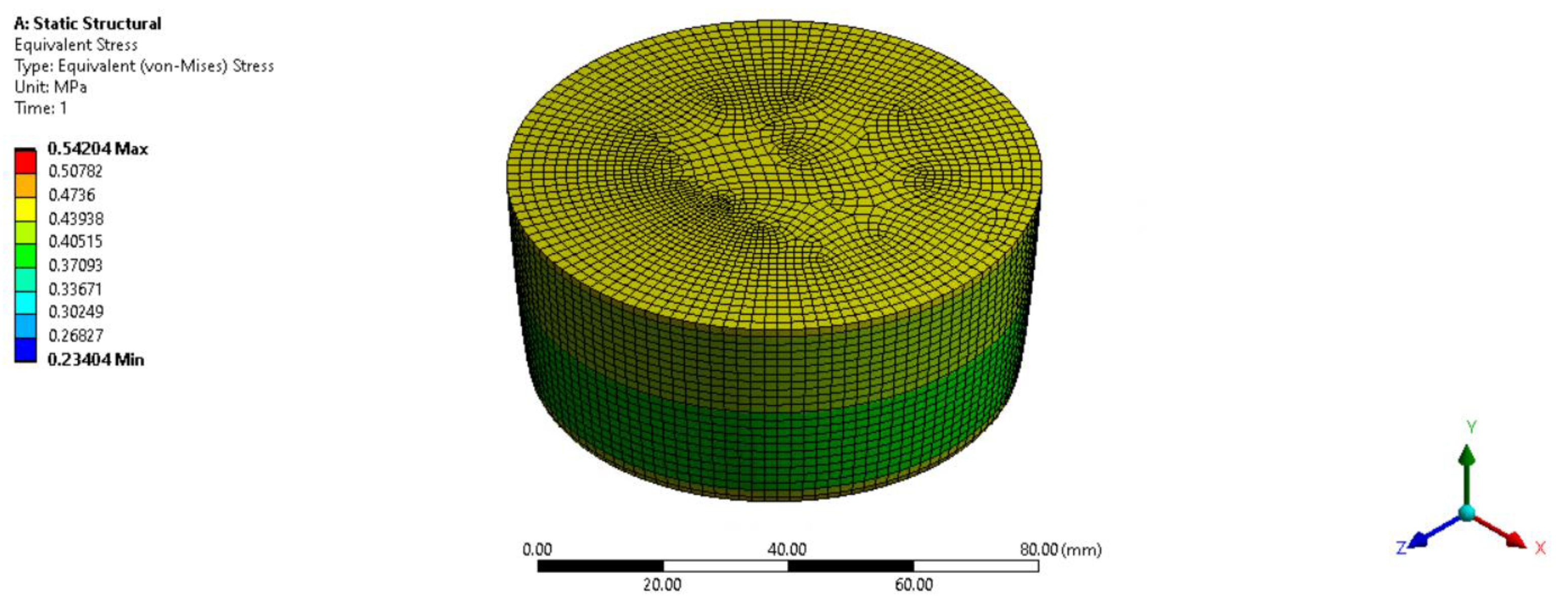
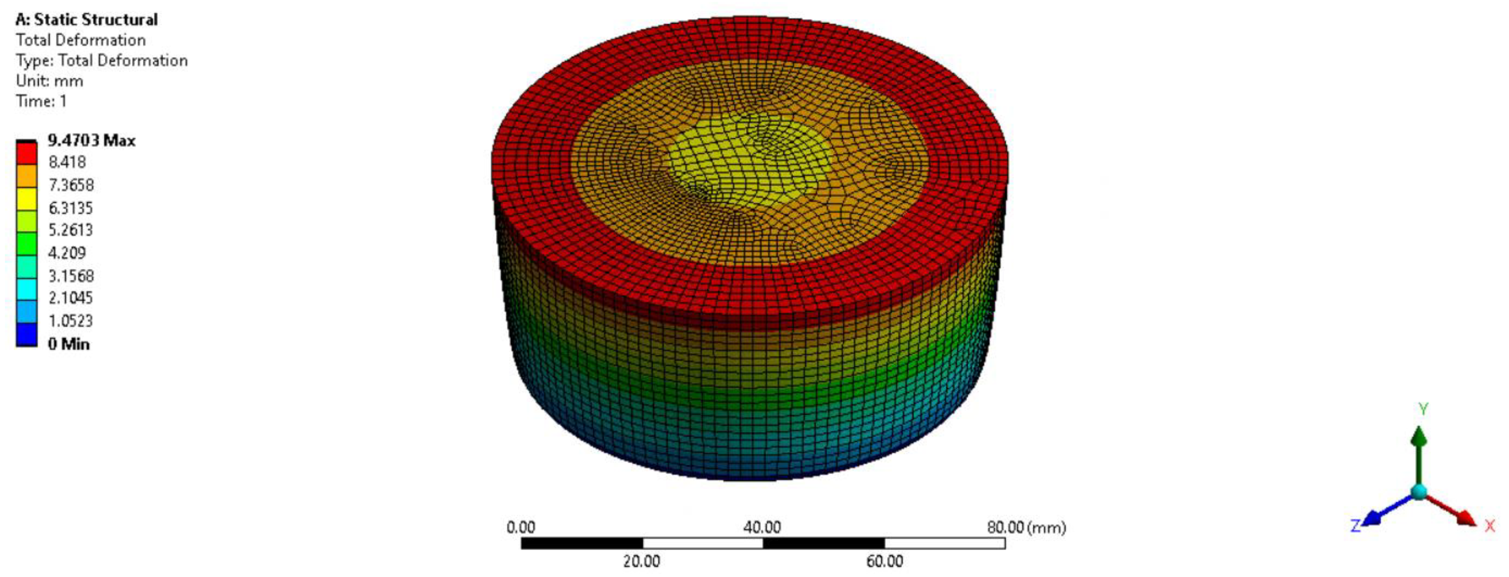
The finite element simulations were performed with these values, from which we obtained the following results shown in Figure 12 and Figure 13.
Owing to the modular structure of ANSYS, the thermal simulation can also be carried out, and since the geometric model was ready, only the boundary conditions had to be changed (grip plus load for the strength task, temperature or insulation of the surfaces for the heat conduction task). It is also possible to examine the thermal properties of the deformed test piece. The explanation for this is that less air space remains in the compressed material due to the load, therefore the polystyrene particles are in contact with each other to a much greater extent, which means that the thermal conductivity of the test piece will increase. This effect is not taken into account by the software therefore the change of the heat conductivity factor must be entered in the form of a function.
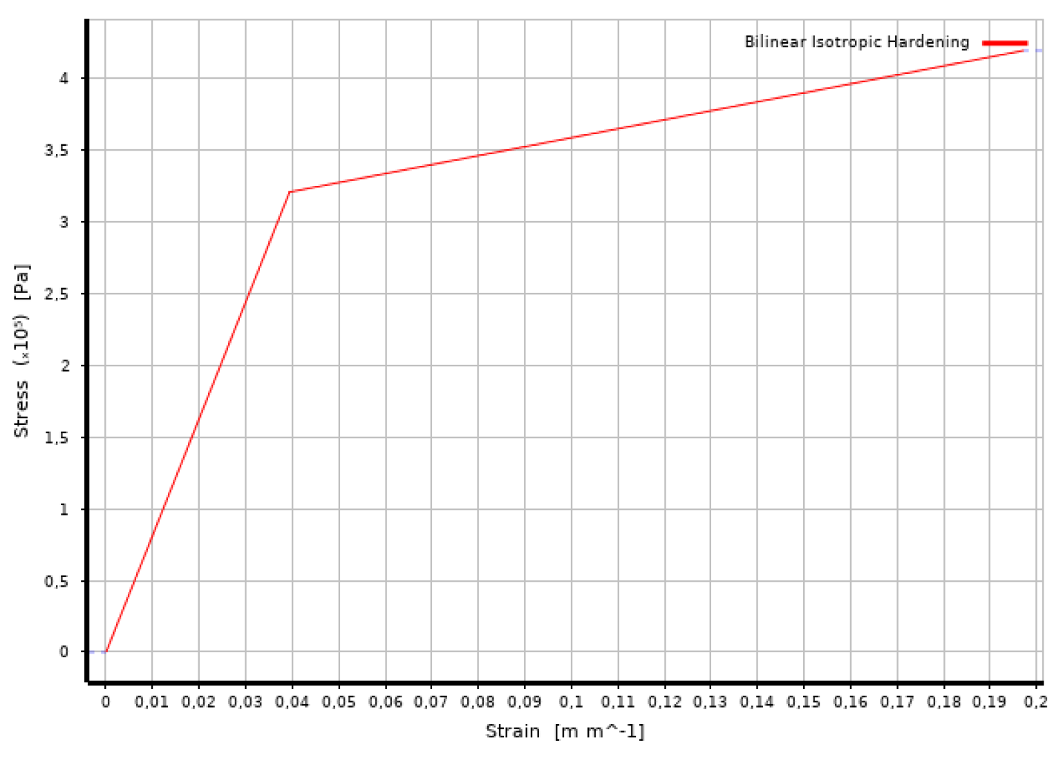
According to the measurements, the bilinear isotropic material model has been chosen for the numerical simulations. With this material model, the numerical results produced practically the same results as those obtained from the experiments. This bilinear isotropic hardening process was defined with three material properties, with the Young’s modulus, the yield strength and tangent modulus. The theoretical behavior of such a material is shown in Figure 14.
The two characteristic moduli are practically proportional to the slope of the lines drawn in the figure, and the yield strength is the point where the slopes are connected. The initial stage is the yield strength, and the second stage is the tangent modulus. The specimens prepared for the experiments have the following characteristics:
- the Young’s modulus is 8.1378 MPa,
- the yield strength is 0.321 MPa, and
- the tangent modulus is 0.6258 MPa.
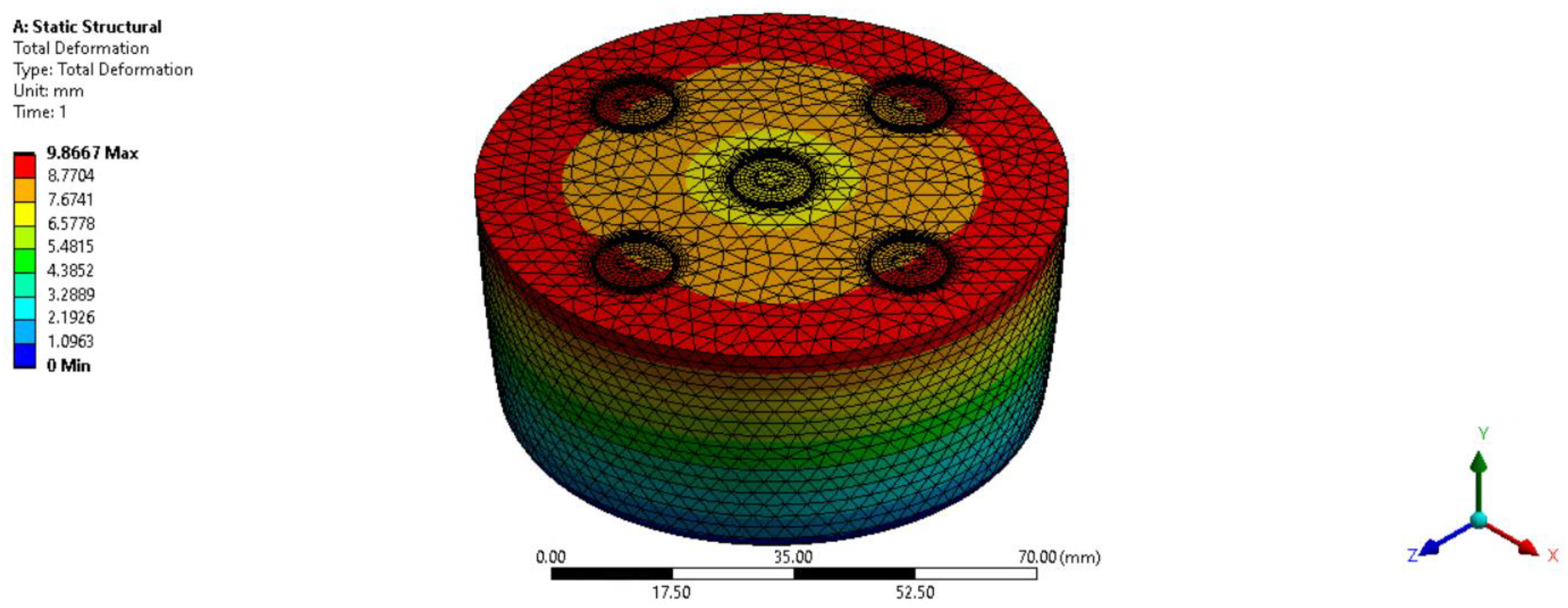
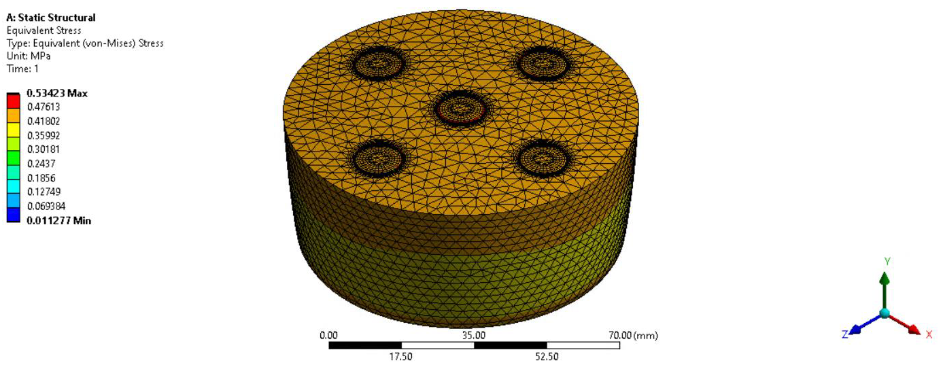
The finite element simulations of the reinforced test pieces with plastic waste are currently executed. During the simulation tests, the fact that the EPS material with a heterogeneous system contains a completely different material in terms of strength causes difficulties. During the simulation tests, it is necessary to solve a contact problem, which takes into account the tensions and possible displacements between the EPS and the plastic. According to our preliminary opinion, since the plastic, hollow bodies are also filled with PS material and they also expand, a hydrostatic load is practically created on the outer and inner surface of the plastic cylinder, which prevents the plastic elements from collapsing. Based on our experiments, this kind of load has a favorable effect on the strength properties of the product. The primary FEM tests have already been completed and the results are shown in Figure 15 and Figure 16. The mechanical models still need to be specified.
It can be seen from the Figure 12, Figure 13, Figure 15 and Figure 16 that the simulation results and the measurement results show a good approximation. The results are summarized in Table 4:
In the case of the material with a composite structure, it was necessary to generate the strain-stress diagram characteristic of the material from the measurement data, which was solved by function fitting.
4.4. CFD Analysis
In the course of our research, we also investigated reinforced and unreinforced PS test pieces using numerical flow methods.
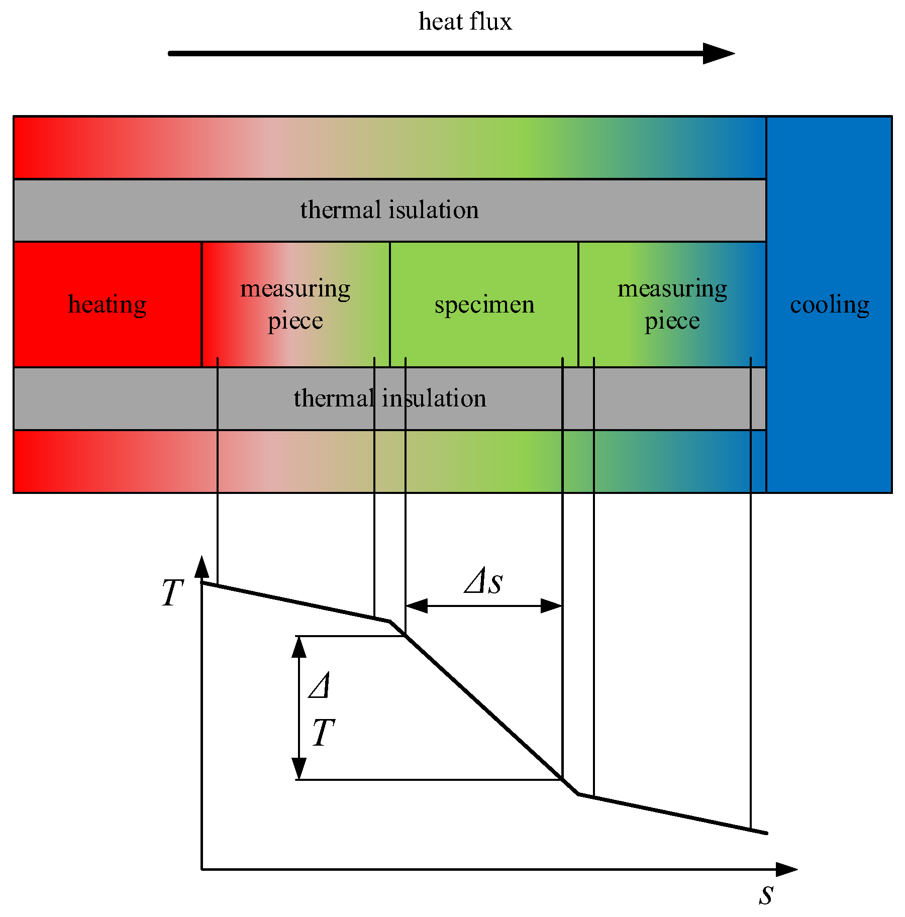
Figure 17 shows the principle diagram of the measurement of the thermal conductivity factor. Hot and cold surfaces with a constant temperature (these energies can come from some kind of high mass flow or a well-regulated source) were needed to be provided and two known materials (measuring pieces) with exact thermal conductivity factors were needed. In the arrangement shown in the figure, at least 6 temperature transmitters were needed and we needed to know the distances between them. Using the method described above, the thermal conductivity of the sample we developed can be determined. Figure 17 shows vertical lines between the schematic drawing and the temperature curve which symbolize the geometric position of the thermocouples.
The simulations were performed with SC/Tetra and ANSYS Workbench Steady State Thermal software.
In both cases, it was necessary to create a geometric model. When creating the model, a geometry was used according to the new, square-shaped forming chamber. During the tests, the whole volume temperature of 20 °C was assumed as initial condition and the boundary conditions were:
- initial temperature of upper surface: 100 °C,
- initial temperature of lower surface: 20 °C,
- thermal conductivity of PS: 0.038 W/mK,
- stiffening material (LDPE) thermal conductivity: 0.33 W/mK,
- side walls assumed as adiabatic walls.
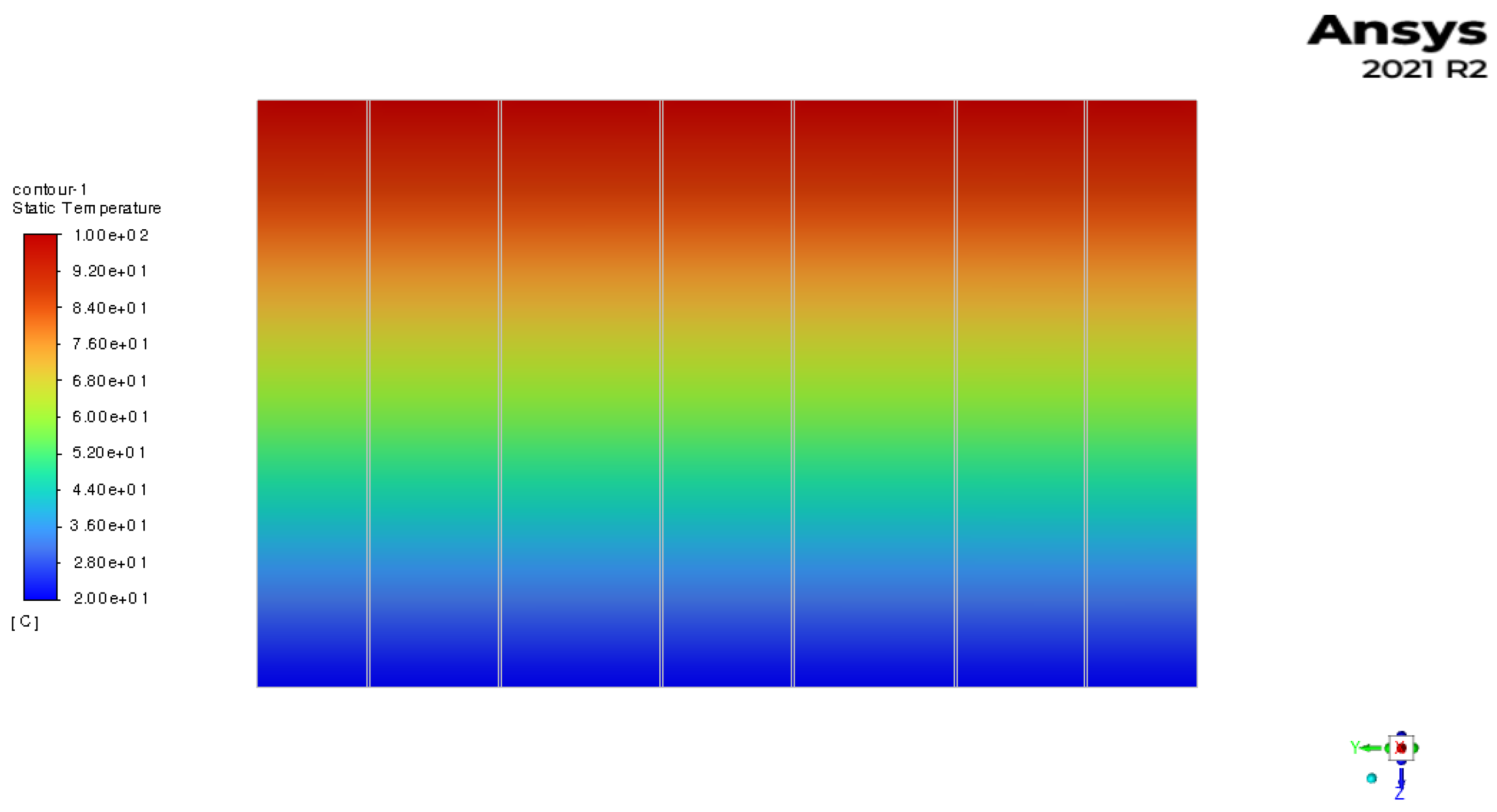
The result according to SC/Tetra is shown in Figure 18.
Table 5 shows the obtained specific heat fluxes in the different simulation cases.
Based on the SC/Tetra result, it can be established that the combined thermal conductivity of the reinforced polystyrene insulation material with a composite structure changed to 0.039 W/mK, which results in an increase of approximately 5%.
5. Summary
One of the most important keywords in our current economic life is the circular economy, which means extending the life of a given product as long as possible. The largest part of our society’s non-recycled waste is made up of plastics. The recycling of plastics is a high priority these days. The way of reusing plastic waste that we are researching is to reinforce PS foams with plastic-based straws. The EPS and XPS materials were presented in the article. We have described the production, structural constructions, mechanical properties and areas of use of these materials. The two materials are chemically the same, but their structure and mechanical properties are different due to their production using different processes.
The measurement and simulation studies used in the case of expanded polystyrene found in the literature were presented above, from which it can be concluded that the correct modeling of this material is a very complicated task, in which one of the main reasons is the material’s multi-stage stress-strain curve. During the simulations, the authors overwhelmingly used the LS-DYNA software because of the built-in favorable material models applicable to foams. In addition, in some cases, ABAQUS was also used, whose material model of the built-in crushable foam produced almost the same results as the measurements in the quasi-static case, but in the case of multiple loads, the model could not fully reproduce the real values, while with the LS—by correcting the parameters of the material model in the DYNA software, these types of loads could also be simulated.
In Section 4, we briefly presented the method of manufacturing the sample pieces and also described the measurements and simulation results. Based on the results, it can be stated that an improvement in strength can be achieved by placing plastic, cylindrical elements in the polystyrene filler. Additional tasks included eliminating the quality differences that arise during the production process, which is why we designed a new type of production chamber. It is necessary to carry out further pressure tests so that the results can be reliably used during the simulation. In the case of plastic elements, it is necessary to examine the optimal amount and distribution, which we want to verify basically with simulation tools.
The bilinear isotropic material model has been chosen for the numerical simulations. Based on that material model, the results of the numerical analysis showed the same results. This bilinear isotropic hardening process was defined with three material properties: the Young’s modulus, the yield strength and tangent modulus.
Author Contributions
Conceptualization, G.L.S. and Z.S.; software, B.S. and M.P.; investigation, G.L.S., M.P. and Z.S.; writing—original draft preparation, K.V. and Z.S.; writing—review and editing, B.S., G.L.S. and M.P.; visualization, M.P.; supervision G.L.S. and Z.S.; project administration, K.V. All authors have read and agreed to the published version of the manuscript.
Funding
This research received no external funding.
Institutional Review Board Statement
Not applicable.
Informed Consent Statement
Not applicable.
Data Availability Statement
Not applicable.
Conflicts of Interest
The authors declare no conflict of interest.
References
- Single-Use Plastics: New EU Rules to Reduce Marine Litter. Available online: https://ec.europa.eu/commission/presscorner/detail/en/IP_19_2631 (accessed on 29 September 2022).
- DIRECTIVE (EU) 2018/844 OF THE EUROPEAN PARLIAMENT AND OF THE COUNCIL of 30 May 2018 Amending Directive 2010/31/EU on the Energy Performance of Buildings and Directive 2012/27/EU on Energy Efficiency (Text with EEA Relevance). Available online: https://eur-lex.europa.eu/legal-content/HU/TXT/PDF/?uri=CELEX:32018L0844&from=ES (accessed on 29 September 2022).
- Directive 2010/31/EU of the European Parliament and of the Council of 19 May 2010 on the Energy Performance of Buildings. Available online: https://eur-lex.europa.eu/legal-content/EN/TXT/PDF/?uri=CELEX:32010L0031&from=HU (accessed on 29 September 2022).
- Almalkawi, A.T.; Soroushian, P.; Shrestha, S.S. Evaluation of the Energy-Efficiency of an Aerated Slurry-Infiltrated Mesh Building System with Biomass-Based Insulation. Renew. Energy 2019, 133, 797–806. [Google Scholar] [CrossRef]
- Rojas, C.; Cea, M.; Iriarte, A.; Valdés, G.; Navia, R.; Cárdenas-R, J.P. Thermal insulation materials based on agricultural residual wheat straw and corn husk biomass, for application in sustainable buildings. Sustain. Mater. Technol. 2019, 20, e00102. [Google Scholar] [CrossRef]
- Khalaj, O.; Siabil, S.M.A.G.; Tafreshi, S.N.M.; Kepka, M.; Kavalir, T.; Křížek, M.; Jeníček, Š. The experimental investigation of behaviour of expanded polystyrene (EPS). IOP Conf. Ser. Mater. Sci. Eng. 2020, 723, 012014. [Google Scholar] [CrossRef]
- Nikbin, I.M.; Golshekan, M. The effect of expanded polystyrene synthetic particles on the fracture parameters, brittleness and mechanical properties of concrete. Theor. Appl. Fract. Mech. 2018, 94, 160–172. [Google Scholar] [CrossRef]
- Miskinis, K.; Dikavicius, V.; Buska, A.; Banionis, K. Influence of EPS, mineral wool and plaster layers on sound and thermal insulation of a wall: A case study. Appl. Acoust. 2018, 137, 62–68. [Google Scholar] [CrossRef]
- Giuliani, F.; Autelitano, F.; Garilli, E.; Montepara, A. Expanded polystyrene (EPS) in road construction: Twenty years of Italian experiences. Transp. Res. Procedia 2020, 45, 410–417. [Google Scholar] [CrossRef]
- Lassen, C.; Warming, M.; Kjølholt, J.; Jakobsen, L.G.; Vrubliauskiene, N.; Novichkov, B. Survey of Polystyrene Foam (EPS and XPS) in the Baltic Sea: Final Report; Danish Fisheries Agency; Ministry of Environment and Food of Denmark: Copenhagen, Denmark, 2019.
- Woestman, J. Selecting Polystyrene Foam where Moisture Exposure Occurs. Available online: https://www.constructionspecifier.com/selecting-polystyrene-foam-where-moisture-exposure-occurs/ (accessed on 29 September 2022).
- Chen, W.; Hao, H.; Hughes, D.; Shi, Y.; Cui, J.; Li, Z.X. Static and dynamic mechanical properties of expanded polystyrene. Mater. Des. 2015, 69, 170–180. [Google Scholar] [CrossRef]
- Bertholf, D.; Karnes, C.H. Two-Dimensional Analysis of the Split Hopkinson Pressure Bar System? Pergamon Press: Oxford, UK, 1975. [Google Scholar]
- Shah, Q.H.; Topa, A. Modeling large deformation and failure of expanded polystyrene crushable foam using LS-DYNA. Model. Simul. Eng. 2014, 2014, 292647. [Google Scholar] [CrossRef] [Green Version]
- Krundaeva, A.; de Bruyne, G.; Gagliardi, F.; van Paepegem, W. Dynamic compressive strength and crushing properties of expanded polystyrene foam for different strain rates and different temperatures. Polym. Test. 2016, 55, 61–68. [Google Scholar] [CrossRef] [Green Version]
- Masso-Moreu, Y.; Mills, N.J. Impact compression of polystyrene foam pyramids. Int. J. Impact Eng. 2003, 28, 653–676. [Google Scholar] [CrossRef]
- Slik, G.; Vogel, G.; Chawda, V. Material Model Validation of a High Efficient Energy Absorbing Foam. In Proceedings of the 5th German LS-DYNA Forum ’06, Ulm, Germany, 12–13 October 2006. [Google Scholar]
- Ozturk, U.E.; Anlas, G. Finite element analysis of expanded polystyrene foam under multiple compressive loading and unloading. Mater. Des. 2011, 32, 773–780. [Google Scholar] [CrossRef]
- Coquard, R.; Baillis, D.; Quenard, D. Numerical and experimental study of the IR opacification of polystyrene foams for thermal insulation enhancement. Energy Build. 2019, 183, 54–63. [Google Scholar] [CrossRef]
- Sayadi, A.A.; Tapia, J.V.; Neitzert, T.R.; Clifton, G.C. Effects of expanded polystyrene (EPS) particles on fire resistance, thermal conductivity and compressive strength of foamed concrete. Constr. Build. Mater. 2016, 112, 716–724. [Google Scholar] [CrossRef]
- Cheng, J.; Pan, Y.; Yao, J.; Wang, X.; Pan, F.; Jiang, J. Mechanisms and kinetics studies on the thermal decomposition of micron Poly (methyl methacrylate) and polystyrene. J. Loss Prev. Process Ind. 2016, 40, 139–146. [Google Scholar] [CrossRef]
Figure 1.
Base wall with EPS plaster.

Figure 2.
EPS stress-strain diagram.

Figure 3.
Steam system used for EPS production. 1: Boiler, 2: Control valve, 3: Steam header, 4: Valve, 5: Throttle valve.
Figure 3.
Steam system used for EPS production. 1: Boiler, 2: Control valve, 3: Steam header, 4: Valve, 5: Throttle valve.

Figure 4.
Schematic drawing of molding chamber.

Figure 5.
Sample pieces (numbering from the upper left corner).

Figure 6.
Chamber of pre-foaming.

Figure 7.
Chamber of manufacturing the sample piece.

Figure 8.
Pressing test set up. 1—pressing machine, 2—force measuring cell, 3—clamping structure, 4—tested specimen, 5—displacement transmitter, 6—Quantum X A/D measurement data collector, 7—computer.
Figure 8.
Pressing test set up. 1—pressing machine, 2—force measuring cell, 3—clamping structure, 4—tested specimen, 5—displacement transmitter, 6—Quantum X A/D measurement data collector, 7—computer.

Figure 9.
Measured results of normal and straw reinforced polystyrene.

Figure 10.
Measured results for polystyrene reinforced with large straws.

Figure 11.
Measured results for polystyrene reinforced with small straws.

Figure 12.
Displacements of the tested specimen (deformed state).

Figure 13.
Reduced stresses of the tested specimen (deformed state).

Figure 14.
Theoretic diagram of a bilinear hardening model (from ANSYS).

Figure 15.
Deformation in the case of 5 large straws (to withstand a load of 2000 N).

Figure 16.
State of stress for 5 large straws (under a load of 2000 N).

Figure 17.
Schematic diagram of thermal conductivity measurement.

Figure 18.
ANSYS-Fluent simulation result.


Table 1.
EPS material properties.
| Properties | EPS70 | EPS100 | EPS150 | EPS200 |
|---|---|---|---|---|
| Density, kg/m3 | 13.5 | 18.0 | 23.0 | 28.0 |
| Initial elasticity modulus, MPa | 2.5 | 4.0 | 5.0 | 7.5 |
| Compressive strength at a 10% axial load, kPa | 70 | 110 | 135 | 200 |
| Thermal conductivity, W/mK | 0.039 | 0.037 | 0.035 | 0.033 |
Table 2.
Main physical properties of EPS and XPS.
| Physical Property | EPS70 | XPS |
|---|---|---|
| Density, kg/m3 | 13.5 | 50 |
| Thermal conductivity, W/mK | 0.039 | 0.03 |
| Moisture absorption capacity | 5 | 1 |
| R-value (appr. 24 °C, m2 K/W) | 4.1 | 5.0 |
| Pressure resistance, kPa | 70 | 100–690 |
Table 3.
Properties of the measured specimens.
| Specimen ID | Additive Material | Density (kg/m3) |
|---|---|---|
| Specimen 1 | none | 87.2 |
| Specimen 2 | 2 g natural wheat straw | 79.9 |
| Specimen 3 | none | 87.2 |
| Specimen 4 | 2 g natural wheat straw | 87.6 |
| Specimen 5 | 5 pieces Ø12 mm PE straw | 96.9 |
| Specimen 6 | 5 pieces Ø12 mm PE straw | 95.9 |
| Specimen 7 | 5 pieces Ø12 mm PE straw | 125.21 |
| Specimen 8 | 5 pieces Ø12 mm PE straw | 129.9 |
| Specimen 9 | 7 pieces Ø8 mm PE straw | 96.9 |
| Specimen 10 | 7 pieces Ø8 mm PE straw | 104.9 |
| Specimen 11 | 7 pieces Ø8 mm PE straw | 121.6 |
Table 4.
Comparison of the measured and simulated values.
| Measured Data | Simulation Value | |
|---|---|---|
| Compression of unbraced specimen | 8.42 mm | 8.3 mm |
| Compression of stiffened specimen | 9.53 mm | 9.8 mm |
Table 5.
Comparison of the measured and simulated values.
| SC/Tetra Reinforced | ANSYS Reinforced | Analytical Calc. Unreinforced Case | |
|---|---|---|---|
| Heat flow W/m2 | 44.8 | 44.9 | 43 |
Disclaimer/Publisher’s Note: The statements, opinions and data contained in all publications are solely those of the individual author(s) and contributor(s) and not of MDPI and/or the editor(s). MDPI and/or the editor(s) disclaim responsibility for any injury to people or property resulting from any ideas, methods, instructions or products referred to in the content. |
© 2022 by the authors. Licensee MDPI, Basel, Switzerland. This article is an open access article distributed under the terms and conditions of the Creative Commons Attribution (CC BY) license (https://creativecommons.org/licenses/by/4.0/).
Share and Cite
MDPI and ACS Style
Voith, K.; Spisák, B.; Petrik, M.; Szamosi, Z.; Szepesi, G.L. Non-Conventional Reinforced EPS and Its Numerical Examination. Processes 2023, 11, 12. https://0-doi-org.brum.beds.ac.uk/10.3390/pr11010012
AMA Style
Voith K, Spisák B, Petrik M, Szamosi Z, Szepesi GL. Non-Conventional Reinforced EPS and Its Numerical Examination. Processes. 2023; 11(1):12. https://0-doi-org.brum.beds.ac.uk/10.3390/pr11010012
Chicago/Turabian StyleVoith, Katalin, Bernadett Spisák, Máté Petrik, Zoltán Szamosi, and Gábor L. Szepesi. 2023. "Non-Conventional Reinforced EPS and Its Numerical Examination" Processes 11, no. 1: 12. https://0-doi-org.brum.beds.ac.uk/10.3390/pr11010012
Note that from the first issue of 2016, this journal uses article numbers instead of page numbers. See further details here.