
Utilization of Cold Energy from LNG Regasification Process: A Review of Current Trends
by
 ,
,
Muhammad Haziq Noor Akashah
1,
Nor Erniza Mohammad Rozali
1,2,*,
Shuhaimi Mahadzir
1,2 and
Peng Yen Liew
3 1
Department of Chemical Engineering, Universiti Teknologi PETRONAS, Seri Iskandar 32610, Malaysia
2
Centre for Systems Engineering (CSE), Institute of Autonomous Systems, Universiti Teknologi PETRONAS, Seri Iskandar 32610, Malaysia
3
Malaysia-Japan International Institute of Technology, Universiti Teknologi Malaysia, Jalan Sultan Yahya Petra, Kuala Lumpur 54100, Malaysia
*
Author to whom correspondence should be addressed.
Processes 2023, 11(2), 517; https://0-doi-org.brum.beds.ac.uk/10.3390/pr11020517
Submission received: 12 January 2023
/
Revised: 27 January 2023
/
Accepted: 31 January 2023
/
Published: 8 February 2023
(This article belongs to the Special Issue Chemical Engineering and Technology)
Abstract
:Liquified natural gas (LNG) is a clean primary energy source that is growing in popularity due to the distance between natural gas (NG)-producing countries and importing countries. The large amount of cold energy stored in LNG presents an opportunity for sustainable technologies to recover and utilize this energy. This can enhance the energy efficiency of LNG regasification terminals and the economic viability of the LNG supply chain. The energy stored in LNG in the form of low temperatures is referred to as cold energy. When LNG is regasified, or converted back into its gaseous form, this cold energy is released. This process involves heating the LNG, which causes it to vaporize and release its stored energy. The current state-of-the-art techniques for LNG cold energy utilization, including power generation, air separation, traditional desalination, and cryogenics carbon dioxide (CO2) capture are discussed in this review. While most of the current LNG cold energy utilization systems are presented, potential future applications are also discussed. The commercialization of sustainable technologies, such as improvement strategies for LNG cold energy utilization, is becoming increasingly important in the energy industry.
1. Introduction
The increasing demand for energy in recent years has been driven by factors such as increasing population and economic growth. As the world population is expected to increase by 22% in 2040 and the gross domestic product (GDP) is predicted to increase by 75% over the next 30 years, it is likely that global energy consumption will continue to rise [1]. While it is forecasted that energy consumption will increase by 0.6–1.5% per year between 2015 and 2040, this growth rate will be slower than what was seen between 2000 and 2013 [2]. It is important to consider the impact of greenhouse gas emissions [3], which contribute to global warming [4] and climate change, in relation to energy demand. The burning of fossil fuels, the main source of energy globally, leads to the release of greenhouse gases such as carbon dioxide (CO2), carbon monoxide, nitrogen oxide, and sulfur dioxide. In the past two decades, emissions have grown at a rate of 1.2% per year, with CO2 emissions increasing by over 50% worldwide in the past 25 years, with the power generation sector being the main contributor [5].
As the demand for energy continues to rise, it is important to consider the environmental impact of different energy sources. While fossil fuels, such as coal and oil, have traditionally been the primary sources of energy, natural gas (NG) is becoming increasingly popular [6] due to its cleaner burning properties [7]. NG emits lower levels of harmful greenhouse gases [8], such as CO2 [9] and sulfur dioxide, compared to other fossil fuels, making it a more environmentally friendly option [10]. NG is a convenient energy source that is easy to transport due to its specific density. It is also a high-energy source, making it an efficient choice for many uses. NG is often considered a clean and efficient energy source due to its low carbon emissions when compared to other fossil fuels. According to data from major gas companies, NG is expected to continue growing in popularity, with a projected increase of 1.7–2.2% per year [11]. It is projected that by 2030, it will become the second primary energy resource [12].
The transportation of NG is a critical aspect of the supply chain, and two main methods are currently used: pipelines and liquified natural gas (LNG). Pipelines are the traditional option and are most effective for shorter distances, usually less than 1000 km. LNG is better suited for longer distances, typically more than 3500 km [13]. In addition to traditional methods of natural gas transportation, there are new methods, such as Gas to Liquid (GTL), Gas to Wire (GTW) [14], Gas to Tank (GTT or CNG), and Gas to Solid (GTS), being developed, but they are not yet practical due to the need for further research and technological advancements.
LNG is produced by cooling NG to cryogenic temperatures, resulting in a liquid form that is easier to transport and store than NG in its gaseous form. LNG is primarily composed of methane, with a heating value of around 21–24 MJ/L [15]. Its density ranges between 400 and 500 kg/m3 [16], resulting in a lower density than water, and its volume is significantly reduced when compared to NG in its gaseous form. The LNG supply process involves the extraction, liquefaction, transportation, and regasification of NG [17], with the traditional method involving pipelines and LNG carriers. More recently, the use of floating liquefied natural gas (FLNG) has emerged as a way to extract, transport, and import LNG from offshore reserves, offering convenience and efficiency compared to traditional methods [18]. The safety of LNG has also been extensively researched [19], with no recorded incidents of accidents or spills in the transportation of LNG. Overall, LNG has the potential to play a significant role in meeting the increasing global energy demand while mitigating greenhouse gas emissions.
In order to deliver LNG to consumers, it is first shipped from the production location to a receiving terminal, where it is unloaded from carriers and transferred to storage tanks. Figure 1 illustrates the essential process of an LNG receiving terminal. From the terminal, LNG is pumped through a pipeline to vaporizers, where it is heated and returned to a gaseous state. This process, known as regasification, is important for ensuring the safe and efficient delivery of LNG to consumers. The regasification process is used to convert LNG back into its gaseous state so it can be transported through pipelines and used as a source of energy. The process involves heating the LNG to a temperature above its boiling point, typically around −162 °C, using a variety of methods, such as ambient air, seawater, or waste heat. The heat is transferred to the LNG, causing it to vaporize and release its stored cold energy. It is carried out in specialized facilities known as LNG receiving terminals, which are equipped with specialized equipment such as LNG arms [13] and vaporizers [20]. The regasification process is also carefully monitored to ensure safety, with measures in place to handle any excess gas that may be produced during the process.
While LNG is a clean and efficient energy source, the cold energy produced during the regasification process is often released into the environment through vaporizers and warmed by external substances. Furthermore, releasing cold energy into the surrounding environment can be problematic because it may harm aquatic life and the wasted energy could have been used to power other systems or processes instead [21]. This wasted energy can contribute to inefficiencies [22] in the overall energy system and increase the environmental impact of the LNG supply chain. By capturing and making use of the cold energy, it is possible to enhance the energy efficiency of LNG regasification terminals and the economic viability of the LNG supply chain. Additionally, utilizing cold energy can help to reduce greenhouse gas emissions [23] and contribute to a more sustainable energy system [24]. There have been many studies that reported applying this cold energy from the LNG regasification process [21]. Based on the last review article on the application of cold energy from the LNG regasification process published in 2019 [21], it has been identified that there has been recent advancement in terms of utilizing cold energy. Recent research has focused on the cost and power generated for power generation (combining cycle), as well as the efficiency of air separation units, the feasibility of CO2 capture, and the advancements in desalination process technology. Recent work on adapting LNG cold energy on data cooling centers and the efficiency of cold energy storage were also reviewed. Therefore, the purpose of this review is to fill these knowledge gaps by providing a comprehensive analysis of recent developments in these areas. Hence, this paper reviews the potential of utilizing the cold energy released during the regasification process of LNG based on recent developments and advancement in the past 5 years in utilizing LNG’s cold energy, especially in industrial sectors [25].
2. Trends of Current LNG Cold Energy Utilization
The cold energy in LNG holds unique properties that make it useful in various applications, especially in the oil and gas industry [26]. Cold energy is a valuable resource that is produced during the regasification of LNG. The process of vaporizing LNG in vaporizers generates a large amount of cold energy, which can be used in a variety of applications, such as power generation, air separation, desalination, CO2 capture, data center cooling, and cold storage [21]. However, it is important to consider the distribution pressure of natural gas when utilizing LNG cold energy, as the required pressure values can vary depending on the intended use of the gas. Additionally, while the amount of LNG cold energy produced is generally higher in larger systems, it is more beneficial to consider LNG cold exergy when designing cold utilization systems due to the inclusion of destruction and loss terms in the exergy concept [27].
2.1. Power Generation
The trade of LNG has seen a rapid growth in the past two decades [28]; however, with global warming on the rise, there is an increased need for sustainable solutions. Environmental policies are also becoming stricter, making it imperative to find ways to reduce greenhouse gas emissions. LNG cryogenic technology presents a solution to this problem, as it allows for the capture and utilization of the cold energy stored in LNG. This can be achieved by using cold energy to vaporize a working fluid, such as R-141b, which then expands through a turbine to generate electricity. This process can significantly increase the efficiency of the power generation process and reduce the overall costs, making it a promising opportunity for sustainable and cost-effective power generation. This not only increases the energy efficiency of LNG regasification terminals but also the economic benefit of the LNG supply chain. It can also be used for power generation [29], further reducing the dependence on fossil fuels and contributing to the reduction in greenhouse gas emissions.
2.1.1. Rankine Cycle
The Rankine cycle is a thermodynamic cycle that converts heat into work and is commonly used in power generation systems [30]. In the Rankine cycle, water is used as the working fluid and is heated to produce steam, which is then expanded through a turbine to generate power. The steam is then cooled, usually using cooled water or an air source, and condensed back into liquid form. The liquid that has undergone condensation is then pumped back into the heater to complete the cycle. On the other hand, the organic Rankine cycle (ORC) is a variant of the Rankine cycle that replaces water with an organic working fluid [31]. A study by Hung et al. [32] showed that the ORC is preferred over the Rankine cycle for the recovery of low-temperature waste heat due to the benefits it offers, such as increased efficiency and better performance, among others. ORCs can use a wider range of working fluids [33], allowing for a higher degree of flexibility in terms of operating conditions and waste heat source characteristics. In addition, ORCs can operate at lower temperatures [34] and pressures, making them more suitable for use with low-grade waste heat sources. ORCs also have higher exergetic efficiencies [35] compared to Rankine cycles, which means that more of the available thermal energy can be converted into useful work. ORCs typically have smaller and simpler components [36] compared to Rankine cycles, making them more compact and easier to maintain. Overall, ORCs are considered to be a favorable option in comparison to Rankine Cycles for recovering low-temperature waste heat. This is due to their ability to use a broader range of working fluids, operate at lower temperatures and pressures, and also exhibit higher exergetic efficiencies. Additionally, ORCs are relatively simple in terms of componentry.
As seen in Figure 2, the working fluid in an ORC undergoes compression, evaporation, expansion, and condensation to generate power. The condensation process uses LNG as a heat sink. The earliest ORC implementation in a practical engineering project that used LNG cold energy was in Japan in 1979. The ORC employing propane as the working fluid was claimed to have a power output of 1450 kW in the LNG terminal owned by the Osaka Gas business [37]. The investigations on using LNG cold energy in an ORC were primarily concerned with the choice of working fluid and cycle configuration in order to maximize the cold energy utilization [38]. The recent trends of utilizing cold energy from LNG in ORC are reviewed and summarized in this section.
The utilization of cold energy from the LNG regasification process to generate electricity through the use of cryogenic ORC and trilateral flash cycle (TFC) systems can be observed in a study by Daniarta et al. [40] in 2020. The authors examined the potential of utilizing cold energy from LNG regasification to generate electricity through the use of a cryogenic ORC and trilateral flash cycle (TFC)[40]. The performance of the systems was evaluated considering thermodynamic efficiency, environmental impact, and safety concerns. The results show that propane is the optimal working fluid for a single-stage cryogenic ORC system. It was found that single cryogenic ORC systems perform better in terms of net output power and efficiency compared to single cryogenic TFC systems. The study estimated that a net power output of around 320 MW could be recovered from cold energy by installing single-step cryogenic ORC units using propane as the working fluid in 26 novel LNG terminals.
Liu et al. [41] presented a method for utilizing the cold energy present in LNG during the regasification process at receiving terminals. The researchers found that an ORC system, which converts low-temperature heat into electricity, is the most promising technique for recovering cold energy compared to other different kinds of power generation technologies. However, the significant temperature difference between the low-temperature waste heat source and LNG caused a one-stage ORC system to struggle in effectively utilizing the available waste heat and cold energy from LNG. The researchers suggested an ORC system that utilizes a cascaded design as a solution. This system was improved through the use of a simulation-based optimization approach and a particle swarm optimization method. The highest net power output per unit of the integrated system was found to be 0.096 kWh per kilogram of LNG. This study highlights the potential for utilizing the cold energy present in LNG to generate electricity in a more energy-efficient and environmentally friendly way.
The study by Choi et al. [42] presented an optimization approach to investigate the potential of using an ORC in combination with a regasification plant of LNG to recover the cold energy. The focus of the optimization was on finding the optimal distribution of resources, such as thermal energy and equipment size, when there were limitations in both LNG cryogenic energy and the total heat transfer capacity of heat exchangers. In this study, it was established that as the overall thermal conductivity for the system design was increased, the ORC would need to handle a greater heat load and the total thermal conductivity would need to be focused on the evaporator. Additionally, when there is enough thermal conductivity for the system design, the priority order of heat exchanger sizes should be the evaporator, condenser, and trim heater. This research emphasized the significance of utilizing resources effectively in order to optimize the ORC systems in LNG regasification facilities.
Joy et al. [43] aimed to determine the potential of a cascaded three-stage ORC system in utilizing the cold energy from LNG to generate power. The research found that while a three-stage system had the highest potential for power generation, a dual-stage system that only utilized the first stage resulted in a lower power generation of 8.6% compared to the three-stage system. However, it had the advantage of being simpler in design and operation, as well as reducing the heat exchanger surface area by 20%. The study used sea water as the heat source and the working fluids evaluated were ethene, ethane, and propane. The research found that the optimal distribution of surface area and heat transfer resulted in uneven temperature differences in the heat exchangers, which led to increased power output.
A recent study by Tian and coworkers [44] proposed the use of an ORC for power generation through the recovery of waste heat from natural gas combined cycles. The energy effectiveness of the power generation cycle that used R-141b as the working fluid was 12.49%. The study found that directing more of the heat source to the ORC cycle led to an increase in the total exergy efficiency of the system. The simulation results show that the proposed system can produce 892.4 MWh of electricity annually. Additionally, the study also evaluated the economic aspect and found that the proposed scheme has a total annualized cost of USD 1,559,491.11 and a return on investment of USD 598,833.11 per year. Besides the above-cited recent studies that used cold energy from LNG regasification for power generation based on ORCs, other newly published studies are summarized and tabulated in Table 1 based on their power output and working fluid.
2.1.2. Brayton Cycle
The Brayton cycle is a thermodynamic cycle used in gas turbine engines to convert thermal energy into mechanical work [51]. It involves a continuous process of compressing a working fluid, heating the compressed fluid, expanding the heated fluid through a turbine, and finally releasing the waste heat to the environment. One potential application of the Brayton cycle is the utilization of cold energy from LNG regasification to generate power [27]. As LNG is vaporized during the regasification process, the cold energy contained within the LNG can be harnessed to drive the Brayton cycle and generate electricity. By using LNG as a heat sink, the Brayton cycle can efficiently recover this cold energy and contribute to the overall efficiency of the LNG regasification process. There have been several studies investigating the potential of utilizing cold energy from LNG regasification in a Brayton cycle, with the aim of maximizing power generation and system efficiency while minimizing complexity and cost. However, most of the studies were found to combine Brayton cycle with other cycle types.
A study from Khadse et al. [52] in 2018 focuses on the use of supercritical CO2 (S-CO2) Brayton cycles for waste heat recovery (WHR) from a gas turbine. The researchers used a genetic algorithm (GA) to optimize the performance of recuperated (RC) and recuperated recompression (RRC) configurations of the S-CO2 Brayton cycle. The optimization aimed to maximize power output from the exhaust stream. The results show that the RRC configuration had a higher power output than the RC configuration for the chosen exhaust gas mass flow rate. The economic analysis also showed that the optimized RRC cycle had a lower cost compared to a steam Rankine bottoming cycle. Figure 3 shows the S-CO2 recompression Brayton cycle proposed in the study [52]. Overall, the study suggests that the choice of the best cycle for WHR depends on the mass flow rate of the exhaust gas, and that S-CO2 Brayton cycles may be a promising option for WHR due to their compactness, low capital cost, and ability to work with a wide range of heat source temperatures. Siddiqui et al. [53] reported on the use of S-CO2 Brayton cycles in a cascaded arrangement with a secondary cycle to recover heat from a variety of sources. The performance of different working fluids in the secondary cycle and the effect of pressure drop on the overall performance of the combined system were assessed. The results of the energy and exergy analysis were discussed in relation to the existing literature and simulation results for standalone S-CO2 Brayton cycles. The study concludes that the use of S-CO2 Brayton cycles in a cascaded arrangement with a secondary cycle can be an effective method for recovering heat from various sources and improving the efficiency of power generation.
Cha et al. examined the use of the CO2 cycle in power generation, specifically in relation to LNG cold energy recovery [54]. The study presented a new configuration, a gas turbine–CO2 combined cycle power plant (GT-CO2 CCPP) with a gas turbine inlet air cooling (TIAC) and heat recovery (HR) system when using LNG cold energy. The TIAC and HR system cools the gas turbine inlet air using condensate CO2 in order to improve power output and efficiency. The study performed a simulation of a 62 MW medium-size gas turbine, which is commonly used in LNG terminals. The results of the simulation were compared to a conventional GT-steam CCPP and a GT-CO2 CCPP without the TIAC and HR system. It was found that the proposed configuration increased power output by 14.9% and efficiency by 2.1% compared to the GT-CO2 CCPP without it. Additionally, it was found that it increased the power output and efficiency by 25.4% and 11.5%, respectively, in comparison to the conventional GT-steam CCPP. This effect was reported to increase with ambient temperature.
Taheri et al. proposed a new system for solar power generation that utilizes a solar power tower that works in conjunction with a molten salt cycle [55]. The system aims to increase energy efficiency by incorporating a closed S-CO2 Brayton cycle and an open-cycle LNG as a heat sink and uses a cascade organic Rankine cycle that can function at low temperatures. The LNG is then utilized as an input for a solid oxide fuel cell after cooling down the power generation systems and for power generation. The study also examines the economic and thermodynamic performance of the system, analyzes the destruction of exergy, and carries out parametric studies to determine how different factors influence the performance of the system. To optimize the system, a genetic algorithm is used, and two objectives are considered: total cost rate and exergy efficiency. The results of multi-objective optimization indicate that the optimized system has a total product cost rate of 115.3 USD/h and an exergy efficiency of 71%. Additionally, the study notes that the exergy analysis highlights that the molten salt heat exchangers and the LNG heat exchangers have the highest rates of irreversibility and must be given priority when it comes to optimization. The study by Chen et al. [56] proposed a novel method for utilizing LNG as a clean fuel source by using CO2 and N2 as working fluids in a parallel power generation system. To boost its efficiency, the system includes a solar heating component. Furthermore, it addresses the issue of the solar system’s discontinuous operation by incorporating two serial turbines with different inlet parameters. The results of the thermodynamic analysis and multi-objective optimization show that the proposed system is more efficient and has less exergy loss compared to other systems, such as the hybrid N2 and LNG system that can include or exclude a heat recovery component, the integrated CO2 and LNG system, and LNG direct expansion configuration. Additionally, it was found that the system is more effective than most ORC systems and has lower complexity. The best net power output generated by the system was 12.4816 MW, with an energy efficiency of 17.25% and exergy efficiency of 29.90%.
The study by Sun et al. in 2022 examined a system that combines cooling, heating, and power generation utilizing the cold energy from LNG and high-temperature flue gas waste heat [57]. The system was composed of a three-stage parallel Rankine cycle combined with a single-stage Rankine cycle and an S-CO2 Brayton cycle. The performance of the system was evaluated using a variety of methods, including the first and second laws of thermodynamics, a specific energy costing method, and an exergoenvironmental analysis method. The system was optimized using the nondominated sorting whale optimization algorithm and the technique for order preference by similarity to the ideal situation. The study’s findings reveal that, under initial conditions, the system’s thermal efficiency was 41.68%, its exergy efficiency was 48.50%, its total product unit cost was 112.293 USD/GJ, and its sustainability index was 1.75. Following optimization, the exergy efficiency rose by 2.4%, and the exergoeconomy dropped by 8.277 USD/GJ. Other similar works on using cold energy from LNG via integration with other systems with the Brayton cycle are as tabulated in Table 2.
The Brayton cycle is considered to be safer to operate and easier to configure compared to the ORC system. The higher power consumption of the compressor, however, results in a lower net power production from the Brayton cycle compared to the ORC. One way to improve the Brayton cycle’s thermal efficiency and lower energy loss during the heat transfer process using LNG is to use mixed gas as the working fluid [61].
2.1.3. Kalina Cycle
The Kalina cycle, which was first introduced in 1984 [62], is an alternative to the Rankine cycle for combined power generation using a multi-component working fluid. It is similar in structure to the Rankine cycle but features a two-phase heat addition process [63]. Using an ammonia–water solution as the working fluid, the Kalina cycle can effectively extract cold energy from LNG. Its higher exergetic efficiency compared to the Rankine cycle is attributed to its ability to vary the temperature of the working fluid during evaporation, which reduces irreversibility and improves overall efficiency.
A study in 2018, carried out by Ghaebi et. al, detailed the use of LNG cold energy in the Kalina cycle [64]. A cascade Kalina cycle (CKC) power plant was proposed as a promising methodology for recovering waste heat in power plants using geothermal energy as the heat source and LNG as the thermal heat sink. The proposed system consists of a high-pressure Kalina cycle (HPKC) as the topping cycle and a low-pressure Kalina cycle (LPKC) as the bottoming cycle. The proposed system was optimized using a genetic algorithm (GA) approach to maximize net power, thermal efficiency, exergy efficiency, and the total sum unit cost of the product in both single- and multi-objective optimizations. The results show that the optimal values for these performance measures are 9044 kW, 29.87%, 43.19%, and 127.8 USD/GJ, respectively. A parametric study was also conducted to explore the factors that influence the thermal and exergy efficiencies of the system. It was found that increasing the geothermal inlet temperature, ammonia concentrations, and expansion ratios of the turbines and decreasing the second heat exchanger temperature and vapor generator pinch point temperature difference can increase the thermal efficiency. On the other hand, increasing the geothermal inlet temperature, expansion ratios of the first and second turbines, ammonia concentrations of the HPKC, decreasing the temperature of the second heat exchanger, the expansion ratio of the third turbine, and vapor generator pinch point temperature difference can increase the exergy efficiency. The total sum unit cost of product can be reduced by implementing a combination of strategies, such as increasing the geothermal inlet temperature, second heat exchanger temperature, and ammonia concentrations of the HPKC and LPKC while simultaneously decreasing the vapor generator pinch point temperature difference and expansion ratios of the turbines.
Zhang et al. [65] proposed a new energy system that combines liquid air energy storage (LAES) with the Kalina cycle (KC) called the KC-LAES. The system utilizes surplus compression heat from the LAES process to drive a KC system, which generates additional electricity. The performance of the KC subsystem was evaluated, and it was found that the optimal working fluid concentration and operating pressure for the KC-LAES system are 85% and 12 MPa, respectively. The results also show that the introduction of the KC significantly improves the compression heat utilization ratio of the LAES, leading to an increase in the round-trip efficiency (RTE) of the KC-LAES system. With a liquefaction pressure value of 8 MPa and an expansion pressure value of 4 MPa, the RTE of the KC-LAES system is 57.18%, while that of the baseline LAES (B-LAES) system is 52.16%. Overall, this study shows that the KC-LAES system is a promising solution for power generation using surplus compression heat.
In 2020, a new concept for integrating municipal air conditioning, electricity, and gas supplies was proposed and analyzed by Eveloy et al. [66] for reducing the carbon intensity of these supplies. The proposed system makes use of low-grade renewable or surplus heat and waste exergy as its energy source from the vaporization of LNG for refrigeration and power generation in a Kalina cycle. The analysis revealed that the system was able to generate significant amounts of refrigeration and useful power, with an efficiency of 33% based on the first law of thermodynamics and 35% based on exergetic efficiency. The use of a cryogenic heat sink in the Kalina subsystem’s condenser was found to significantly increase the system’s useful electrical output. The implementation of the system could lead to significant yearly net power savings, NG savings, and CO2 emission reductions, with corresponding monetary savings and short payback periods. Fang et al. [67] then reported a combined cooling, heating, and power system that utilizes LNG cold energy and exhaust gas waste heat for energy recovery and utilization. The system consists of a three-stage ORC, a Kalina cycle, and LNG direct expansion. Through thermodynamic analysis, it was found that the system had a net output power of 1257.708 kW, a thermal efficiency of 43.43%, and an exergy efficiency of 70.4%. The effects of various parameters on the system performance were analyzed, and exergoeconomic analysis was used to calculate the total product unit cost of the system, which was found to be 51.1 USD/GJ. Single- and multi-objective optimizations of the system were also conducted, with the optimization results showing that the system had a maximum exergy efficiency of 80.49% and a minimum total product unit cost of 48.04 USD/GJ.
Ghorbani et al. [68] developed a two-stage ejector cooling system to produce continuous refrigeration at a temperature of 171 K. The system utilized propane and ethylene as working fluids in two separate ejector cycles, with the second cycle utilizing the refrigeration provided by the first cycle as a heat source. The Kalina power cycle was also utilized in the system to reduce the power consumption and increase the coefficient of performance of the refrigeration cycle. The system was powered by a simulated 48 MW grid-connected photovoltaic unit located in Chabahar, Iran, which had an annual performance ratio of 79.3% and produced an average of 80,224 MWh per year. Phase change material was also used to provide continuous cold duty to the end user. The exergetic evaluation of the system showed that the majority of exergy destruction occurred in the photovoltaic panels, followed by compressors, heat exchangers, and ejectors. The exergy efficiency of the total system was 28.97%. Sensitivity analysis revealed that increasing the operating pressure of the Kalina cycle to 1500 kPa resulted in a decrease in the power consumption of the system and an increase in the coefficient of performance of the refrigeration cycle.
Nabat et al. [69] recently presented a novel energy storage system that combines LAES with the Kalina cycle and a thermoelectric generator. This hybrid system aims to address the low efficiency of LAES and enhance the stability of renewable energy sources through peak shaving and peak shifting. It was found that the system had a round trip efficiency of 61.6% and a total storage energy density of 109.4 MJ/m3. Based on an economic study of the system in California, it was demonstrated that it would take 3.5 years for the system to pay for itself, with projected profits exceeding USD 26 million during its economic book life.
In conclusion, all three cycles—the ORC, the Brayton cycle, and the Kalina cycle—have the potential to effectively utilize cold energy for power generation. The ORC has the ability to recover low-grade waste heat and convert it into electrical power, with efficiencies ranging from 8 to 13%. The Brayton cycle, which is also known as the gas turbine cycle, is a widely used power generation technology that can utilize high-temperature heat sources such as fossil fuels or nuclear reactions. The Kalina cycle, which is a variant of the Brayton cycle, can utilize low-grade heat sources such as waste heat or solar energy, and has demonstrated efficiencies of 25–40% in waste heat recovery applications. All three cycles have their own advantages and limitations, and the most suitable cycle for a particular application will depend on the specific heat source and the desired level of efficiency.
2.2. Air Separation
A distillation column is used in the cryogenic air separation process to lower the temperature of the air to the cryogenic temperature (below −195 °C at atmospheric pressure) and then separates the air into its component gases, such as oxygen and nitrogen. Because the procedure takes place at such a subzero temperature, the refrigeration cycle requires a substantial amount of power in order to function properly. Therefore, the exploitation of LNG cold energy in the air separation process can decrease the amount of energy that is consumed while concurrently reconverting LNG to NG.
Figure 4 illustrates the air separation process that makes use of the cold energy provided by LNG. By taking the place of the traditional refrigeration cycle, LNG is now employed to bring the temperature of the air down.
A study by Kim and coworkers [70] looked into incorporating an air separation unit (ASU) with LNG vaporization at import terminals as a method for utilizing the cold energy from LNG. Two different options for integration were proposed by the researchers, and the performance was evaluated based on the energy and exergy analyses. The findings indicate that utilizing an LNG stream for precooling results in a decrease in specific power consumption and a higher exergy efficiency in comparison to the alternative, which utilizes a liquid nitrogen production cycle. This suggests that the integration of an ASU with LNG vaporization can be a useful way to utilize LNG cold energy and improve energy efficiency. In 2019, a study by Chen and colleagues proposed the use of a vapor recompression column (VRC) in an air ASU that utilizes the cryogenic energy of LNG [71]. The study compared the thermodynamic characteristics of three different types of cryogenic rectification columns for air separation using the first and second laws of thermodynamics. The outcome of the study revealed that the VRC (variable reflux column) was the most appropriate column for the ASU when utilizing LNG cold energy, as it had the lowest energy demand for shaft work and the lowest energy consumption during the separation process. Furthermore, it was found that by utilizing cryogenic energy from the product to cool the reflux and feed air, the efficiency can be increased. The proposed process had the potential to produce liquid oxygen and had a lower power consumption of 6.9% and 11.1% in comparison to earlier studies [72] when producing both vapor and liquid product. The use of LNG cryogenic energy also resulted in an improvement in the minimum energy of separation.
A study by Wu et al. [73] proposed a new method for producing high-purity oxygen through a cryogenic air separation process that utilizes the cold energy released during LNG regasification. The proposed system employed strategies such as utilizing waste N2 fully, cascading heat transfer, and multi-column air distillation to reduce power consumption. The results of the thermodynamic analysis show that the specific power consumption of liquid oxygen and liquid nitrogen are 0.252 kWh/kg and 0.258 kWh/kg, respectively, and the overall exergy efficiency and LNG cold exergy utilization efficiency are 0.7165 and 0.5318, respectively. The study also includes an analysis of the sensitivity of the system to changes in the outlet temperature of sub-coolers and the number of stages in the low-pressure column in order to assess their impact on the total power consumption and equipment investment. Overall, the proposed process has the potential to be cost-effective for producing high-purity oxygen in the industrial field. Han et al. [74] proposed various design options and evaluated them to combine LNG regasification and air separation, as a way to harness the low-grade cold energy of LNG and decrease power consumption. Four external circulation designs were compared, using energy and exergy thermodynamic models, to traditional and existing systems using the Linde cycle with LNG precooling. The results show that these proposed schemes were able to greatly decrease the energy consumption per unit of liquid product, with the most efficient design consuming 0.189 kW·h·kg−1. According to the study, the external circulation scheme utilizing high-pressure LNG and low-pressure circulating nitrogen was found to be the most efficient option. It had the smallest demand for LNG, the least exergy loss, and the highest exergy efficiency of 0.869, as well as the best utilization rate of LNG cold energy.
He et al. [75] proposed an air separation unit with energy storage and air recovery (ASU-ESAR) that was designed to fully recycle the high-purity air produced during energy release from LAES technology, as well as energy in the form of low temperature and high pressure. The ASU-ESAR was expected to improve the energy conservation efficiency and economic benefits of air separation processes, and potentially reduce the peak-valley ratio of China’s power grid and CO2 emissions by 13% and 12.53–27.71 Mt per year, respectively. The payback period for an LAES system with a power capacity of 70.70–74.38 MWh/day is estimated to be 2.2–2.9 years.
In 2022, Hamayun et al. [76] proposed a new process for the production of high-purity nitrogen by harnessing the cold energy from LNG regasification. Results show that the integrated process between ASU and cold energy from LNG regasification was more efficient in terms of power consumption and exergy destruction compared to the standalone process. An advanced exergy analysis also revealed that 44.3% of the total exergy destruction in the process was preventable, and 91.7% of this destruction was of endogenous nature, suggesting that improving the efficiency of individual pieces of equipment should be the top priority for process improvement. This study highlights the potential for integrating LNG regasification with air separation as a way to recover cold energy and improve the efficiency of nitrogen production.
Other recent studies that consider cold energy from LNG regasification for air separation process are tabulated in Table 3.
2.3. Desalination of Seawater
Desalination is a process that involves the removal of mineral components found in seawater through the use of a significant amount of energy [83]. Because both the desalination facility and the regasification terminal of LNG are situated near the shore, it is possible to make use of the LNG cold energy during the desalination process, which in turn will lower the amount of energy that is required [84]. The desalination process can be achieved through two common methods, reverse osmosis (RO) [85] and multi-stage flash distillation (MSF) [86], each with their own advantages and disadvantages. In addition to these two methods, there is a third technique known as freeze desalination (FD) [87], which involves the creation of ice crystals that are resistant to the effects of salt. This method is used to remove minerals from saltwater. Because the latent heat of ice formation (335 kJ/kg) is approximately seven times lower than the heat of vaporization (2260 kJ/kg), FD is more effective in terms of the utilization of energy when compared to the thermal desalination processes [88].
Figure 5 presents the FD process, which makes use of the cold energy provided by LNG based on work carried out by [89]. As shown in Figure 5, LNG cold energy can be used to precool saltwater and provide a low-temperature working environment for the freeze tower.
Using LNG as a source of cold energy, Ong et al. [90] assessed the technical and economic feasibility of a direct-contact type of seawater freezing desalination (SFD) process, in which cold energy from the regasification of LNG is used to generate freshwater ice from seawater. The researchers carried out process analysis, integration, and optimization using detailed material and energy balance models. They also looked at the influence of various operating variables on the efficiency of the process, such as inlet temperatures and flow rates. The study found that the optimized process was able to produce 1.64 kg/s of freshwater using 7.83 kg/s of seawater, while consuming 1.66 kW of electric power. The researchers also examined the effect of electricity and water prices on the cost and income of the process in different regions. Overall, the results suggest that the SFD process using LNG regasification cold energy as a technically and economically feasible option for seawater desalination. Ghorbani et al. [91] presented a report on an integrated system that generates electricity and fresh water simultaneously by utilizing a multi-stage thermal water desalination system and an ORC. The system utilizes parabolic trough solar collectors and the regasification of LNG to provide input heat and condenser cooling for the ORC, respectively. The system, which was simulated based on climatic data from Tehran and Iran, can produce 3628 kgmol/h of fresh water and 459.9 MW of electricity, with an ORC efficiency of 12.47% and a gain output ratio of 2.918 for the multi-effect desalination system. An exergy analysis revealed that the total exergy efficiency of the system is 87.11%, with heat exchangers and collectors contributing the largest shares of exergy destruction at 50.23% and 38.18%, respectively.
Lee et al. [92] proposed a dual-expander organic Rankine cycle hydrate-based desalination (ORC-HBD) process as a hybrid desalination system that uses LNG cold energy to generate electricity and pure water. The process consists of two expanders and a reverse osmosis system and can be optimized for use with various liquid-phase and gas-phase hydrate formers, including propane, R125A, R141B, and cyclopentane. The process was found to be highly energy and exergy efficient, with a negative product cost and profit of up to 3.095 USD/ton of pure water when using free external heat. Based on the research conducted, it holds significant potential as a solution for addressing water shortages and energy crises. Recently, Salakhi et al. [93] examined the feasibility of using the cold energy from LNG to desalinate seawater through FD. By directly utilizing the cold energy of LNG in an appropriate temperature range, the process eliminates the need for a secondary refrigerant and its refrigeration cycle. The optimization aimed to find the optimal conditions for maximizing ice production while minimizing the salt content in the resulting ice. The results indicate that as the LNG inlet temperature decreased from −10 to −60 °C, the ice mass production increased from 60.9 to 977.6 g, but also decreased the quality by 90%. Increasing the Reynolds number of LNG from 4000 to 32,000 also increased the ice production by 492 g, but also increased the ice salinity from 1.22 to 1.56%. It was also found that potable water could be produced through three-stage desalination with Reynolds numbers below 16,000. These findings suggest that the use of LNG cold energy has the potential to be a sustainable solution for desalination. Several other similar works on integrating seawater desalination with cold energy from LNG regasification are as tabulated in Table 4.
It is clear from the studies reviewed that the use of cold energy from LNG in desalination processes has the potential to be a sustainable and cost-effective solution to the increasing demand for fresh water. By utilizing the cold energy from LNG in processes such as FD, it is possible to produce high-purity water with low energy consumption. However, further research is needed to optimize and commercialize these technologies in order to make them a viable option for large-scale desalination.
2.4. CO2 Capture Using Cryogenic Process
Liquification is the first step in the cryogenic CO2 capture process, which is a method for extracting CO2 from exhaust gas [99]. The standard cryogenic CO2 capture method calls for an external refrigeration cycle to be used in order to chill and liquefy CO2, which necessitates a large power consumption [100]. Using NG or LNG as a fuel source for power plants, by merging the regasification process of LNG with cryogenic CO2 capture, could lead to substantial energy savings while simultaneously reducing the plant’s carbon footprint [101]. Figure 6 depicts a cryogenic method for the extraction of CO2 that also makes use of the cold energy that LNG provides. In order to obtain liquid CO2, LNG is used to cool the flue gas that is emitted from the boiler to a temperature that is lower than the temperature at which CO2 will condense in the condenser. The regasified NG is then introduced as combustion fuel into the boiler at this point.
A cryogenic CO2 capture system for small-scale power generation systems was proposed by Kanbur et al. in 2018 [102]. The system captures liquid CO2 during the regasification process of LNG and produces byproducts such as condensed water and a mixture of nitrogen and oxygen. The proposed system was simulated for microturbines with capacities of 30, 65, and 200 kW. The results of thermodynamic, environmental, and enviroeconomic evaluations show that the system is feasible for the 30 and 65 kW models, with low power decrement rates of 1.81% and 3.15%, respectively. The 200 kW model was found to be infeasible due to higher power decrement rates. The proposed system was also evaluated in a case study for Singapore, showing annual money savings through the capture of liquid CO2 and production of water. Later in 2019, Wang et al. [103] proposed a system for utilizing the cryogenic exergy of LNG in a cascade nested ORC. The system captures CO2 from flue gas while also producing power and utilizing LNG as a heat sink. The performance of the system was evaluated based on exergy efficiency, cold energy utilization efficiency, power generation, and CO2 capture. The research found that the utilization of an appropriate mixed working fluid and the inclusion of a regenerator can greatly improve the system’s performance, but also discovered that increasing the LNG regasification pressure leads to higher exergy efficiency and cold energy utilization efficiency, but also a decrease in CO2 capture quantity and power generation.
Ghorbani et al. [104] developed a novel approach for simultaneous power generation, cooling, and production of fresh water using solar energy and heat loss. The approach involves the use of a hybrid system consisting of an ORC, a refrigeration cycle using a mixture of ammonia and water to produce LNG and liquid CO2, a CO2 capture process, and a multiple-effect distillation desalination system. The system has the capacity to produce 14.5 tons/h of LNG, 1.693 tons/h of desalinated water, and 2.611 tons/h of liquid CO2. The exergy analysis showed that the overall exergy efficiency of the process was 88.97%, with the highest exergy destruction occurring in the towers and the lowest in valves and drums. The economic analysis of the hybrid system determined that the investment would be recouped within 6 years and the cost of the product would be 24.2 cents/kg LNG. A sensitivity analysis was also conducted to identify the key parameters that impact the performance of the developed hybrid system.
Kim et al. [105] recently presented a new method for capturing and storing CO2 using the cold energy from LNG in a NG combined cycle (NGCC) power plant. The proposed process is a cryogenic solid-phase method that uses LNG cold energy to reduce the energy-intensive thermal treatment of the monoethanolamine-based absorption process and the power consumption needed to compress CO2 to 150 bar. The process also requires minimal equipment installation in the NGCC power plant by integrating the LNG cold energy utilization and CO2 capture processes. The proposed method reduces the efficiency penalty of the NGCC power plant from 14.34% to 3.51% and has a 99.93% CO2 capture rate. The study offers a potential solution for reducing the efficiency penalty of cryogenic CO2 capture and storage (CCS) processes and overcoming the challenges of conventional methods. Several other similar works on integrating CO2 capture with cold energy from LNG regasification are as tabulated in Table 5.
In summary, using LNG cold energy for CO2 capture has the potential to effectively reduce the energy consumption and efficiency penalty associated with traditional CO2 capture processes. By integrating LNG cold energy utilization and CO2 capture processes, the equipment installation requirements for CO2 capture can be minimized. The cryogenic solid-phase CCS process using LNG cold energy has been shown to be effective in reducing the efficiency penalty in NG combined cycle power plants, with a 99.93% CO2 capture rate and a reduction in the efficiency penalty from 14.34% to 3.51%. This approach can provide a promising solution for mitigating CO2 emissions while also utilizing a readily available energy source.
3. Exploring the Potential and Future Applications of LNG Cold Energy in Various Sectors
While there are currently various available solutions for LNG cold energy consumption, there are also several potential and future application targets, such as data center cooling and cold energy storage. With the expansion of the LNG industry, further emerging novel uses of LNG cold energy have recently been proposed and are reviewed in this section.
3.1. Data Center Cooling
One requirement for many commercial/residential structures and industrial processes is air conditioning. This can be one of the main sources of energy use in buildings, particularly in tropical nations [112], where there is a strong demand for cooling. One of the largest power consumers in the construction industry is the data center [113], which necessitates the effective removal of heat produced by the chips and other hardware while also requiring a substantial amount of power to operate the cooling system. Due to the global digital economy’s rapid growth, more and more data centers are being developed today [114]. Alternative methods of cooling the data center that do not consume a lot of power could greatly decrease energy consumption and greenhouse gas emissions. One of the options is to create a cooling medium for data center cooling using LNG cold energy as the source.
A comparison between conventional and LNG-based cooling systems for data centers is shown in Figure 7. A study by Sermsuk et al. [115] discovered that cold energy from LNG could potentially reduce operating costs and carbon emissions in data centers. The use of LNG cold energy as a source of cooling can lead to cost savings of over USD 9.87 million per year and a reduction in CO2 emissions by 34,772 t per year. This is because LNG cold energy can be used to produce cold water at 7 °C, which can then be used to replace the conventional cooling systems in data centers. The adoption of LNG cold energy as a cooling source in data centers has a short payback period and a high return on investment for both the LNG receiving terminal and digital companies. Another recent study by Sermsuk et al. in 2022 [116] found that combining a Rankine cycle with a direct expansion cycle at an LNG receiving terminal can produce a sufficient supply of cold water for a data center with a capacity of 5345 racks, resulting in cost savings of over USD 23.87 million per year and a reduction in CO2 emissions by 83,859 t per year. The exergy efficiency of this approach was also found to be 78.94%, with a payback period of 1.60 years and an internal rate of return (IRR) of 62%. As global data center power demands are expected to increase from 286 TWh in 2016 to around 321 TWh in 2030, the use of LNG cold energy in data centers could be a promising solution to meet this demand while minimizing environmental impacts [117].
It can be seen that utilizing cold energy from LNG as a source for cooling data centers has the capacity to drastically decrease operating costs, energy consumption, and greenhouse gas emissions. However, the distance issues in using LNG cold energy for data center cooling may introduce a problem which can be overcome by establishing the data center near an LNG terminal, allowing for direct access to the cold energy source without the need for long-distance transport.
3.2. Storage of Cold Energy
Another aspect of utilizing LNG cold energy is storing the cold energy for later use. The cold energy of LNG cannot be stored since LNG regasification is a continuous process [118], and hence must be transferred into an appropriate form of storage. It would be ideal to convert LNG cold energy into other types of cold energy that can be kept frozen for a long time. When the energy demand rises quickly, the energy storage system can release chilled energy by producing electricity or chilling directly. For instance, a study in 2018 by Zhang et al. [119] demonstrated that a hybrid LAES system that utilizes LNG cold energy could enhance the efficiency of LAES systems. The system combines the LAES system with an ORC system, which allows for the utilization of the cold energy of liquid air and excess compression heat to generate additional electricity during the discharging process. A mathematical model was developed to analyze the performance of the proposed system and the influence of key parameters, and it was found that the proposed system has a simplified cold energy storage system and higher electricity storage efficiency and density compared to standalone LAES systems. This makes the proposed system a promising solution for LNG terminals due to its stability and ease of implementation. Park et al. [120] presented a new design for a power management system that combines LAES and LNG regasification to enhance flexibility in addressing power demand, improve energy efficiency, and increase capacity. The put-forth concept uses LNG cold energy in two different ways during high and low electricity demand times. LNG is recovered and stored using liquid propane during high demand, while during low demand times, both LNG and liquid propane cold energy are used to increase flexibility and enhance the process. The proposed system, which combines LAES and LNG regasification, showed promising results in terms of energy efficiency and capacity, with an electrical round-trip efficiency of 187.4% and an exergy efficiency of 75.1%. Its high energy capacity of 12.14 MW makes it suitable for large power management systems and highlights the potential for utilizing LNG cold energy in combination with other technologies for efficient energy storage and management.
Recently, Wu et al. [121] put forward a combined system for power generation and energy storage to address the fluctuation in LNG supply and power demand. The system consists of a standalone power generation subsystem and LAES subsystem, which utilizes the surplus cold energy of LNG for storing energy during low-demand periods and releases it as power supplement during peak times. The system was simulated using a Gaussian distribution model to account for uncertainties in power supply and demand. The results show that the energy storage subsystem had a network output of 138 kW per unit mass flow of LNG, with an improvement of at least 29%. The system was able to store a maximum of 148 MW/day and was able to meet power shortages under certain boundary conditions. The combined system had a net present value of USD 326.7 million and a dynamic payback period of 3.6 years.
Based on the studies reviewed, it is clear that utilizing cold energy storage, specifically through the use of LNG, can be an effective method for improving the efficiency and performance of various systems. This can be achieved through various means, such as integrating LNG cold energy with other energy storage systems, such as LAES, or utilizing it to power generation systems. These approaches can result in significant energy savings, improved exergy efficiency, and cost benefits. However, it is important to carefully consider the specific application and design of the system in order to maximize the benefits of utilizing LNG cold energy.
4. Conclusions
In conclusion, the utilization of LNG cold energy offers a promising opportunity to increase energy efficiency and reduce costs while also contributing to a cleaner and more sustainable future. The various applications of LNG cold energy, such as for power generation, air separation, CO2 capture, and desalination, have their own unique benefits and potential for further development. Power generation is one of the most promising utilizations of LNG cold energy as it offers a significant increase in the overall efficiency of the system while also reducing greenhouse gas emissions and dependency on fossil fuels. Similarly, air separation units can also benefit from the utilization of LNG cold energy as it allows for the recovery of high-purity air that would otherwise be lost. LNG cold energy application for desalination process offers a sustainable solution for water scarcity via the production of fresh water from seawater. The cryogenic properties of LNG make it particularly suitable for this application. While all the above applications have a promising future, it is important to note that the choice of which application to use should be based on the specific needs and capabilities of the industry or facility in question. Therefore, it is recommended that further research be conducted to optimize and improve the efficiency of each application, as well as to explore potential new applications for the utilization of LNG cold energy.
In addition, LNG cold energy utilization in industries and facilities is recommended as it can help to reduce costs, increase energy efficiency, and contribute to a cleaner and more sustainable future. As the research progresses, the trend in utilizing cold energy from LNG regasification process can be seen getting diverse and more traditional method may be replaced by exploiting this cold energy instead. Furthermore, with the increasing demand for clean energy and stricter environmental policies, the utilization of LNG cold energy will likely become increasingly important in the future. It is important to have a deep understanding of the technical aspects of LNG cold energy utilization, including the regasification process, in order to make informed decisions and achieve maximum efficiency.
Author Contributions
Conceptualization, N.E.M.R. and M.H.N.A., validation, M.H.N.A., N.E.M.R., S.M. and P.Y.L., writing—original draft preparation, M.H.N.A. and N.E.M.R., writing—review and editing, M.H.N.A., N.E.M.R., S.M. and P.Y.L., funding acquisition, N.E.M.R. All authors have read and agreed to the published version of the manuscript.
Funding
This research was funded by YUTP grant (015LC0-284).
Data Availability Statement
No new data were created or analyzed in this study. Data sharing is not applicable to this article.
Acknowledgments
The authors would like to thank the Universiti Teknologi PETRONAS for financial support through the YUTP grant (015LC0-284).
Conflicts of Interest
The authors declare no conflict of interest.
References
- BP, p.l.c. BP Energy Outlook 2035: February 2015. 2015. Available online: https://www.bp.com/content/dam/bp/business-sites/en/global/corporate/pdfs/energy-economics/energy-outlook/bp-energy-outlook-2015.pdf (accessed on 22 December 2022).
- ExxonMobil Outlook For Energy: A Perspective to 2040. 2019. Available online: https://corporate.exxonmobil.com/-/media/Global/Files/outlook-for-energy/2019-Outlook-for-Energy_v4.pdf (accessed on 22 December 2022).
- Ritchie, H.; Roser, M.; Rosado, P. CO2 and Greenhouse Gas Emissions. Available online: https://ourworldindata.org/co2-and-other-greenhouse-gas-emissions (accessed on 23 December 2022).
- Lashof, D.A.; Ahuja, D.R. Relative Contributions of Greenhouse Gas Emissions to Global Warming. Nature 1990, 344, 529–531. [Google Scholar] [CrossRef]
- International Energy Agency. World Outlook Energy 2015; Organization for Economic Cooperation and Development OECD: Paris, France, 2015; ISBN 9789264243668. [Google Scholar]
- Şevik, S. An Analysis of the Current and Future Use of Natural Gas-Fired Power Plants in Meeting Electricity Energy Needs: The Case of Turkey. Renew. Sustain. Energy Rev. 2015, 52, 572–586. [Google Scholar] [CrossRef]
- Lim, W.; Choi, K.; Moon, I. Current Status and Perspectives of Liquefied Natural Gas (LNG) Plant Design. Ind. Eng. Chem. Res. 2013, 52, 3065–3088. [Google Scholar] [CrossRef]
- Mac Kinnon, M.A.; Brouwer, J.; Samuelsen, S. The Role of Natural Gas and Its Infrastructure in Mitigating Greenhouse Gas Emissions, Improving Regional Air Quality, and Renewable Resource Integration. Prog. Energy Combust. Sci. 2018, 64, 62–92. [Google Scholar] [CrossRef]
- Brown, S.P.; Krupnick, A.; Walls, M.A. Natural Gas: A Bridge to a Low-Carbon Future. Issue Br. 2009, 9–11. [Google Scholar]
- Tilagone, R.; Venturi, S.; Monnier, G. Natural Gas—An Environmentally Friendly Fuel for Urban Vehicles: The SMART Demonstrator Approach. SAE Tech. Pap. 2005, 61, 155–164. [Google Scholar] [CrossRef]
- Smil, V. Natural Gas: Fuel for the 21st Century; Wiley: New York, NY, USA, 2015; ISBN 9781119012849. [Google Scholar]
- Lochner, S.; Bothe, D. The Development of Natural Gas Supply Costs to Europe, the United States and Japan in a Globalizing Gas Market—Model-Based Analysis until 2030. Energy Policy 2009, 37, 1518–1528. [Google Scholar] [CrossRef]
- Mokhatab, S.; Mak, J.Y.; Valappil, J.V.; Wood, D.A. Handbook of Liquefied Natural Gas; Elsevier: Amsterdam, The Netherlands, 2013; ISBN 9780124046450. [Google Scholar]
- Ojijiagwo, E.; Oduoza, C.F.; Emekwuru, N. Economics of Gas to Wire Technology Applied in Gas Flare Management. Eng. Sci. Technol. Int. J. 2016, 19, 2109–2118. [Google Scholar] [CrossRef]
- Kumar, S.; Kwon, H.T.; Choi, K.H.; Hyun Cho, J.; Lim, W.; Moon, I. Current Status and Future Projections of LNG Demand and Supplies: A Global Prospective. Energy Policy 2011, 39, 4097–4104. [Google Scholar] [CrossRef]
- Kumar, S.; Kwon, H.T.; Choi, K.H.; Lim, W.; Cho, J.H.; Tak, K.; Moon, I. LNG: An Eco-Friendly Cryogenic Fuel for Sustainable Development. Appl. Energy 2011, 88, 4264–4273. [Google Scholar] [CrossRef]
- Liu, Y.; Wang, Y.; Huang, D. Supercritical CO2 Brayton Cycle: A State-of-the-Art Review. Energy 2019, 189, 115900. [Google Scholar] [CrossRef]
- Won, W.; Lee, S.K.; Choi, K.; Kwon, Y. Current Trends for the Floating Liquefied Natural Gas (FLNG) Technologies. Korean J. Chem. Eng. 2014, 31, 732–743. [Google Scholar] [CrossRef]
- Kim, S.K.; Park, S.-I.; Paik, J.K. Collision-Accidental Limit States-Based Safety Studies for a LNG-Fuelled Containership. Ocean Eng. 2022, 257, 111571. [Google Scholar] [CrossRef]
- Wang, M.; Zhang, J.; Xu, Q. A Novel Conceptual Design by Integrating NGL Recovery and LNG Re-Gasification Process for Maximum Energy Savings. AIChE J. 2013, 59, 4673–4685. [Google Scholar] [CrossRef]
- He, T.; Chong, Z.R.; Zheng, J.; Ju, Y.; Linga, P. LNG Cold Energy Utilization: Prospects and Challenges. Energy 2019, 170, 557–568. [Google Scholar] [CrossRef]
- Le, S.; Lee, J.Y.; Chen, C.L. Waste Cold Energy Recovery from Liquefied Natural Gas (LNG) Regasification Including Pressure and Thermal Energy. Energy 2018, 152, 770–787. [Google Scholar] [CrossRef]
- Guo, L.N.; An, B.L.; Chen, L.B.; Chen, J.X.; Wang, J.J.; Zhou, Y. Progress of Liquefied Natural Gas Cold Energy Utilization. IOP Conf. Ser. Mater. Sci. Eng. 2019, 502, 012148. [Google Scholar] [CrossRef]
- Jamali, S.; Yari, M. Recovery of Liquefied Natural Gas Cold Energy in a Clean Cogeneration System Utilizing Concentrated Photovoltaics. J. Clean. Prod. 2022, 350, 131517. [Google Scholar] [CrossRef]
- Mehrpooya, M.; Sharifzadeh, M.M.M.; Rosen, M.A. Optimum Design and Exergy Analysis of a Novel Cryogenic Air Separation Process with LNG (Liquefied Natural Gas) Cold Energy Utilization. Energy 2015, 90, 2047–2069. [Google Scholar] [CrossRef]
- Hirakawa, S.; Kosugi, K. Utilization of LNG Cold. Int. J. Refrig. 1981, 4, 17–21. [Google Scholar] [CrossRef]
- Kanbur, B.B.; Xiang, L.; Dubey, S.; Choo, F.H.; Duan, F. Cold Utilization Systems of LNG: A Review. Renew. Sustain. Energy Rev. 2017, 79, 1171–1188. [Google Scholar] [CrossRef]
- Zou, Q.; Yi, C.; Wang, K.; Yin, X.; Zhang, Y. Global LNG Market: Supply-Demand and Economic Analysis. IOP Conf. Ser. Earth Environ. Sci. 2022, 983, 12051. [Google Scholar] [CrossRef]
- Dutta, A.; Karimi, I.A.; Farooq, S. Economic Feasibility of Power Generation by Recovering Cold Energy during LNG (Liquefied Natural Gas) Regasification. ACS Sustain. Chem. Eng. 2018, 6, 10687–10695. [Google Scholar] [CrossRef]
- Xu, J.; Wang, X.; Sun, E.; Li, M. Economic Comparison between SCO2 Power Cycle and Water-Steam Rankine Cycle for Coal-Fired Power Generation System. Energy Convers. Manag. 2021, 238, 114150. [Google Scholar] [CrossRef]
- Herath, H.M.D.P.; Wijewardane, M.A.; Ranasinghe, R.A.C.P.; Jayasekera, J.G.A.S. Working Fluid Selection of Organic Rankine Cycles. Energy Rep. 2020, 6, 680–686. [Google Scholar] [CrossRef]
- Hung, T.C.; Shai, T.Y.; Wang, S.K. A Review of Organic Rankine Cycles (ORCs) for the Recovery of Low-Grade Waste Heat. Energy 1997, 22, 661–667. [Google Scholar] [CrossRef]
- Babatunde, A.F.; Sunday, O.O. A Review of Working Fluids for Organic Rankine Cycle (ORC) Applications. IOP Conf. Ser. Mater. Sci. Eng. 2018, 413, 012019. [Google Scholar] [CrossRef]
- Datla, B.V.; Brasz, J. Comparing R1233zd and R245fa for Low Temperature ORC Applications. Int. Refrig. Air Cond. Conf. 2014, 7. [Google Scholar]
- Gotelip Correa Veloso, T.; Sotomonte, C.A.R.; Coronado, C.J.R.; Nascimento, M.A.R. Multi-Objective Optimization and Exergetic Analysis of a Low-Grade Waste Heat Recovery ORC Application on a Brazilian FPSO. Energy Convers. Manag. 2018, 174, 537–551. [Google Scholar] [CrossRef]
- Lovegrove, K.; Pye, J. Chapter 2-Fundamental Principles of Concentrating Solar Power Systems. In Concentrating Solar Power Technology, 2nd ed.; Lovegrove, K., Stein, W., Eds.; Woodhead Publishing: Sawston, UK, 2021; pp. 19–71. ISBN 978-0-12-819970-1. [Google Scholar]
- Hisazumi, Y.; Yamasaki, Y.; Sugiyama, S. Proposal for a High Efficiency LNG Power-Generation System Utilizing Waste Heat from the Combined Cycle. Appl. Energy 1998, 60, 169–182. [Google Scholar] [CrossRef]
- Sun, Z.; Wang, S.; Xu, F.; He, W. Multi-Parameter Optimization and Fluid Selection Guidance of a Two-Stage Organic Rankine Cycle Utilizing LNG Cold Energy and Low Grade Heat. Energy Procedia 2017, 142, 1222–1229. [Google Scholar] [CrossRef]
- Baek, S.; Choi, W.; Kim, G.; Seo, J.; Lee, S.; Jeong, H.; Sung, Y. Liquefied Natural Gas Cold Energy Utilization for Land-Based Cold Water Fish Aquaculture in South Korea. Energies 2022, 15, 7322. [Google Scholar] [CrossRef]
- Daniarta, S.; Imre, A.R. Cold Energy Utilization in LNG Regasification System Using Organic Rankine Cycle and Trilateral Flash Cycle. Period. Polytech. Mech. Eng. 2020, 64, 342–349. [Google Scholar] [CrossRef]
- Liu, F.; Hu, X.; Yu, H.; Zhang, B. Cascaded Organic Rankine Cycles (ORCs) for Simultaneous Utilization of Liquified Natural Gas (LNG) Cold Energy and Low-Temperature Waste Heat. Lect. Notes Electr. Eng. 2020, 634, 418–423. [Google Scholar] [CrossRef]
- Choi, H.W.; Na, S.I.; Hong, S.B.; Chung, Y.; Kim, D.K.; Kim, M.S. Optimal Design of Organic Rankine Cycle Recovering LNG Cold Energy with Finite Heat Exchanger Size. Energy 2021, 217, 119268. [Google Scholar] [CrossRef]
- Joy, J.; Chowdhury, K. Appropriate Number of Stages of an ORC Driven by LNG Cold Energy to Produce Acceptable Power with Reasonable Surface Area of Heat Exchangers. Cryogenics 2022, 128, 103599. [Google Scholar] [CrossRef]
- Tian, C.; Su, C.; Yang, C.; Wei, X.; Pang, P.; Xu, J. Exergetic and Economic Evaluation of a Novel Integrated System for Cogeneration of Power and Freshwater Using Waste Heat Recovery of Natural Gas Combined Cycle. Energy 2023, 264, 126227. [Google Scholar] [CrossRef]
- Joy, J.; Kochunni, S.K.; Chowdhury, K. Size Reduction and Enhanced Power Generation in ORC by Vaporizing LNG at High Supercritical Pressure Irrespective of Delivery Pressure. Energy 2022, 260, 124922. [Google Scholar] [CrossRef]
- Tian, Z.; Qi, Z.; Gan, W.; Tian, M.; Gao, W. A Novel Negative Carbon-Emission, Cooling, and Power Generation System Based on Combined LNG Regasification and Waste Heat Recovery: Energy, Exergy, Economic, Environmental (4E) Evaluations. Energy 2022, 257, 124528. [Google Scholar] [CrossRef]
- Joy, J.; Chowdhury, K. Enhancing Generation of Green Power from the Cold of Vaporizing LNG at 30 Bar by Optimising Heat Exchanger Surface Area in a Multi-Staged Organic Rankine Cycle. Sustain. Energy Technol. Assess. 2021, 43, 100930. [Google Scholar] [CrossRef]
- Zhou, T.; Liu, J.; Ren, J.; Yang, S. Thermodynamic Analysis and Optimization of a Multi-Stage Rankine Cycle Power System Combining with Hydrate Energy Storage for Liquefied Natural Gas Cold Energy Utilization. J. Energy Storage 2022, 56, 105974. [Google Scholar] [CrossRef]
- He, T.; Ma, H.; Ma, J.; Mao, N.; Liu, Z. Effects of Cooling and Heating Sources Properties and Working Fluid Selection on Cryogenic Organic Rankine Cycle for LNG Cold Energy Utilization. Energy Convers. Manag. 2021, 247, 114706. [Google Scholar] [CrossRef]
- Pan, J.; Li, M.; Li, R.; Tang, L.; Bai, J. Design and Analysis of LNG Cold Energy Cascade Utilization System Integrating Light Hydrocarbon Separation, Organic Rankine Cycle and Direct Cooling. Appl. Therm. Eng. 2022, 213, 118672. [Google Scholar] [CrossRef]
- Shuailing, L.; Guoyuan, M.; Shuxue, X.; Yuexuan, G.; Xiaoya, J.; Guoqiang, W. A Review of Reverse Brayton Air Cycle Refrigerators. Int. J. Refrig. 2022, in press. [Google Scholar] [CrossRef]
- Khadse, A.; Blanchette, L.; Kapat, J.; Vasu, S.; Hossain, J.; Donazzolo, A. Optimization of Supercritical CO2 Brayton Cycle for Simple Cycle Gas Turbines Exhaust Heat Recovery Using Genetic Algorithm. J. Sol. Energy Eng. Trans. ASME 2018, 140, 071601. [Google Scholar] [CrossRef]
- Siddiqui, M.E.; Taimoor, A.A.; Almitani, K.H. Energy and Exergy Analysis of the S-CO2 Brayton Cycle Coupled with Bottoming Cycles. Processes 2018, 6, 153. [Google Scholar] [CrossRef]
- Cha, S.H.; Na, S.I.; Lee, Y.H.; Kim, M.S. Thermodynamic Analysis of a Gas Turbine Inlet Air Cooling and Recovering System in Gas Turbine and CO2 Combined Cycle Using Cold Energy from LNG Terminal. Energy Convers. Manag. 2021, 230, 113802. [Google Scholar] [CrossRef]
- Taheri, M.H.; Khani, L.; Mohammadpourfard, M.; Aminfar, H.; Akkurt, G.G. Multi-Objective Optimization of a Novel Supercritical CO2 Cycle-Based Combined Cycle for Solar Power Tower Plants Integrated with SOFC and LNG Cold Energy and Regasification. Int. J. Energy Res. 2022, 46, 12082–12107. [Google Scholar] [CrossRef]
- Chen, K.; Yu, H.; Fan, G.; Zhang, Y.; Dai, Y. Multi-Objective Optimization of a Novel Combined Parallel Power Generation System Using CO2 and N2 for Cascade Recovery of LNG Cryogenic Energy. Energy Convers. Manag. 2022, 256, 115395. [Google Scholar] [CrossRef]
- Sun, W.; Shang, L.; Pan, Z.; Liu, P.; Cui, X.; Zhu, J.; Sun, X. Performance Analysis and Optimization of a Novel Combined Cooling, Heating, and Power System-Integrated Rankine Cycle and Brayton Cycle Utilizing the Liquified Natural Gas Cold Energy. Energy Technol. 2022, 10, 2200632. [Google Scholar] [CrossRef]
- Bian, J.; Yang, J.; Li, Y.; Chen, Z.; Liang, F.; Cao, X. Thermodynamic and Economic Analysis of a Novel Hydrogen Liquefaction Process with LNG Precooling and Dual-Pressure Brayton Cycle. Energy Convers. Manag. 2021, 250, 114904. [Google Scholar] [CrossRef]
- Cao, Y.; Dhahad, H.A.; Togun, H.; Anqi, A.E.; Farouk, N.; Farhang, B. Proposal and Thermo-Economic Optimization of Using LNG Cold Exergy for Compressor Inlet Cooling in an Integrated Biomass Fueled Triple Combined Power Cycle. Int. J. Hydrogen Energy 2021, 46, 15351–15366. [Google Scholar] [CrossRef]
- Bi, Y.; Ju, Y. Design and Analysis of an Efficient Hydrogen Liquefaction Process Based on Helium Reverse Brayton Cycle Integrating with Steam Methane Reforming and Liquefied Natural Gas Cold Energy Utilization. Energy 2022, 252, 124047. [Google Scholar] [CrossRef]
- Angelino, G.; Invernizzi, C.M. The Role of Real Gas Brayton Cycles for the Use of Liquid Natural Gas Physical Exergy. Appl. Therm. Eng. 2011, 31, 827–833. [Google Scholar] [CrossRef]
- Kalina, A.I. Combined-Cycle System with Novel Bottoming Cycle. J. Eng. Gas Turbines Power 1984, 106, 737–742. [Google Scholar] [CrossRef]
- Wang, J.; Yan, Z.; Wang, M.; Dai, Y. Thermodynamic Analysis and Optimization of an Ammonia-Water Power System with LNG (Liquefied Natural Gas) as Its Heat Sink. Energy 2013, 50, 513–522. [Google Scholar] [CrossRef]
- Ghaebi, H.; Namin, A.S.; Rostamzadeh, H. Exergoeconomic Optimization of a Novel Cascade Kalina/Kalina Cycle Using Geothermal Heat Source and LNG Cold Energy Recovery. J. Clean. Prod. 2018, 189, 279–296. [Google Scholar] [CrossRef]
- Zhang, T.; Zhang, X.; Xue, X.; Wang, G.; Mei, S. Thermodynamic Analysis of a Hybrid Power System Combining Kalina Cycle with Liquid Air Energy Storage. Entropy 2019, 21, 220. [Google Scholar] [CrossRef]
- Ayou, D.S.; Eveloy, V. Integration of Municipal Air-Conditioning, Power, and Gas Supplies Using an LNG Cold Exergy-Assisted Kalina Cycle System. Energies 2020, 13, 4599. [Google Scholar] [CrossRef]
- Fang, Z.; Shang, L.; Pan, Z.; Yao, X.; Ma, G.; Zhang, Z. Exergoeconomic Analysis and Optimization of a Combined Cooling, Heating and Power System Based on Organic Rankine and Kalina Cycles Using Liquified Natural Gas Cold Energy. Energy Convers. Manag. 2021, 238, 114148. [Google Scholar] [CrossRef]
- Ghorbani, B.; Ebrahimi, A.; Moradi, M.; Ziabasharhagh, M. Continuous Production of Cryogenic Energy at Low-Temperature Using Two-Stage Ejector Cooling System, Kalina Power Cycle, Cold Energy Storage Unit, and Photovoltaic System. Energy Convers. Manag. 2021, 227, 113541. [Google Scholar] [CrossRef]
- Nabat, M.H.; Sharifi, S.; Razmi, A.R. Thermodynamic and Economic Analyses of a Novel Liquid Air Energy Storage (LAES) Coupled with Thermoelectric Generator and Kalina Cycle. J. Energy Storage 2022, 45, 103711. [Google Scholar] [CrossRef]
- Kim, D.; Giametta, R.E.H.; Gundersen, T. Optimal Use of Liquefied Natural Gas (LNG) Cold Energy in Air Separation Units. Ind. Eng. Chem. Res. 2018, 57, 5914–5923. [Google Scholar] [CrossRef]
- Chen, S.; Dong, X.; Xu, J.; Zhang, H.; Gao, Q.; Tan, C. Thermodynamic Evaluation of the Novel Distillation Column of the Air Separation Unit with Integration of Liquefied Natural Gas (LNG) Regasification. Energy 2019, 171, 341–359. [Google Scholar] [CrossRef]
- Nakaiwa, M.; Huang, K.; Endo, A.; Ohmori, T.; Akiya, T.; Takamatsu, T. Internally Heat–Integrated Distillation Columns: A Review. Chem. Eng. Res. Des. 2003, 81, 162–177. [Google Scholar] [CrossRef]
- Wu, Y.; Xiang, Y.; Cai, L.; Liu, H.; Liang, Y. Optimization of a Novel Cryogenic Air Separation Process Based on Cold Energy Recovery of LNG with Exergoeconomic Analysis. J. Clean. Prod. 2020, 275, 123027. [Google Scholar] [CrossRef]
- Han, F.; Wang, Z.; Jiang, Y.; Ji, Y.; Li, W. Energy Assessment and External Circulation Design for LNG Cold Energy Air Separation Process under Four Different Pressure Matching Schemes. Case Stud. Therm. Eng. 2021, 27, 101251. [Google Scholar] [CrossRef]
- He, X.; Liu, Y.; Rehman, A.; Wang, L. Feasibility and Performance Analysis of a Novel Air Separation Unit with Energy Storage and Air Recovery. Renew. Energy 2022, 195, 598–619. [Google Scholar] [CrossRef]
- Hamayun, M.H.; Ramzan, N.; Hussain, M.; Faheem, M. Conventional and Advanced Exergy Analyses of an Integrated LNG Regasification–Air Separation Process. Ind. Eng. Chem. Res. 2022, 61, 2843–2853. [Google Scholar] [CrossRef]
- Saedi, M.; Mehrpooya, M.; Shabani, A.; Zaitsev, A.; Nikitin, A. Proposal and Investigation of a Novel Process Configuration for Production of Neon from Cryogenic Air Separation Unit. Sustain. Energy Technol. Assess. 2022, 50, 101875. [Google Scholar] [CrossRef]
- Wang, Z.; Han, F.; Jiang, Y.; Yu, S.; Ji, Y.; Cai, W. Conceptual Design and Assessment of a Novel Energy Management System for LNG Fueled Ships with Air Separation. Therm. Sci. Eng. Prog. 2021, 26, 101111. [Google Scholar] [CrossRef]
- Huo, C.; Sun, J.; Song, P. Energy, Exergy and Economic Analyses of an Optimal Use of Cryogenic Liquid Turbine Expander in Air Separation Units. Chem. Eng. Res. Des. 2023, 189, 194–209. [Google Scholar] [CrossRef]
- Zhang, R.; Wu, C.; Song, W.; Deng, C.; Yang, M. Energy Integration of LNG Light Hydrocarbon Recovery and Air Separation: Process Design and Technic-Economic Analysis. Energy 2020, 207, 118328. [Google Scholar] [CrossRef]
- Mehrpooya, M.; Ansarinasab, H.; Sharifzadeh, M.M.M.; Rosen, M.A. Conventional and Advanced Exergoeconomic Assessments of a New Air Separation Unit Integrated with a Carbon Dioxide Electrical Power Cycle and a Liquefied Natural Gas Regasification Unit. Energy Convers. Manag. 2018, 163, 151–168. [Google Scholar] [CrossRef]
- Joy, J.; Singla, R.; Chowdhury, K. Safe Design of Liquid Oxygen Plant That Absorbs LNG Cold Energy and Offsets Supply Disruption by Injecting Liquid Nitrogen. Sustain. Energy Technol. Assess. 2022, 53, 102501. [Google Scholar] [CrossRef]
- Mujtaba, I.M.; Sowgath, M.T. (Eds.) Chapter 2—Desalination Processes. In Desalination Technologies; Elsevier: Amsterdam, The Netherlands, 2022; pp. 29–67. ISBN 978-0-12-813790-1. [Google Scholar]
- Cao, W.; Beggs, C.; Mujtaba, I.M. Theoretical Approach of Freeze Seawater Desalination on Flake Ice Maker Utilizing LNG Cold Energy. Desalination 2014, 355, 22–32. [Google Scholar] [CrossRef]
- Lee, S.; Choi, J.; Park, Y.G.; Shon, H.; Ahn, C.H.; Kim, S.H. Hybrid Desalination Processes for Beneficial Use of Reverse Osmosis Brine: Current Status and Future Prospects. Desalination 2019, 454, 104–111. [Google Scholar] [CrossRef]
- Zhao, J.; Wang, M.; Lababidi, H.M.S.; Al-Adwani, H.; Gleason, K.K. A Review of Heterogeneous Nucleation of Calcium Carbonate and Control Strategies for Scale Formation in Multi-Stage Flash (MSF) Desalination Plants. Desalination 2018, 442, 75–88. [Google Scholar] [CrossRef]
- Janajreh, I.; Zhang, H.; El Kadi, K.; Ghaffour, N. Freeze Desalination: Current Research Development and Future Prospects. Water Res. 2023, 229, 119389. [Google Scholar] [CrossRef] [PubMed]
- Williams, P.M.; Ahmad, M.; Connolly, B.S.; Oatley-Radcliffe, D.L. Technology for Freeze Concentration in the Desalination Industry. Desalination 2015, 356, 314–327. [Google Scholar] [CrossRef]
- Xie, C.G.; Sun, J.; Lv, Q.C.; Miao, C.; Chu, S.P.; Zhang, L.P. High Efficient Seawater Freezing Desalination Technology by Utilizing Cold Energy of LNG. IDA J. Desalin. Water Reuse 2014, 6, 5–9. [Google Scholar] [CrossRef]
- Ong, C.W.; Chen, C.-L. Technical and Economic Evaluation of Seawater Freezing Desalination Using Liquefied Natural Gas. Energy 2019, 181, 429–439. [Google Scholar] [CrossRef]
- Ghorbani, B.; Mahyari, K.B.; Mehrpooya, M.; Hamedi, M.-H. Introducing a Hybrid Renewable Energy System for Production of Power and Fresh Water Using Parabolic Trough Solar Collectors and LNG Cold Energy Recovery. Renew. Energy 2020, 148, 1227–1243. [Google Scholar] [CrossRef]
- Lee, S.H.; Lee, J.D.; Lim, D.-H.; Park, K. Conceptual Design of a Sustainable Hybrid Desalination Process Using Liquefied Natural Gas Cold Energy. ACS Sustain. Chem. Eng. 2021, 9, 13559–13572. [Google Scholar] [CrossRef]
- Salakhi, M.; Eghtesad, A.; Afshin, H. Heat and Mass Transfer Analysis and Optimization of Freeze Desalination Utilizing Cold Energy of LNG Leaving a Power Generation Cycle. Desalination 2022, 527, 115595. [Google Scholar] [CrossRef]
- Kiwan, S.; Alali, A.; Al-Safadi, M. A Novel Water Freezing Desalination Plant Integrated into a Combined Gas Power Cycle Plant. Energy 2023, 263, 125983. [Google Scholar] [CrossRef]
- Yao, S.; Wang, M.; Yan, L.; Zhang, Q.; Ye, Y. Construction and Optimization of Liquefied Natural Gas Regasification Cold Energy Comprehensive Utilization System on Floating Storage Regasification Unit. J. Therm. Sci. 2022, 31, 1853–1867. [Google Scholar] [CrossRef]
- Alirahmi, S.M.; Gundersen, T.; Yu, H. An Innovative Polygeneration System Integrating Compressed Air Energy Storage (CAES) and Multi-Effect Desalination for Efficient LNG Cold Energy Utilization. Chem. Eng. Trans. 2022, 94, 127–132. [Google Scholar] [CrossRef]
- Ansarinasab, H.; Hajabdollahi, H.; Fatimah, M. Life Cycle Assessment (LCA) of a Novel Geothermal–Based Multigeneration System Using LNG Cold Energy–Integration of Kalina Cycle, Stirling Engine, Desalination Unit and Magnetic Refrigeration System. Energy 2021, 231, 120888. [Google Scholar] [CrossRef]
- Lee, S.H.; Park, K. Conceptual Design and Economic Analysis of a Novel Cogeneration Desalination Process Using LNG Based on Clathrate Hydrate. Desalination 2021, 498, 114703. [Google Scholar] [CrossRef]
- Khan, M.S.; Karimi, I.A.; Wood, D.A. Retrospective and Future Perspective of Natural Gas Liquefaction and Optimization Technologies Contributing to Efficient LNG Supply: A Review. J. Nat. Gas Sci. Eng. 2017, 45, 165–188. [Google Scholar] [CrossRef]
- Fu, L.; Ren, Z.; Si, W.; Ma, Q.; Huang, W.; Liao, K.; Huang, Z.; Wang, Y.; Li, J.; Xu, P. Research Progress on CO2 Capture and Utilization Technology. J. CO2 Util. 2022, 66, 102260. [Google Scholar] [CrossRef]
- Zhao, L.; Dong, H.; Tang, J.; Cai, J. Cold Energy Utilization of Liquefied Natural Gas for Capturing Carbon Dioxide in the Flue Gas from the Magnesite Processing Industry. Energy 2016, 105, 45–56. [Google Scholar] [CrossRef]
- Kanbur, B.B.; Xiang, L.; Dubey, S.; Choo, F.H.; Duan, F. Mitigation of Carbon Dioxide Emission Using Liquefied Natural Gas Cold Energy in Small Scale Power Generation Systems. J. Clean. Prod. 2018, 200, 982–995. [Google Scholar] [CrossRef]
- Wang, X.; Zhao, L.; Zhang, L.; Zhang, M.; Dong, H. A Novel Combined System for LNG Cold Energy Utilization to Capture Carbon Dioxide in the Flue Gas from the Magnesite Processing Industry. Energy 2019, 187, 115963. [Google Scholar] [CrossRef]
- Ghorbani, B.; Mehrpooya, M.; Omid, E. Hybrid Solar Liquefied Natural Gas, Post Combustion Carbon Dioxide Capture and Liquefaction. Energy Convers. Manag. 2020, 207, 112512. [Google Scholar] [CrossRef]
- Kim, Y.; Lee, J.; Cho, H.; Kim, J. Novel Cryogenic Carbon Dioxide Capture and Storage Process Using LNG Cold Energy in a Natural Gas Combined Cycle Power Plant. Chem. Eng. J. 2023, 456, 140980. [Google Scholar] [CrossRef]
- Kim, J.; Park, J.; Qi, M.; Lee, I.; Moon, I. Process Integration of an Autothermal Reforming Hydrogen Production System with Cryogenic Air Separation and Carbon Dioxide Capture Using Liquefied Natural Gas Cold Energy. Ind. Eng. Chem. Res. 2021, 60, 7257–7274. [Google Scholar] [CrossRef]
- Moradi, M.; Ghorbani, B.; Ebrahimi, A.; Ziabasharhagh, M. Process Integration, Energy and Exergy Analyses of a Novel Integrated System for Cogeneration of Liquid Ammonia and Power Using Liquefied Natural Gas Regasification, CO2 Capture Unit and Solar Dish Collectors. J. Environ. Chem. Eng. 2021, 9, 106374. [Google Scholar] [CrossRef]
- Kanbur, B.B.; Xiang, L.; Dubey, S.; Choo, F.H.; Duan, F. Thermoeconomic Analysis and Optimization of the Small Scale Power Generation and Carbon Dioxide Capture System from Liquefied Natural Gas. Energy Convers. Manag. 2019, 181, 507–518. [Google Scholar] [CrossRef]
- Lim, J.; Kim, Y.; Cho, H.; Lee, J.; Kim, J. Novel Process Design for Waste Energy Recovery of LNG Power Plants for CO2 Capture and Storage. Energy Convers. Manag. 2023, 277, 116587. [Google Scholar] [CrossRef]
- Esfilar, R.; Mehrpooya, M.; Moosavian, S.M.A. Thermodynamic Assessment of an Integrated Biomass and Coal Co-Gasification, Cryogenic Air Separation Unit with Power Generation Cycles Based on LNG Vaporization. Energy Convers. Manag. 2018, 157, 438–451. [Google Scholar] [CrossRef]
- Yu, H.; Gundersen, T.; Gençer, E. Optimal Liquified Natural Gas (LNG) Cold Energy Utilization in an Allam Cycle Power Plant with Carbon Capture and Storage. Energy Convers. Manag. 2021, 228, 113725. [Google Scholar] [CrossRef]
- Dongmei, P.; Shiming, D.; Zhongping, L.; Ming-yin, C. Air-Conditioning for Sleeping Environments in Tropics and/or Sub-Tropics-A Review. Energy 2013, 51, 18–26. [Google Scholar] [CrossRef]
- Habibi Khalaj, A.; Halgamuge, S.K. A Review on Efficient Thermal Management of Air- and Liquid-Cooled Data Centers: From Chip to the Cooling System. Appl. Energy 2017, 205, 1165–1188. [Google Scholar] [CrossRef]
- Zhang, Y.; Zhao, Y.; Dai, S.; Nie, B.; Ma, H.; Li, J.; Miao, Q.; Jin, Y.; Tan, L.; Ding, Y. Cooling Technologies for Data Centres and Telecommunication Base Stations–A Comprehensive Review. J. Clean. Prod. 2022, 334, 130280. [Google Scholar] [CrossRef]
- Sermsuk, M.; Sukjai, Y.; Wiboonrat, M.; Kiatkittipong, K. Utilising Cold Energy from Liquefied Natural Gas (LNG) to Reduce the Electricity Cost of Data Centres. Energies 2021, 14, 6269. [Google Scholar] [CrossRef]
- Sermsuk, M.; Sukjai, Y.; Wiboonrat, M.; Kiatkittipong, K. Feasibility Study of a Combined System of Electricity Generation and Cooling from Liquefied Natural Gas to Reduce the Electricity Cost of Data Centres. Energy 2022, 254, 124397. [Google Scholar] [CrossRef]
- Atienza-Márquez, A.; Bruno, J.C.; Coronas, A. Regasification of Liquefied Natural Gas in Satellite Terminals: Techno-Economic Potential of Cold Recovery for Boosting the Efficiency of Refrigerated Facilities. Energy Convers. Manag. 2021, 248, 114783. [Google Scholar] [CrossRef]
- Romero Gómez, M.; Ferreiro Garcia, R.; Romero Gómez, J.; Carbia Carril, J. Review of Thermal Cycles Exploiting the Exergy of Liquefied Natural Gas in the Regasification Process. Renew. Sustain. Energy Rev. 2014, 38, 781–795. [Google Scholar] [CrossRef]
- Zhang, T.; Chen, L.; Zhang, X.; Mei, S.; Xue, X.; Zhou, Y. Thermodynamic Analysis of a Novel Hybrid Liquid Air Energy Storage System Based on the Utilization of LNG Cold Energy. Energy 2018, 155, 641–650. [Google Scholar] [CrossRef]
- Park, J.; Cho, S.; Qi, M.; Noh, W.; Lee, I.; Moon, I. Liquid Air Energy Storage Coupled with Liquefied Natural Gas Cold Energy: Focus on Efficiency, Energy Capacity, and Flexibility. Energy 2021, 216, 119308. [Google Scholar] [CrossRef]
- Wu, W.; Xie, S.; Tan, J.; Ouyang, T. An Integrated Design of LNG Cold Energy Recovery for Supply Demand Balance Using Energy Storage Devices. Renew. Energy 2022, 183, 830–848. [Google Scholar] [CrossRef]
Figure 1.
Overall LNG processing from refinery to end user.

Figure 2.
Exploiting LNG cold energy in the Rankine cycle for power generation [39].
Figure 2.
Exploiting LNG cold energy in the Rankine cycle for power generation [39].

Figure 3.
S-CO2 recompression Brayton cycle [52].
Figure 3.
S-CO2 recompression Brayton cycle [52].

Figure 4.
Air separation with LNG cold energy utilization [39].
Figure 4.
Air separation with LNG cold energy utilization [39].

Figure 5.
Diagram of FD process utilizing LNG cold energy [21].
Figure 5.
Diagram of FD process utilizing LNG cold energy [21].

Figure 6.
Cryogenic CO2 capture using LNG cold energy [21].
Figure 6.
Cryogenic CO2 capture using LNG cold energy [21].

Figure 7.
Cooling system for data centers: (a) conventional cooling system and (b) cooling system based on LNG cold energy utilization [115].
Figure 7.
Cooling system for data centers: (a) conventional cooling system and (b) cooling system based on LNG cold energy utilization [115].


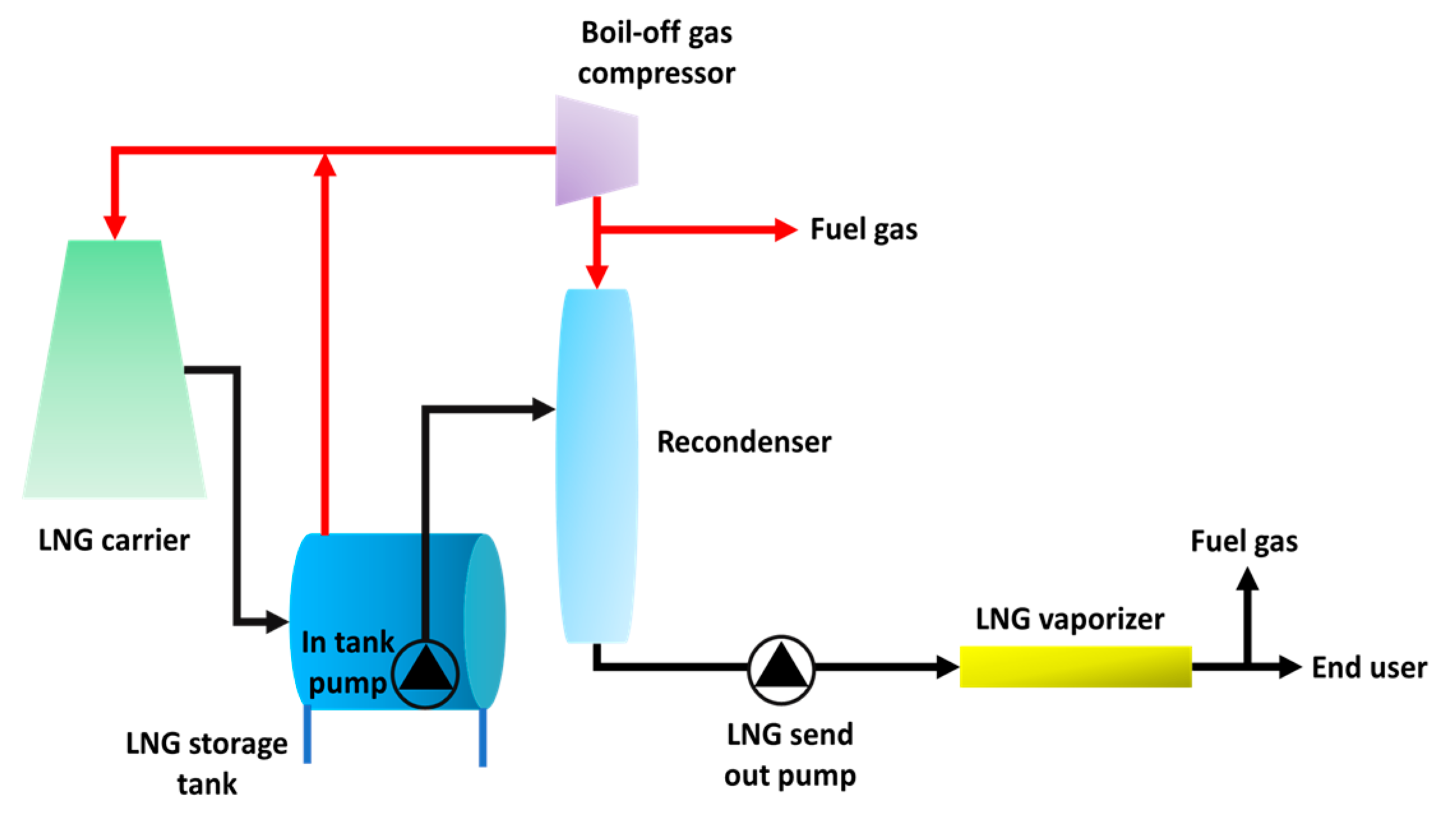
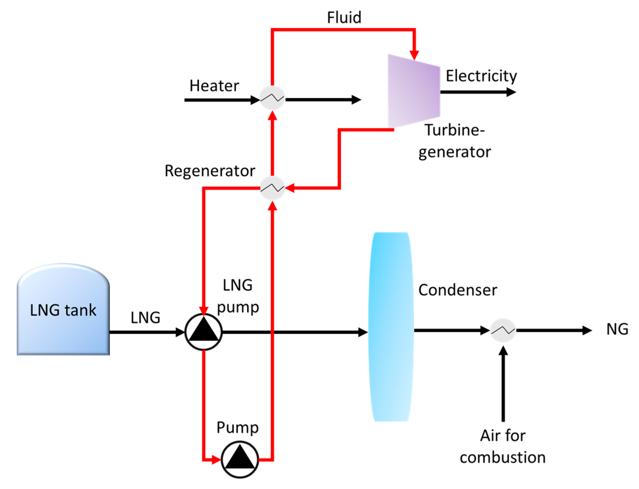
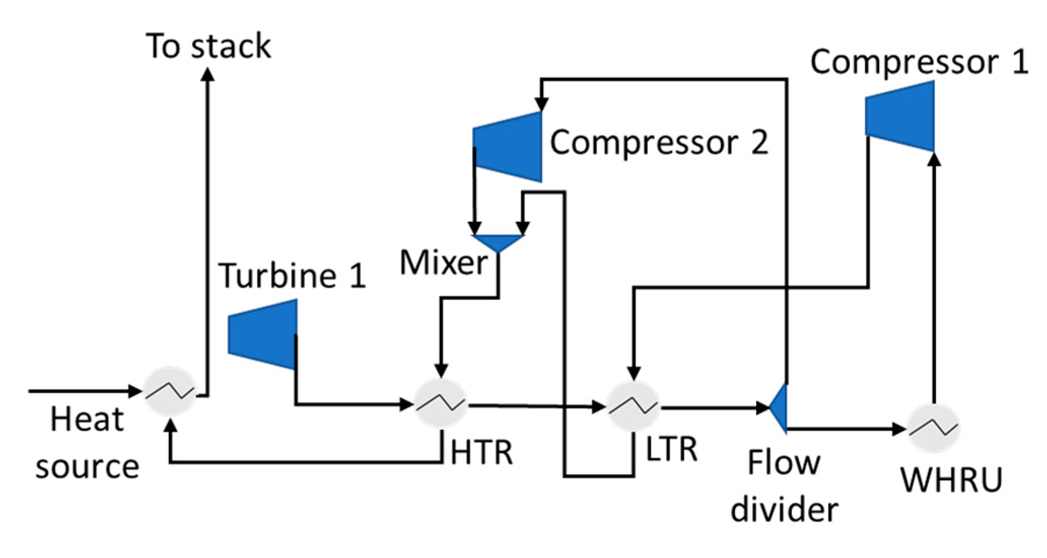
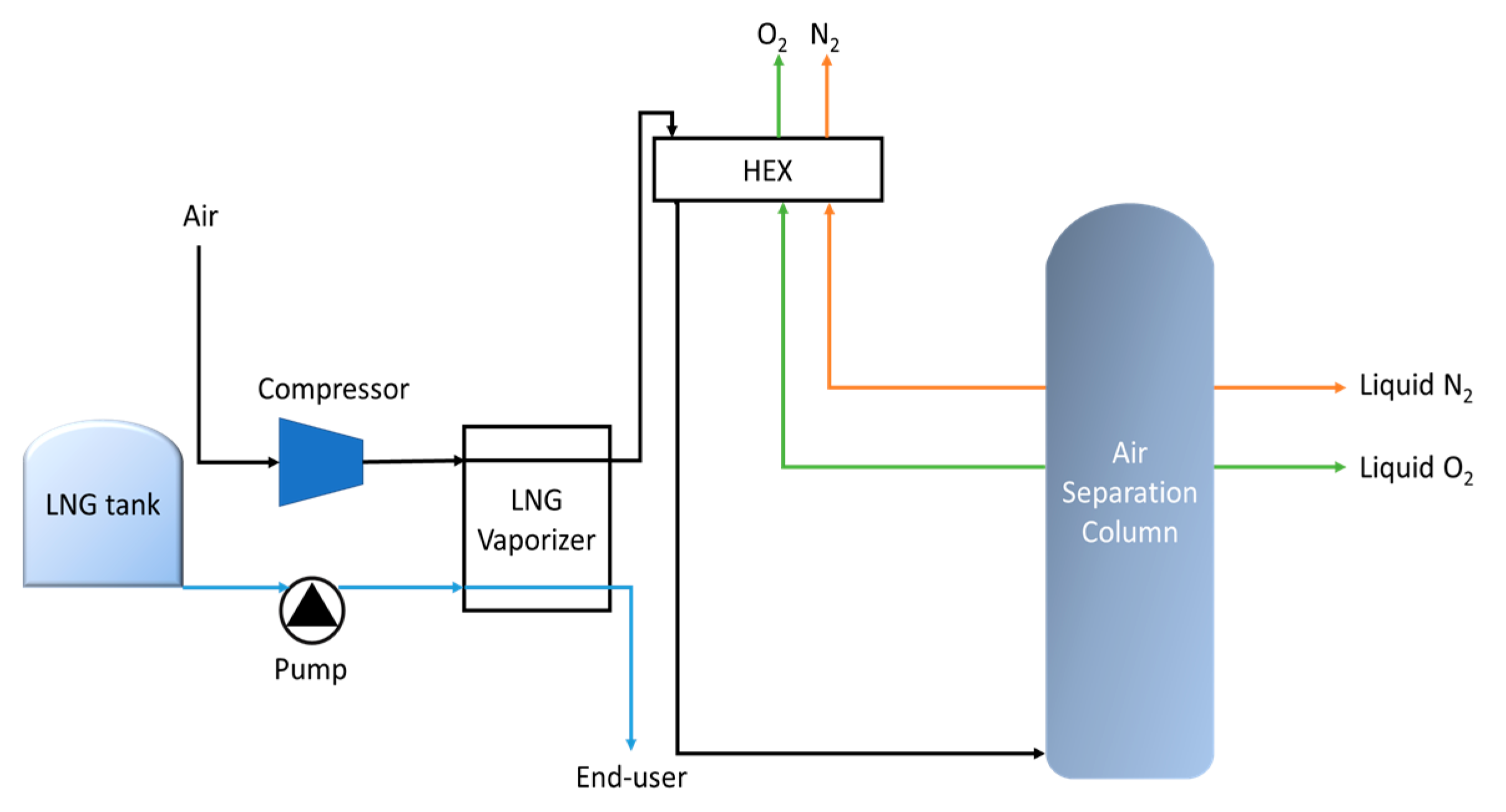
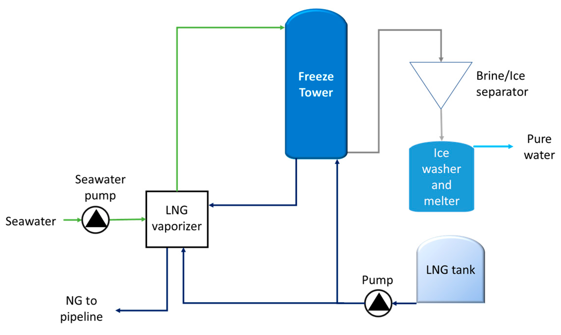
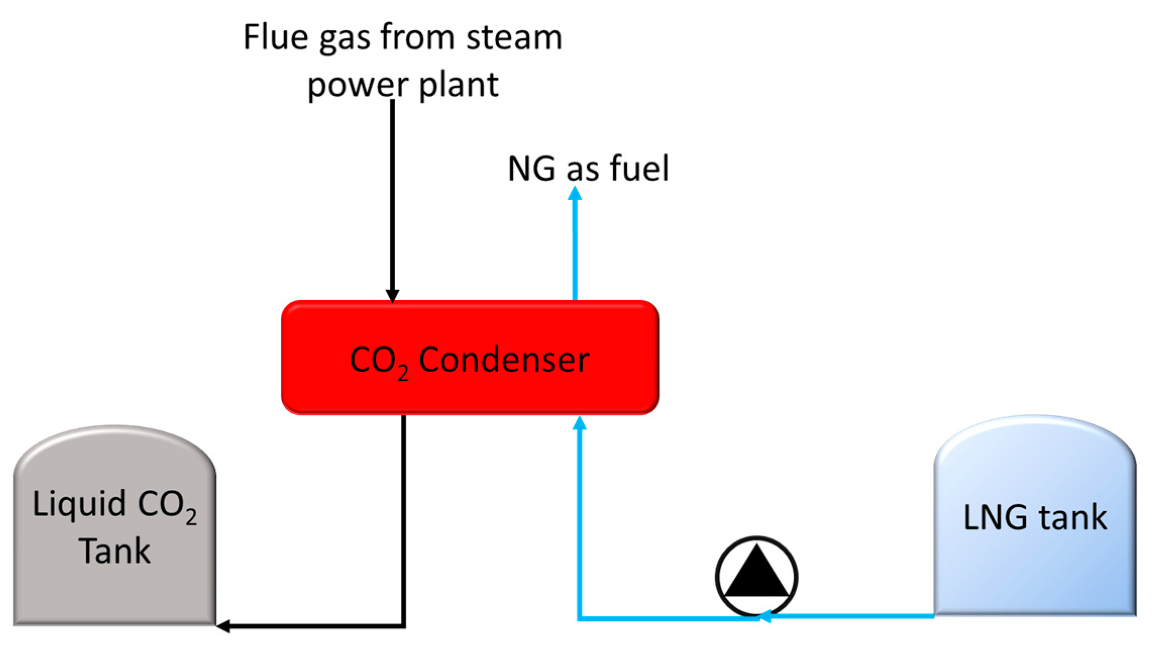
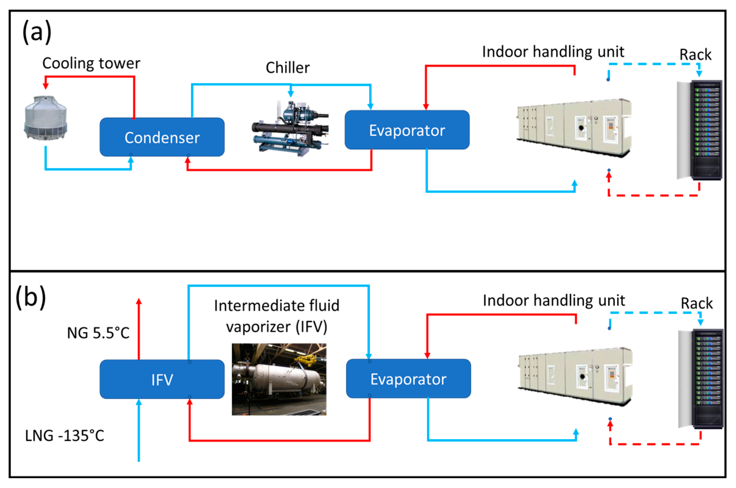
Table 1.
Other works utilizing LNG cold energy for ORC power generation.
| Power Generated (MW) | Working Fluid | References |
|---|---|---|
| 3.773 | R290, R170, and R1150 | [45] |
| 31.67 | R290 | [46] |
| 2.456 | R290, R170, and R1150 | [47] |
| 0.470 | R290 and R1270 | [48] |
| N/A | Binary mixture (R1270 and C2H6) | [49] |
| 9.24 | R290 | [50] |
Table 2.
Other works utilizing LNG cold energy for Brayton cycle in power generation.
| System | References |
|---|---|
| Hydrogen liquefaction with dual-pressure Brayton cycle | [58] |
| Compressor inlet cooling of closed Brayton cycle (CBC) | [59] |
| Hydrogen liquefaction process using reverse Brayton cycle with steam methane reforming | [60] |
Table 3.
Other works on standalone and integrated ASU systems.
| System | Working Fluid | References |
|---|---|---|
| ASU | Neon, argon, oxygen, and nitrogen | [77] |
| LNG powered ship with ASU | Nitrogen and oxygen | [78] |
| ASU | Nitrogen and oxygen | [79] |
| ASU and hydrocarbon recovery | Nitrogen, oxygen, and argon. | [80] |
| ASU with power cycle | Oxygen | [81] |
| ASU | Oxygen | [82] |
Table 4.
Other works on desalination system using cold energy from LNG regasification.
| System | References |
|---|---|
| FD plant integrated with combined gas power cycle plant | [94] |
| FD plant integrated with floating storage regasification unit (FSRU) | [95] |
| Desalination unit integrated with compressed air energy storage (CAES) | [96] |
| Integration of Kalina cycle, Stirling engine, desalination unit, and magnetic refrigeration system | [97] |
| Desalination and power generation | [98] |
Table 5.
Other works on CO2 capture system using cold energy from LNG regasification.
| System | References |
|---|---|
| ASU integrated with CO2 capture | [106] |
| Solar dish collectors with CO2 capture | [107] |
| Power generation with CO2 capture | [108] |
| CO2 capture and storage | [109] |
| Power generation with CO2 capture | [110] |
| Allam cycle power plant with CO2 capture | [111] |
Disclaimer/Publisher’s Note: The statements, opinions and data contained in all publications are solely those of the individual author(s) and contributor(s) and not of MDPI and/or the editor(s). MDPI and/or the editor(s) disclaim responsibility for any injury to people or property resulting from any ideas, methods, instructions or products referred to in the content. |
© 2023 by the authors. Licensee MDPI, Basel, Switzerland. This article is an open access article distributed under the terms and conditions of the Creative Commons Attribution (CC BY) license (https://creativecommons.org/licenses/by/4.0/).
Share and Cite
MDPI and ACS Style
Noor Akashah, M.H.; Mohammad Rozali, N.E.; Mahadzir, S.; Liew, P.Y. Utilization of Cold Energy from LNG Regasification Process: A Review of Current Trends. Processes 2023, 11, 517. https://0-doi-org.brum.beds.ac.uk/10.3390/pr11020517
AMA Style
Noor Akashah MH, Mohammad Rozali NE, Mahadzir S, Liew PY. Utilization of Cold Energy from LNG Regasification Process: A Review of Current Trends. Processes. 2023; 11(2):517. https://0-doi-org.brum.beds.ac.uk/10.3390/pr11020517
Chicago/Turabian StyleNoor Akashah, Muhammad Haziq, Nor Erniza Mohammad Rozali, Shuhaimi Mahadzir, and Peng Yen Liew. 2023. "Utilization of Cold Energy from LNG Regasification Process: A Review of Current Trends" Processes 11, no. 2: 517. https://0-doi-org.brum.beds.ac.uk/10.3390/pr11020517
Note that from the first issue of 2016, this journal uses article numbers instead of page numbers. See further details here.