Article

An Experimental Investigation to Facilitate an Improvement in the Design of an Electromagnetic Continuous Casting Mould

1
Advanced Sustainable Manufacturing Technologies (ASTUTE2020) Project, College of Engineering, Swansea University, Bay Campus, Fabian Way, Swansea SA1 8EN, UK
2
Key Laboratory of National Education Ministry for Electromagnetic Processing of Materials, Northeastern University, Shenyang 110004, Liaoning, China
*
Author to whom correspondence should be addressed.
These authors contributed equally to this work.
Submission received: 23 September 2015 / Accepted: 11 April 2016 / Published: 14 April 2016

Abstract

:
An electromagnetic continuous casting mould designed is proposed with a non-uniform slit distribution structure. This design has aimed to reduce the number of slits so that the mould’s strength is enhanced, whilst maintaining a similar metallurgy effect. In this paper, the metallurgy effect for the designed mould is investigated through the magnetic field distribution along the casting direction, the uniformity feature in the vicinity of the meniscus region, the temperature variation of the molten alloy pool and the mould wall. The results show that the designed mould achieved a similar effect as compared to the original mould; however, the configuration is simplified. This research highlights the topic of mould structure optimization, which would enable the Electromagnetic continuous casting (EMCC) technique to be utilized with greater ease by industry.

1. Introduction

Electromagnetic continuous casting (EMCC) technique was first applied in the aluminum casting process [1,2] with its applications in steel developed in some companies later [3]. In the present research, we pursue two main objectives: to simplify the EMCC mould configuration by reducing the number of slits and to investigate the metallurgy effect for the designed mould.
The study of the EMCC technique is one of interest in the field of liquid metal magnetohydrodynamics (MHD). The instabilities of the interface between the conducting liquid and the insulating atmosphere under the uniform magnetic field has been investigated [4]. The work unveiled that the alternating current (AC) device has advantages compared to the direct current (DC): to obtain good mercury surface stabilization, the essential magnetic flux densities for AC and DC devices are on the order of 0.1 and 1 T, respectively. A threshold for the onset of the instability was determined and this value provided a limit value range on the inducting fluid without incurring the internal undulations and the augmentation of the mass and heat transfer [5]. Furthermore, the value was validated by experiments with the low melting point alloy of lead, tin and bismuth utilized in the experiment. The thermal and dynamic performance of conducting non-Newtonian nanofluid in different cavities has also been investigated in recent years. For the flow between two elliptic cylinders, the results showed that the Nusselt number (ratio of convection heat transfer to conduction rates) increased as the Reyleigh number (ratio of buoyancy to a diffusion velocities) was increased [6]. For the flow past a non-uniform rectangular duct, the effect of the heat and mass transfer was studied by changing the flow rate, etc. [7]. For the flow between two rotating walls, the influence of thermal radiation was investigated [8]: the thickness of the temperature boundary layer decreased as the radiation parameter was increased. The investigation of the nanofluid heat transfer process over a permeable stretching wall revealed that increasing nanoparticle volume fraction decreased the momentum boundary layer thickness [9]. For a fluid flow (Fe3O4-Ethylene glycol) past a channel with a sinusoidal upper wall, the thermal behaviour of an external electric field was discussed [10]. The results showed that the fluid deformation appeared and the heat transfer performance was enhanced, at a different Reynolds number, due to the external electric field. For a flow past a porous diamond shape obstacle, the results showed that the average Nusselt number decreased with increasing Stuart number (ratio of electromagnetic to inertial forces).
Except for the study of the conducting fluid behaviour under a magnetic field, the EMCC mould performance is another concern. Making reference to the work of Garnier [4], the external electric field frequency selection for an AC device was widely discussed. A wide range of frequencies, from 60 Hz [3] (round mould: 0.18 m in diameter) to 100 kHz [11] (square mould: 0.15 m × 0.15 m) were studied by both numerical simulation and experiments. The results showed that, at a high value of frequency, the electromagnetic forming effect was dominant, and, at a low value of frequency, the electromagnetic stirring was dominant. For a rectangular (0.24 m × 0.06 m) mould, the magnetic feature in the mould was discussed for a frequency range from 10 kHz to 50 kHz [12]. How to apply the external magnetic field is another issue which has attracted interest from researchers. An intermittent high frequency (20 kHz) magnetic field was applied through two ways [13]. The first way involved the magnetic field being applied by a given variation frequency, whilst, the second way was that the frequency of the magnetic field was dependent on the frequency of the mould oscillation. The results showed that both of these ways could effectively suppress the oscillation marks. The rectangular, triangle and the sine wave high frequency (18 kHz) amplitude modulated magnetic field has been studied experimentally. The results showed that the sine wave was the best at increasing the intermittent contacting distance, reducing the withdraw resistance and improving the billet’s surface quality. The influence of the multielectromagnetic field, 50 Hz for the top coil and 30 kHz for the bottom coil, on the surface quality of Wood alloy strands was studied [14]. The surface quality of cast strands can be markedly improved by the imposition of a multielectromagnetic field.
From the above short literature review, it is clearly demonstrated that the main advantage of the EMCC technique is that the surface of the strands is smooth enough to be rolled without the scalping process [15,16,17]. The experimental results showed that the depth of the oscillation mark is decreased from 0.6 × 10⁻³ to 1.5 × 10⁻⁴ m [18,19]. However, one of the issues for the EMCC technique in being utilized by industry is its slit-segment structure. Slit-segment structure allows the high frequency magnetic field to permeate the mould and act on the molten alloy. However, this feature destroys the stiffness of the mould and increases the potential risks of accidents during the industrial production. Subsequently, the simplification of the EMCC mould’s configuration, whilst maintaining the same metallurgy effect, is the problem investigated in this paper.
The outline of the present paper is as follows. The basic principles and the experimental facilities are introduced in Section 2. The influence of molten alloy level and the effective acting region are discussed in Section 3.1. In Section 3.2, the magnetic field distribution along casting and the circumference direction is studied. The molten alloy pool and the mould wall temperature variations at different electric power inputs are discussed in Section 4.1 and Section 4.2, respectively. Main conclusions are summarised in Section 5.

2. Basic Principles and the Experimental Facilities

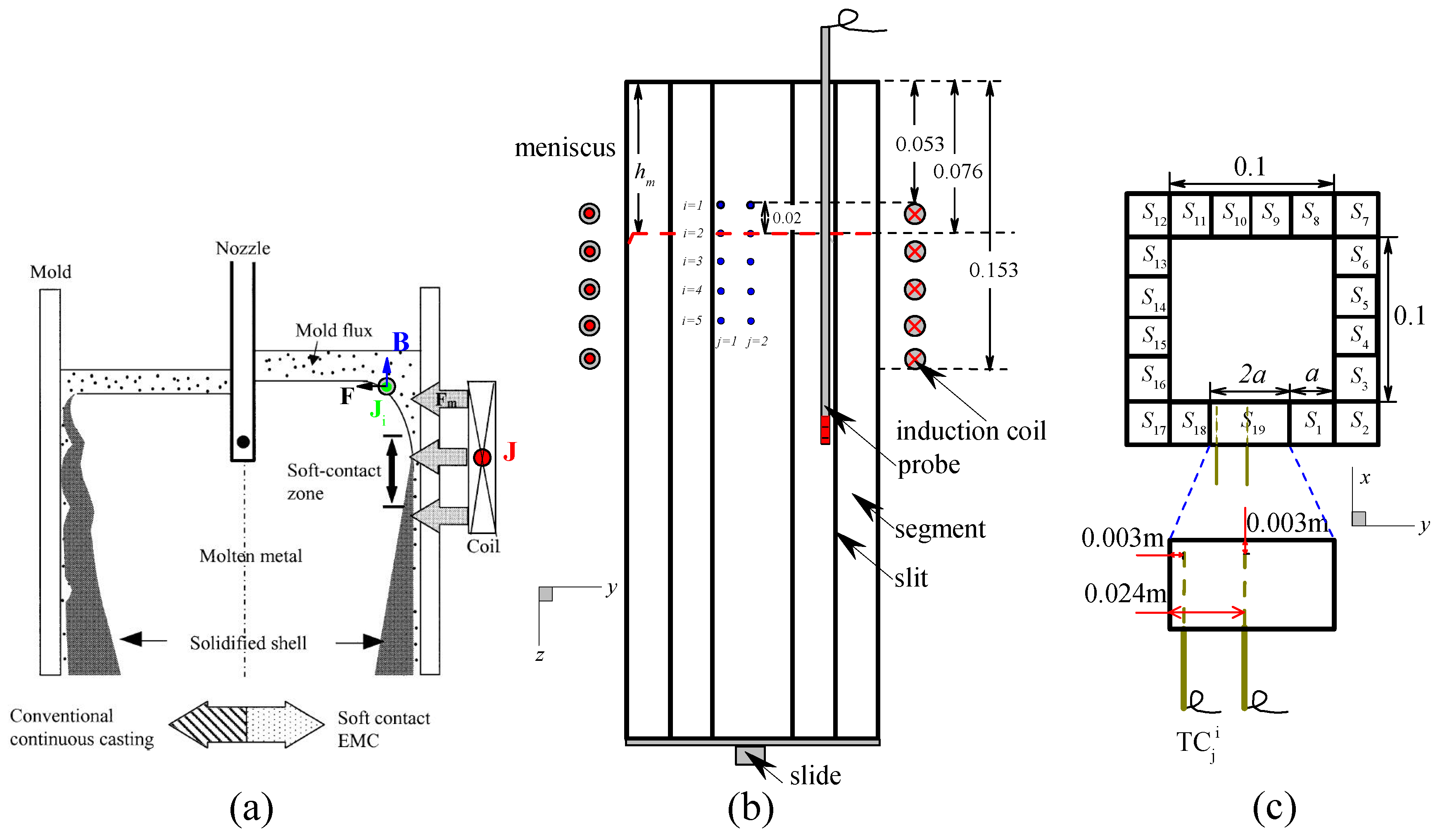
2.1. Basic Principles

Figure 1a shows the basic principles of the EMCC technique.
The EMCC mould is surrounded by an induction coil, which is used as a carrier for the alternating induction current J. With Faraday-Maxwell equation:
× E + B t = 0 ,
where E and B are electric field intensity and the magnetic flux density, respectively. The alternating magnetic field B, with the same frequency of J, is then generated. Simultaneously, the induced current Ji is present in the molten alloy due to Ampere–Maxwell equation:
× B = μ 0 J i + ϵ 0 μ 0 E t ,
where ϵ0, Ji and μ0 are the permittivity of free space, the induced current density and the permeability of the free space, respectively. The displacement current, ϵ 0 μ 0 E t , can be neglected in conducting media (liquid metal, eutectic alloy, etc.) [20]. Equation (2) can be rewritten as:
× B = μ 0 J i .
The molten alloy is then subject to the electromagnetic force F, which is caused by the interaction of B and Ji:
F = J i × B .
The movements of the molten alloy caused by the F can improve the lubricating conditions between the strands and the mould, which allows allowing a higher casting speed resulting in the improvement of the surface quality of the strands and the production rate.

2.2. The Experimental Facilities

The experimental platform is identical to that described in the research of Deng et al. [21]. Figure 1b,c show the schematic representations of the experimental facilities from the front and top view, respectively. The designed EMCC mould is square-shaped (inner dimension: 0.1 m × 0.1 m), with a height of 0.4 m. The mould consists of 19 segments (slits): S1 to S19, as labelled in the figure. Mica slides were placed between the segments in the assembling process with the aim of preventing the large scale loop of induced current along the outer surface of the mould [22]. The height of the slit has the same value as that of the mould. The width of the slit is 0.0005 m, which is acquired from the previous research [12]. The length of segment S1 to S18 is a, where a = 0.0245 m, and the length of S19 is 2a. Large segment (S19) structure design allows us to compare the magnetic feature in the vicinity of S19 to that near the small segment (S9 to S10). Once the relative uniform magnetic field is achieved, the small segments can be replaced by large segments. The number of segments will be reduced, and the stiffness of the mould will increase accordingly. The mould is surrounded by a five-turn hollow copper coil and it is cooled by cooling water. The distance between induction coil top and mould top was 0.053 m. The ISP-200 kW (Hunan Yueci Gaoxin Technology CO., Ltd., Yueyang, China.) supersonic frequency power supply (frequency range: 10–50 kHz) was adopted. The power supply was connected to the induction coil to provide the AC. The generated magnetic field has the same frequency of the applied AC.
A stainless steel, self-cooling cube (0.085 m × 0.085 m × 0.25 m) was used as a simulator of the molten steel in the process of the magnetic field testing. For the magnetic field generated by AC, the magnetic flux density B can be expressed as:
B = B m a x sin 2 π f t ,
where f is the frequency of the AC. A small copper coil is designed to capture the magnetic flux Φ, which is generated by AC. A probe, placed between the simulator and the inner surface of the mould, with small copper coils surrounding the tip is designed. The total magnetic flux through the coils can be expressed as:
Φ = N · S · B cos θ ,
where S, N are the cross sectional area, the turn number of the small coil and the angle between the magnetic flux line and the normal direction of the coil, respectively. By using Equation (6), we then have:
E c = - d Φ d t = - N · S · 2 π f · B m a x · cos θ · sin 2 π f t ,
where Ec is the induced voltage. Ecmax is obtained whist θ = 0o and the effective part of Eeff ( E c m a x / 2 ) can be displayed by a voltage meter. Therefore, the maximum magnetic flux density can be calculated by [23]:
B m a x = E c m a x 2 π · N · S · f .
In the present work, N × S = 1.712 × 10 −4 m2.
The low melting point Pb-16wt%Sn-52wt%Bi alloy was used in the mould thermal performance investigation. The physical properties of the alloy as shown in Table 1. The choice of Pb-Sn-Bi alloy was made because its physical properties are quite similar to steel with the exception of the melting point, which is much lower than that of steel (∼1800 K). This lower melting point has allowed the experiments to be carried out more conveniently. The K-type (NiCr-NiSi) thermal couples were utilized, chosen to allow the capture of temperature variations. Ten thermal couples were embedded in the large segment S19. TC j i denotes different thermal couples, where i ∈ (1–5) and j ∈ (1–2) denote the row and column number, respectively. The location of i = 1 is 0.053 m to the mould top and j = 1 is 0.003 m to the edge of the S19. The distance between the thermal couple tip to the hot surface of the mould is 0.003 m. The distance between different i and j are 0.02 and 0.021 m, respectively. Another thermal couple was placed in the molten metal pool with an intention to capture the variations of the liquid alloy’s temperature. All the temperatures were recorded by the MW100 temperature recording system. All experiments are carried out at a constant electric frequency input (f = 25 kHz).

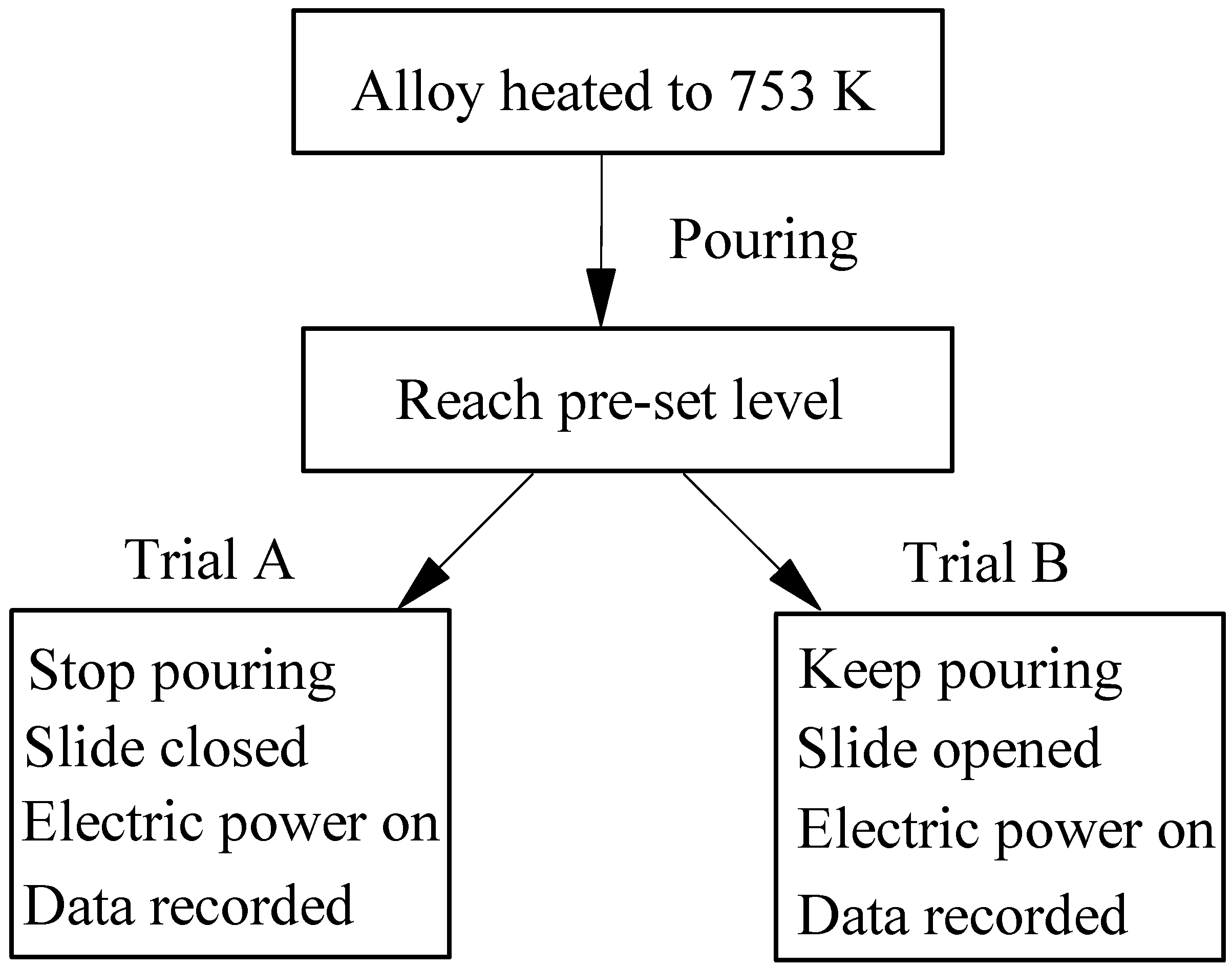
2.3. The Experimental Procedures

The magnetic field feature for the designed mould was first investigated. This stage consisted two steps. For the first step, the influence of the meniscus level (hm) was studied by investigating the magnetic flux density distribution along the casting direction and the variations of the effective acting region (Ref) for different electric power inputs. Ref is first defined. The hm variation was achieved by changing the locations of the stainless steel self-cooling cube. The probe was placed between the simulator and the mould, moving from the top of the mould along a casting direction with an increment 0.01 m or 0.005 m. The magnetic flux density data was obtained. The metal simulator is placed at three locations, relative to the mould top, hm = 0.04, 0.076 and 0.11 m, respectively. Once the optimum hm was selected, the second step was progressed to study the magnetic field uniformity, particularly in the vicinity of the meniscus.
The mould thermal performance was then investigated by studying the temperature variations of the molten alloy pool and the mould. The low melting point alloy was first heated to 753 K and then poured into the mould. The pouring behaviour was stopped once the molten alloy level reached the pre-set location: hm = 0.076 m. After this step, two trials of experiments (trials A and B) were conducted (Figure 2).
For trial A, once the pool temperature decreased to 423 K, the experiment started. The temperatures (pool and mould wall) were recorded from 1 to 60 s. The electric power input P was applied at the beginning of the experiment. For trial B, once the molten alloy level reached hm = 0.076 m, the slide, as shown in Figure 1b, located at the bottom of the mould, was opened to a certain point. The mass of the alloy poured into the mould equalled the mass out so that hm maintained the same value.

3. Magnetic Performance

3.1. Selection of hm

Figure 3 left shows the magnetic flux density distribution along the casting direction (z-axis) at testing location 1# for different electric power inputs P and hm.
The results show that hm affects the location where the maximum value of Bz appears: as hm increases (departing from the mould top), the location of the maximum Bz appears to also depart from the mould top. This is due to the maximum value of Bz usually appearing in the vicinity of the meniscus. Furthermore, as hm increases, the maximum value of Bz decreases: e.g., for P = 64.6 kW, as hm increases from 0.04 m to 0.11 m, the maximum value of Bz decreases by 15.8%. This can be understood as follows, the maximum magnetic flux density usually consists of two main factors: one, the magnetic flux enters from the top of the mould; two, the magnetic flux density permeates from the slits of the mould. As hm increases, the magnetic flux density, which enters from the mould top decreases, and this causes a decrease of the total value of the magnetic flux density.
Figure 3 (right) shows the relationship between the critical magnetic flux density Bc and the effective acting region Ref in the mould at different hm and p values. Here, Bc is defined as the critical or expected magnetic flux density in the production and Ref is defined as the range along the casting direction where the magnitude of Bz is over Bc, as shown in the figure. The results show that Ref decreases as hm is departing from the mould top for a given Bc at a lower value of P, e.g., 11.2 kW. Interestingly, as P increases, e.g., P = 37.8 and 64.6 kW, this trend is found for the higher value of Bc: Bc ≥ 0.4 and 0.5, respectively. This is due to at the higher value of P with lower Bc, the Ref covering most of the region of the mould.
The experimental results indicated when considering both the maximum magnetic flux density and the effective acting region, that the meniscus should be located as close as possible to the mould top, e.g., hm = 0.04 m. However, a small value of hm (free level approaching the mould top) can increase the potential risk of accident during the industrial production process, due to fluctuations of the meniscus, etc. In the present research, hm = 0.076 m is selected.

3.2. Overview of the Magnetic Field

We then turn our attention to the uniformity feature investigation for the designed mould. The uniformity of the magnetic field is a key factor in the initial solidification process. Figure 4 shows the magnetic flux distribution along the casting direction at 64.6 kW (left) and 37.8 kW (right), for the testing location 1# to 8# at hm = 0.076 m.
The results show that for all testing locations and all values of P, the magnetic flux density distribution has a feature of two peaks: the first peak value of Bz appears in the vicinity of the mould top (h = 0 m), and the second peak appears below the meniscus (hm) region. The first peak value is attributed to the part of the magnetic field that comes into the mould through the open top of the mould. The second peak value will influence the initial solidification process of the strands. The steel simulator causes the compression of the magnetic field, which permeates into the mould through the slits, to the inner surface of the mould. The influence of the peak value occurs below the meniscus level. Considering the testing locations 1# and 5#, the two curves in red and blue in the figure, are very close at different h values along the casting direction at different p values considered.
Figure 5 shows the normalized magnetic field at different values of h at the testing locations 1# to 8# for P = 64.6 (left) and 37.8 kW (right).
In the figure, Ba is the defined as the average value of Bz at 1# to 8# at a certain value of h:
B a = n = 1 8 B z n # 8 .
The results show that, as h increases, the uniformity feature presented improves. For the testing locations 1# and 5#, the existence of the uniformity feature is clearly shown for this design of mould, for both electric power inputs considered, especially for the higher p value, for the designed mould. This finding allows us to use the simplified configuration (small number of slits) to achieve the magnetic field obtained by using the original EMCC mould (large number of slits) when considering the magnetic field requirements.

4. Thermal Performance

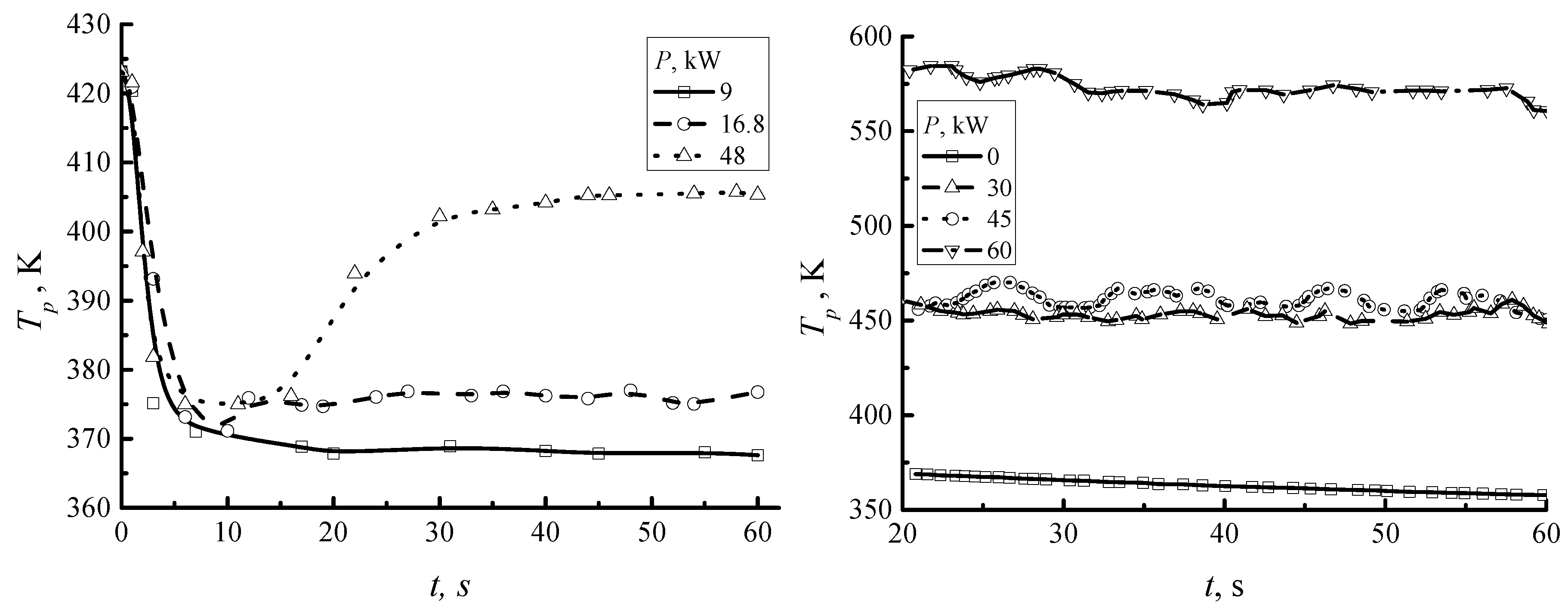
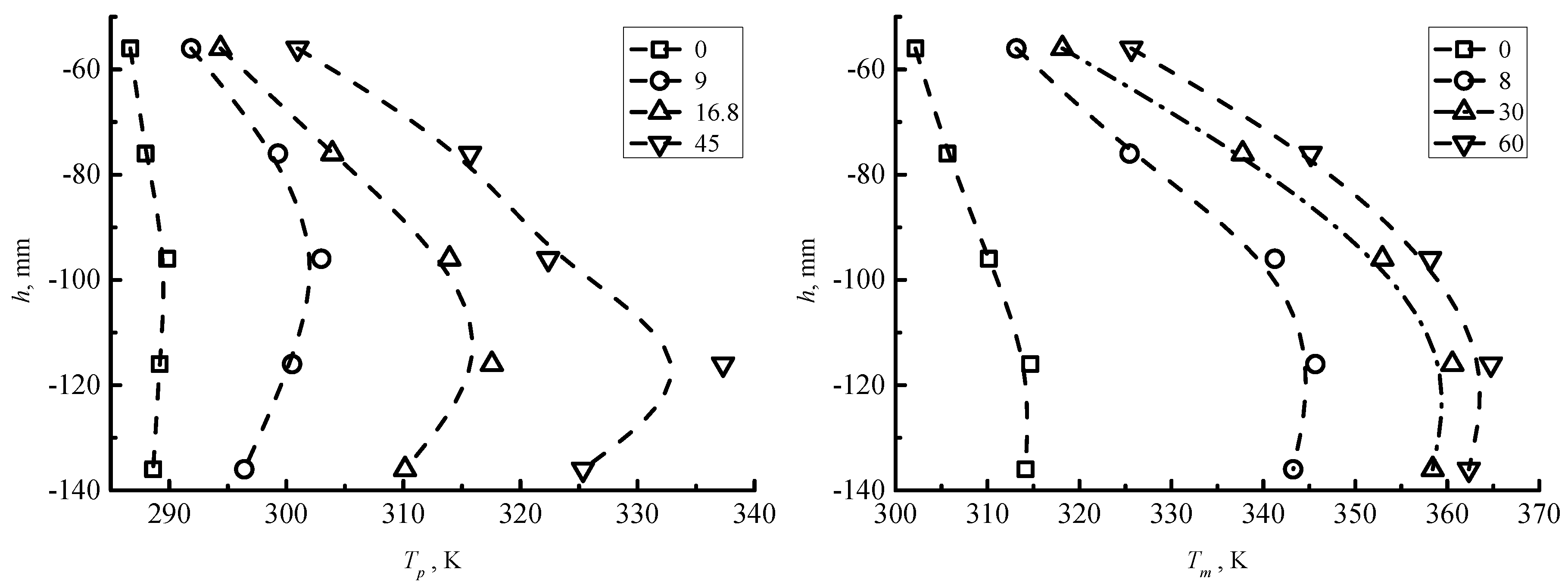
4.1. Alloy Pool Temperature Variation with P

For the thermal performance evaluation for the design mould, we first investigate the temperature variations due to the induced current Ji at different P for trial A and trial B, respectively, as shown in Figure 6.
The temperature is captured by a thermal couple located in the middle of the mould. For trial A, Figure 6 (left), a rapid temperature drop was exhibited for all values of P during 0 to 5 s. This drop attributed to the large temperature gradient between the molten alloy and the mould wall. Even at a higher input value of electric power, 48 kW for instance, the Joule heat cannot compensate for the temperature drop in this time range. From 5 to 20 s, the temperature gradient decreases and the curves become flat. The Joule heat plays a dominant role in the time range from 20 to 60 s. For the low values of electric power input P, the Joule heat only is sufficient to compensate the thermal loss due to the temperature gradient and maintains the Tp at a constant value. As P increases, Tp increases as well: the magnitudes of Tp are 370, 376 and 405 K for the electric power inputs of 9, 16.8 and 48 kW, respectively. Similar results were obtained for trial B. However, the magnitudes of Tp were found to be higher than those for trial A. The is because trial B uses the high temperature molten alloy, and this alloy enhances the overall temperature of the pool.
For both trials, the results also indicated that it is possible to decrease the superheat temperature in the EMCC technique, which is beneficial in saving energy for the process. The results further indicated that the proposed mould’s design maintains the feature in terms of increasing the molten alloy’s temperature.

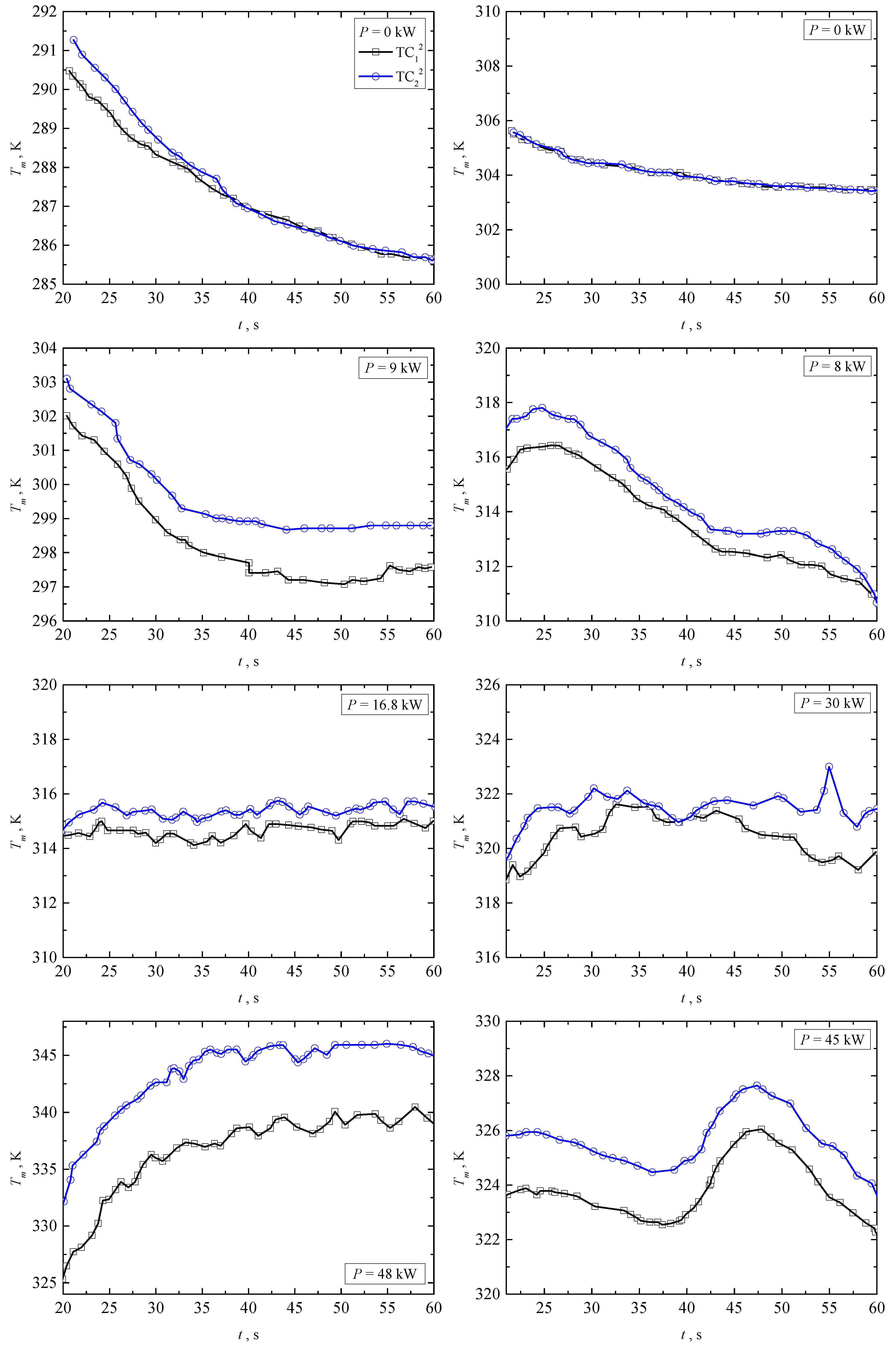
4.2. Mould Wall Temperature with P

Figure 7 shows the mould wall temperature variations at h = 0.076 m for trial A and trial B at different p values.
The temperature data was recorded throughout the experiment. The data between 20 to 60 s has been plotted in order to eliminate the fluctuations which appear in the initial stage (0 ∼ 20 s), as shown in the figure.
It is noticed that for the designed large segment S19, for both trial A and B, the temperature increases as P is increased. This is mainly due to the Joule heat effect. An induced current is generated in both the molten alloy and the mould wall. At a low value of electric power input P, the mould wall temperature decreases with the experimental time t. This is because of the high temperature gradient between the molten alloy and the cold mould wall, which is cooled by water in the segment. As P increases, for both the molten alloy pool and the segment, the magnitude of the induced current in the molten alloy increases. This results in increasing the Joule heat, exhibited by the increase of mould wall temperature. The enhancement of the mould temperature due to Joule heat can also be found in the numerical simulation work of Na et al. [24,25].
The second interesting phenomenon noted is the existence of temperature differences between different locations of the large segment. At P = 0 kW, for both trials, the temperature difference between that found in the vicinity of the large segment’s centre and edge is small. This is attributed to the close and uniform contact between the molten alloy and the mould hot surface along the circumferential direction in the vicinity of meniscus region. As P increases, the temperature difference becomes dominant: the centre region (j = 2) obtains the higher value of the temperature compared to the edge region (j = 1) of S19. This is mainly due to deformation of the molten alloy, which causes discontinuity in the contact between the alloy and the mould hot surface. In the vicinity of the edge of the segment S19 (near slit), the molten alloy is pushed to the centre of the mould and part of the alloy to the centre of the segment by Lorentz force, as shown in Figure 8.
It is shown that the molten alloy in the vicinity of the slit region is pushed departing to the mould hot surface. The “soft-contact” effect is achieved for the designed mould. The deformation of the molten alloy becomes more dominant as P is increased. At the same time, in the vicinity of the centre segment region, high temperature alloy is accumulated. This results in the temperature gradient increasing, and it is represented by the temperature variation of the mould. The temperature difference becomes more dominant as P is further increased. Both of these results indicate that the designed large segment follows the same thermal behaviour as the original small dimension segment configuration. Turning attention to the temperature variation along the casting direction, Figure 9 (left) and (right) show the mould wall temperature distribution along the casting direction at 22 s for different p values for trial A and B, respectively.
The results show that the maximum mould wall temperature appears below the meniscus for both trials. This phenomenon was also observed by Park et al. [19], who found it to be the case for the casting speeds of 1.2, 1.5 and 1.8 m/min, respectively. The location where the maximum temperature appears moves to the outlet of the mould as P is increased. This is due to an increase of Lorentz force: the height of the meniscus increases and this results in the initial solidification point departing from the mould top. The results show that the designed EMCC mould maintains the thermal performance and achieves the same metallurgy effect compared with the original mould.

5. Conclusions

A full segment type of electromagnetic continuous casting mould (0.1 m × 0.1 m × 0.4 m) was designed and manufactured. The mould was designed with a non-uniform slit distribution, with the intention of simplifying the structure to enhance the mould stiffness, beneficial when using the EMCC technique in industry. To ensure the designed mould maintains the required metallurgy effects, a series of experiments were conducted, focusing on the magnetic feature and thermal performance. The main conclusions can be summarised as follows:
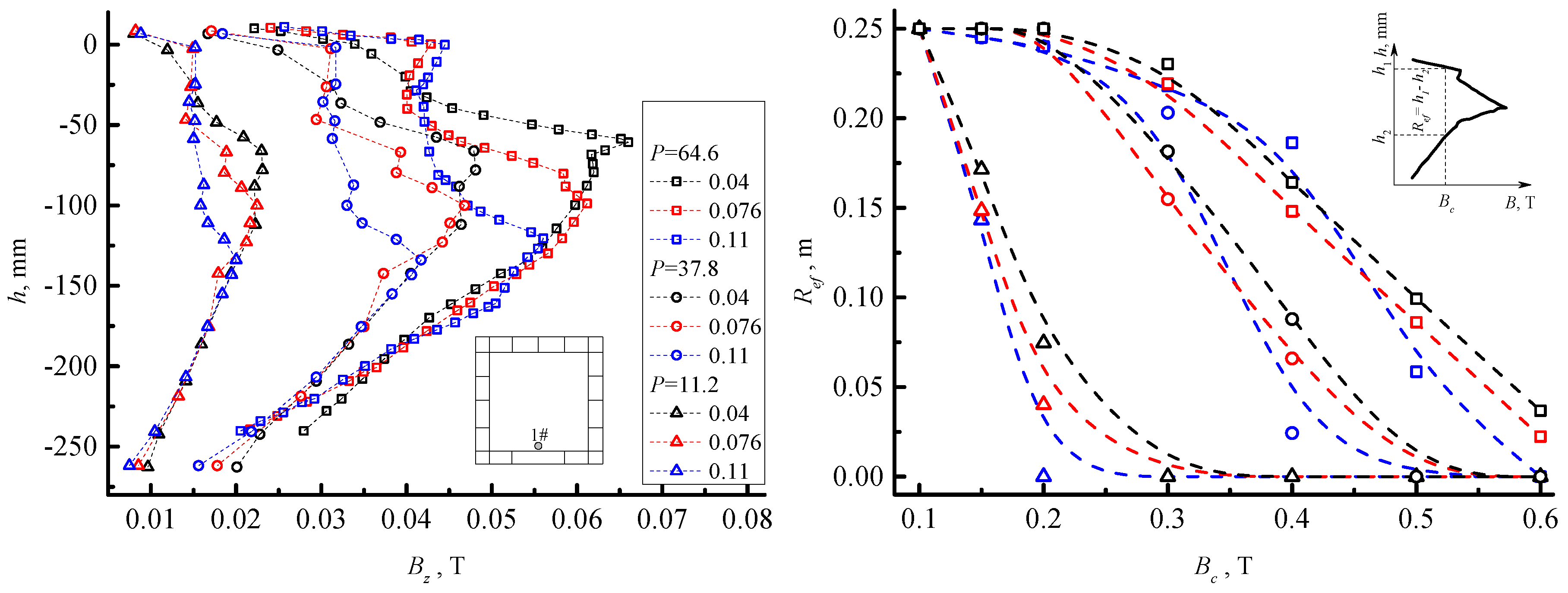
  • the effective acting region Ref for the critical (expected) magnetic field Bc was defined. Ref highly depends on the external magnetic field and the relative location between the induction coil and the meniscus. Ref influence will be dominant whilst the liquid region in the mould is large.
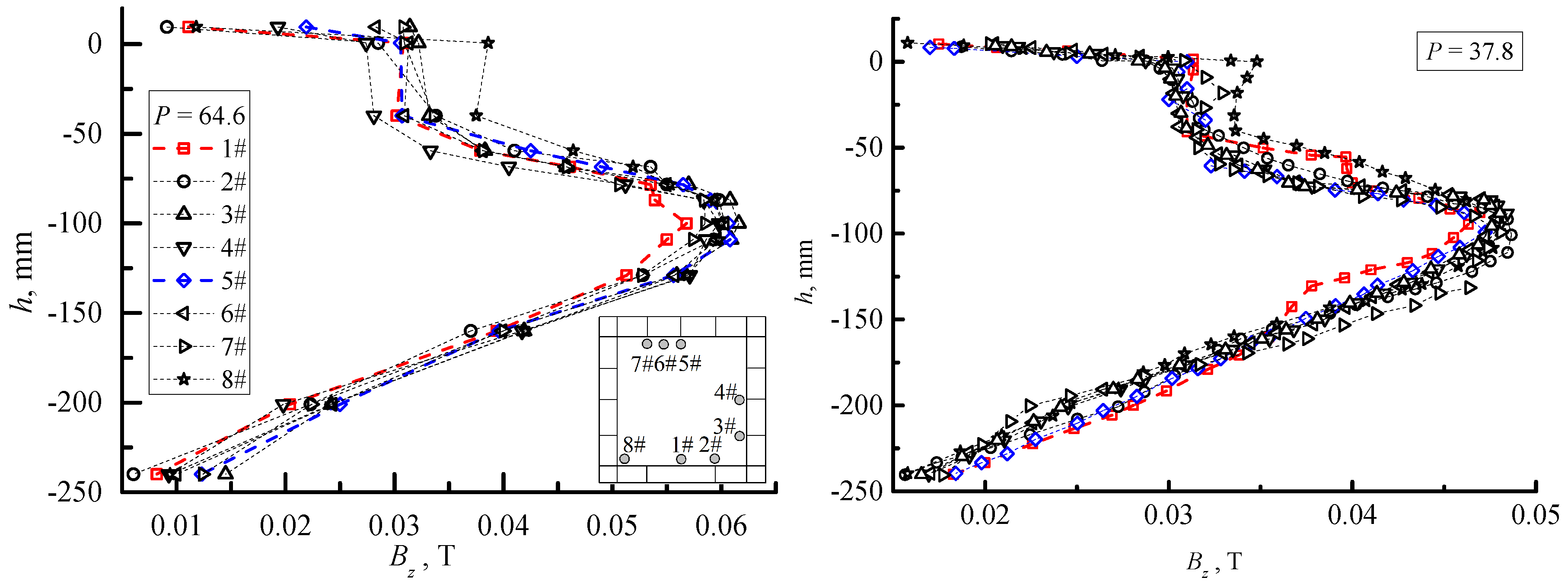
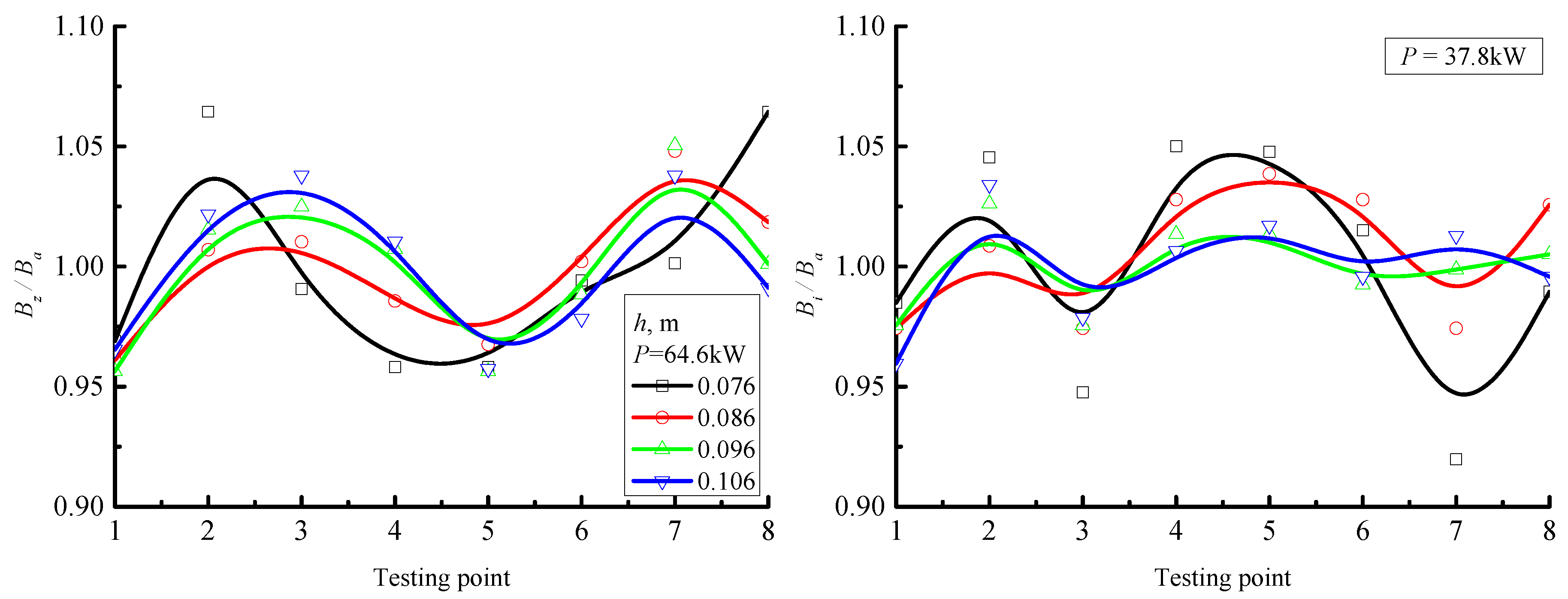
  • Uniformity of the magnetic field was achieved along the casting direction and in the circumferential direction, in the vicinity of the meniscus.
  • The temperatures of the molten alloy pool and mould wall increase with increasing electric power input P. The temperature in the vicinity of the segment centre presents a higher value than that near the edge, especially at a high value of P.
  • Along the casting direction, the location where the maximum temperature value appears moves towards the outlet of the mould as P is increased.
These conclusions indicate that the newly designed mould will not vary the metallurgy effects, and it is possible to reduce the number of the segments of the mould to simplify the configuration.

Acknowledgments

The authors gratefully acknowledge financial support from the National Nature Science Foundation of China (Grant 50834009), the Key grant Project of China Ministry of Education (Grant 311014), the 111 Project of China (Grant B07015) and the National Natural Science Foundation of China (51474065). The authors are grateful to Dr. Jennifer Thompson for her proofreading. Additionally, the authors would also like to thank the referees for their work which has contributed to this paper.

Author Contributions

Lintao Zhang, Anyuan Deng and Engang Wang and Johann Sienz contributed equally to this work.

Conflicts of Interest

The authors declare no conflict of interest.

References

  1. Vives, C. Electromagnetic refining of aluminum alloys by the CREM process: Part I. working principle and metallurgical results. Metall. Mater. Trans. B 1989, 20, 623–629. [Google Scholar] [CrossRef]
  2. Vives, C.; Ricou, R. Experimental study of continuous electromagnetic casting of aluminum alloys. Metall. Mater. Trans. B 1985, 16, 377–384. [Google Scholar] [CrossRef]
  3. Toh, T.; Takeuchi, E.; Hojo, M.; Kawai, H.; Matsumura, S. Electromagnetic control of initial solidification in continuous casting of steel by low frequency alternating magnetic field. ISIJ Int. 1997, 37, 1112–1119. [Google Scholar] [CrossRef]
  4. Garnier, G.; Moreau, R. Effect of finite conductivity on the inviscid stability of an interface submitted to a high-frequency magnetic field. J. Fluid Mech. 1983, 127, 365–377. [Google Scholar] [CrossRef]
  5. Echeale, E.J.; Melcher, J.R. Instability of a planar liquid layer in an alternating magnetic field. J. Fluid Mech. 1982, 127, 27–40. [Google Scholar]
  6. Sheikholeslami, M.; Ellahi, R.; Hassan, M.; Soleimani, S. A study of natural convection heat transfer in a nanofluid filled enclosure with elliptic inner cylinder. Int. J. Numer. Methods Heat Fluid Flow 2014, 24, 1906–1927. [Google Scholar] [CrossRef]
  7. Ellahi, R.; Bhattu, M.M.; Vafai, K. Effect of heat and mass transfer on peristaltic flow in a non-uniform rectangular duct. Int. J. Heat Mass Transf. 2014, 71, 706–719. [Google Scholar] [CrossRef]
  8. Sheikholeslami, M.; Davood, D.G.; Javed, M.Y.; Ellahi, E. Effect of thermal radiation on magnetohydrodynamics nanofluid flow and heat transfer by means fo two phase model. J. Magn. Magn. Mater. 2015, 374, 36–43. [Google Scholar] [CrossRef]
  9. Sheikholeslami, M.; Ellahi, R.; Ashorynejad, H.R.; Domairry, G.; Hayat, T. Effect of heat transfer in flow of nanofluids over a permeable stretching wall in a porous medium. J. Comput. Theor. Nanosci. 2014, 11, 486–496. [Google Scholar] [CrossRef]
  10. Sheikholeslami, M.; Ellahi, E. Electrohydrodynamic nanofluid hydrothermal treatment in an enclosure with sinusoidal upper wall. Appl. Sci. 2015, 5, 294–306. [Google Scholar] [CrossRef]
  11. Nakata, H.; Inoue, T.; Mori, H.; Murakami, T.; Mominami, T. Improvement of billet surface quality by intra-high-frequency electromagnetic casting. ISIJ Int. 2002, 42, 264–272. [Google Scholar] [CrossRef]
  12. Zhang, L.; Wang, E.; Deng, A.; He, J. Numerical simulation of influence of slit parameters of soft-contact mould on the distribution of magnetic field. Chin. J. Process Eng. 2006, 6, 713–717. [Google Scholar]
  13. Li, T.; Sassa, K.; Asai, S. Surface quality improvement of continuously cast metals by imposing intermittent high frequency magnetic field and synchronizing the field with mould oscillation. ISIJ Int. 1995, 36, 410–416. [Google Scholar] [CrossRef]
  14. Li, T.; Li, X.; Zhang, Z.; Jin, J. Effect of multielectromagnetic field on meniscus shape and quality of continuously cast metals. Ironmak. Steelmak. 2006, 31, 57–60. [Google Scholar] [CrossRef]
  15. Bermudez, A.; Muniz, M.C.; Sslgado, P. Asymptotic approximation and numerical simulation of electromagnetic casting. Metall. Mater. Trans. B 2003, 34, 83–91. [Google Scholar] [CrossRef]
  16. Evans, J.W. The Use of Electromagnetic Casting for Al Alloys and Other Metals. JOM 1995, 47, 38–41. [Google Scholar] [CrossRef]
  17. Evans, J.W. Mathematical modeling of meniscus profile and melt flow in electromagnetic casters. Metall. Mater. Trans. B 1988, 19, 397–408. [Google Scholar]
  18. Park, J.; Jeong, H.; Kim, H.; Kim, J. Laboratory scale continuous casting of steel billet with high frequency magnetic field. ISIJ Int. 2002, 42, 385–391. [Google Scholar] [CrossRef]
  19. Park, J.; Kim, H.; Jeong, H.; Kim, G.; Cho, M.; Chung, J.; Yoon, M.; Kim, K.; Cho, J. Continuous casting of steel billet with high frequency electromagnetic field. ISIJ Int. 2003, 43, 813–819. [Google Scholar] [CrossRef]
  20. Moreau, R. Magnetohydrodynamics; Kluwer Academic Publisher: Dordrecht, The Netherlands, 1990. [Google Scholar]
  21. Deng, A.; Xu, X.; Wang, E.; Zhang, L.; Zhang, X.; He, J. Experimental research on round steel billet electromagnetic soft contact continuous casting process. Iron Steel 2009, 44, 33–37. [Google Scholar]
  22. Fort, J.; Garnich, M.; Klymyshyn, N. Electromagnetic and thermal-flow modeling of a cold-wall crucible induction melter. Metall. Mater. Trans. B 2005, 36, 141–152. [Google Scholar] [CrossRef]
  23. Ren, Z.; Dong, H.; Deng, K.; Jiang, G. Influence of high frequency electromagnetic field on the initial solidification during electromagnetic continuous casting. ISIJ Int. 2001, 41, 981–985. [Google Scholar] [CrossRef]
  24. Na, X.; Xue, M.; Zhang, X.; Gan, Y. Numerical simulation of heat transfer and deformation of initial shell in soft contact continuous casting mould under high frequency electromagnetic field. J. Iron Steel Res. Int. 2007, 14, 14–21. [Google Scholar] [CrossRef]
  25. Na, X.; Zhang, X.; Gan, Y. Mathematical Analysis and Numerical Simulation of High Frequency Electromagnetic Field in Soft Contact Continuous Casting mould. ISIJ Int. 2002, 42, 974–981. [Google Scholar] [CrossRef]
Figure 1. (a): basic principles of electromagnetic continuous casting technique [18]; (b) and (c) are the schematic representations of the experimental facilities from the front view and the top view, respectively.
Processes 04 00014 g001
Figure 2. Experiment procedures for trials A and B.
Processes 04 00014 g002
Figure 3. (Left): Variations of the magnetic flux density Bz along the casting direction at testing location 1# for different hm and P. (Right): the critical magnetic flux density Bc vs. the effective acting region Ref. The legends are the same as that on the left.
Processes 04 00014 g003
Figure 4. Magnetic flux density distribution along the casting direction at different testing locations for P = 64.6 kW (left) and 37.8 kW (right) at hm = 0.076 m.
Processes 04 00014 g004
Figure 5. Magnetic flux density distribution at different level of h for different testing locations for P = 64.6 kW (left) and 37.8 kW (right).
Processes 04 00014 g005
Figure 6. Variations of the molten alloy temperature at different P for trial A (left) and trial B (right).
Processes 04 00014 g006
Figure 7. Mould wall temperature variations at different P at h = 0.076 m for trial A (left) and trial B (right).
Processes 04 00014 g007
Figure 8. The deformation of the molten alloy.
Processes 04 00014 g008
Figure 9. Temperature distribution along casting direction of mould wall at t = 22 s for different P for trial A (left) and trial B (right), respectively.
Processes 04 00014 g009
Table 1. The material properties of low melting point Pb-16wt%Sn-52wt%Bi alloy.
Melting PointDensityViscosityElectric ConductivityMagnetic Permeability
(K)(kg/m3)(S/m)(m2/s)(H/m)
368.1595001.1 × 1063.4 × 10−74π × 10−7

