Control Strategy for Inverter Air Conditioners under Demand Response


Key Laboratory of Smart Grid of Ministry of Education, Tianjin University, Tianjin 300072, China
*
Author to whom correspondence should be addressed.
Processes 2019, 7(7), 407; https://0-doi-org.brum.beds.ac.uk/10.3390/pr7070407
Submission received: 26 May 2019
/
Revised: 15 June 2019
/
Accepted: 25 June 2019
/
Published: 1 July 2019
(This article belongs to the Special Issue Energy Storage System: Integration, Power Quality, and Operation)
Abstract
:Air conditioning loads are important resources for demand response. With the help of thermal energy storage capacity, they can reduce peak load, improve the reliability of power grid operations, and enhance the emergency capacity of a power grid, without affecting the comfort of the users. In this paper, a virtual energy storage model for inverter air conditioning loads, which reflects their operating characteristics and is more conducive to practical application, is established. Two parts are involved in the virtual energy storage model: An electrical parameter part, based on the operating characteristics, and a thermal parameter part, based on the equivalent thermal parameter model. The control function and restrictive conditions of the virtual energy storage are analyzed and a control strategy, based on virtual state-of-charge ranking, is proposed. The strategy controls the inverter air conditioners through re-assigning indoor temperature set-points within the pre-agreed protocol interval and gives priority those with a higher virtual state of charge. As a result, electric power consumption is reduced while the temperature remains unchanged, so that a shortage in the power system can be compensated for as much as possible, while the comfort of users is guaranteed. Simulation and example analyses show that the strategy is effective in controlling air conditioning loads. Additionally, the influences of load reduction target magnitude and communication time-step on the performance of the control strategy are analyzed.
1. Introduction
Renewable energy sources, such as wind and solar power, have a high degree of unpredictability and time-variability [1]. The increasing penetration of renewable power generation in electric power systems makes it even more costly and difficult for power systems to maintain a balance between supply and demand. Furthermore, energy generation by conventional generators has become increasingly insufficient to meet the needs of system regulation [2]. Demand response technology is one of the core technologies of a smart grid, which can effectively restrain the random fluctuations of power flow, alleviate the tension between supply and demand, improve the efficiency of system operations, and promote energy saving and emissions reduction [3]. Therefore, it has become increasingly important to utilize flexibility on the demand side of power systems.
The rapid development of two-way communications technology and advanced metering infrastructures in smart grid has created new opportunities for the implementation of demand-side management in the power industry [4,5]. Demand response can solve the problem of mismatching between supply and demand with relatively low cost, which is of great significance in facilitating the integration of new energy sources and reducing power shortages [6,7]. The popularization of advanced metering infrastructures has made possible the implementation of control strategies for inverter air conditioner loads and the large-scale application of trunked dispatching. In [8], an architecture and supporting algorithms were proposed for privacy-preserving thermal inertial load management as a service provided by the load serving entity (LSE). It focused on an LSE managing a population of its customers’ air conditioners, and proposed a contractual model where the LSE guarantees quality of service to each customer, in terms of keeping their indoor temperature trajectories within respective bands around the desired individual comfort temperatures.
Besides the many other flexible loads, such as pool pumps [1,9,10], air conditioning loads are an important type of demand response resources with great potential. According to incomplete statistics, air conditioning loads accounted for 30–40% of the peak load in summer [11] in China. In certain cities, such as Beijing, this number reached 52%, with an increasing trend year by year. Buildings with inverter air conditioners can act as virtual energy storage (VES), because of their thermal energy storage capability and the fact that the human body has no obvious response to temperature changes within a certain range. In [12], it was experimentally proved that the demand response of air conditioners is effective. Under the premise of ensuring the basic comfort of users [13], air conditioners can be equivalent to a load resource with flexible dispatch capability, which has huge potential [14]. Effective management of air conditioning loads during peak periods through reasonable control means is conducive to reducing power shortages and optimizing power consumption modes.
There have been a number of studies conducted regarding demand response from air conditioners at different levels, including both household [15,16] and aggregation levels. Both simulation and experimental studies [12] have been conducted. The air conditioners considered included split air conditioners and central air conditioners [17]. This paper focuses on the load reduction services from aggregated split inverter air conditioners.
Most existing studies regarding the demand response from air conditioners have focused on constant-speed air conditioners. However, in recent years, inverter air conditioners have been favored by users for their advantages of energy saving and comfort. With the guidance of national energy saving and emissions reduction policies in many countries, such as China, the number of installed inverter air conditioners keeps growing, accounting for a significant share of total air conditioners installed. Therefore, it is necessary to study their participation in demand response [18].
In this context, some preliminary research has been conducted regarding the demand response from inverter air conditioners, which could be further classified into two categories: The first category of studies explored the building thermodynamic model of inverter air conditioners. The equivalent thermal parameter (ETP) model has been widely used as the basis for further control. In [19], based on a first-order ETP model, the VES model of a building with air conditioners was established considering comfort level, and a series of VES parameters, such as rated capacity, rated power, and charging and discharging times were derived. However, in [13], the electric power of air conditioners was taken as a constant power input, lacking an in-depth analysis of the electrical parameters of air conditioners; therefore, it could not describe the influence of the state change of air conditioning loads on the power grid. In [19], a high-precision model reflecting the different operating conditions of electric water heaters was proposed; however, due to the limitation of calculation, the model was only suitable for small-scale regulation, and could not be applied to a power grid cluster dispatch. Compared to existing studies, such as [13,19], this paper establishes a VES model for inverter air conditioning loads which is more conducive to practical application. Two parts are involved in the VES model: An electrical parameter part, based on the operating characteristics of inverter air conditioning loads, and a thermal parameter part, based on the equivalent thermal parameter model.
The second category of studies explored load reduction in inverter air conditioners to compensate for power shortages. In [20], direct load control was considered for the purpose of load reduction, but a control strategy for air conditioning loads was not given. In [21,22], direct load control based on a state-priority queue control method was proposed, but its stability heavily depended on the diversity of load-states, which is easily destroyed. Ninagawa et al. established a neural network model, based on practical operational data of inverter air conditioners, for simulating their load reduction responses [23]. The practical communication environment was also emulated. Compared to these studies [20,21,22,23], the present study has the following novel contributions: (1) Virtual state-of-charge (VSOC) is defined to reflect the energy storage level of a VES, based on which a VSOC-priority strategy is proposed to control inverter air conditioners to provide demand response services; (2) the electric power of inverter air conditioners is controlled at a level where the corresponding heating output exactly compensates for the heat loss, so that the indoor temperature will not go beyond a set limit during control; and (3) the impact of the shape and magnitude of load reduction targets and the length of communication time-step on the control performance is investigated.
This paper investigates how large amounts of inverter air conditioners can be modeled and controlled to provide demand response services for power systems. It is assumed that power utility companies will recruit customers with inverter air conditioners installed and, further, install necessary communication and control devices to aggregate the inverter air conditioners and enable the control strategy proposed in this paper. Specifically, in this paper, inverter air conditioners are modeled as VES, including electrical parameter and thermal parameter parts. Based on the VES model, a VSOC-priority strategy is proposed to control the inverter air conditioners in order to provide demand response services. Finally, the performance of the proposed control strategy is verified, with the impact of the shape and magnitude of load reduction targets and the length of communication time-step assessed.
2. Load Modeling of Inverter Air Conditioners
In this section, an inverter air conditioner is modeled as a VES. First, the electrical quantity relation regarding the inverter air conditioner is presented. Then, the thermal and electrical parts of the VES model are described. Finally, the VES model for inverter air conditioners is summarized.
2.1. Electrical Quantity Relation
An inverter air conditioner adjusts the speed of the compressor by adjusting the power supply frequency through a frequency converter to realize the control of compressor power. As a result, inverter air conditioners can achieve smooth control of temperature, low power loss, and good user comfort. In the temperature maintenance stage, the active power consumption of an inverter air conditioner is only about 30% of a fixed-speed air conditioner [24]. Generally speaking, the electric power consumption of an inverter air conditioner is linearly related to frequency [25,26],
where Pelectrical represents the heating rate of an inverter air conditioner, in kW; PIac_rated represents the electric power of the inverter air conditioner, in kW; the constant coefficients a, b, c, and d depend on the type and internal parameters of the air conditioner; and f(t, ΔT) indicates that operating frequency, which is a function of the time and temperature difference between the room temperature and the set temperature.
The relationship between the electric power and heating rate of the inverter air conditioner can be obtained as follows:
where η = a/c represents the energy efficiency ratio of the inverter air conditioner.
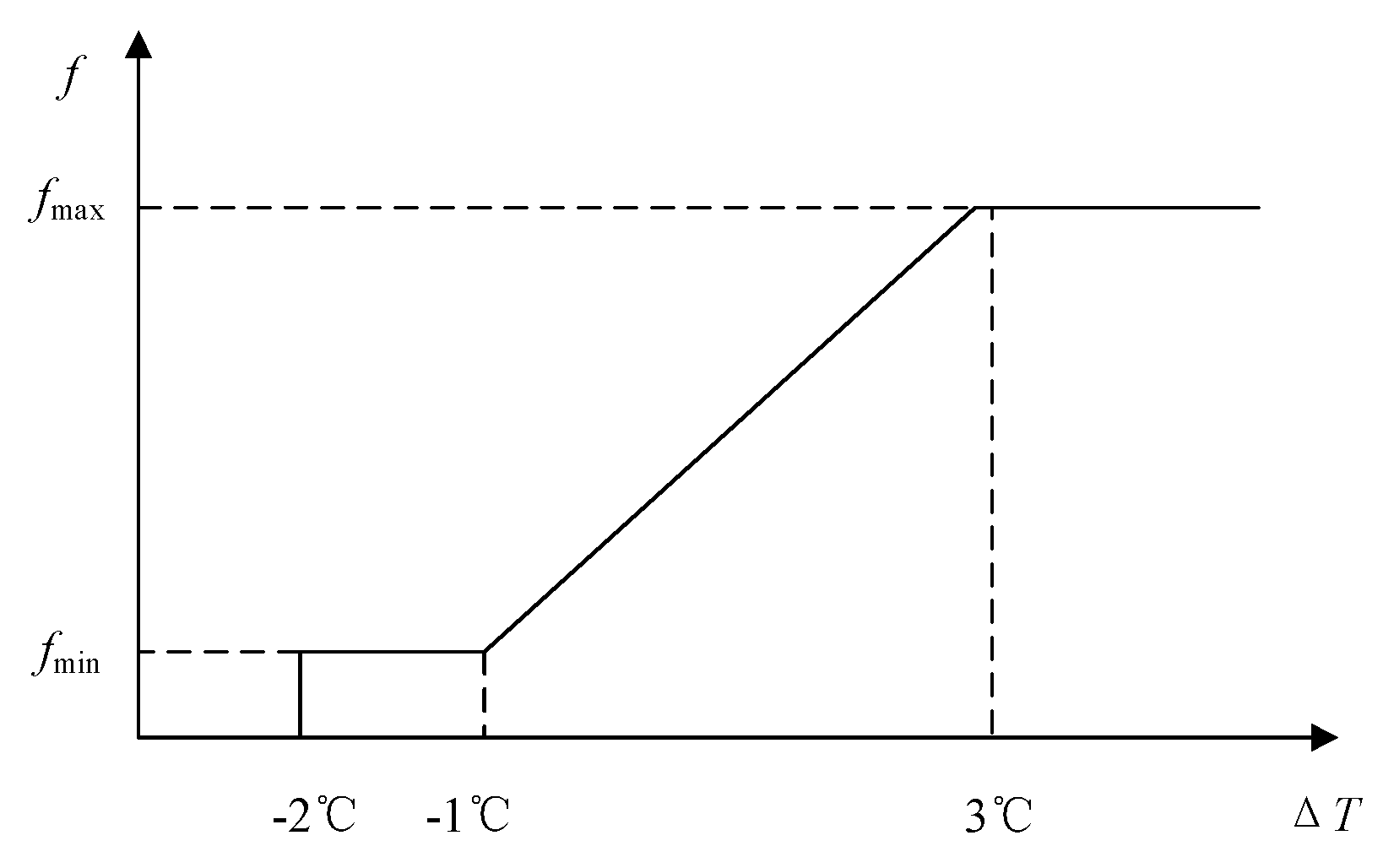
The relationship between the temperature difference and the operating frequency is shown in Figure 1. In practical applications, the temperature difference seldomly appears as a negative value, so, when 0 °C < ΔT ≤ 3 °C, the operating frequency is expressed as
2.2. Thermal Parameter Part
The first-order ETP model is adopted [27] to describe the thermodynamics of a room with an inverter air conditioner, expressed as follows:
Based on (5), the relationship between the room temperature Tin and the VES power supply Pele (i.e., the heating rate of inverter air conditioner) can be obtained [27] as
where Tint and Tint+1, respectively, represent the internal temperature of the room at times t and t + 1, in °C; Toutt and Toutt+1, respectively, represent the external environment temperature at t and t + 1, in °C; Pele is the VES power supply (heating rate of inverter air conditioner); R1 represents the thermal resistance of energy transfer between the interior and exterior environment of a room, in °C/W; Ce represents the equivalent heat capacity in a room; Δt is the time-step between t and t + 1; and S represents the switching function.
The charging and discharging time of the VES is as follows:
2.3. Electrical Parameter Part
The electrical part of the inverter air conditioner represents the relationship between the input heating power and the electric power, and the influence of load-state change on the grid power.
Assume that the capacity of the community transformer is sufficient, the voltage of the external large power grid is stable, and the influence of reactive power change of the inverter air conditioner is ignored. Then, the electrical parameter part of the inverter air conditioner model is
where SIac(t) represents the switching state of the inverter air conditioner.
2.4. VES Model of an Inverter Air Conditioner
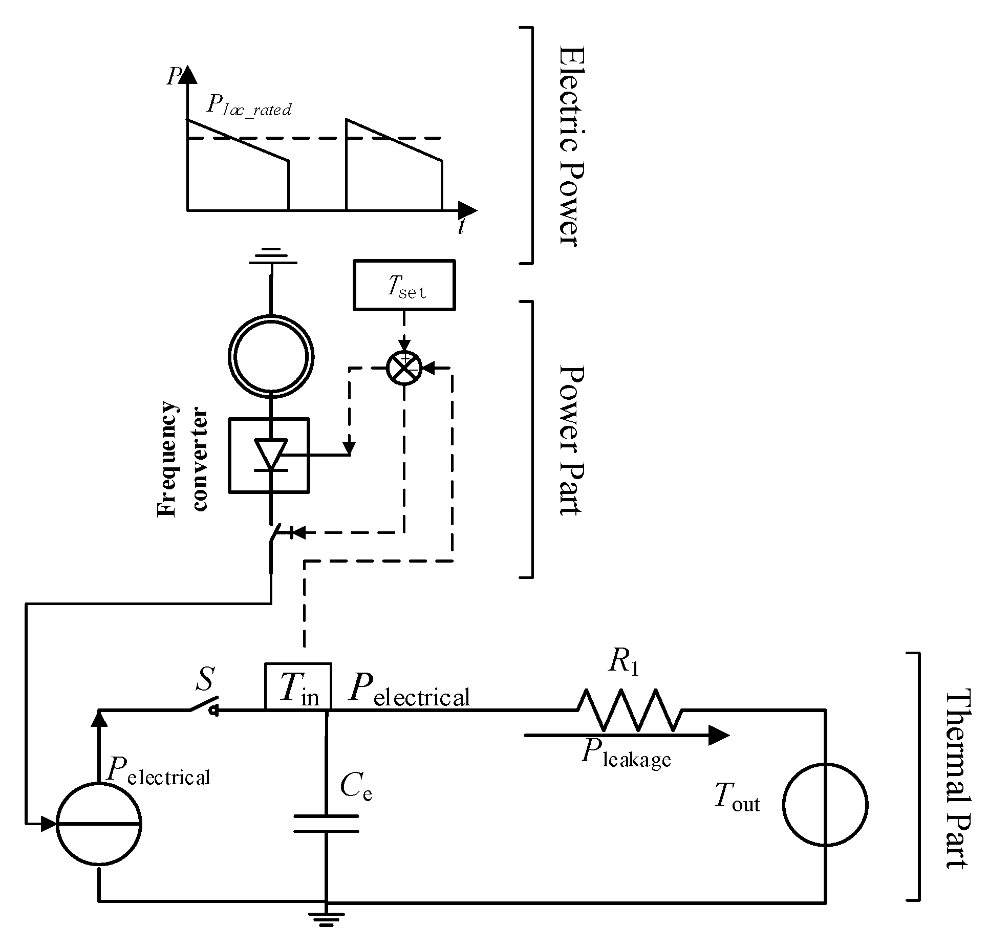
As shown in Figure 2, the VES model of an inverter air conditioner mainly includes the electric power curve, the electrical part, and the thermal part. The power part includes the inverter air conditioner model, and the thermal part is based on the ETP model. The solid arrows indicate the energy flow and the dotted arrows indicate the signal flow.
3. VSOC-Priority Inverter Air Conditioner Control Strategy
The definition of the state-of-charge of the VES is as follows:
where the maximum capacity of the VES is
Capacitance (Ce) is the core parameter related to the energy storage capability of the VES, which can be obtained by using the relationship between temperature and power in the ETP model.
Based on the principle of energy conservation, the charge capacity at time t is
A VSOC-priority VES control strategy is proposed to preferentially select the inverter air conditioners (VESs) with higher VSOC to participate in the demand response; that is, based on the v VSOC value, inverter air conditioners with indoor temperatures in the protocol interval are controlled according to the descending order of VSOC, so that the power can be reduced while the temperature remains unchanged, to meet the power shortages as much as possible under the conditions of ensuring the comfort of users.
3.1. VES Control Model for Inverter Air Conditioners
From the load characteristics of inverter air conditioners, it can be seen that an inverter air conditioner achieves no-difference regulation through adjusting the frequency converter to realize tracking of the load reduction target. There is no great starting power or fluctuation of active power. For the time being, the influence of reactive power on the system is neglected.
In this paper, the heating mode of an inverter air conditioner is taken as an example for analysis; the refrigeration mode, which is very similar, will not be described in this paper. The following assumptions are made: (1) The external environment does not change when the inverter air conditioners participate in demand response; (2) only the energy loss due to the difference between room and external temperatures is considered; (3) the time-step of communication data refresh is Δt; and (4) the minimum heating rate is less than or equal to the heat dissipation rate; that is to say, the temperature of the inverter air conditioner cannot continue to rise when it reaches a set temperature, expressed as:
During normal operation, the inverter air conditioner can achieve smooth regulation, and the indoor temperature should be stable near the set temperature during steady-state. Based on Assumption (4), during demand response, the set temperature of an inverter air conditioner should be taken as the maximum allowable temperature, and there is a pre-agreed minimum temperature.
During demand response, the control right of the inverter air conditioner is transferred from the user to the utility company. In order to consider user comfort, the heating power is reduced to a value that exactly meets the heat exchange between the room and the external environment, so that the room temperature remains unchanged. The electric power of the inverter air conditioner at the time of the control right transfer is obtained from (2) and the energy exchange between the room and the external environment is obtained from (5). Therefore, the discharging power of the VES is the difference between the power at the time of control right transfer and the electric power equivalent to the exchange heat power, while the charging power is the difference between the electric power at the maximum frequency and that of the time of control right transfer. The discharging and charging power of the VES are expressed as
where the subscript Iac represents the inverter air conditioner (which is the core device of a VES); PjIac_disc represents the discharging power of VES j; PjIac_char represents the charging power of VES j; TjIac_in represents the indoor temperature of the room where inverter air conditioner j is located; and TjIac_out represents the outdoor temperature of the room where inverter air conditioner j is located.
By using (2) and (4), (13) and (14) can be converted from the time domain to the temperature domain, thereby transformed as
The virtual state-of-charge of the VES, VSOCjIac, at a certain time t is
Due to the limitations of discharging power, the VSOC of an inverter air conditioner is inversely proportional to the temperature state.
After the end of demand response, if the room temperature in the protocol temperature interval remains unchanged, the VSOC will always be equal to the value at the time when the demand response begins. In the model pre-treatment, the VES of inverter air conditioners can be discretized but cannot be linearized [27]. Therefore, to calculate the VSOC for the VES operation of an inverter air conditioner, we need to first calculate the instantaneous temperature by (6) and, then, by (17).
The charging and discharging time calculated by (7) is
To sum up, taking discharging as an example, the VES control model of the inverter air conditioner is
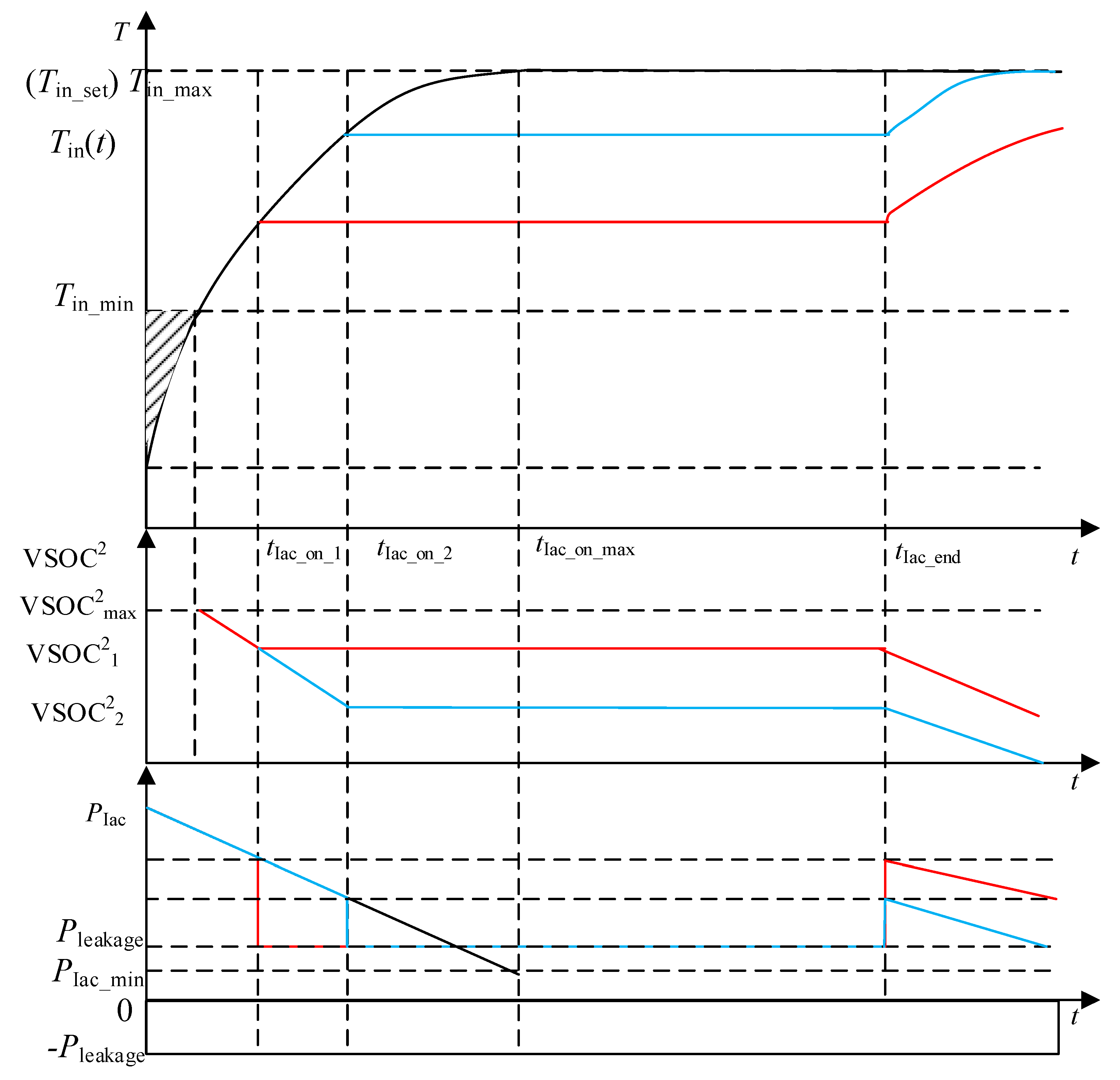
Figure 3 shows the change curves of VES temperature, VSOC, and electric power of an inverter air conditioner. The red and blue lines represent the change curves for which the inverter air conditioners start being controlled, from tIac_on_1 and tIac_on_2, respectively. The inverter air conditioner resumes normal operation at tIac_end, after the control right transfer is over. From Figure 3, it can be seen that the indoor temperature is constant after the inverter air conditioner participates in the demand response at tIac_on_1 (tIac_on_2), which proves the correctness of the temperature maintenance strategy presented in this paper. It can be seen, from (17), that the VSOC largely depends on the current indoor temperature. When the indoor temperature remains unchanged, the value of VSOC also remains constant. As the indoor temperature remains unchanged, the indoor temperature almost reaches the new set value at this time, which makes the operating frequency of the inverter air conditioner reach a minimum value, thus reducing its power consumption and realizing the target of load reduction, in theory.
3.2. Control Strategy and Algorithm Cases
The main objective function of the control strategy is the minimum power shortage over the inverter air conditioner population during demand response in the communication time-step. The constraints are that the value of VSOC of each inverter air conditioner is in the range of 0–1 and that the electric power of each inverter air conditioner is less than or equal to the building heat dissipation power. The specific control function is
where Pts represents the power shortage at time t; Q represents the set of inverter air conditioners, which are sorted in descending order of VSOC; jn is an element of the set Q; and n represents the order of j in the new set.
MATLAB was used as the simulation platform, in order to verify the control effect of trunked dispatching of the air conditioning loads with different parameters and working states. The program mainly included the following steps: (1) Data refresh, (2) dealing with the VSOC off-limit problem, (3) generating the control queue Q based on VSOC values, (4) calculating whether the demand response target was satisfied, and (5) updating the states of the VESs iteratively.
The parameters of the example are as follows: The number of inverter air conditioners was 100; the initial value of VSOC followed a uniform distribution in (0,1); the switching function was sampled evenly from 0–2 (where 0 meant a controlled state, 1 meant the OFF state, and 2 meant a normal operation state); the communication time-step was 1 min; c followed a uniform distribution in (20,25); d followed a uniform distribution in (100,200); the energy efficiency ratio followed a uniform distribution in (2.6,3.4); the minimum temperature of the protocol followed a uniform distribution in (20 °C, 21 °C); the maximum temperature of the protocol followed a uniform distribution in (22 °C, 23 °C); the minimum operating frequency followed a uniform distribution in (20 Hz, 30 Hz); the maximum operating frequency followed a uniform distribution in (140 Hz, 150 Hz); and the indoor initial temperature followed a uniform distribution in (20 °C, 23 °C).
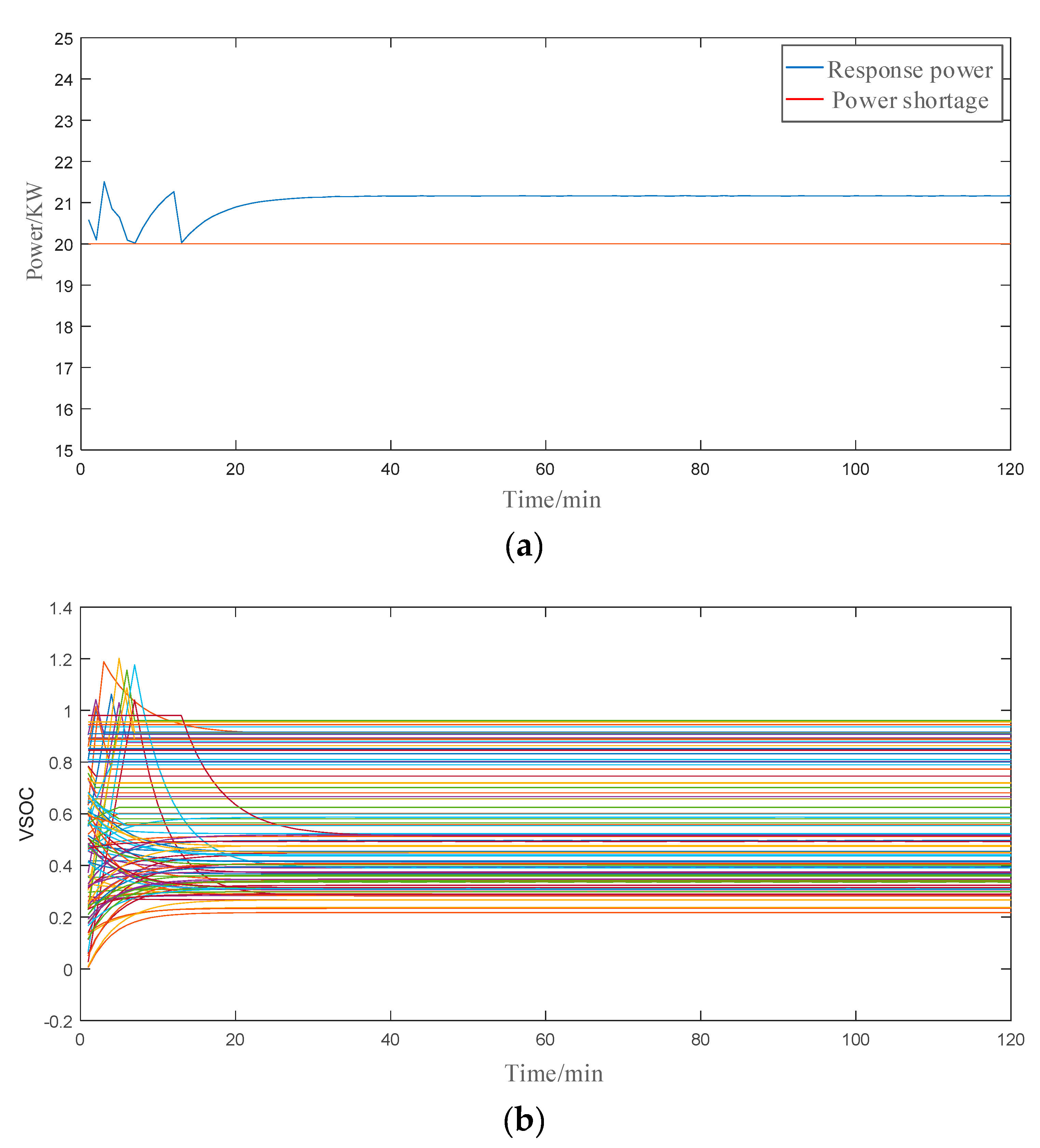
Suppose that the power shortage in the power system is 20 kW (and, thus, the load reduction target of the inverter air conditioner population is 20 kW) and the demand response time period is 120 min. The control results are shown in Figure 4.
From Figure 4, it can be seen that the response power (i.e., the actual amount of load reduction) could fully meet the power shortage (i.e., the load reduction target) during the transfer of control rights. There was a slightly excessive response, but the response power gradually stabilized with time. Therefore, it has been verified that the proposed control strategy can achieve load reduction from inverter air conditioners. It can be seen, from (17), that the VSOC is inversely proportional to the temperature state, so, the larger the VSOC, the smaller the adjustable power. With the passive increase of the charging response power of the VES of the uncontrolled inverter air conditioners, there exists a situation where some controlled VES release their control right in advance.
In summary, the control strategy for an inverter air conditioner can track the power shortage relatively smoothly over a long time and gradually stabilize to a certain state. A constant value of the VSOC means that it is always in the controlled state and the temperature remains unchanged. When the VSOC is greater than or equal to 1, it is turned off. After a period of time, it turns on and operates in a controlled state. A decrease of VSOC indicates that the inverter air conditioner is not under control. The smaller the difference of distance in the set temperature is, the smaller the power consumption is, and the smaller the VSOC value is.
4. Analysis of the Parameters of VSOC-Priority Control for Inverter Air Conditioners
In this section, the influence of load reduction target and communication time-step length on the proposed VSOC-priority control strategy is analyzed.
4.1. Tracking Performance with Different Shape of Load Reduction Targets
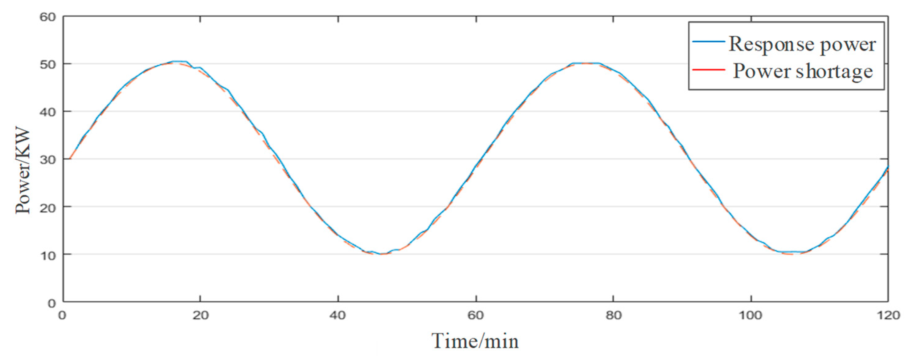
The load reduction target of the power grid was set as a sinusoidal curve with a maximum of 50 kW and a minimum of 10 kW and the control time was set as 120 min.
Figure 5 shows the tracking performance. It can be seen that the VSOC-priority control strategy basically achieved no error in tracking.
4.2. The Influence of the Magnitude of Load Reduction Target on the Control Performance
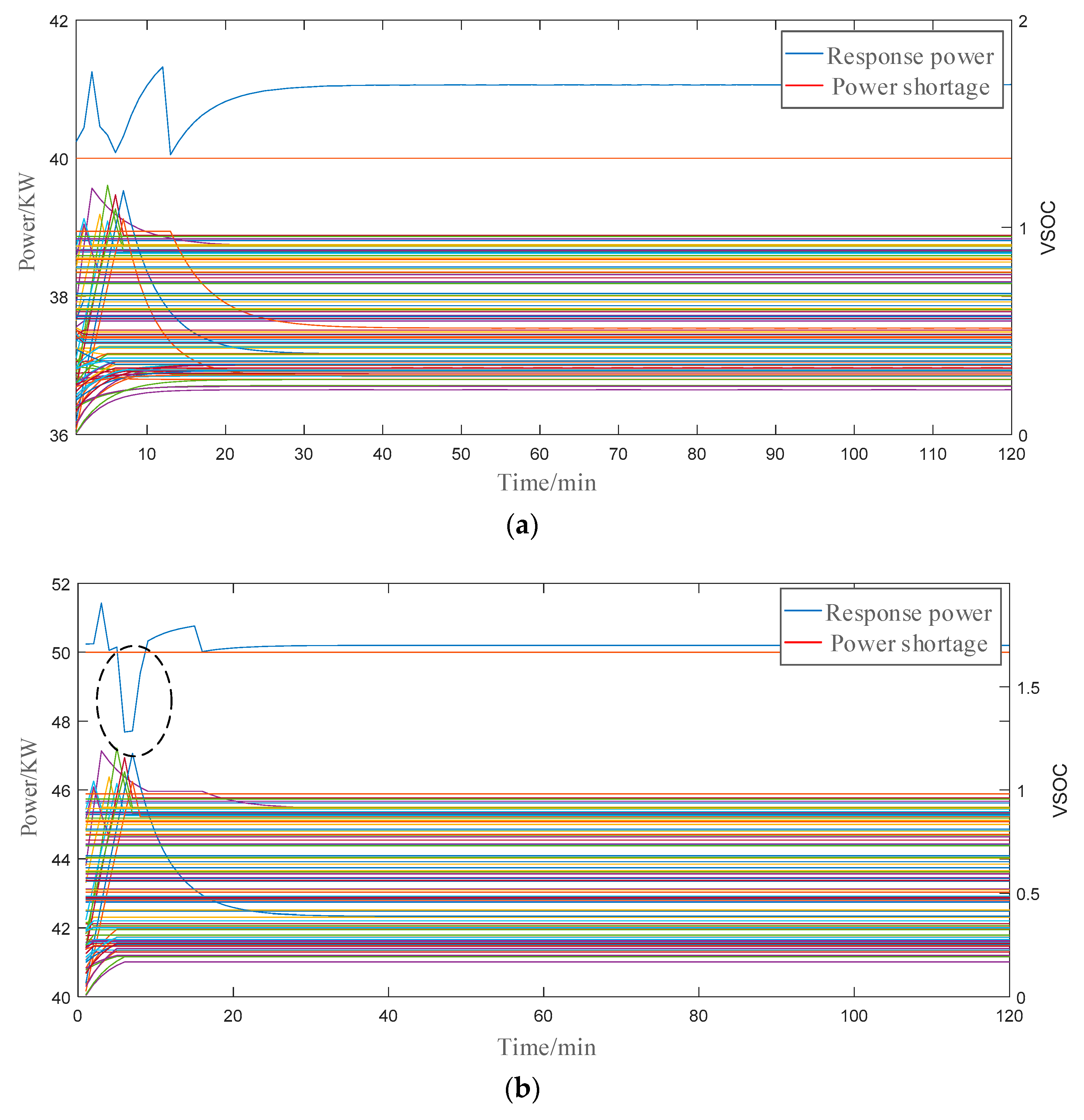
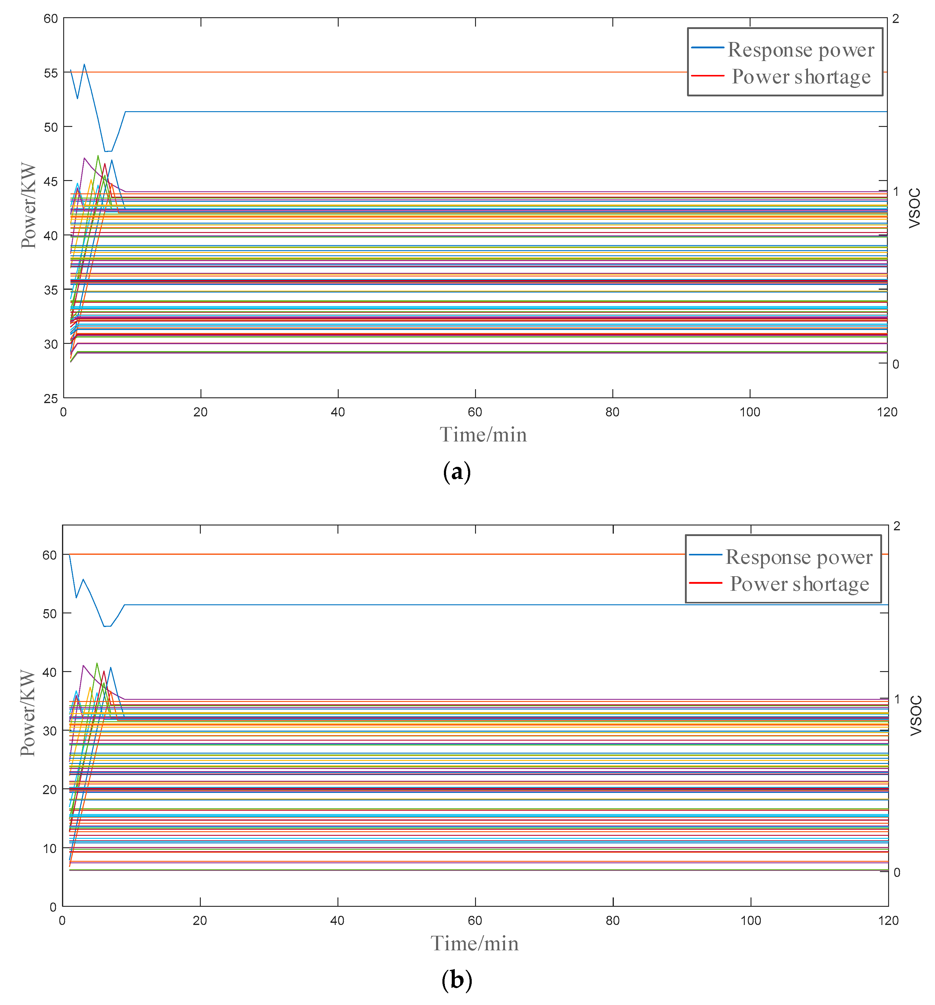
The magnitude of load reduction target was assumed to be 40 kW, 50 kW, 55 kW, and 60 kW to analyze the influence of the magnitude of load reduction target on control performance. The control performance is shown in Figure 6 and Figure 7.
From Figure 6, it can be seen that, when the magnitude of load reduction target is lower than or equal to 50 kW, the proposed control strategy can track the load reduction target relatively smoothly for a long time and gradually stabilize to a certain state. However, due to the large power consumption of inverter air conditioners in the start-up stage, the simultaneous start-up of multiple inverter air conditioners resulted in a reduced amount of load reduction, as shown in the dotted line circle in Figure 6b. As time goes by, the power will gradually stabilize.
From Figure 7, it is seen that when the load reduction target exceeds the capability of the population (e.g., 55 or 60 kW), the actual load reduction at the initial stage of control will produce a large error, stabilize to a level (the maximum capability of the inverter air conditioner population), and remain unchanged. It can be seen that, when the load reduction target is beyond the population capability, there will be larger tracking errors.
4.3. The Influence of Communication Time-step Length on the Control Performance
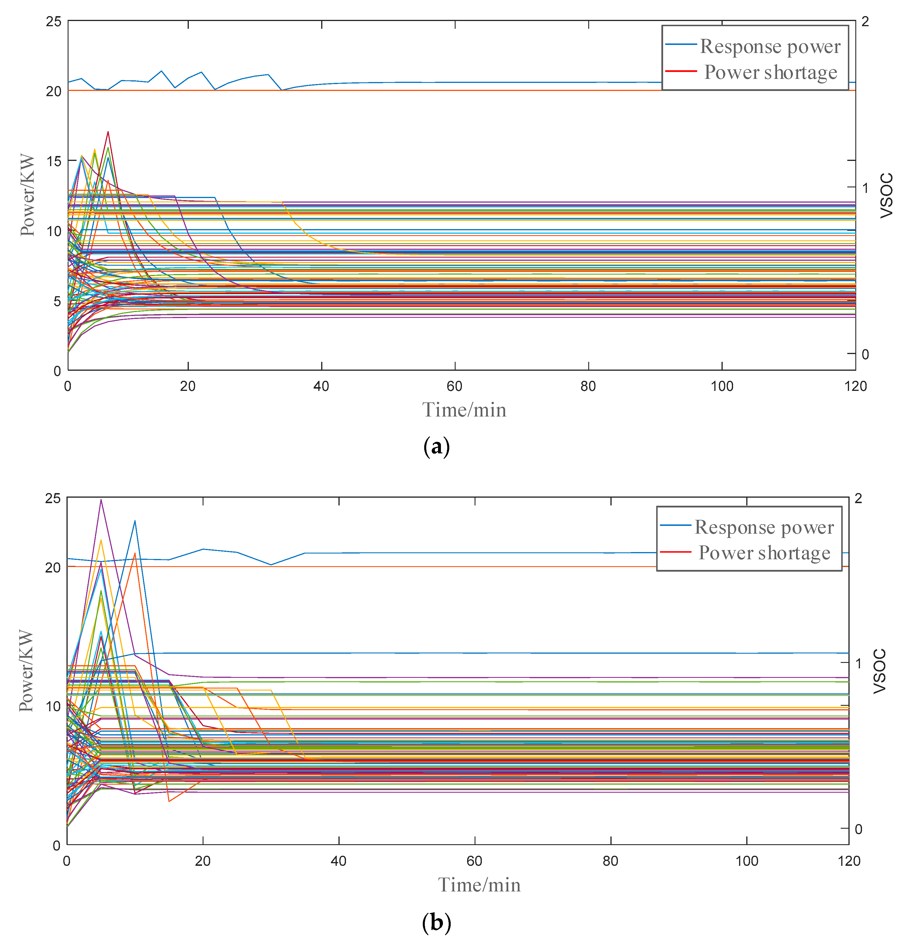
The communication time-step length determines the refresh frequency of the control center for receiving data from the inverter air conditioners and sending control signals. Assume the magnitude of the load reduction target is 20 kW. The communication time-step length was chosen as 2 min and 5 min, respectively, and the total demand response time period was assumed to be 60 min. The control results are shown in Figure 8.
Inverter air conditioners are less affected by communication time-step length, as shown in Figure 8. Except for the increase of VSOC over the limit, the response power can better meet the load reduction target. This is because the theoretical discharging time of the VES in an inverter air conditioner is infinite, and the influence of communication time-step on it is limited.
The simulation results in Figure 8 show that the control performance did not significantly fluctuate and that smooth operation can be basically achieved. However, it is still seen that an increase of communication time-step length reduced the response capability of the VES, resulting in larger power fluctuations and an increased degree of the VSOC over the limit, thus increasing user discomfort. On the other hand, although a shorter communication time-step could result in better control performance, a higher communication frequency will bring greater communication pressure on the advanced metering infrastructure, which will create greater pressure on the data operations of the control center, thus increasing operational costs.
5. Conclusions
This paper investigated the modeling and control of inverter air conditioners in order to provide demand response services for electric power systems. In terms of modeling, based on the ETP model, a complete VES model for inverter air conditioners, which can reflect the practical electro-thermal characteristics, was presented. The model is divided into electrical parameter and thermal parameter parts, reflecting the impact of inverter air conditioning loads on the power grid. The model was further discretized to reduce communications traffic. In terms of control, a virtual state-of-charge priority-based control method was proposed, where the electric power of inverter air conditioners is controlled at a level where the corresponding heating output exactly compensates for the heat loss, such that the indoor temperature will not go beyond a pre-set limit during control.
Simulation results verified the established models and the proposed control method, as well as assessing the impact of various factors. The key findings are as follows:
- (1)
- The control strategy can track the load reduction target smoothly for a long time (120 min, in the simulation) and drive the inverter air conditioners to gradually stabilize to a certain state (within 40 min, in the simulation).
- (2)
- The control strategy can track the load reduction target accurately with different shapes (i.e., constant and sinusoidal targets in our simulation).
- (3)
- The control strategy can track load reduction targets accurately, when they are within the capability of the air conditioner population (below 50 kW, in the simulation), but will have higher errors if the target is beyond the population’s capability (above 50 kW, in the simulation).
- (4)
- A shorter communication time-step (2 min, in the simulation) will result in less power fluctuations and less violation of VSOC limits, compared to a longer time-step (5 min, in the simulation).
Future research topics may include a cost-effectiveness analysis of the proposed control scheme and the remuneration mechanism for compensating customers who participate in the proposed demand response program. For further validation, the proposed control strategy can be tested in real-life systems, if proper conditions are in place.
Author Contributions
Conceptualization, Y.C.; Data curation, J.Y.; Formal analysis, J.Y.; Investigation, S.X.; Methodology, Y.C.; Project administration, Y.C.; Software, J.Y.; Supervision, Y.Z.; Writing—original draft, J.Y.; Writing—review and editing, Y.Z. and S.X.
Funding
This work is supported by Net Zero Energy Consumption Building Project of State Grid Tianjin Binhai Company Zhongxin Tianjin Eco-city (Huifengxi) Smart Energy Town Demonstration Project. (No.19-55; 180310160074).
Conflicts of Interest
The authors declare no conflicts of interest.
References
- Meyn, S.; Barooah, P.; Busic, A.; Chen, Y.; Ehren, J. Ancillary service to the grid using intelligent deferrable loads. IEEE Trans. Autom. Control 2016, 60, 2847–2862. [Google Scholar] [CrossRef]
- Tang, X.J.; Han, J.; Miao, S.H.; Yang, D.; Zhang, Y. Coordinated control model of multi-type load based on demand response. Power Syst. Prot. Control 2017, 45, 116–123. [Google Scholar] [CrossRef]
- Song, M.; Gao, C.W.; Su, W.H. Modeling and controlling of air conditioning load for demand response applications. Autom. Electr. Power Syst. 2016, 40, 158–167. [Google Scholar] [CrossRef]
- Li, Y.; Wang, B.B.; Li, F.X. Outlook and thinking of flexible and interactive utilization of intelligent power. Power Syst. Autom. 2015, 39, 2–9. [Google Scholar] [CrossRef]
- Sun, G.Q.; Li, Y.C.; Wei, Z.N.; Yang, Y.; Zang, H.; Bian, D. Discussion on interactive architecture of smart power utilization. Power Syst. Autom. 2015, 39, 68–74. [Google Scholar] [CrossRef]
- Ruiz, N.; Cobelo, I.; Oyarzabal, J. A direct load control model for virtual power plant management. IEEE Trans. Power Syst. 2009, 24, 959–966. [Google Scholar] [CrossRef]
- Gouveia, C.; Moreira, J.; Moreira, C.L.; Lopes, J.A.P. Coordinating storage and demand response for microgrid emergency operation. IEEE Trans. Smart Grid 2013, 4, 1898–1908. [Google Scholar] [CrossRef]
- Halder, A.; Geng, X.; Kumar, P.R.; Xie, L. Architecture and algorithms for privacy preserving thermal inertial load management by a load serving entity. IEEE Trans. Power Syst. 2016, 32, 3275–3286. [Google Scholar] [CrossRef]
- Sadegh, M.; Xie, L.; Singh, C. Reserves from controllable swimming pool pumps: Reliability assessment and operational planning. In Proceedings of the Hawaii International Conference on System Sciences 2018, Waikoloa Village, HI, USA, 2–6 January 2018; pp. 2547–2556. [Google Scholar] [CrossRef]
- Cammardella, N.; Mathias, J.; Kiener, M.; Bušić, A.; Meyn, S. Balancing California’s grid without batteries. In Proceedings of the 2018 IEEE Conference on Decision and Control (CDC), Miami Beach, FL, USA, 17–19 December 2018; pp. 7314–7321. [Google Scholar] [CrossRef]
- Dou, X.B.; Sun, S.; Lu, B.; Wu, Z.; Liu, J.; Yuan, X. Energy optimization of household microgrid based on adaptive adjustment model of air conditioning. Autom. Electr. Power Syst. 2017, 41, 42–50. [Google Scholar] [CrossRef]
- Hamanaka, M.; Horie, S.; Owaki, D.; Nimi, K.; Yukita, K.; Matsumura, T.; Goto, Y.; Hirose, K. Demand response using air conditioner. In Proceedings of the 2017 IEEE International Telecommunications Energy Conference (INTELEC), Broadbeach, QLD, Australia, 22–26 October 2017. [Google Scholar] [CrossRef]
- Wang, Y.L.; Tong, Y.B.; Huang, M.; Yang, L.; Zhao, H. Research on virtual energy storage model of air conditioning loads based on demand response. Power Syst. Technol. 2017, 41, 394–401. [Google Scholar] [CrossRef]
- Fan, W.; Zhou, N.; Liu, N.; Lin, X.-H.; Zhang, J.-H.; Lei, J.-Y. Time-sharing scheduling model of air conditioning based on demand response and profit allocation. Adv. Technol. Electr. Eng. Energy 2016, 35, 29–35. [Google Scholar] [CrossRef]
- Godina, R.; Rodrigues, E.M.G.; Pouresmaeil, E.; Catalão, J.P.S. Home HVAC energy management and optimization with model predictive control. In Proceedings of the 2017 IEEE International Conference on Environment and Electrical Engineering and 2017 IEEE Industrial and Commercial Power Systems Europe (EEEIC/I&CPS Europe), Milan, Italy, 6–9 June 2017; pp. 1–5. [Google Scholar] [CrossRef]
- Gutierrez-Martinez, V.J.; Moreno-Bautista, C.A.; Lozano-Garcia, J.M.; Pizano-Martinez, A.; Zamora, E.A.; Gómez, M.A. A heuristic home electric energy management system considering renewable energy availability. Energies 2019, 12, 671. [Google Scholar] [CrossRef]
- Qi, Y.B.; Wang, D.; Lan, Y.; Jia, H.J.; Wang, C.; Liu, K.; Hu, Q.; Fan, M. A two-level optimal scheduling strategy for central air conditioners based on metal model with comprehensive state-queueing control models. Energies 2017, 10, 2133. [Google Scholar] [CrossRef]
- Chen, M.; Sun, X.; Huang, L. Extraction of high frequency operating parameters of a compressor motor for a variable frequency air conditioner. J. Tsinghua Univ. 2011, 1326, 423. [Google Scholar]
- Orphelin, M.; Adnot, J. Improvement of methods for reconstructing water heating aggregated load curves and evaluating demand-side control benefits. IEEE Trans. Power Syst. 1999, 14, 1549–1555. [Google Scholar] [CrossRef]
- Yu, N.; He, D.M.; Li, G.Q. Decision factors and classification model of demand response. J. Northeast Dianli Univ. 2011, 31, 112–116. [Google Scholar] [CrossRef]
- Lu, N.; Chassin, D.P. A state-queueing model of thermostatically controlled appliances. IEEE Trans. Power Syst. 2004, 19, 1666–1673. [Google Scholar] [CrossRef]
- Perfumo, C.; Kofman, E.; Braslavsky, J.H.; Ward, J.K. Load management: Model-based control of aggregate power for populations of thermostatically controlled loads. Energy Convers. Manag. 2012, 55, 36–48. [Google Scholar] [CrossRef]
- Ninagawa, C.; Taga, K.; Kiyota, A.; Yamaguchi, T. Emulation system on smart grid Fast Automated Demand Response of widely-distributed stochastically-operating building facilities. In Proceedings of the 2015 IEEE International Symposium on Systems Engineering (ISSE), Rome, Italy, 28–30 September 2015. [Google Scholar] [CrossRef]
- Zhang, Q.Q.; Ou, Y.F.; Guo, Q.; Yang, F. Load Characteristic Comparison Between Inverter and Constant-Speed Air Conditioner and Their Influences on Power Grid. East China Electr. Power 2014, 42, 2017–2021. [Google Scholar]
- Lu, T.T. Research on Energy Storage Modeling and Control Strategy of the Air Conditioning Load. Master’s Thesis, Southeast University, Nanjing, China, 2015. [Google Scholar]
- Cao, X.L.; Yu, S.X.; Li, X.L.; Wang, W.; Liao, S.M. Theoretic and experimental study on domestic air conditioner with R410A as refrigerant. J. Cent. South Univ. (Nat. Sci. Ed.) 2010, 41, 759–763. [Google Scholar]
- Xue, S.Y.; Che, Y.B.; He, W.; Zhao, Y.; Zhang, R. Control strategy of electric heating loads for reducing power shortage in power grid. Processes 2019, 7, 273. [Google Scholar] [CrossRef]
Figure 1.
Relationship between power supply frequency and temperature difference of an inverter air conditioner.
Figure 1.
Relationship between power supply frequency and temperature difference of an inverter air conditioner.

Figure 2.
Virtual energy storage (VES) model of an inverter air conditioner.

Figure 3.
Temperature, virtual state-of-change (VSOC) and power shortage change curves of the VES for an inverter air conditioner with different start control time.
Figure 3.
Temperature, virtual state-of-change (VSOC) and power shortage change curves of the VES for an inverter air conditioner with different start control time.

Figure 4.
Response change of power and VSOC over 120 min. (a) Change curve of response power. (b) Change curve of VSOC of 100 inverter air conditioner VES.
Figure 4.
Response change of power and VSOC over 120 min. (a) Change curve of response power. (b) Change curve of VSOC of 100 inverter air conditioner VES.

Figure 5.
Tracking performance of the proposed VSOC-priority control strategy with a sinusoidal load reduction target.
Figure 5.
Tracking performance of the proposed VSOC-priority control strategy with a sinusoidal load reduction target.

Figure 6.
Control performance of the proposed VSOC-priority control strategy with different magnitudes of load reduction target (within the capability of the air conditioner population). (a) Control effect of VES strategy for 40 kW power shortage inverter air conditioner. (b) Control effect of VES strategy for 50 kW power shortage inverter air conditioner.

Figure 7.
Control performance of the proposed VSOC-priority control strategy with different magnitude of load reduction targets (beyond the capability of the air conditioner population). (a) Control effect of VES strategy for 55 kW power shortage inverter air conditioner. (b) Control effect of VES strategy for 60 kW power shortage inverter air conditioner.

Figure 8.
Control performance of the proposed VSOC-priority control strategy with different communication time-step lengths. (a) Control effect of VES strategy for 2-min time step inverter air conditioner. (b) Control effect of VES strategy for 5-min time step inverter air conditioner.
Figure 8.
Control performance of the proposed VSOC-priority control strategy with different communication time-step lengths. (a) Control effect of VES strategy for 2-min time step inverter air conditioner. (b) Control effect of VES strategy for 5-min time step inverter air conditioner.

© 2019 by the authors. Licensee MDPI, Basel, Switzerland. This article is an open access article distributed under the terms and conditions of the Creative Commons Attribution (CC BY) license (http://creativecommons.org/licenses/by/4.0/).
Share and Cite
MDPI and ACS Style
Che, Y.; Yang, J.; Zhao, Y.; Xue, S. Control Strategy for Inverter Air Conditioners under Demand Response. Processes 2019, 7, 407. https://0-doi-org.brum.beds.ac.uk/10.3390/pr7070407
AMA Style
Che Y, Yang J, Zhao Y, Xue S. Control Strategy for Inverter Air Conditioners under Demand Response. Processes. 2019; 7(7):407. https://0-doi-org.brum.beds.ac.uk/10.3390/pr7070407
Chicago/Turabian StyleChe, Yanbo, Jianxiong Yang, Yuancheng Zhao, and Siyuan Xue. 2019. "Control Strategy for Inverter Air Conditioners under Demand Response" Processes 7, no. 7: 407. https://0-doi-org.brum.beds.ac.uk/10.3390/pr7070407
Note that from the first issue of 2016, this journal uses article numbers instead of page numbers. See further details here.