Environment-Friendly and Efficient Gaseous Insulator as a Potential Alternative to SF6
by
 , ,
, ,
Hafiz Shafqat Kharal
1,* ,
,
Muhammad Kamran
1, 
Rahmat Ullah
2,
Muhammad Zaheer Saleem
2,* and
Muhammad Junaid Alvi
1 1
Department of Electrical Engineering, University of Engineering and Technology, Lahore 54890, Pakistan
2
Faculty of Electrical Engineering, GIK Institute of Engineering Sciences and Technology, Topi 23640, Pakistan
*
Authors to whom correspondence should be addressed.
Processes 2019, 7(10), 740; https://0-doi-org.brum.beds.ac.uk/10.3390/pr7100740
Submission received: 29 August 2019
/
Revised: 19 September 2019
/
Accepted: 8 October 2019
/
Published: 14 October 2019
(This article belongs to the Special Issue Green Sustainable Chemical Processes)
Abstract
:Sulfur hexafluoride (SF6) is commonly used in electrical insulation networks due to its superior dielectric properties. However, it possesses a high Global Warming Potential (GWP) of 22,800 times compared to CO2 (at equal mass over a time span of 100 years) and a high atmospheric lifetime. This alarming metric prompted investigation for substitute gases with minor environmental influences. The overall objective of this research is to evaluate refrigerant R152a as a potential alternative for SF6 in electrical insulation systems. R152a gas has a significantly reduced value of GWP (140) and is a cheap insulation medium as compared to SF6. In this paper, dielectric breakdown testing of R152a and a mixture of CO2 with different concentrations have been tested. The dielectric strength of R152a/CO2 gas shows a saturated growth trend with increasing the gap difference, gas pressure and mixing ratio of R152a. Based on our experimental conditions, R152a/CO2 gas reveals good dielectric properties, and insulation performance can reach up to 96% of SF6. Finally, this work will bring a cost-effective and environment-friendly gaseous insulator for utility companies and power equipment manufacturers.
1. Introduction
Increasing demand for efficient electrical energy use has become a challenge, especially for developing countries with their increased energy usage and poor planning for supply and maintenance. This unplanned and unpredicted exponential rise in energy demand has increased the requirement for deployment of better power protection systems that may withstand undue and unwanted system failures. Therefore, protection equipment should be installed with the best and efficient insulation medium to overcome quick faulty circuit isolation. The most widely used gaseous insulator is sulfur hexafluoride (SF6) with superior arc quenching and insulation abilities [1]. SF6 is a widely used gas and a very prevalent choice in insulation medium for high voltage (HV) apparatus, gas-insulated power lines, compact circuit breaker. It is also non-flammable as compared to the insulating mineral oils particularly for the indoor environments. However, possessing the aforesaid features and properties SF6 has been regrettably found to be a damaging greenhouse gas stated by the Kyoto Protocol that it is 22,800 times more harmful than CO2 for the same masses of both the gases over a time span of 100 years [2,3]. Therefore, SF6 is included in the prohibited list for ecological safety. SF6 decay products, as well as the moisture inside the apparatus, can cause damages to materials like alumina. Therefore, molecular filters were used for harmless exclusion and absorption purposes [4]. Earlier investigations were carried out to expand CF3I/N2 [5,6,7,8,9], C5F10O [10,11], C6F12O [12], C3F7CN [13] and C4F7N [14] as an alternate of SF6, but these candidates have some disadvantages described in Table 1. Gases cannot be maintained in a closed vessel, according to IEC 62271-1 standard there will be a 0.1% leakage from a closed vessel [15]. A worldwide 25-year accumulative data is calculated based on a 0.1% leakage ratio as shown in Table 2 [16,17].
Such critical matters have pointed the emphasis to improve the fidelity and adeptness of power transmission and distribution systems around the world while ensuring that the upcoming modern innovations and latest technologies are not hazardous to the environment.
It is very important to reflect on the environment when designing electric power systems. Such investigation helps to formulate the development of an insulating medium that is environmentally and economically attractive. R152a is a new type of insulating and environmental-friendly gas that has been acknowledged by scholars from all over the world in the past three years. Moreover, a better understanding of the characteristics of R152a and their breakdown mechanisms is developed. The comparative analysis of different SF6 alternatives has been shown in Table 3. Here in Table 3 dielectric strength of all alternatives was normalized to SF6 at 1 bar.
R152a is recognized as a chlorofluorocarbon (CFC), which is commonly used in refrigeration appliances and in aerosol sprays with properties in compliance with the Montreal Protocol [21]. R152a possesses some pertinent qualities making it an effective gas to be employed in the field; for example, it is harmless and non-explosive. All these features make it a suitable candidate for domestic and industrial usage as an electric insulator. R152a gas has a significantly reduced value of GWP (140) and is a cheap insulation medium compared to SF6. Moreover, R152a has zero ozone depletion potential. As the atmospheric lifetime of R152a is 1.4 years so its decomposition products have 98% low environmental impact as compared to SF6. Therefore, using the proposed gas mixture can effectively reduce the greenhouse effect. Table 4 shows a contrast between the physical and chemical properties of R152a and SF6.
Presently, achievements have been made in the dielectric properties of the R152a/CO2 gas mixture. An experimental study on the liquefaction temperature reduction and power frequency breakdown characteristics of R152a/CO2 (different mixtures under different pressure and varying gap distance) was performed. Further, the experimental setup, testing methods, procedures and GWP of R152a/CO2 mixture are elaborated in this paper.
2. Laboratory Test Setup and Assembly of Test Electrodes
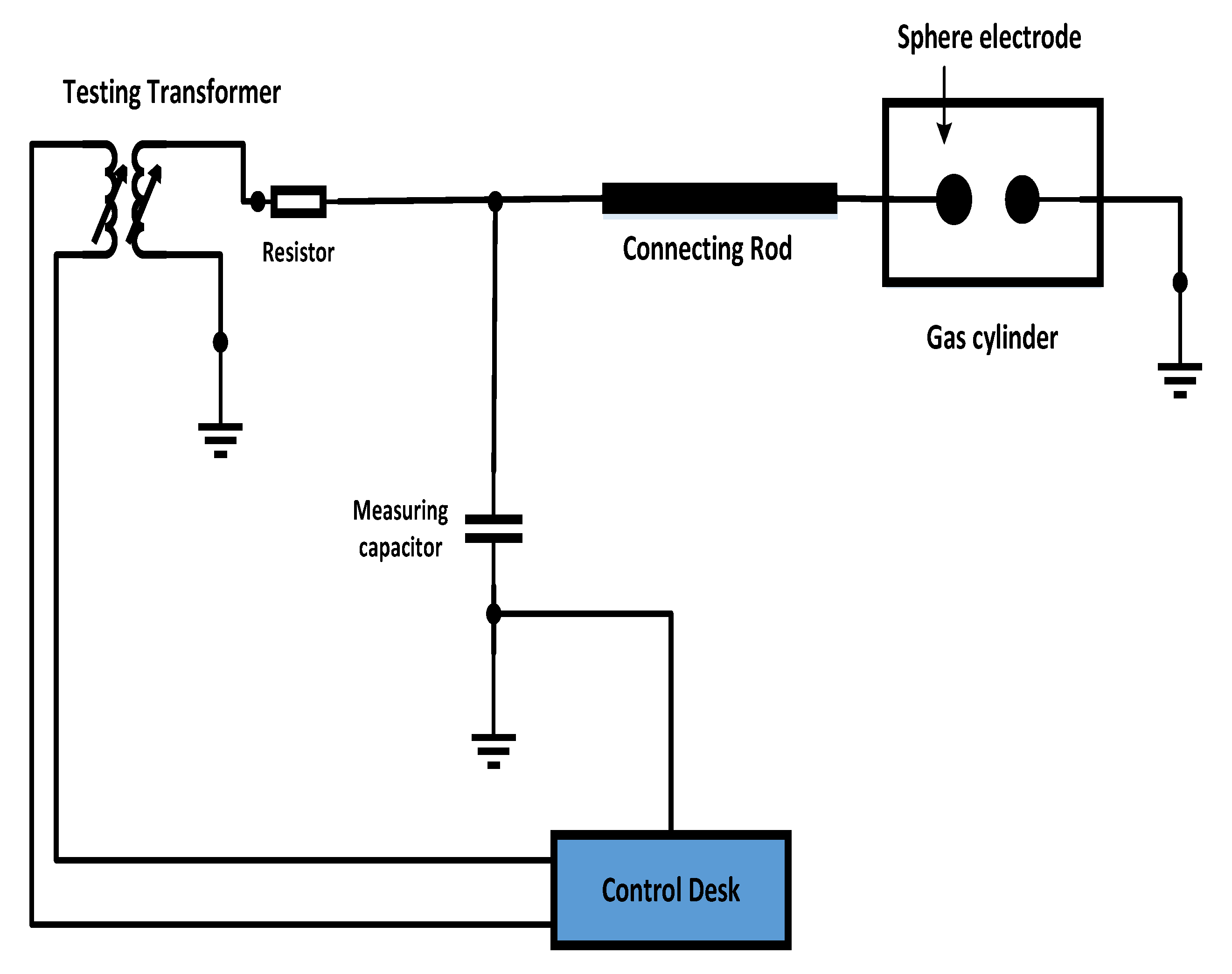
This section describes the experimental test setup in the high voltage laboratory, techniques applied and assembly of test electrodes. Figure 1 shows the schematic for performing the breakdown voltage testing according to the IEC60270 standard [27]. The test setup consists of a control desk (HV-9103) comprising a peak voltmeter (HV 9150) and built-in variable voltage supply. The power supply output is 0 to 230 volts and the voltmeter peak range is 100 to 1000 (kV). The control desk consists of measuring instruments, namely Impulse, Peak, Trigger devices and DC Voltmeters. For DC breakdown testing, through rectification 140 kV DC was generated.
As the breakdown occurs, the voltmeter measures the breakdown voltage across the measuring capacitor. Prior to starting the experimental breakdown voltage tests, AC Voltage of identified value was applied to a voltmeter and measuring devices for calibration purposes to minimize errors and improve precision. All experimental results were obtained at room temperature (20–25 °C). The pressure vessel’s temperature rise has been avoided by the interval of 5 min between two consecutive breakdowns as recommended in [14].
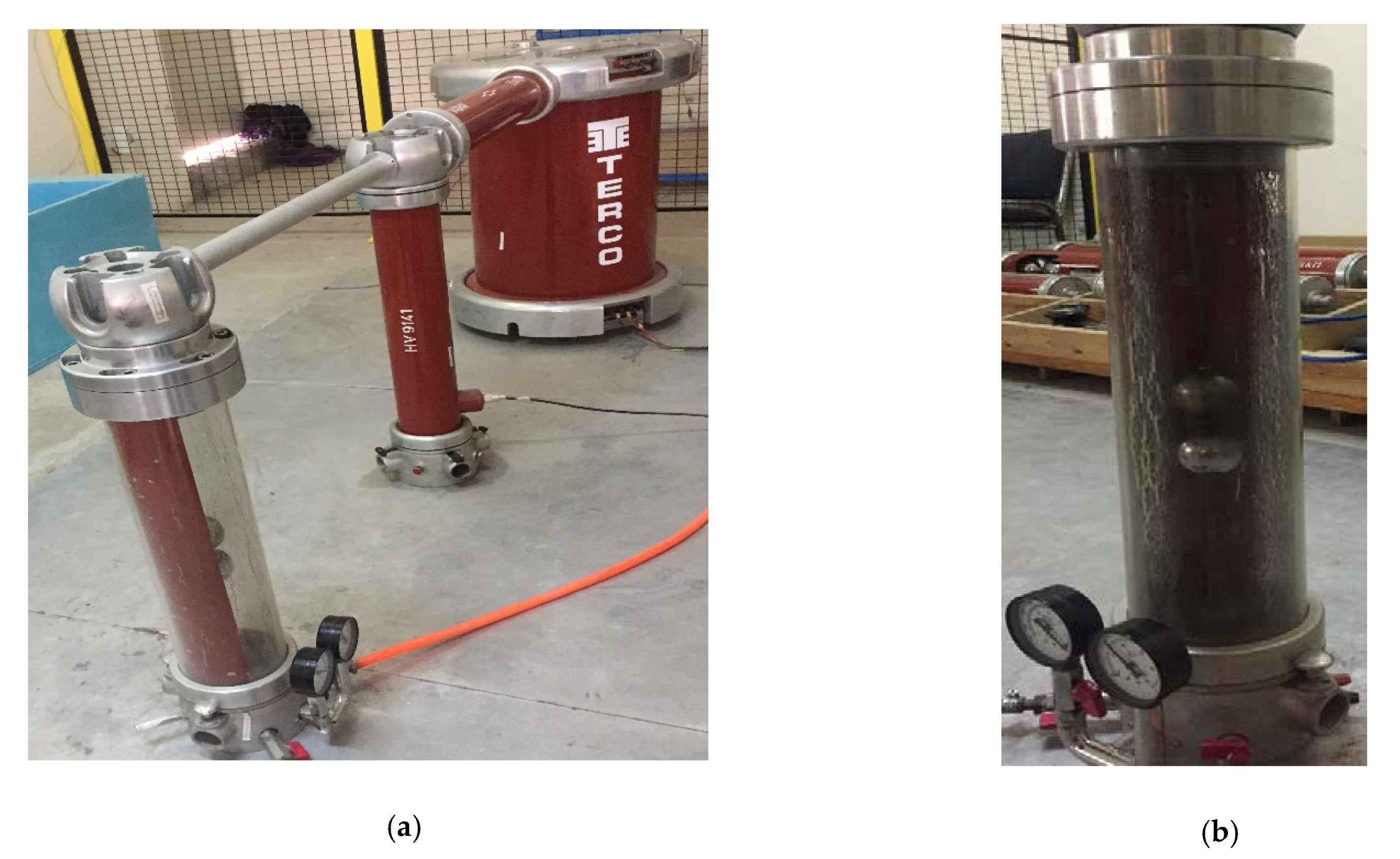
Testing vessel for vacuum and gas is made of steel and equipped with a pressure gauge to measure pressure up to 6 bars. The manufacturing material of the electrode was aluminum enclosed with a nickel coating. The diameter of the electrodes is basically 50 mm. Electrode diameter was selected to be 50 mm because the gap length should be equal or less than the radius of electrode to maintain uniform electric field. In our experimental work the gap length is varied from 0–16 mm, therefore 50 mm is best appropriate diameter of electrodes. Figure 2a,b show experimental setup and testing vessel (HV-9134) respectively. The vessel contains a cylinder made of Plexi-glass that is sandwiched with flanges top and bottom which are linked with high voltage (HV) and ground potential correspondingly. The bottom cover is furnished with essential apparatus, such as inlet, outlet valve measuring gauge for vacuum and pressure. The specifications of the test vessel provided by the manufacturers are briefly described in Table 5.
3. Power Frequency Breakdown Voltage Experiments
3.1. Experimental Procedure
Prior to start testing, both electrodes were cleaned with alcohol dumped silk textile cloth to eliminate moisture and impurities to minimize errors and maximize accuracy in all observations. Tests were carried in dried and moisture-free zone at room temperature. An increase in temperature raises the probability of errors in experimental results. To overcome this problem, time span for each test was restricted to 15–20 min. As R152a and CO2 both are inert and in gaseous form, the time equal to 30–45 min is enough to mix properly for both gases [20].
3.2. Gas Mixture Procedure
3.3. Calculation of Accurate Gas Mixture Pressure
In order to fill up the accurate amount of R152a and CO2 to achieve the accurate ratio of the gas mixture by P/P, the calculation of the amount of gas required is essential. A notable thing here is the P/P ratios of the mixtures of gases because using the W/W ratio would render the calculations incorrect as the molar mass of molecules can change the pressure of the gas mixture heavily. The total amount of R152a and CO2 needed is calculated using the ideal gas law as shown in Equation (1) [25].
where:
m = Mass of gas (grams), T = Temperature (Kelvin), P = Pressure (bar);
MW = Molecular weight of gas (g/mol), R = Ideal gas constant, V = Volume (liters).
For example, in R152a operation, the filling temperature was 20 °C. The ideal gas constant (R) is 0.0821, the MW of R152a is 66.01 g/mol and MW of CO2 = 44.01 g/mol. Therefore, when the chamber is filled with mixture the volume of each gas can be calculated as follows [28]:
In order to fill 80% R152a required amount of this gas
Similarly, for 20% amount of CO2
Therefore, the amount required to fill 80%/20% mixture ratio of R152a/CO2 is 412:117 g.
3.4. Mixture Ratio Analysis
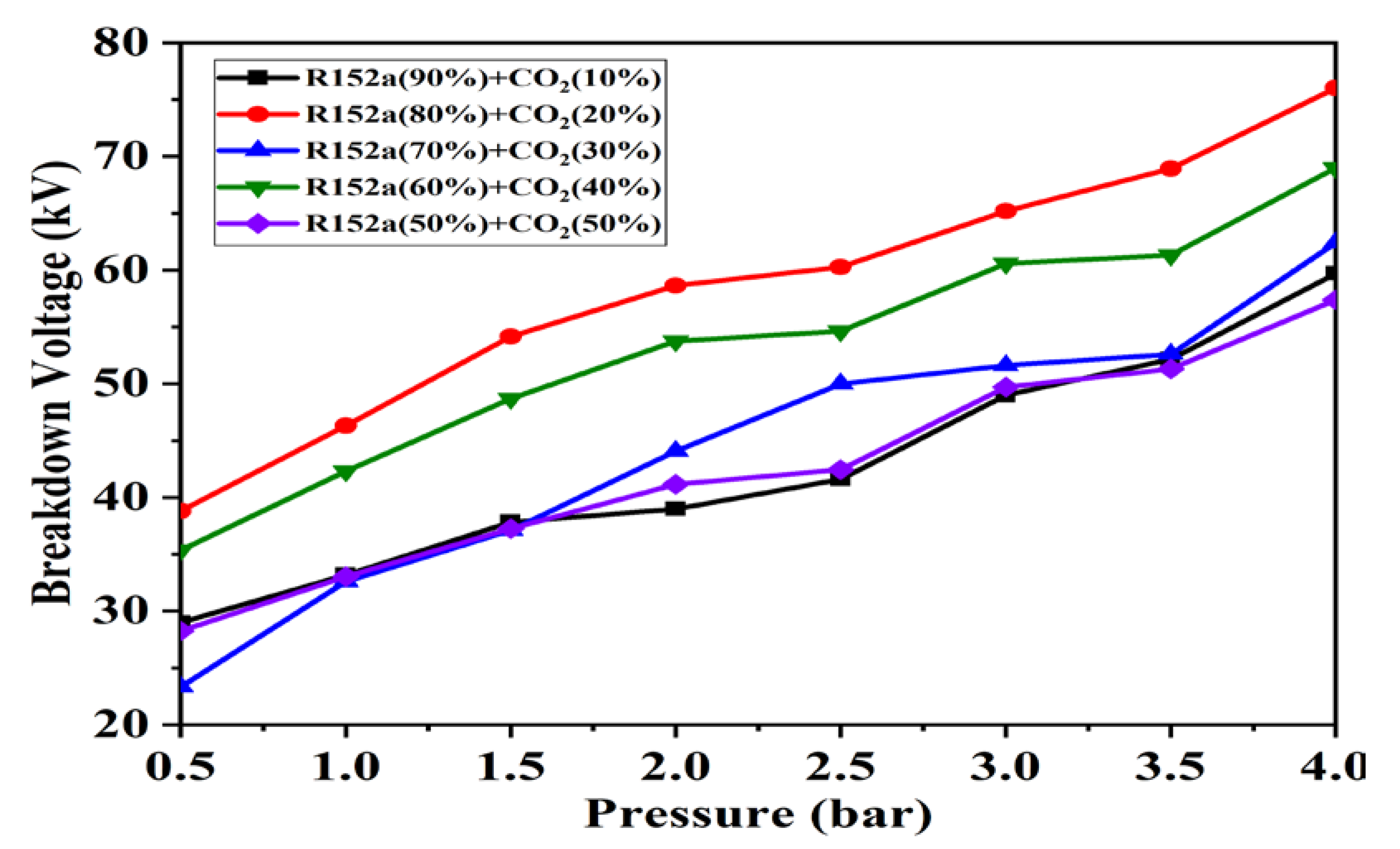
Experiments were performed to locate Alternating Current (AC) power frequency breakdown characteristics on 8 mm electrode distance under these environments (a) pure R152a, (b) pure CO2, (c) CO2 (50%) with addition of R152a (50%), (d) CO2 (40%) with addition of R152a (60%), (e) CO2 (30%) with addition of R152a (70%), (f) CO2 (20%) with addition of R152a (80%) and (g) R152a (10%) with addition of R152a (90%). Figure 3 shows the breakdown strength of R152a and CO2 among their mixture at different R152a/CO2 ratios.
R152a is an electronegative gas, and all negative ions are created by gaining electrons from neutral molecules R152a, which as a result become positive ions after losing electrons. Gaining and losing of the electrons could occur depending on the field applied and attachment and detachment capability of the insulating medium. Losing electrons or detachment coefficients is symbolized by η as shown in Equation (2). When a single electron travels per unit length, several electrons produced in that specified path are defined by Townsend first ionization coefficient, α.
where N refers to initial electron quantity, dN denotes the no of electron traveled a distance dx.
dN = N (α − η) dx
3.5. Dielectric Strength Analysis
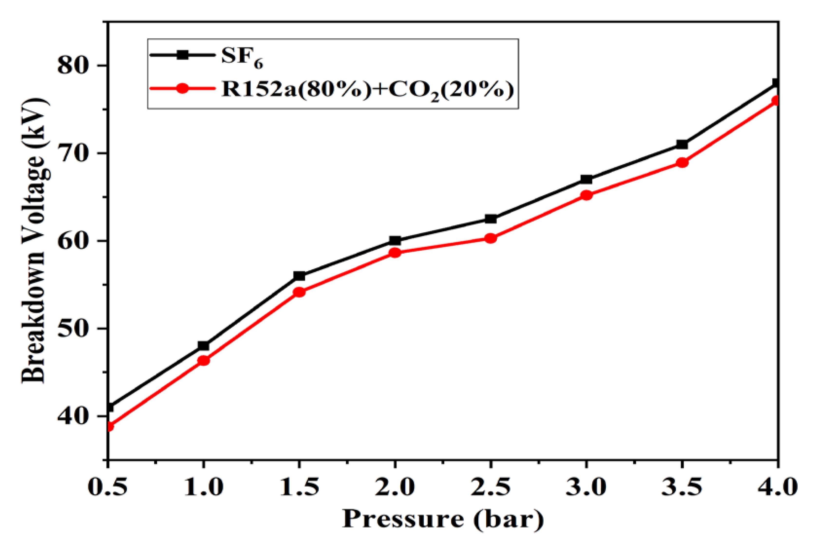
The breakdown strength of R152a and CO2 different mixtures was measured in uniform field under AC voltage. Figure 4 displays the dielectric strength characteristics which can be attained by ratios of 80% and 20% respectively on 4 bar which gives the highest breakdown strength of 96% of SF6 gas.
3.6. Gap Difference Analysis
The breakdown voltage of R152a/CO2 gas varied with the electrode gap distance (4–16 mm). This gap between both electrodes has dominant effects on the gas dielectric strength as shown in Figure 5. In Equation (3) there is an almost linear relationship between the electrode gap and breakdown voltage can be seen [29].
where constant f is demonstrating non-uniformity, V is applied voltage and D is the distance between two electrodes. R152a/CO2 (80%/20%) revealed a similar growth trend as SF6 by changing the gap length as shown in Figure 5. After 12 mm, no significant improvement in breakdown voltage was found for other mixtures of R152a/CO2.
E = f × (V/D)
3.7. Statistical Analysis of R152a
Table 8 demonstrates the statistical analysis of R152a along with CO2. These are premeditatedly designed for variable magnitudes of two mixed gases. The experimental values like standard deviation (SD), coefficient of variation and mean deviation are also depicted in mentioned Table 8 that demonstrates the inconsistency of results achieved through the experiment. The SD of R152a and CO2 (70%/30%) shows a rapid variation in value. Correspondingly, coefficient of variation is observed at the lowest value at (90%/10%) mixing ratio and the mean deviation was found lowest value at (60%/40%) in Table 8.
4. HVDC Analysis
Figure 6 shows the breakdown voltage of R152a/CO2 under HVDC. HVDC in the range of 0–140 kV was generated by the Greincher voltage doubler circuit. The best breakdown strength in case of HVDC was achieved for R152a/CO2 (80%/20%).
5. Global Warming Potential (GWP) Analysis
This novel alternative R152a/CO2 gas mixture has been particularly developed to significantly reduce GWP as compared to SF6. According to environmental protection view, the GWP is calculated as a weighted average of this proposed gas mixture, and from the sum of the weight fractions of each substance and multiplied with their individual GWP as given in Equation (4) where k shows the base gas mixing ratio, 140 is the GWP of R52a and 44 and 56 is the molar mass of R152a and CO2 respectively [14].
The relationship between the GWP value and mixing ratio is shown in Figure 7. It is found that R152a/CO2 mixture contents with ratio 80%/20% at −14.16 °C has a total GWP of 117.17 instead of 22,800 of SF6 over a 100-year time span, effectively reducing the greenhouse effects by 98%.
6. R152a/CO2 Liquefaction Temperature Analysis
In the practical engineering application of new alternate gas, the most important parameter is liquefaction temperature limitation. R152a liquefaction temperature is −25 °C, while that of SF6 is −64 °C. The relationship of vapor pressure with condensation temperature is shown in Figure 8 for R152a and SF6 revealed lower value of condensation temperature for R152a. Thus, it becomes necessary to mix R152a with air, CO2, N2 or buffer gases to meet the requirement of low liquefaction temperature. CO2 has been preferred over other buffer gases like nitrogen and air due to its superior arc quenching ability to produce the appropriate mixture for circuit breaker and disconnect switch applications [30]. In this research, R152a was used along with the mixtures of CO2 resulting in reduced depletion of the ozone layer and acceptable liquefaction temperature.
The formula for calculating the liquefaction temperature or saturated vapor pressure has been given in Equation (5) [31]. The boiling point (b.p) of R152a is greater than SF6 (−63 °C). Due to this reason, buffer gas CO2 is added to reduce the disadvantages of high boiling point because CO2 possess very low b.p. Increasing the CO2 content in the mixture of R152a/CO2 reduces overall b.p. Figure 9 shows mixed gas liquefaction temperature. It was proposed that by increasing the ratio of additive gas, the overall liquefaction temperature was reduced. The characteristic curve was achieved by assuming ideal additive gases.
where P represents the gas boiling point pressure; T is the liquefaction temperature of R152a in mixture with CO2; Tb is the liquefaction temperature (K) at atmospheric pressure; R = 2 cal/deg.mol is the gas constant and A = 21 cal/deg.mol is constant.
7. Conclusions
This paper emphasizes on dielectric properties of R152a/CO2 in different mixture ratios as a potential SF6 substitute for engineering applications and provides guidance for future research. This gas mixture was experimentally investigated and compared with SF6 under power frequency breakdown characteristics, effect of different mixture ratio, pressure and gap distance. GWP is also examined which provides promising results. Considering the liquefaction condition, the following conclusions can be summarized through extensive laboratory testing:
- (1)
- The insulation strength of gas mixture R152a/CO2 (80%/20%) can reach more than 96% of SF6. This enabled us to present the optimal ratio achieved by replacing SF6 as the insulation performance of R152a/CO2 (80%/20%) is close to SF6.
- (2)
- The AC breakdown voltages of R152a/CO2 increase linearly by increasing the gap length. The proposed gas mixture demonstrates good dielectric properties by increasing the content of R152a with comparatively low-temperature applications.
- (3)
- Furthermore, these formulated mixtures are cost-effective and reduce the amount of GWP 98% as compared to pure SF6.
R152a/CO2 is concluded to be a potential proposed composite replacement gas for electrical applications. Therefore, this environment-friendly alternative should be put into practice to save energy and improve the performance of the system.
Author Contributions
Conceptualization, H.S.K. and M.K.; methodology, M.J.A. writing—original draft preparation, H.S.K.; writing—review and editing, M.K., M.Z.S. and R.U.
Funding
This research was funded by Higher Education Commission, Pakistan, grant number 50018514 and the APC was also funded by HEC, Pakistan.
Acknowledgments
The authors thank the higher education commission of Pakistan for financial support to this work’s commencement. A statement of grateful acknowledgment goes to our most respected Rasheed (late) from COMSATS Pakistan for his guidance, project work, and laboratory support.
Conflicts of Interest
The authors declare no conflict of interest.
References
- Kharal, H.S.; Ullah, R.; Ullah, Z.; Asghar, R.; Uddin, W.; Azeem, B.; Ali, S.M.; Haider, A.; Kamran, M. Insulation Characteristic of CCl 2 F 2 with mixtures of CO 2/N as a Possible Alternative to SF 6 substitute Gas for High Voltage Equipment’s. In Proceedings of the 2018 International Conference on Power Generation Systems and Renewable Energy Technologies (PGSRET), Islamabad, Pakistan, 10–12 September 2018; pp. 1–5. [Google Scholar]
- Ullah, R.; Ullah, Z.; Haider, A.; Amin, S.; Khan, F. Dielectric properties of tetrafluoroethane (R134) gas and its mixtures with N2 and air as a sustainable alternative to SF 6 in high voltage applications. Electr. Power Syst. Res. 2018, 163, 532–537. [Google Scholar] [CrossRef]
- Ullah, R.; Rashid, A.; Rashid, A.; Khan, F.; Ali, A. Dielectric characteristic of dichlorodifluoromethane (CCL2F2) gas and mixture with N2/air as an alternative to SF6 gas. High Volt. 2017, 2, 205–210. [Google Scholar] [CrossRef]
- Ray, E.A.; Moore, F.L.; Elkins, J.W.; Rosenlof, K.H.; Laube, J.C.; Röckmann, T.; Marsh, D.R.; Andrews, A.E. Quantification of the SF6 lifetime based on mesospheric loss measured in the stratospheric polar vortex. J. Geophys. Res. Atmos. 2017, 122, 4626–4638. [Google Scholar] [CrossRef]
- Katagiri, H.; Kasuya, H.; Mizoguchi, H.; Yanabu, S. Investigation of the performance of CF3I Gas as a Possible Substitute for SF6. IEEE Trans. Dielectr. Electr. Insul. 2008, 15, 1424–1429. [Google Scholar] [CrossRef]
- Zhang, X.; Xiao, S.; Han, Y.; Cressault, Y. Experimental studies on power frequency breakdown voltage of CF3I/N2 mixed gas under different electric fields. Appl. Phys. Lett. 2016, 108, 092901. [Google Scholar] [CrossRef]
- Xiao, S.; Zhang, X.; Han, Y.; Dai, Q. AC breakdown characteristics of CF 3 I/N 2 in a non-uniform electric field. IEEE Trans. Dielectr. Electr. Insul. 2016, 23, 2649–2656. [Google Scholar] [CrossRef]
- Zhao, S.; Xiao, D.; Zhang, H.; Deng, Y. Discharge characteristics of CF3I/N2 mixtures under lightning impulse and alternating voltage. IEEE Trans. Dielectr. Electr. Insul. 2017, 24, 2731–2737. [Google Scholar] [CrossRef]
- Chen, L.; Widger, P.; Kamarudin, M.S.; Griffiths, H.; Haddad, A. CF3I Gas Mixtures: Breakdown Characteristics and Potential for Electrical Insulation. IEEE Trans. Power Deliv. 2017, 32, 1089–1097. [Google Scholar] [CrossRef]
- Zhang, X.; Li, Y.; Tian, S.; Xiao, S.; Chen, D.; Tang, J.; Zhuo, R. Decomposition mechanism of the C5-PFK/CO2 gas mixture as an alternative gas for SF6. Chem. Eng. J. 2017, 336, 38–46. [Google Scholar] [CrossRef]
- Zhong, L.; Rong, M.; Wang, X.; Wu, J.; Han, G.; Han, G.; Lu, Y.; Wu, Y. Compositions, thermodynamic properties, and transport coefficients of high temperature C5F10O mixed with CO2 and O2 as substitutes for SF6 to reduce global warming potential. AIP Adv. 2017, 7, 075003. [Google Scholar] [CrossRef]
- Zhang, X.; Tian, S.; Xiao, S.; Deng, Z.; Li, Y.; Tang, J. Insulation Strength and Decomposition Characteristics of a C6F12O and N2 Gas Mixture. Energies 2017, 10, 1170. [Google Scholar] [CrossRef]
- Wang, C.; Cheng, Y.; Tu, Y.; Chen, G.; Yuan, Z.; Xiao, A.; Owens, J.; Zhang, A.; Mi, N. Characteristics of C3F7CN/CO2 as an alternative to SF6 in HVDC-GIL systems. IEEE Trans. Dielectr. Electr. Insul. 2018, 25, 1351–1356. [Google Scholar] [CrossRef]
- Zhang, X.; Chen, Q.; Zhang, J.; Li, Y.; Xiao, S.; Zhuo, R.; Tang, J. Experimental Study on Power Frequency Breakdown Characteristics of C4F7N/CO2 Gas Mixture Under Quasi-Homogeneous Electric Field. IEEE Access 2019, 7, 19100–19108. [Google Scholar] [CrossRef]
- International Electrotechnical Commission. High-Voltage Switchgear and Controlgear-Part 1: Common Specifications for Alternating Current Switchgear and Control Gear; IEC 62271-1; International Electrotechnical Commission: London, UK, 2007; p. 252. [Google Scholar]
- Su, Z.; Dengming, X.; Peng, X.; Ruishuang, Z.; Yunkun, D. Analysis of insulation performance and polar effect of CF3I/CO2 mixtures. IEEE Trans. Dielectr. Electr. Insul. 2018, 25, 1364–1370. [Google Scholar] [CrossRef]
- Koch, D. SF6 Properties, and Use in MV and HV Switchgear; Cahier Techique No. 188; Schneider Electric: Rueil-Malmaison, France, 2003. [Google Scholar]
- Okabe, S.; Wada, J.; Ueta, G. Dielectric properties of gas mixtures with C3F8/C2F6 and N2/CO2. IEEE Trans. Dielectr. Electr. Insul. 2015, 22, 2108–2116. [Google Scholar] [CrossRef]
- Zhao, S.; Xiao, D.; Xue, P.; Zhong, R.; Deng, Y. Experimental research on polarity effect of CF3I/N2 mixtures under lightning impulse. IEEE Trans. Dielectr. Electr. Insul. 2018, 25, 1357–1363. [Google Scholar] [CrossRef]
- Zhang, B.; Uzelac, N.; Cao, Y. Fluoronitrile/CO2 mixture as an eco-friendly alternative to SF6 for medium voltage switchgears. IEEE Trans. Dielectr. Electr. Insul. 2018, 25, 1340–1350. [Google Scholar] [CrossRef]
- Nechml, H.E.; Beroual, A.; Girodet, A.; Vinson, P. Effective ionization coefficients and limiting eld strength of fluoronitriles-CO2 mixtures. IEEE Trans. Dielectr. Electr. Insul. 2017, 24, 886–892. [Google Scholar] [CrossRef]
- Xiao, D. Insulating Characteristics of Potential Alternatives to Pure SF6. In Gas Discharge and Gas Insulation; Springer: Heidelberg, Germany, 2016; pp. 271–309. [Google Scholar]
- Li, X.; Zhao, H.; Murphy, A.B. SF6-alternative gases for application in gas-insulated switchgear. J. Phys. D Appl. Phys. 2018, 51, 153001–153009. [Google Scholar] [CrossRef]
- Kovács, T.; Feng, W.; Totterdill, A.; Plane, J.M.C.; Dhomse, S.; Gómez-Martín, J.C.; Stiller, G.P.; Haenel, F.J.; Smith, C.; Forster, P.M.; et al. Determination of the atmospheric lifetime and global warming potential of sulfur hexafluoride using a three-dimensional model. Atmos. Chem. Phys. Discuss. 2017, 17, 883–898. [Google Scholar] [CrossRef] [Green Version]
- Hösl, A.; Pachin, J.; Egüz, E.; Chachereau, A.; Franck, C. Positive synergy of SF6 and HFO1234ze(E). IEEE Trans. Dielectr. Electr. Insul. 2019. [Google Scholar] [CrossRef]
- Hopf, A.; Britton, J.A.; Rossner, M.; Berger, F. Dielectric strength of SF6 substitutes, alternative insulation gases and PFC-gas-mixtures. In Proceedings of the 2017 IEEE Electrical Insulation Conference (EIC), Baltimore, MD, USA, 11–14 June 2017; pp. 209–212. [Google Scholar]
- International Electrotechnical Commission (IEC). High-Voltage Test Techniques—Partial Discharge Measurements; IEC-60270; IEC: London, UK, 2000. [Google Scholar]
- Widger, P.; Griffiths, H.; Haddad, A. Insulation strength of CF3I-CO2 gas mixtures as an alternative to SF6 in MV switch disconnectors. IEEE Trans. Dielectr. Electr. Insul. 2018, 25, 330–338. [Google Scholar] [CrossRef]
- Kasuya, H.; Kawamura, Y.; Mizoguchi, H.; Nakamura, Y.; Yanabu, S.; Nagasaki, N. Interruption capability and decomposed gas density of CF3I as a substitute for SF6 gas. IEEE Trans. Dielectr. Electr. Insul. 2010, 17, 1196–1203. [Google Scholar] [CrossRef]
- Ohtsuka, S.; Nagara, S.; Miura, K.; Nakamura, M.; Hikita, M. Effect of Mixture of a Small Amountof CO2 in SF6/N2 mixed gas on the insulation Performance under Nonuniform Field. In Proceedings of the 2000 IEEE International Symposium on Electrical Insulation, Anaheim, CA, USA, 5 April 2000; pp. 288–291. [Google Scholar]
- Widger, P.; Haddad, A. Evaluation of SF6 Leakage from Gas Insulated Equipment on Electricity Networks in Great Britain. Energies 2018, 11, 2037. [Google Scholar] [CrossRef]
Figure 1.
Schematic to examine R152a/CO2 breakdown voltage by sphere–sphere electrodes.

Figure 2.
Test equipment used: (a) experimental setup; (b) testing vessel (HV-9134).

Figure 3.
AC power frequency breakdown voltage of R152a/CO2 gas at varying mixture ratio and 8 mm electrode gap distance.
Figure 3.
AC power frequency breakdown voltage of R152a/CO2 gas at varying mixture ratio and 8 mm electrode gap distance.

Figure 4.
Breakdown characteristic comparison of R152a/CO2 gas at 80%/20% mixture ratio and SF6 at 8 mm electrode gap distance.
Figure 4.
Breakdown characteristic comparison of R152a/CO2 gas at 80%/20% mixture ratio and SF6 at 8 mm electrode gap distance.

Figure 5.
Breakdown voltages of R152a/CO2 gas varying the gap distance (4–16 mm) at different mixture ratio.
Figure 5.
Breakdown voltages of R152a/CO2 gas varying the gap distance (4–16 mm) at different mixture ratio.

Figure 6.
DC breakdown voltage characteristics of R152a/CO2 with different mixture ratios and 8 mm gap distance.
Figure 6.
DC breakdown voltage characteristics of R152a/CO2 with different mixture ratios and 8 mm gap distance.

Figure 7.
Global Warming GWP analysis of R152a/CO2 gas mixture.

Figure 8.
Saturated vapor pressure R152a and SF6.

Figure 9.
Liquefaction temperature of R152a at different pressure and mixture ratio.


Table 1.
Association of SF6 replacement.
| Gases | Problems and Drawbacks |
|---|---|
| Carbon dioxide, Nitrogen and Dry air | Momentous expansion in pressure. Momentous expansion in size of equipment. Low breakdown voltage [18]. |
| Trifluoro iodomethane mixtures (CF3I/CO2 or N2) | Boiling point large than that of CF3I (−22.5 °C) at 0.1 MPa. Classified as a perilous, mutagenic, and venomous for facsimile (Type-3) [19]. |
| Mixtures of per-fluorinated ketones (C5F10O, C6F12O/Technical air or CO2) | Superior smallest operating temperature than SF6 [20]. Far above the ground boiling temperature (24 °C) at (0.1 MPa) because of higher molecular mass. |
| HFO 1234ze | Carbon grime dump on electrodes owing to high spark voltage. Superior operating temperature than SF6 while unpolluted (constrained at −15 °C). |
| C4F7N/CO2 | Having high boiling point (−4.7 °C at 0.1 MPa) [14] |
Table 2.
Worldwide usage and leakage of SF6 from all GIS.
| Worldwide SF6 Insulated GIS | Expected Mass of Each Component | Total SF6 Used in All GIS | Annually Leakage of SF6 from all GIS | Cumulative 25 Years Leakage of SF6 from All GIS |
|---|---|---|---|---|
| 20,000 | 500 kg | 10,000,000 kg | 9881 Kg | 392,944 Kg |
Table 3.
Different alternative of SF6 gas. The global warming potential represents the values over a time span of 100 years for equal masses of these gases.
Table 3.
Different alternative of SF6 gas. The global warming potential represents the values over a time span of 100 years for equal masses of these gases.
| Reference | Gas | Dielectric Strength (DS) | Global Warming Potential | Atmosphere Lifetime | Boiling Point | Cost/kg |
|---|---|---|---|---|---|---|
| [11] | SF6 | 1 | 22,800 | 3200 | −63 °C | 25–30 $ |
| [22] | N2 | 0.40 | 0 | −195.8 °C | 0.25 times of SF6 | |
| [23] | CO2 | 0.37 | 1 | −78.5 °C | 0.35 times of SF6 | |
| [23] | C2F6 | 0.80 | 12,200 | 10,000 | −78.1 °C | 2.5 times of SF6 |
| [23] | C3F8 | 0.90 | 8830 | 2600 | −36.7 °C | 2 times of SF6 |
| [23] | CF3I | 1.21 | 5 | 0.05 | −22.5 °C | 10 times of SF6 |
| [23] | C4F10 | 1.2–1.3 | 8700 | 3200 | −5.99 °C | 9 times of SF6 |
Table 4.
Contrast between physical and chemical properties of SF6 versus R152a [20]. The global warming potential represents the values over a time span of 100 years for equal masses of these gases. [24,25,26].
| Properties | SF6 | R152a |
|---|---|---|
| GWP | 22,800 | 140 |
| Density | 6.17 kg/m3 | 2.7 kg/cm3 |
| Molecular mass | 146.06 g/mol | 66.1 g/mol |
| Atmospheric life | 3200 | 1.5 |
| Boiling point | −64 °C | −25 °C |
| Appearance | Colorless | Colorless |
| Electronegativity | 2.5 | 2.42 |
| Price/kg | $28 to $30 | $12 |
Table 5.
Test setup specification.
| Specifications | Standards |
|---|---|
| Voltage (AC) | 100 kilovolts |
| Pressure (p) | 0 to 6 bars |
| Diameter of sphere electrodes | 50 mm |
| Vertical height | 800 mm |
Table 6.
Experimental constraints.
| Configuration of Electrodes | Sphere–Sphere |
|---|---|
| Length of spark gap | 6 mm–18 mm |
| AC voltage | 0–100 kV (AC) |
| DC voltage | 0–140 kV (DC) |
| Material of electrode | Aluminum Ni plated steel |
Table 7.
Different mixture ratio of R152a and CO2.
| Measurement No. | R152a Ratio (%) | CO2 Ratio (%) |
|---|---|---|
| 1 | 90 | 10 |
| 2 | 80 | 20 |
| 3 | 70 | 30 |
| 4 | 60 | 40 |
| 5 | 50 | 50 |
Table 8.
Statistical analysis of R152a.
| Base Gas R152a Mixed Gas CO2 | |||||
|---|---|---|---|---|---|
| RBG 1 | 50% | 60% | 70% | 80% | 90% |
| SD | 11.2 | 12.3 | 10.21 | 14.2 | 12.9 |
| Μ | 46.1 | 51.6 | 59.7 | 57.3 | 55.3 |
| cv | 0.23 | 6 | 0.27 | 0.28 | 0.19 |
| Max kV | 60 | 69.8 | 73 | 76.1 | 71.6 |
| Min kV | 26 | 4 | 49.8 | 43 | 35.6 |
1 RBG: Ratio of base gas; SD: standard deviation; M: mean; cv: coefficient of variation.
© 2019 by the authors. Licensee MDPI, Basel, Switzerland. This article is an open access article distributed under the terms and conditions of the Creative Commons Attribution (CC BY) license (http://creativecommons.org/licenses/by/4.0/).
Share and Cite
MDPI and ACS Style
Kharal, H.S.; Kamran, M.; Ullah, R.; Saleem, M.Z.; Alvi, M.J. Environment-Friendly and Efficient Gaseous Insulator as a Potential Alternative to SF6. Processes 2019, 7, 740. https://0-doi-org.brum.beds.ac.uk/10.3390/pr7100740
AMA Style
Kharal HS, Kamran M, Ullah R, Saleem MZ, Alvi MJ. Environment-Friendly and Efficient Gaseous Insulator as a Potential Alternative to SF6. Processes. 2019; 7(10):740. https://0-doi-org.brum.beds.ac.uk/10.3390/pr7100740
Chicago/Turabian StyleKharal, Hafiz Shafqat, Muhammad Kamran, Rahmat Ullah, Muhammad Zaheer Saleem, and Muhammad Junaid Alvi. 2019. "Environment-Friendly and Efficient Gaseous Insulator as a Potential Alternative to SF6" Processes 7, no. 10: 740. https://0-doi-org.brum.beds.ac.uk/10.3390/pr7100740
Note that from the first issue of 2016, this journal uses article numbers instead of page numbers. See further details here.