Hydrophobic and Anti-Icing Behavior of UV-Laser-Treated Polyester Resin-Based Gelcoats

 ,
,  ,
,  ,
,  and
and
Abstract
:1. Introduction
2. Materials and Methods
3. Results
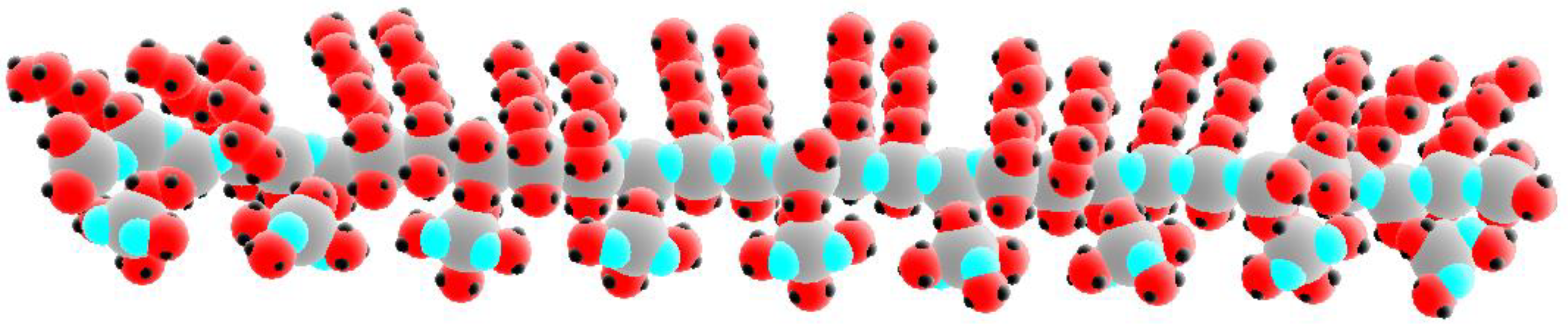
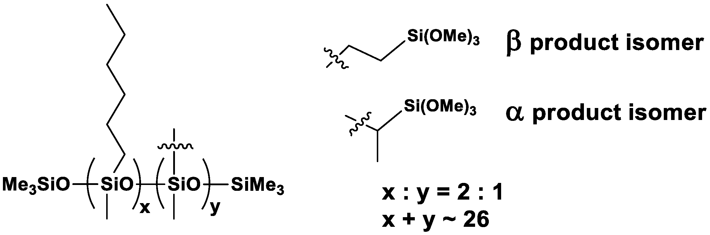
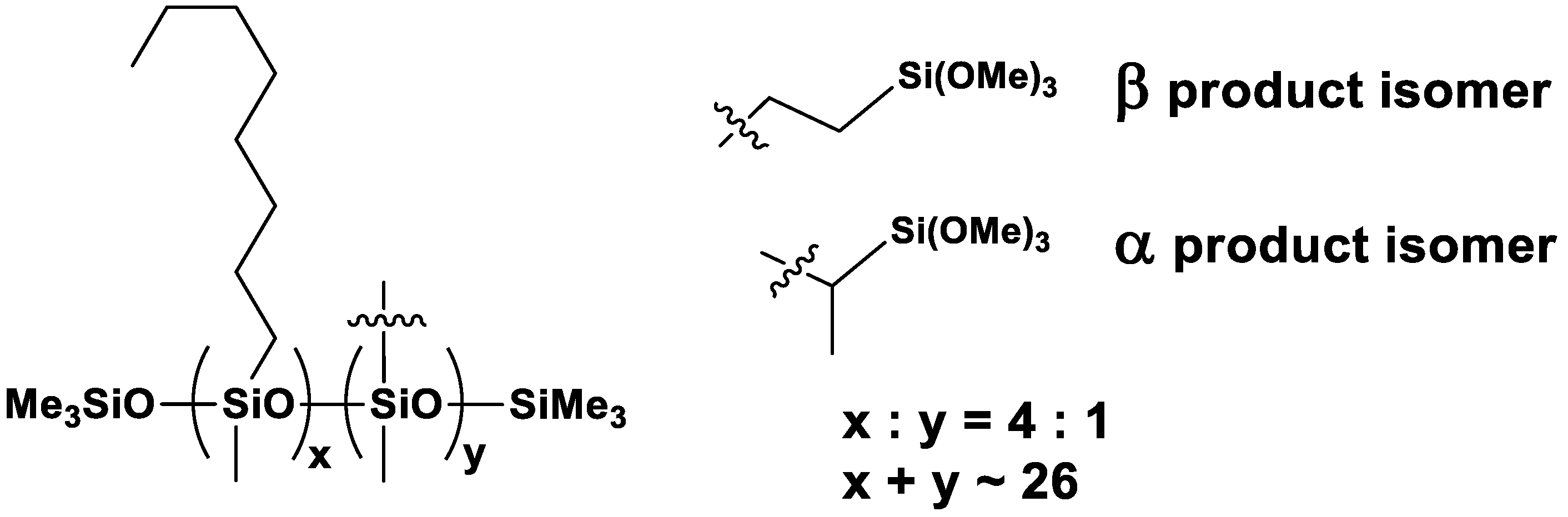
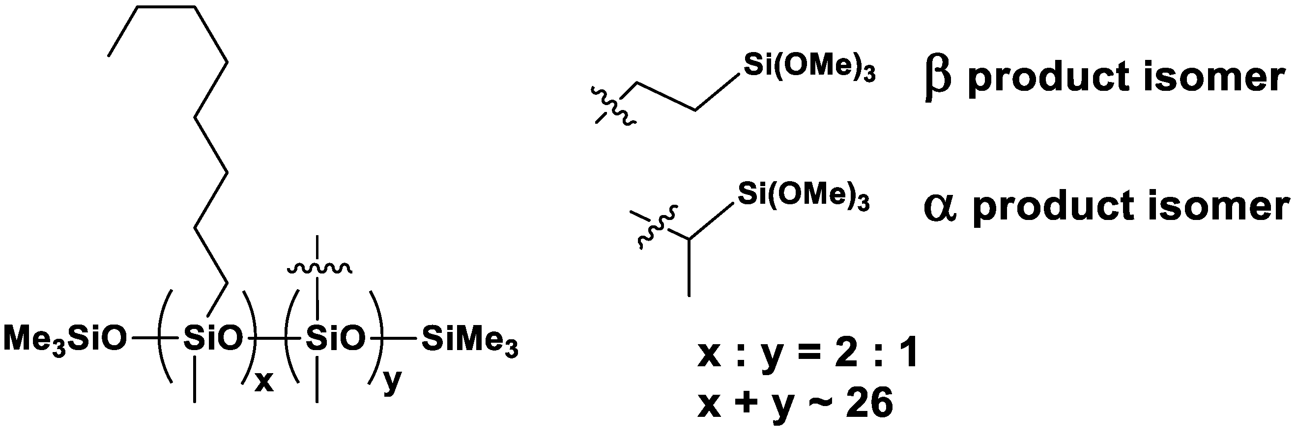
3.1. Characterization of Organosilicon Modifiers
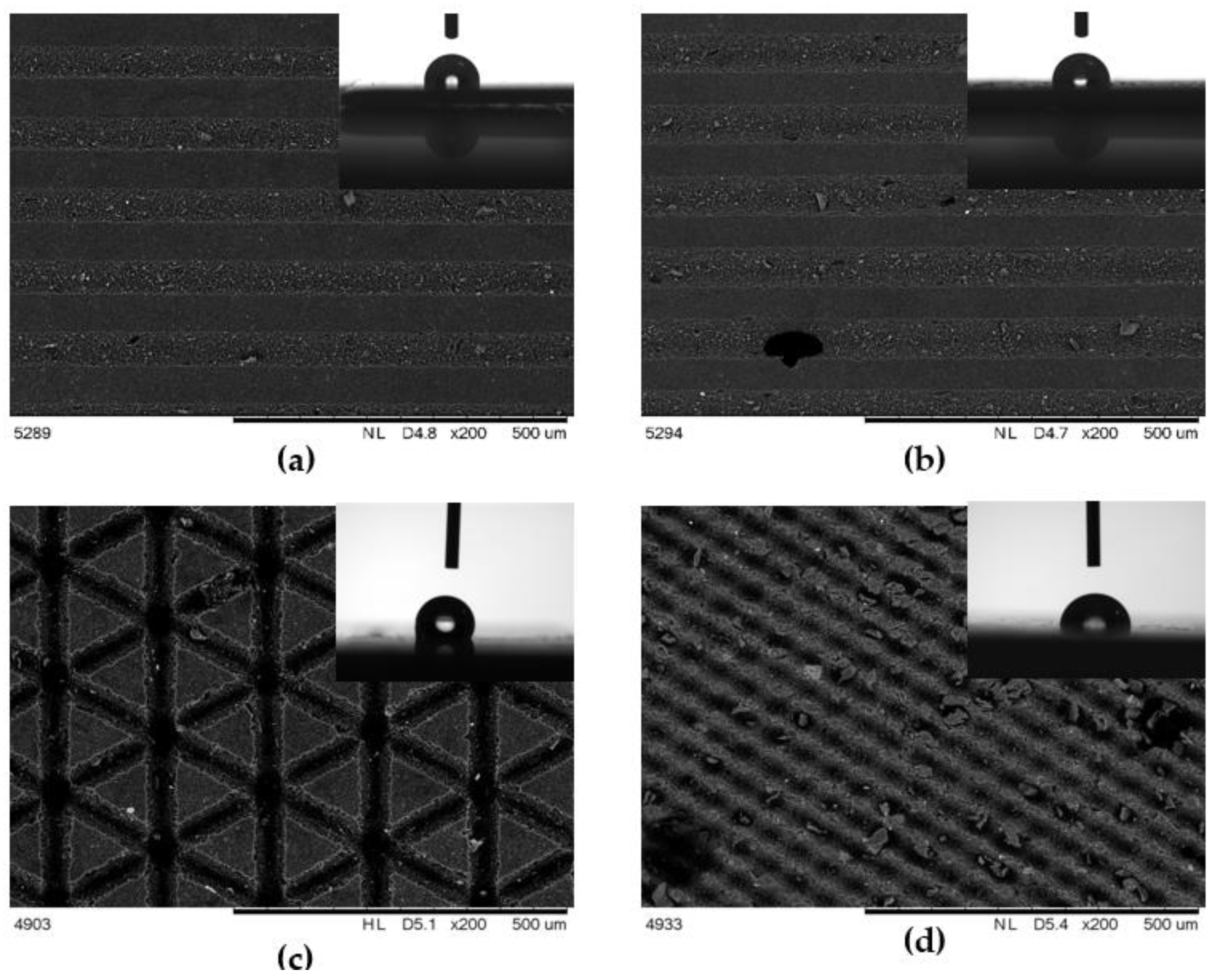
3.2. Scanning Electron Miscroscopy
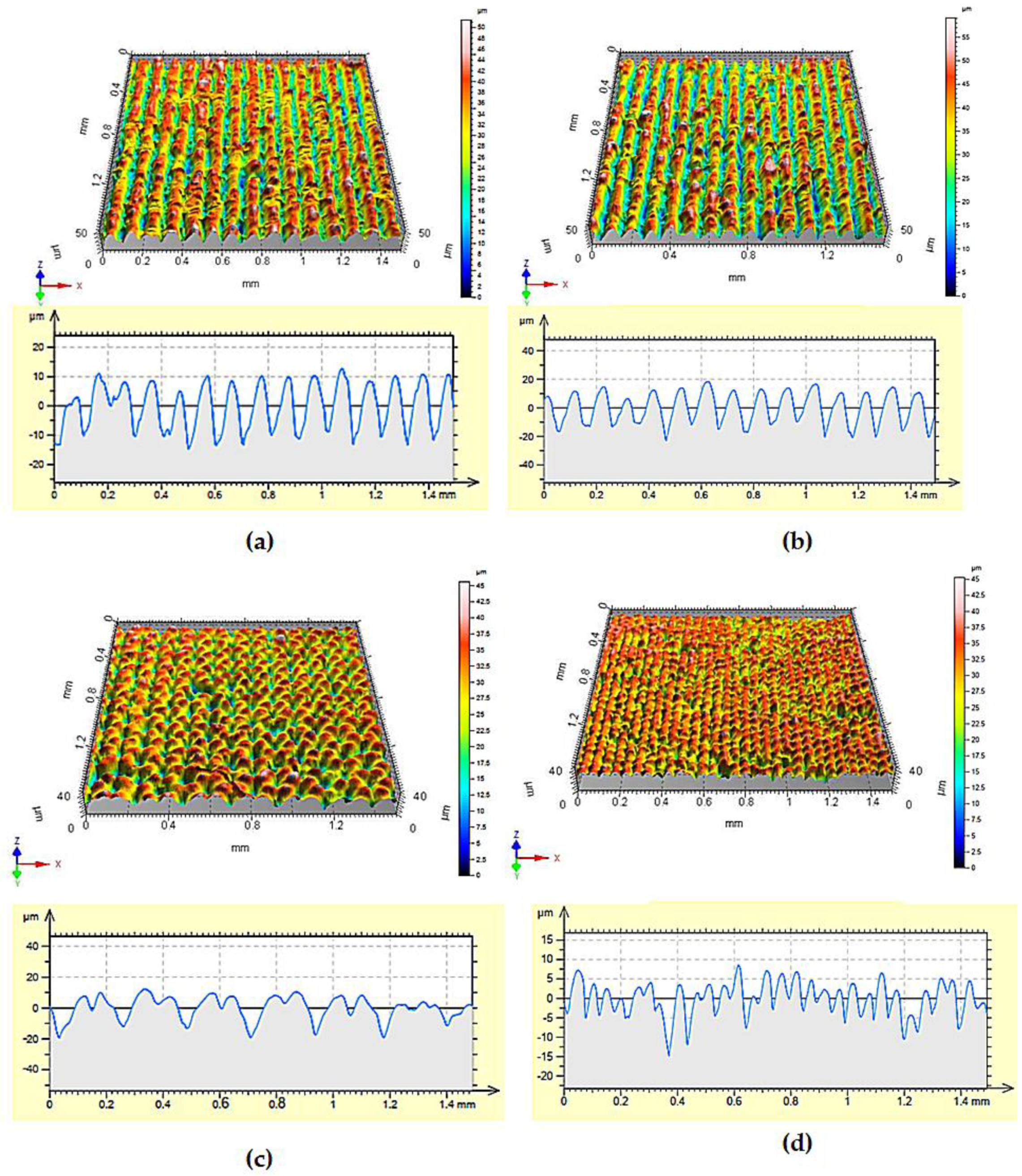
3.3. Surface’s Profile
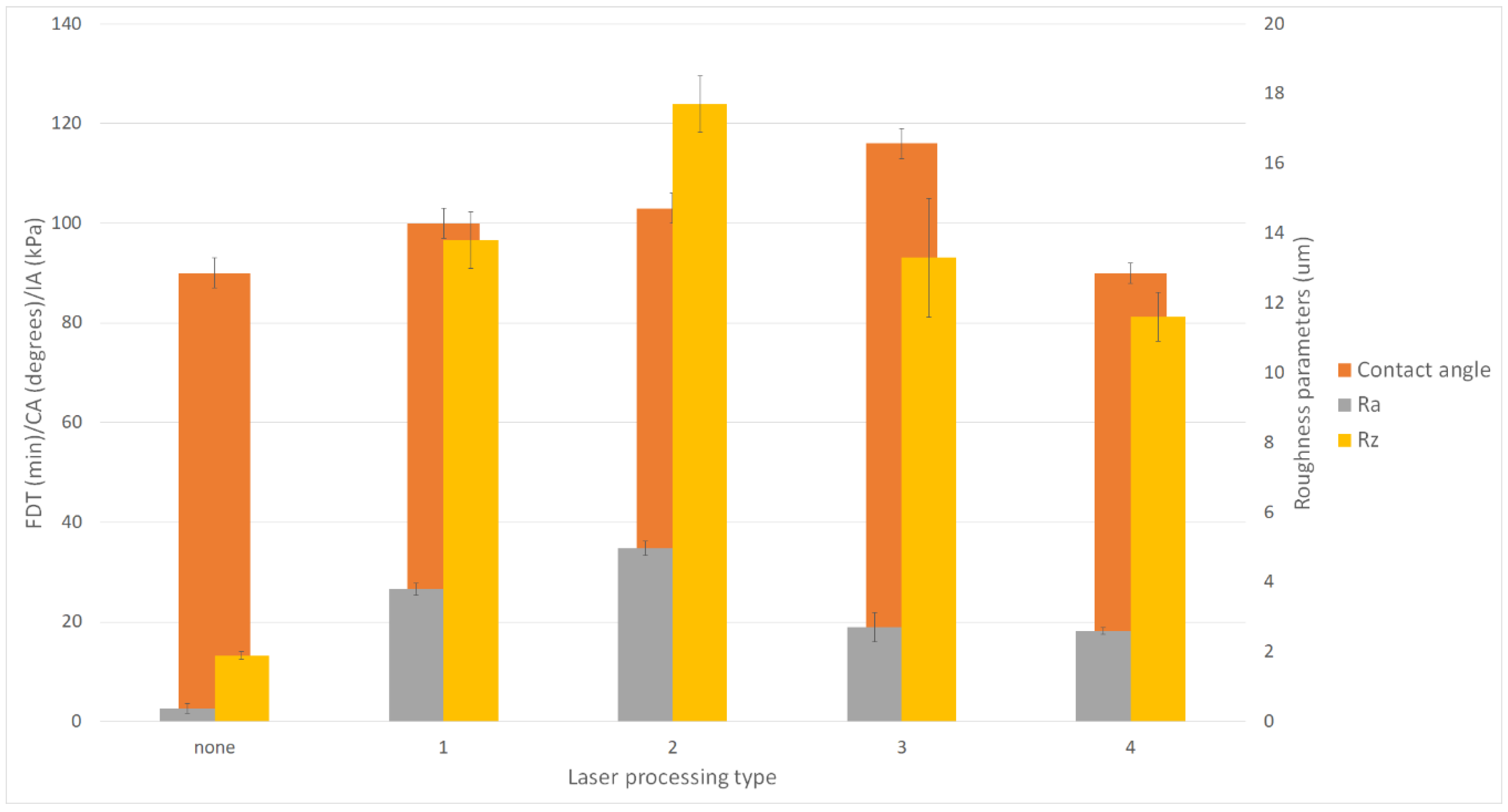
3.4. Wettability
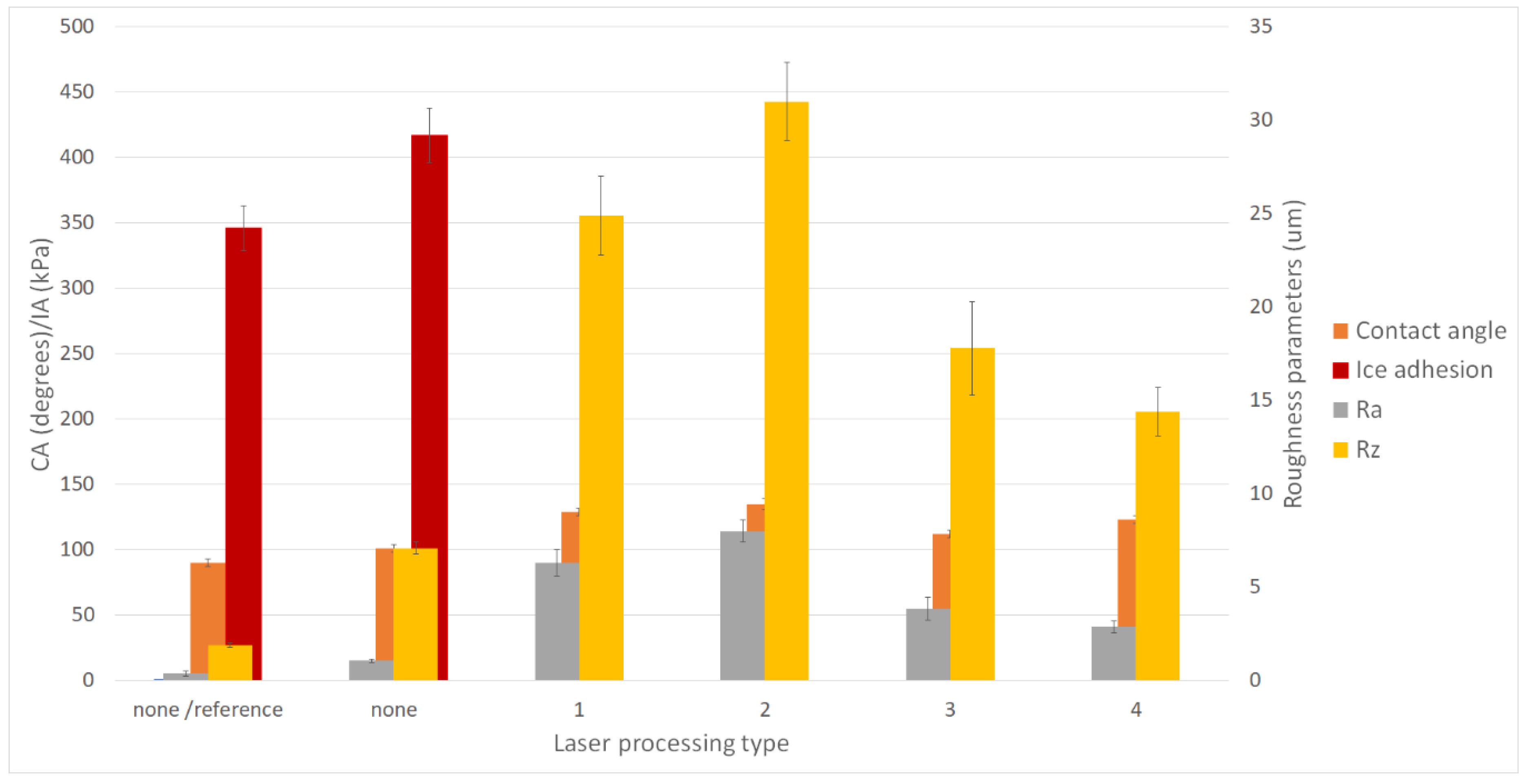
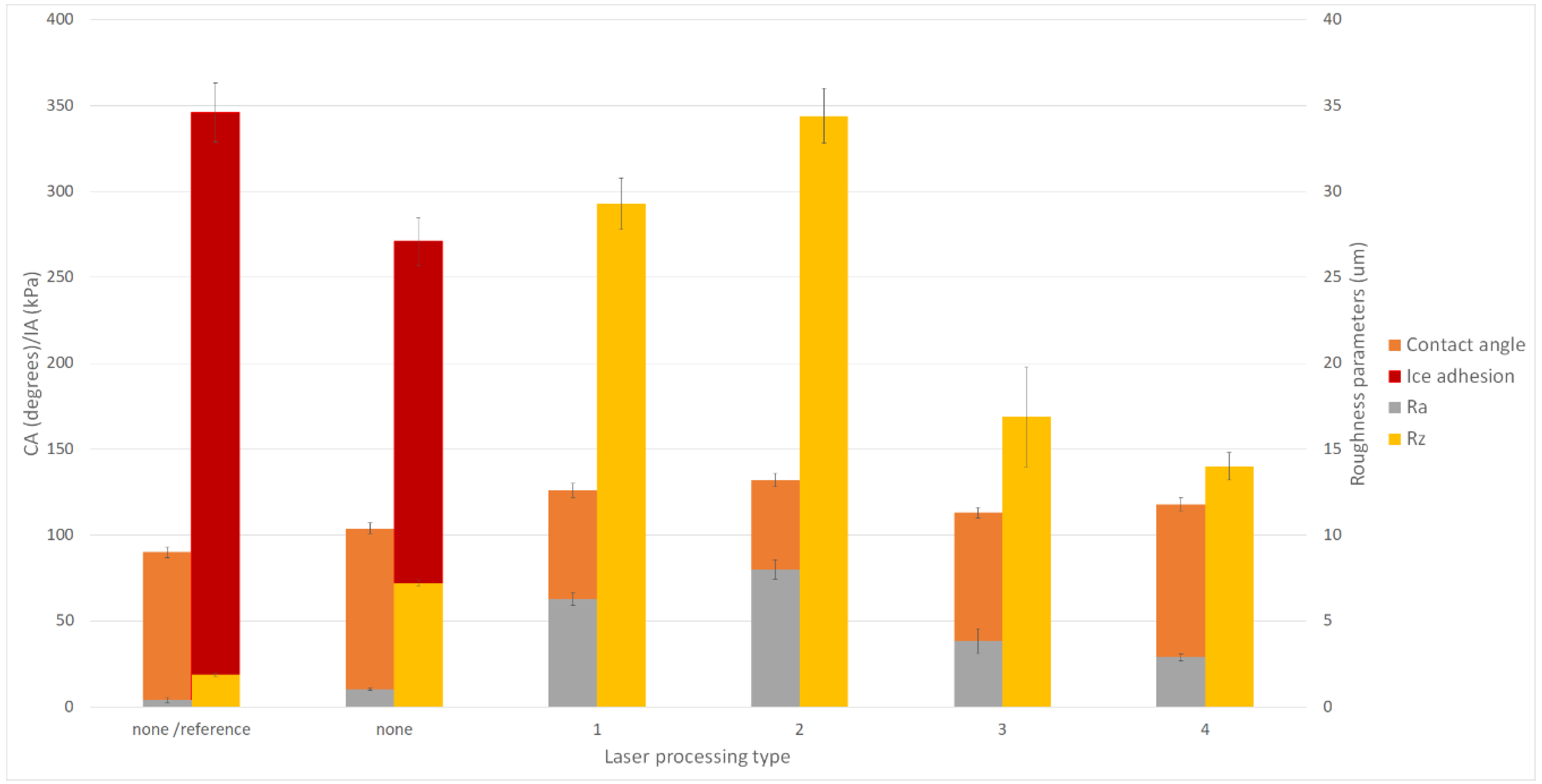
3.5. Ice Adhesion
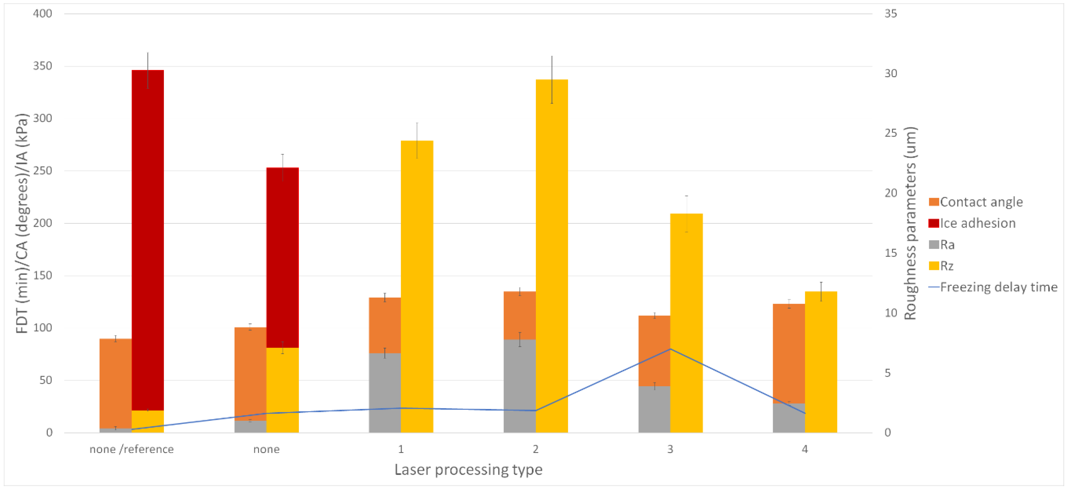
3.6. Freezing Time Delay
4. Discussion
5. Conclusions
Author Contributions
Funding
Acknowledgments
Conflicts of Interest
References
- Komusanac, I.; Brindley, G.; Fraile, D. Wind energy in Europe in 2019. Trends and Statistics. Available online: https://windeurope.org/about-wind/statistics/european/wind-energy-in-europe-in-2019/f (accessed on 16 September 2020).
- Wind Explained. Electricity Generation from Wind. Available online: https://www.eia.gov/energyexplained/wind/electricity-generation-from-wind.php#:~:text=U.S. total annual Electricity generation,U.S. utility-scale electricity generation (accessed on 16 September 2020).
- Simani, S. Overview of Modelling and Advanced Control Strategies for Wind Turbine Systems. Energies 2015, 8, 13395–13418. [Google Scholar] [CrossRef] [Green Version]
- Tavner, P.J.; Greenwood, D.M.; Whittle, M.W.G.; Gindele, R.; Faulstich, S.; Hahn, B. Study of weather and location effects on wind turbine failure rates. Wind Energy 2013, 175–187. [Google Scholar] [CrossRef]
- Ibrahim, M.E.; Medraj, M. Water droplet erosion ofwind turbine blades: Mechanics, testing, modeling and future perspectives. Materials 2020, 13, 157. [Google Scholar] [CrossRef] [Green Version]
- Zhang, S.; Dam-Johansen, K.; Bernad, P.L.; Kiil, S. Rain erosion of wind turbine blade coatings using discrete water jets: Effects of water cushioning, substrate geometry, impact distance, and coating properties. Wear 2015, 328–329, 140–148. [Google Scholar] [CrossRef]
- Das, S.; Kumar, S.; Samal, S.K.; Mohanty, S.; Nayak, S.K. A Review on Superhydrophobic Polymer Nanocoatings: Recent Development and Applications. Ind. Eng. Chem. Res. 2018, 57, 2727–2745. [Google Scholar] [CrossRef]
- Jiang, Z.; Wang, X.; Jia, H.; Zhou, Y.; Ma, J.; Liu, X.; Jiang, L.; Chen, S. Superhydrophobic polytetrafluoroethylene/heat-shrinkable polyvinyl chloride composite film with super anti-icing property. Polymers 2019, 11, 805. [Google Scholar] [CrossRef] [PubMed] [Green Version]
- Yilgor, I.; Bilgin, S.; Isik, M.; Yilgor, E. Facile preparation of superhydrophobic polymer surfaces. Polymer 2012, 53, 1180–1188. [Google Scholar] [CrossRef]
- Cohen, N.; Dotan, A.; Dodiuk, H.; Kenig, S. Superhydrophobic Coatings and Their Durability. Mater. Manuf. Process. 2016, 31, 1143–1155. [Google Scholar] [CrossRef]
- Battisti, L. Optimising wind turbine design for operation in cold climates. Wind Energy Syst. Optimising Des. Constr. Safe Reliab. Oper. 2010, 388–460. [Google Scholar] [CrossRef]
- Dalili, N.; Edrisy, A.; Carriveau, R. A review of surface engineering issues critical to wind turbine performance. Renew. Sustain. Energy Rev. 2009, 13, 428–438. [Google Scholar] [CrossRef]
- Tiwari, A. A Study of Icephobic Coatings. Part I. PCI Magazine. 2020, pp. 38–42. Available online: https://www.pcimag.com/articles/106963-a-study-of-icephobic-coatings-part-1 (accessed on 15 January 2020).
- Karthikeyan, N.; Anand, R.B.; Suthakar, T.; Barhate, S. Materials, Innovations and Future Research Opportunities on Wind Turbine Blades—Insight Review. Environ. Prog. Sustain. Energy 2019, 38. [Google Scholar] [CrossRef]
- Liu, J.; Wang, J.; Mazzola, L.; Memon, H.; Barman, T.; Turnbull, B.; Mingione, G.; Choi, K.S.; Hou, X. Development and evaluation of poly(dimethylsiloxane) based composite coatings for icephobic applications. Surf. Coat. Technol. 2018, 349, 980–985. [Google Scholar] [CrossRef] [Green Version]
- Nishimura, R.; Hyodo, K.; Sawaguchi, H.; Yamamoto, Y.; Nonomura, Y.; Mayama, H.; Yokojima, S.; Nakamura, S.; Uchida, K. Fractal Surfaces of Molecular Crystals Mimicking Lotus Leaf with Phototunable Double Roughness Structures. J. Am. Chem. Soc. 2016, 138, 10299–10303. [Google Scholar] [CrossRef] [PubMed]
- Jamil, M.I.; Ali, A.; Haq, F.; Zhang, Q.; Zhan, X.; Chen, F. Icephobic Strategies and Materials with Superwettability: Design Principles and Mechanism. Langmuir 2018, 34, 15425–15444. [Google Scholar] [CrossRef] [PubMed]
- Schutzius, T.M.; Jung, S.; Maitra, T.; Eberle, P.; Antonini, C.; Stamatopoulos, C.; Poulikakos, D. Physics of icing and rational design of surfaces with extraordinary icephobicity. Langmuir 2015, 31, 4807–4821. [Google Scholar] [CrossRef] [PubMed]
- Wu, X.; Silberschmidt, V.V.; Hu, Z.T.; Chen, Z. When superhydrophobic coatings are icephobic: Role of surface topology. Surf. Coat. Technol. 2019, 358, 207–214. [Google Scholar] [CrossRef] [Green Version]
- Mishchenko, L.; Hatton, B.; Bahadur, V.; Taylor, J.A.; Krupenkin, T.; Aizenberg, J. Design of ice-free nanostructured surfaces based on repulsion of impacting water droplets. ACS Nano 2010, 4, 7699–7707. [Google Scholar] [CrossRef]
- Sojoudi, H.; Wang, M.; Boscher, N.D.; McKinley, G.H.; Gleason, K.K. Durable and scalable icephobic surfaces: Similarities and distinctions from superhydrophobic surfaces. Soft Matter 2016, 12, 1938–1963. [Google Scholar] [CrossRef] [Green Version]
- Sataeva, N.E.; Boinovich, L.B.; Emelyanenko, K.A.; Domantovsky, A.G.; Emelyanenko, A.M. Laser-assisted processing of aluminum alloy for the fabrication of superhydrophobic coatings withstanding multiple degradation factors. Surf. Coat. Technol. 2020, 397, 125993. [Google Scholar] [CrossRef]
- Vercillo, V.; Tonnicchia, S.; Romano, J.M.; García-Girón, A.; Aguilar-Morales, A.I.; Alamri, S.; Dimov, S.S.; Kunze, T.; Lasagni, A.F.; Bonaccurso, E. Design Rules for Laser-Treated Icephobic Metallic Surfaces for Aeronautic Applications. Adv. Funct. Mater. 2020, 30. [Google Scholar] [CrossRef]
- Ossi, P.M. Springer Series in Materials Science. In Advances in the Application of Lasers in Materials Science; Springer: Cham, Switzerland, 2018; Volume 274, ISBN 9783319968445. [Google Scholar]
- Hauschwitz, P.; Jagdheesh, R.; Alamri, S.; Rostohar, D.; Kunze, T.; Brajer, J.; Kopeček, J.; Mocek, T. Fabrication of functional superhydrophobic surfaces on carbon fibre reinforced plastics by IR and UV direct laser interference patterning. Appl. Surf. Sci. 2020, 508. [Google Scholar] [CrossRef]
- Volpe, A.; Gaudiuso, C.; Di Venere, L.; Licciulli, F.; Giordano, F.; Ancona, A. Direct femtosecond laser fabrication of superhydrophobic aluminum alloy surfaces with anti-icing properties. Coatings 2020, 10, 587. [Google Scholar] [CrossRef]
- Lang, V.; Voisiat, B.; Lasagni, A.F. High throughput direct laser interference patterning of aluminum for fabrication of super hydrophobic surfaces. Materials 2019, 12, 1484. [Google Scholar] [CrossRef] [PubMed] [Green Version]
- Yang, H.; Xu, K.; Xu, C.; Fan, D.; Cao, Y.; Xue, W.; Pang, J. Femtosecond Laser Fabricated Elastomeric Superhydrophobic Surface with Stretching-Enhanced Water Repellency. Nanoscale Res. Lett. 2019, 14. [Google Scholar] [CrossRef]
- Peter, A.; Lutey, A.H.A.; Faas, S.; Romoli, L.; Onuseit, V.; Graf, T. Direct laser interference patterning of stainless steel by ultrashort pulses for antibacterial surfaces. Opt. Laser Technol. 2020, 123, 105954. [Google Scholar] [CrossRef]
- Milles, S.; Soldera, M.; Voisiat, B.; Lasagni, A.F. Fabrication of superhydrophobic and ice-repellent surfaces on pure aluminium using single and multiscaled periodic textures. Sci. Rep. 2019, 9, 13944. [Google Scholar] [CrossRef] [Green Version]
- Zheng, H.; Chang, S.; Ma, G.; Wang, S. Anti-icing performance of superhydrophobic surface fabricated by femtosecond laser composited dual-layers coating. Energy Build. 2020, 223, 110175. [Google Scholar] [CrossRef]
- Lasagni, A.F.; Roch, T.; Langheinrich, D.; Bieda, M.; Wetzig, A. Large area direct fabrication of periodic arrays using interference patterning. Phys. Procedia 2011, 12, 214–220. [Google Scholar] [CrossRef]
- Florian, C.; Skoulas, E.; Puerto, D.; Mimidis, A.; Stratakis, E.; Solis, J.; Siegel, J. Controlling the Wettability of Steel Surfaces Processed with Femtosecond Laser Pulses. ACS Appl. Mater. Interfaces 2018, 10, 36564–36571. [Google Scholar] [CrossRef]
- Varlamova, O.; Hoefner, K.; Ratzke, M.; Reif, J.; Sarker, D. Modification of surface properties of solids by femtosecond LIPSS writing: Comparative studies on silicon and stainless steel. Appl. Phys. A Mater. Sci. Process. 2017, 123, 725. [Google Scholar] [CrossRef]
- Du, Q.; Ai, J.; Qin, Z.; Liu, J.; Zeng, X. Fabrication of superhydrophobic/superhydrophilic patterns on polyimide surface by ultraviolet laser direct texturing. J. Mater. Process. Technol. 2018, 251, 188–196. [Google Scholar] [CrossRef]
- Alamri, S.; Lasagni, A.F. Development of a general model for direct laser interference patterning of polymers. Opt. Express 2017, 25, 9603. [Google Scholar] [CrossRef] [PubMed]
- Vercillo, V.; Cardoso, J.T.; Huerta-Murillo, D.; Tonnicchia, S.; Laroche, A.; Mayén Guillén, J.A.; Ocaña, J.L.; Lasagni, A.F.; Bonaccurso, E. Durability of superhydrophobic laser-treated metal surfaces under icing conditions. Mater. Lett. X 2019, 3, 100021. [Google Scholar] [CrossRef]
- Liu, B.; Zhang, K.; Tao, C.; Zhao, Y.; Li, X.; Zhu, K.; Yuan, X. Strategies for anti-icing: Low surface energy or liquid-infused? RSC Adv. 2016, 6, 70251–70260. [Google Scholar] [CrossRef]
- Susoff, M.; Siegmann, K.; Pfaffenroth, C.; Hirayama, M. Evaluation of icephobic coatings—Screening of different coatings and influence of roughness. Appl. Surf. Sci. 2013, 282, 870–879. [Google Scholar] [CrossRef] [Green Version]
- Guo, J.; Yang, F.; Guo, Z. Fabrication of stable and durable superhydrophobic surface on copper substrates for oil-water separation and ice-over delay. J. Colloid Interface Sci. 2016, 466, 36–43. [Google Scholar] [CrossRef]
- Li, H.; Zhao, W.; Fang, Z. Hydrophobic Pd nanocatalysts for one-pot and high-yield production of liquid furanic biofuels at low temperatures. Appl. Catal. B Environ. 2017, 215, 18–27. [Google Scholar] [CrossRef]
- Lawrence, N.J.; Drew, M.D.; Bushell, S.M. Polymethylhydrosiloxane: A versatile reducing agent for organic synthesis. J. Chem. Soc. Perkin Trans. 1999, 1, 3381–3391. [Google Scholar] [CrossRef]
- Marciniec, B. Hydrosilylation: A Comprehensive Review on Recent Advances; Springer Science Business Media: Berlin/Heidelberg, Germany, 2009. [Google Scholar]
- Jindasuwan, S.; Suwan, M.; Supothina, S. Bifunctional water-repellent and flame-retardant cotton fabric coated with poly(Methylhydrogen siloxane) and ammonium phosphate. Chiang Mai J. Sci. 2018, 45, 2211–2219. [Google Scholar]
- Elzaabalawy, A.; Meguid, S.A. Development of novel superhydrophobic coatings using siloxane-modified epoxy nanocomposites. Chem. Eng. J. 2020, 398, 125403. [Google Scholar] [CrossRef]
- Przybylak, M.; Maciejewski, H.; Dutkiewicz, A.; Wesołek, D.; Władyka-Przybylak, M. Multifunctional, strongly hydrophobic and flame-retarded cotton fabrics modified with flame retardant agents and silicon compounds. Polym. Degrad. Stab. 2016, 128, 55–64. [Google Scholar] [CrossRef]
- Gadelmawla, E.S.; Koura, M.M.; Maksoud, T.M.A.; Elewa, I.M.; Soliman, H.H. Roughness parameters. J. Mater. Process. Technol. 2002, 123, 133–145. [Google Scholar] [CrossRef]
- Extrand, C.W.; Kumagai, Y. Advancing and Receding Contant Angle of PTFE. J. Colloid Interface Sci. 1997, 191, 378–383. [Google Scholar] [CrossRef] [PubMed]
- Law, K.Y. Definitions for hydrophilicity, hydrophobicity, and superhydrophobicity: Getting the basics right. J. Phys. Chem. Lett. 2014, 5, 686–688. [Google Scholar] [CrossRef]
- Zhu, C.X.; Zhu, C.L.; Zhao, W.W.; Tao, M.J. Experimental Study on the Shear Adhesion Strength between the Ice and Substrate in Icing Wind Tunnel. J. Mech. 2018, 34, 209–216. [Google Scholar] [CrossRef]


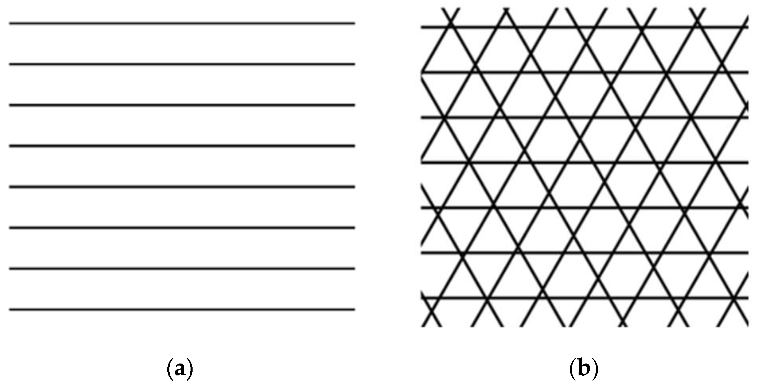
| Sample Processing Type No. | Lens (mm) | Pattern | Laser Power (W) | |
|---|---|---|---|---|
| 1 | 34 | Lines | 2 | 100 |
| 2 | 34 | Lines | 3 | 100 |
| 3 | 100 | Triangles | 3 | 180 |
| 4 | 100 | Triangles | 2.5 | 120 |
| Processing Type No. | Lens (mm) | Pattern | Measured Spacing Distance | |
|---|---|---|---|---|
| 1 | 34 | Lines | 53.0 2.7 | 115 6 |
| 2 | 34 | Lines | 63.0 3.2 | 115 |
| 3 | 100 | Triangles | 46.0 2.3 | 163 8 |
| 4 | 100 | Triangles | 39.6 2.0 | 107 5 |
| Chemical Modifier | Processing Type No. | Pattern | Lens (mm) | ||
|---|---|---|---|---|---|
| None | None | None | None | 0.39 0.14 | 1.9 0.1 |
| 1 | Lines | 34 | 3.80 0.18 | 13.8 | |
| 2 | Lines | 34 | 4.97 | 17.7 | |
| 3 | Triangles | 100 | 2.70 | 13.3 | |
| 4 | Triangles | 100 | 2.60 | 11.6 | |
| SILOX1 5 wt.% | None | None | None | 1.02 0.08 | 7.1 0.5 |
| 1 | Lines | 34 | 6.67 | 24.4 | |
| 2 | Lines | 34 | 7.80 0.58 | 29.5 | |
| 3 | Triangles | 100 | 3.90 0.32 | 18.3 1.5 | |
| 4 | Triangles | 100 | 2.46 | 11.8 0.8 | |
| SILOX2 5 wt.% | None | None | None | 1.07 0.09 | 7.1 0.3 |
| 1 | Lines | 34 | 6.30 0.69 | 24.9 2.1 | |
| 2 | Lines | 34 | 8..58 | 31..1 | |
| 3 | Triangles | 100 | 3.85 0.61 | 17.8 2.5 | |
| 4 | Triangles | 100 | 2.89 0.31 | 14.4 1.3 | |
| SILOX3 5 wt.% | None | None | None | 1.04 0.06 | |
| 1 | Lines | 34 | 7.80 0.36 | 29..5 | |
| 2 | Lines | 34 | 8.90 0.57 | 34.4 1.6 | |
| 3 | Triangles | 100 | 3.63 0.72 | 16.9 2.9 | |
| 4 | Triangles | 100 | 2.94 0.20 | 14.0 |
| Chemical Modifier | Processing Type No. | Pattern | Lens (mm) | Contact Angle (°) | Advancing Contact Angle (°) | Receding Contact Angle (°) | Contact Angle Hysteresis (°) |
|---|---|---|---|---|---|---|---|
| None | None | None | None | 90 | 102 5 | 68 4 | 34 |
| 1 | Lines | 34 | 100 3 | 113 6 | 81 | 32 1 | |
| 2 | Lines | 34 | 103 3 | 116 6 | 83 | 33 | |
| 3 | Triangles | 100 | 116 3 | 120 6 | 89 | 31 1 | |
| 4 | Triangles | 100 | 90 | 95 5 | 62 | 33 | |
| SILOX1 5 wt.% | None | None | None | 101 3 | 111 | 90 | 21 1 |
| 1 | Lines | 34 | 129 4 | 137 | 123 | 14 1 | |
| 2 | Lines | 34 | 135 4 | 143 | 117 | 26 1 | |
| 3 | Triangles | 100 | 112 3 | 119 | 90 5 | 29 1 | |
| 4 | Triangles | 100 | 123 4 | 131 | 104 | 27 1 | |
| SILOX2 5 wt.% | None | None | None | 96 3 | 108 | 87 | 21 1 |
| 1 | Lines | 34 | 113 3 | 118 6 | 88 | 30 1 | |
| 2 | Lines | 34 | 130 4 | 141 6 | 117 | 24 1 | |
| 3 | Triangles | 100 | 101 3 | 109 6 | 69 4 | 40 | |
| 4 | Triangles | 100 | 103 3 | 112 | 84 | 28 1 | |
| SILOX3 5 wt.% | None | None | None | 104 3 | 110 | 88 5 | 22 1 |
| 1 | Lines | 34 | 126 4 | 133 | 116 | 17 1 | |
| 2 | Lines | 34 | 132 4 | 142 5 | 134 6 | 8 1 | |
| 3 | Triangles | 100 | 113 3 | 119 6 | 90 | 29 | |
| 4 | Triangles | 100 | 118 4 | 125 6 | 98 | 27 1 |
| Chemical Modifier | Processing Type No. | Pattern | Lens (mm) | Ice Adhesion (kPa) |
|---|---|---|---|---|
| None | None | None | None | 346 17 |
| 1 | Lines | 34 | Break | |
| 2 | Lines | 34 | Break | |
| 3 | Triangles | 100 | Break | |
| 4 | Triangles | 100 | Break | |
| SILOX1 | None | None | None | 253 |
| 1 | Lines | 34 | Break | |
| 2 | Lines | 34 | Break | |
| 3 | Triangles | 100 | Break | |
| 4 | Triangles | 100 | Break | |
| SILOX2 | None | None | None | 417 21 |
| 1 | Lines | 34 | Break | |
| 2 | Lines | 34 | Break | |
| 3 | Triangles | 100 | Break | |
| 4 | Triangles | 100 | Break | |
| SILOX3 | None | None | None | 271 14 |
| 1 | Lines | 34 | Break | |
| 2 | Lines | 34 | Break | |
| 3 | Triangles | 100 | Break | |
| 4 | Triangles | 100 | Break |
| Chemical Modifier | Processing Type No. | Pattern | Freezing Delay Time | CA (°) | IA (kPa) | ||
|---|---|---|---|---|---|---|---|
| None | None | None | 3 min 20 s | 90 | 0.39 0.14 | 1.9 0.1 | 347 |
| SILOX1 5 wt.% | None | None | 18 min 54 s | 101 3 | 1.02 0.08 | 7.1 0.5 | 253 13 |
| SILOX1 5 wt.% | 1 | Lines | 23 min 42 s | 129 ± 4 | 6.67 | 24.4 | Break |
| SILOX1 5 wt.% | 2 | Lines | 21 min 32 s | 135 ± 4 | 7.80 0.58 | 29.5 | Break |
| SILOX1 5 wt.% | 3 | Triangles | >1 h 20 min | 112 3 | 3.90 0.32 | 18.3 1.5 | Break |
| SILOX1 5 wt.% | 4 | Triangles | 18 min 37 s | 123 4 | 2.46 0.17 | 11.8 0.8 | Break |
Publisher’s Note: MDPI stays neutral with regard to jurisdictional claims in published maps and institutional affiliations. |
© 2020 by the authors. Licensee MDPI, Basel, Switzerland. This article is an open access article distributed under the terms and conditions of the Creative Commons Attribution (CC BY) license (http://creativecommons.org/licenses/by/4.0/).
Share and Cite
Kozera, R.; Przybyszewski, B.; Krawczyk, Z.D.; Boczkowska, A.; Sztorch, B.; Przekop, R.E.; Barbucha, R.; Tański, M.; Garcia-Casas, X.; Borras, A. Hydrophobic and Anti-Icing Behavior of UV-Laser-Treated Polyester Resin-Based Gelcoats. Processes 2020, 8, 1642. https://0-doi-org.brum.beds.ac.uk/10.3390/pr8121642
Kozera R, Przybyszewski B, Krawczyk ZD, Boczkowska A, Sztorch B, Przekop RE, Barbucha R, Tański M, Garcia-Casas X, Borras A. Hydrophobic and Anti-Icing Behavior of UV-Laser-Treated Polyester Resin-Based Gelcoats. Processes. 2020; 8(12):1642. https://0-doi-org.brum.beds.ac.uk/10.3390/pr8121642
Chicago/Turabian StyleKozera, Rafał, Bartłomiej Przybyszewski, Zuzanna D. Krawczyk, Anna Boczkowska, Bogna Sztorch, Robert E. Przekop, Robert Barbucha, Mateusz Tański, Xabier Garcia-Casas, and Ana Borras. 2020. "Hydrophobic and Anti-Icing Behavior of UV-Laser-Treated Polyester Resin-Based Gelcoats" Processes 8, no. 12: 1642. https://0-doi-org.brum.beds.ac.uk/10.3390/pr8121642