
Application of Evaporative Cooling Technology in Transformer for Mine Tunnels
by
Hualin Shi
1,2, 
Bin Xiong
1,2,*,
Xiangrong Liu
3,
Kangjie Huang
1,2,
Xinhua Cai
3 and
Guobiao Gu
1,2 1
School of Electronic Electrical and Communication Engineering, University of Chinese Academy of Sciences, Beijing 100049, China
2
Institute of Electrical Engineering (IEE) of Chinese Academy of Sciences (CAS), Beijing 100190, China
3
Jinsanjiao Electric Technology Share Co., Ltd., Wenzhou 325600, China
*
Author to whom correspondence should be addressed.
Processes 2021, 9(5), 875; https://0-doi-org.brum.beds.ac.uk/10.3390/pr9050875
Submission received: 16 April 2021
/
Revised: 10 May 2021
/
Accepted: 12 May 2021
/
Published: 17 May 2021
(This article belongs to the Special Issue Design, Concepts and Applications of Electric Machines)
Abstract
:The traditional dry-type mine transformer has some disadvantages, such as incomplete fire prevention, large volume, high loss and not enough environmental protection. Based on evaporative cooling technology, this paper proposes a scheme of mine transformer using fluorocarbon as coolant which can truly realize the incombustible transformer scheme and meet the strict environmental requirements. The transformer adopts three-dimensional wound core structure to reduce the loss and improve the anti-short-circuit ability. The volume of transformer is greatly reduced due to the efficient heat dissipation ability of evaporative cooling technology. The scheme of plate fin heat exchanger is more suitable for the ventilation condition of the mine. The filling technology is used to reduce the amount of expensive coolant. Through the life cycle cost analysis, evaporative cooling transformer has better economic benefits than traditional mine transformer, but also has better safety benefits. A prototype is manufactured and tested, and the results show that the prototype meets the requirements of IEC standard temperature rise limit and achieves the expected requirements.
1. Introduction
With the development of industry and the expansion of new energy fields, the transformer as an important piece of equipment of power domain, in addition to stability, reliability and new requirements, is put forward. The application scenarios in mine tunnels have strict requirements for fire prevention, prevention of explosions, low loss and high power density. The transformer is required to be safe and reliable in flammable, explosive, humid, dusty and poor heat dissipation conditions and other such harsh environments.
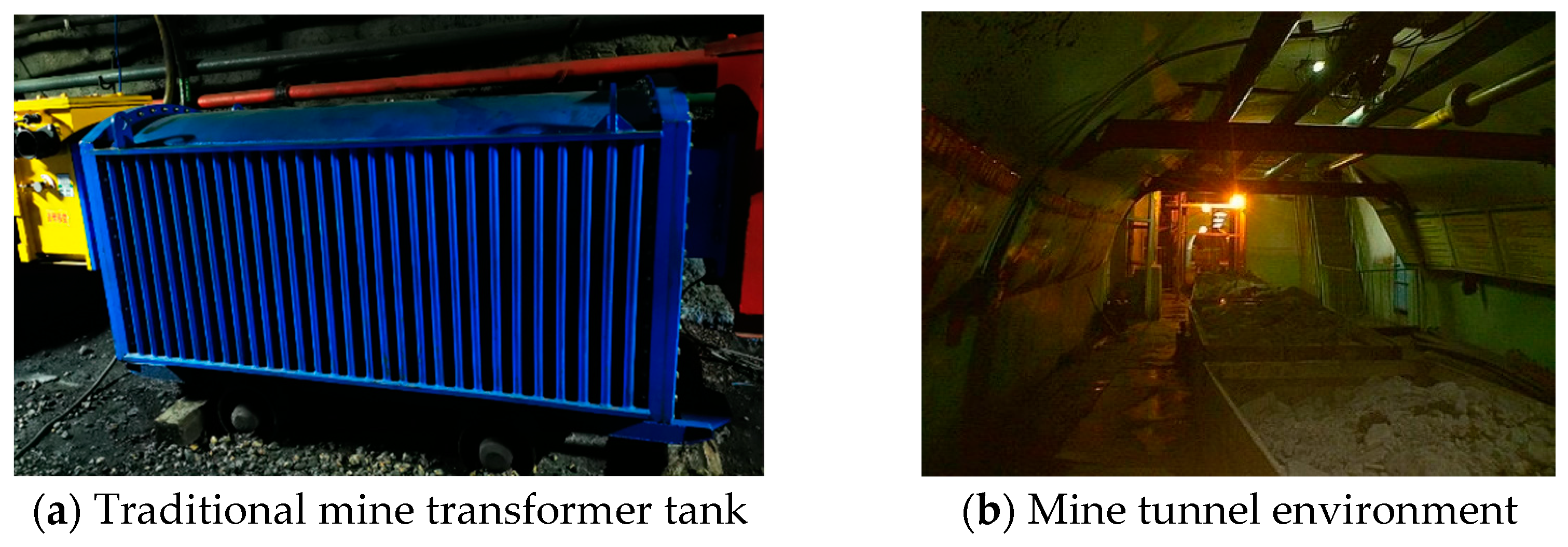
At present, dry-type transformer instead of oil immersed transformer is mostly used in places such as mine tunnels. The reason is that the insulation of the traditional oil immersed transformer is low ignition temperature and flammable, and the oil immersed transformer has no explosion-proof capability. Compared with oil immersed transformer, dry-type transformer is cooled by air and is flame retardant, but it is not non-combustible. If the temperature exceeds the limit, it will still catch fire in case of open fire. There are other inherent disadvantages such as the insulation and heat capacity of the air which when used for insulation and heat dissipation are far less than that of transformer oil. The cooling efficiency is low and the heat dissipation effect is poor, and it often needs to add a fan for auxiliary cooling. In addition, more core and coil materials are used because of the low winding current density which is about 1 A/mm2 generally. The effective materials cannot be fully utilized, and the load loss is only 3–5 times the no-load loss, so the performance is lower than that of oil immersed transformer with the same capacity. Mining flameproof transformer often uses corrugated shell to achieve heat dissipation requirements by expanding the surface area (see Figure 1a), which leads to large volume, poor overload capacity, difficulty in making large capacity and greater cost. The mine tunnels are humid and dusty (see Figure 1b), so that the surface of transformer body easily attracts coal dust to form a layer of wet mud, which worsens the poor heat dissipation capacity and leads to the decline of transformer performance. Therefore, the transformer in mine tunnels is frequently damaged with high failure rate.
In view of the requirements for fire and explosion prevention, miniaturization, low weight, low loss and high performance application of transformers in mine tunnels, this paper proposes a solution for transformer for mine tunnels based on evaporative cooling technology. Evaporative cooling technology is a new and efficient cooling technology which uses fluorocarbon organic fluid to transfer heat by phase change to cool heating parts. In the process of vaporization and condensation, the fluorocarbon coolant can realize gas–liquid two-phase circulation flow through its own thermal power conversion, and realize self-circulation without external power. Compared with mineral oil, air and other conventional cooling working fluids, it has many advantages such as high heat exchange efficiency, effective cooling performance, good insulating property, low system pressure, easy maintenance, simple operation, non-combustibility, explosion prevention, high reliability and meeting the requirements for environmental protection.
Since the 1950s, the Institute of Electrical Engineering of Chinese Academy of Sciences (IEECAS) has started to carry out the application research of fluorocarbon refrigerant evaporative cooling technology in electrical equipment. In these years, it has been successfully applied to many kinds of electrical equipment such as giant hydro generators (27 MW units and 28 MW units of Three Gorges Project) [1], large turbine generators [2], iron removers [3], power electronic devices [4,5], ion source magnet [6], super computer [7], etc. In the decades of research progress, the durability and aging resistance of fluorocarbon coolant have also been tested and a lot of engineering practice experience and technical reserves have been accumulated, which provides a solid foundation for the application of evaporative cooling technology in transformer. The evaporative cooling transformer has also been made a subject of preliminary application attempt in the early stage [8,9]. At present, the research and development of conventional evaporative cooling transformer is relatively backward because of the high cost of coolant. Therefore, the application of evaporative cooling technology in the field of transformer mainly solves a series of problems that are difficult to be solved by conventional cooling methods, such as high-speed train traction transformer [10] and marine transformer, but there is a lack of research on mine transformer.
Therefore, the research on mine transformer based on evaporative cooling technology is to meet the technical requirements of mine transformer from the perspective of excellent explosion-proof performance and strengthening heat dissipation, which has great application value and good application prospects.
2. Principle of Evaporative Cooling Transformer
2.1. Self-Circulation Evaporative Cooling System
The evaporative cooling system of the transformer is designed by full immersion of fluorocarbon compounds coolant. Different from the traditional oil immersed self-cooling distribution transformer, full immersion evaporative cooling transformer uses phase change heat transfer of fluorocarbon coolant to absorb heat generated by transformer.
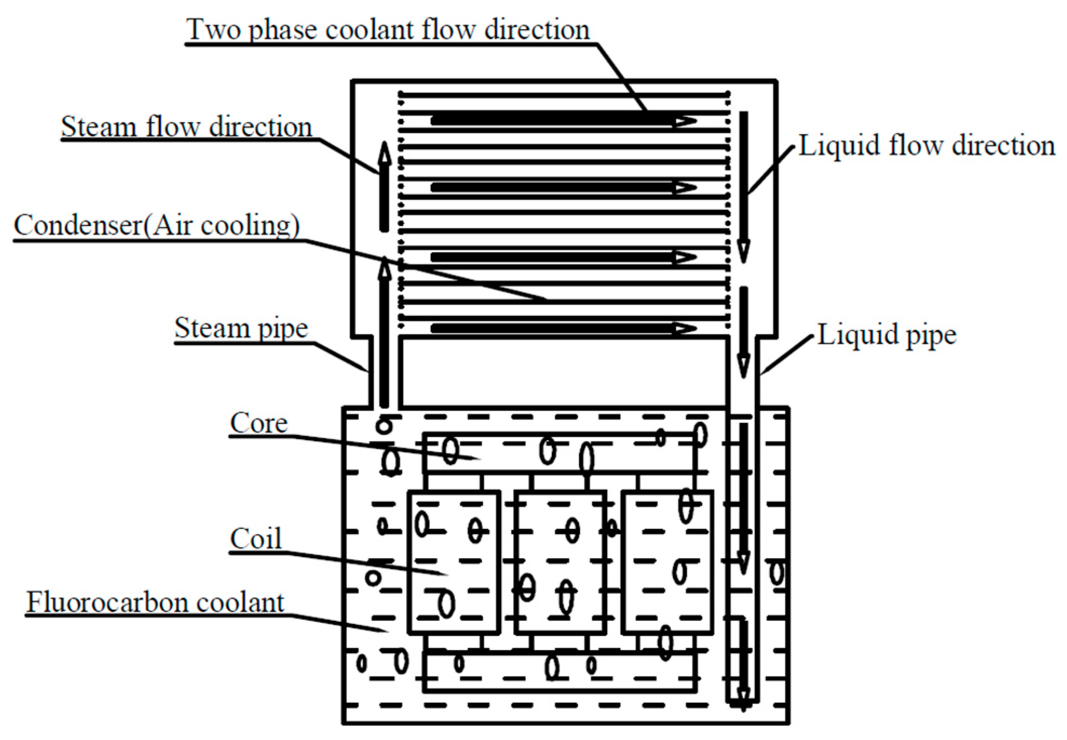
In view of its non-combustible, non-explosive, low viscosity, good insulation and heat dissipation characteristics, fluorocarbon coolant can be used as both cooling and insulation working fluids in the evaporative cooling system of transformer. The principle of self-circulation evaporative cooling is shown in Figure 2. The electromagnetic coil and the core are completely immersed in the liquid fluorocarbon evaporative cooling working fluid. The loss generated by the operation of the coil and the iron core is converted into heat, and the heat is absorbed by the liquid working fluid. When the liquid working fluid obtains the latent heat of vaporization, it vaporizes under the saturation pressure, and the gaseous working fluid flows upward through the steam pipe into the top condenser under the action of buoyancy. The working medium releases latent heat in the condenser and condenses into liquid, and the liquid working medium flows back to the tank through the liquid pipe under the action of gravity. As mentioned above, the system relies on the two-phase change heat transfer processes of fluorocarbon working fluid; that is, the liquid working fluid floats up by buoyancy after heat absorption and vaporization, and the gas working fluid flows back by gravity after condensation and liquefaction to realize the self-circulation of the cooling system without pump. The optimal energy efficiency of the cooling system is realized.
2.2. Selection and Introduction of Evaporative Coolant
Different from the coolant used in air conditioners and refrigerators, the use of coolant in electrical equipment needs to meet the electrical performance and heat source characteristics. In the past, CFC-113 was used as evaporative coolant in electrical equipment. However, CFC Freon would destroy the ozone layer, and so the new environmentally friendly fluorocarbon coolant with 0 ODP (ozone depression potential) value must be adopted, so as to ensure the popularization, application and sustainable development of evaporative cooling technology in electrical equipment. For non-combustible mining transformer, according to the working conditions and environmental protection requirements of transformer, the suitable fluorocarbon coolant should have the following properties:
- Safe, non-toxic, non-flammable, non-explosive, environmentally acceptable ODP and GWP values;
- The suitable boiling point is favorable for the rated operating temperature of transformer heating parts;
- Good insulation performance;
- Good chemical stability and compatibility with common transformer materials, the durability and aging resistance of fluorocarbon coolant have been tested and have qualified;
- Good thermal conductivity, low viscosity and low flow resistance;
- The cost is acceptable.
According to the operation characteristics of mine transformer, a kind of fluorocarbon coolant which meets the above requirements is selected, and the boiling point is 80 °C. The coolant is non-flammable and non-toxic with 0 ODP value. After at least 800 h compatibility test with common transformer materials such as masking tape, silicone fluororubber, unidirectional weftless tape, nomex paper, phenolic paperboard, epoxy board, corrugated paper and so on, the chemical and electrical insulation properties of the coolant and materials remain stable. The insulation withstands voltage of the coolant: 53.9 kV before 800 h compatibility test and 46.9 kV after compatibility test.
The comparison of the physicochemical and electrical performance parameters of the fluorocarbon coolant with the common insulating liquids such as transformer oil is shown in Table 1.
The results are shown in Table 1. The breakdown voltage and specific heat capacity of fluorocarbon coolant are slightly weaker than those of transformer oil, but the kinematic viscosity is only 6% that of transformer oil which means that the heat transfer cycle of the fluorocarbon working fluid is much faster than that of transformer oil. The latent heat of vaporization is large enough to make the heat exchange capacity much stronger than that of the transformer oil. According to the further high-voltage test, the breakdown voltage of gaseous or two-phase fluorocarbon is about one third of that of pure liquid state, but under 10 kV voltage level, it is enough to meet the requirements of breakdown voltage standard of the transformer for fluorocarbon coolant in pure liquid phase or two-phase state.
3. Transformer Design
3.1. Design Principles
The design principle of the evaporative cooling transformer is as follows:
- Meet the mine’s explosion-proof, low loss and small volume requirements;
- The cooling system design of evaporative cooling transformer should be based on the electromagnetic scheme of oil immersed self-cooling distribution transformer;
- The design should be suitable for mine environmental conditions;
- Meet the test requirements of evaporative cooling transformer.
3.2. Electromagnetic Scheme of Transformer
According to the design principle, the electromagnetic scheme is designed based on the electromagnetic parameters of a 250 kVA oil immersed self-cooling transformer, and the parameters are shown in Table 2. The design requires the transformer to have 315 kVA overload capacity; that is, the actual load loss is 3830 W, the rated current of high and low voltage coils is 16.16 A and 405.05 A, respectively, and the current density is 2.46 A/mm2 and 3.241 A/mm2, respectively. The ratio of load loss to no-load loss is as high as 13.88.
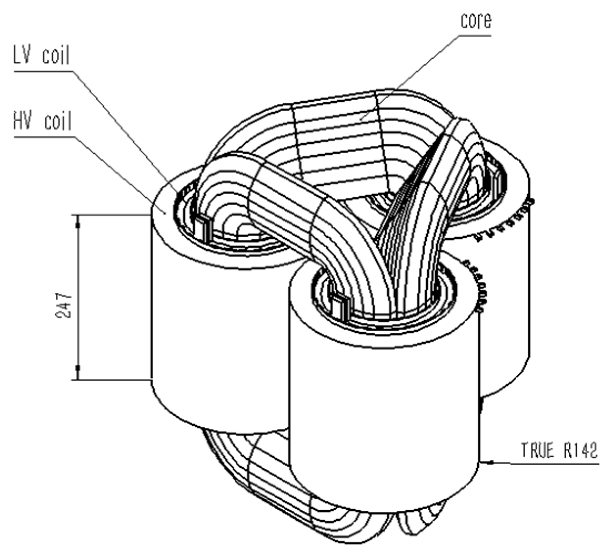
In order to meet the requirements of low loss, the scheme of three-dimensional core winding is selected. There are many advantages that have been proposed for transformer with three-dimensional wound core and it has found increasing application in China and Iran [11]. The results show that there is no seam between the core layers of the three-dimensional wound core transformer, the magnetic circuit is evenly distributed and there is no obvious high-resistance area, the magnetic flux direction is consistent with the crystal orientation of the silicon steel sheet, the length of the three-phase magnetic circuit is completely the same and symmetrical and the three-phase no-load current is completely balanced. Compared with the traditional planar laminated core transformer, under the same capacity condition, the three-dimensional wound core transformer has the advantages of saving silicon steel material, being lightweight, small volume, small no-load loss, low noise, low cost, superior mechanical and electrical performance [12,13]. Taking S13-250 kVA transformer as an example, the no-load loss standard of oil immersed self-cooling laminated core is 290 W, while the no-load loss of three-dimensional wound core can generally reach below 276 W. The structure of the coil and core is shown in Figure 3.
3.3. Design of Cooling System
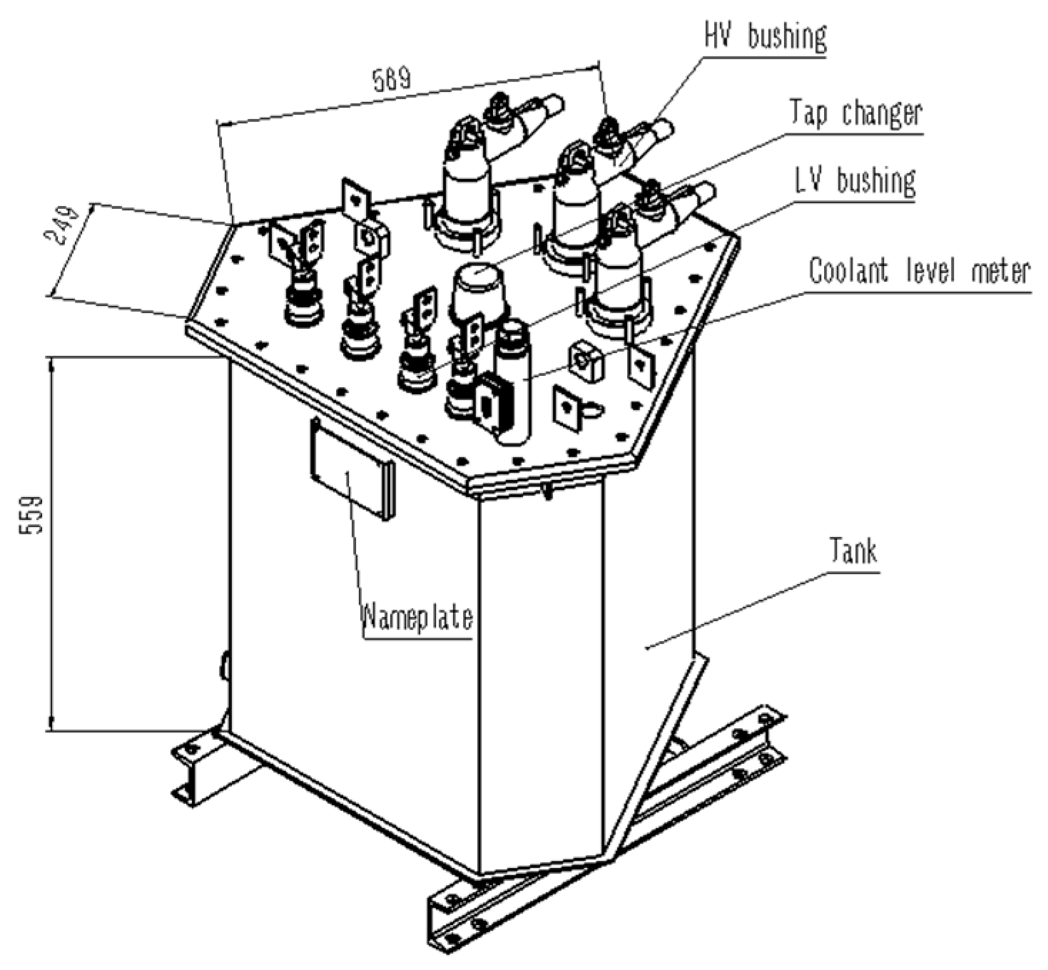
The space of mine tunnels is narrow, so the transformer has the requirements of being lightweight and small volume. The size of the transformer is especially required to reduce the transverse size. The evaporative cooling working fluid can efficiently absorb the heat generated by the core and coil, and realize heat exchange with the external environment through the condenser. Therefore, the corrugated fins of the conventional tank have been removed, and the transverse size is reduced by 50%. Compared with the corrugated tank of mine dry-type transformer, the volume is greatly reduced. In order to ensure the safe insulation distance between high-voltage joints and condenser, elbow joints are used. See Figure 4 for transformer tank.
There is a significant feature of the mine tunnels that the large fan runs for a long time and the horizontal ventilation is very large. According to this characteristic, the plate fin heat exchanger with vertical arrangement is adopted in the design of condenser, and the horizontal ventilation is conducive to the heat dissipation of condenser fins. The inner fins circulate coolant, and the outer fins circulate air.
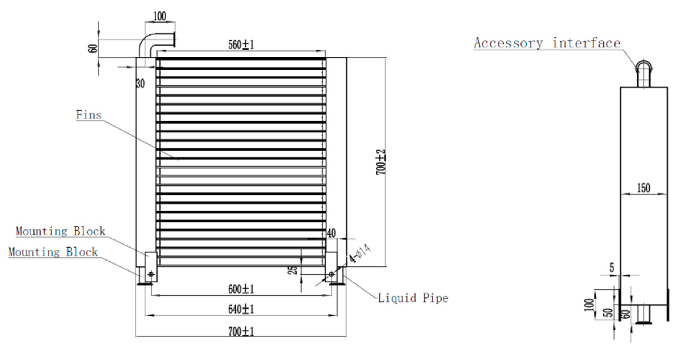
The standard values of no-load loss and load loss of S13-250 kVA oil immersed self-cooling distribution transformer are 290 W and 3200 W, respectively, and the transformer is required to achieve 315 kVA load capacity, of which no-load loss and load loss are 340 W and 3830 W, respectively. The total loss of 4170 W can be regarded as the calorific value of the transformer. Taking the margin coefficient of 1.2, the designed total heat load of the condenser is 5000 W. It is designed according to the steam temperature of inlet pipe 80 °C and liquid temperature of return pipe 75 °C. The design pressure is atmospheric pressure, and there is a safety valve connection on the top of the condenser. The product size is 700 × 700 × 150 mm, as shown in Figure 5. The inner fins are serrated fins with a height of 3 mm, a thickness of 0.2 mm and a pitch of 2.5 mm; the outer fin is corrugated, 6.5 mm in height, 0.15 mm in thickness and 2 mm in pitch. The heat transfer area of the evaporative coolant is 29 m2, and that of the air side is 58 m2.
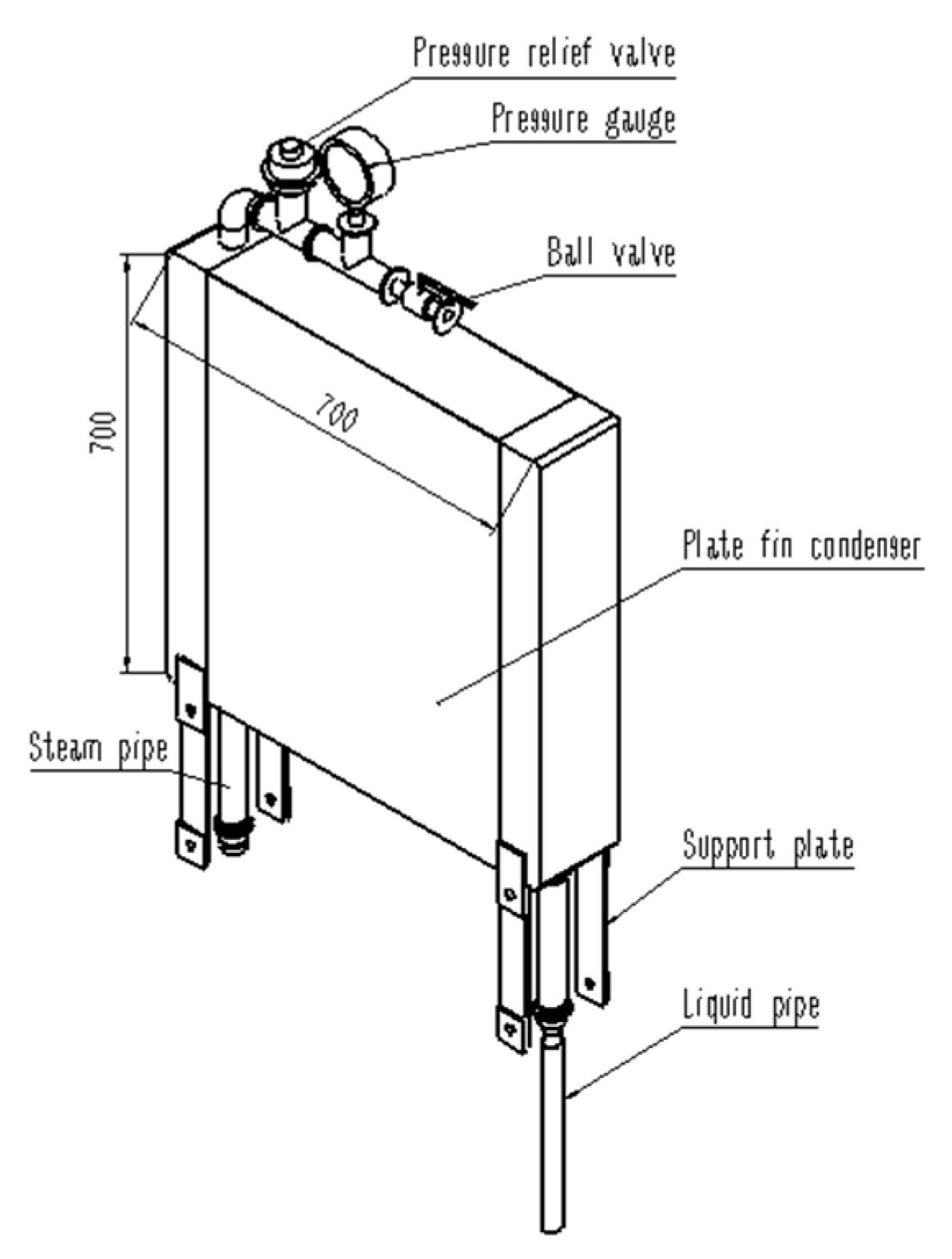
In order to ensure the normal and stable operation of the self-circulating evaporative cooling system, a safety valve, a pressure gauge and a ball valve are arranged on the top of the condenser. The ball valve is used as the interface of air tightness test, and the pressure gauge is convenient to detect the system pressure. When the pressure is greater than 35 kpa, the safety valve will start to release the pressure and keep the system pressure safe and stable. When the system is started for the first time, there is a lot of air in the system. Because the air density is lower than the steam density, it will adhere to the condenser. The air is non-condensing gas under the working condition of transformer, which will cause the decrease of heat transfer coefficient. The performance is that the pressure is higher than the design value, and the operating temperature also increases. For the evaporative cooling system, it is best to keep the condenser near zero gauge pressure, so it is necessary to exhaust at the beginning or when the pressure is high. After exhausting the non-condensing air, the system will enter the stable operation stage.
3.4. Design of Filling Structure of the Tank
The oil tank structure (excluding corrugated fins) is designed according to 250 kVA oil transformer, so the tank space is designed according to the oil consumption. In the evaporative cooling system, only the coil and core are needed to immerse into the coolant. The heat transfer performance by phase change of fluorocarbon coolant is excellent, and it does not need to fill the whole tank. The price of fluorocarbon working fluid is very expensive (200–400 yuan/kg, about $31.1–62.2), so reducing the amount of expensive fluorocarbons also needs to be taken into account as much as possible.
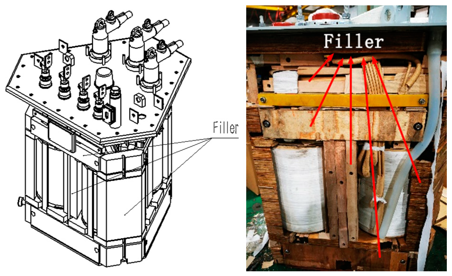
Therefore, based on the requirement of lightweight design of transformer tank structure, the insulation material with lower density can be used to fill the unnecessary space in the tank which is not heated. These materials, called fillers, not only meet the thermal and electrical properties, but are also required to be low cost and environmentally friendly. Based on the theoretical research and practical engineering experience of evaporative cooling technology, hollow wood block, laminated wood, epoxy board, etc. which have passed the compatibility test are used as fillers, which will not affect the cooling effect of evaporative coolant, and will not change the performance of fillers.
In order to form a space conducive to the flow of the evaporative cooling working medium to the top heat exchanger and the condensation reflux, the filler should surround the coil and core. The gap between filler and heat source presents a vertical narrow shape. The filler structure is shown in Figure 8. In the process of filling installation, the mechanical strength should be ensured, and the original state should be kept when the coolant is boiling. The filler structure can greatly reduce the consumption of fluorocarbon coolant on the premise of ensuring the insulation performance between the core and the winding. According to the heat transfer calculation and the actual filling effect, the consumption of working fluid was reduced from 191 kg to 130 kg, saving 61 kg coolant, which means saving 12,200 yuan (about $1897), and the total cost of coolant is reduced by 31.9%. The volume of fluorocarbon working fluid is about half of the original transformer oil.
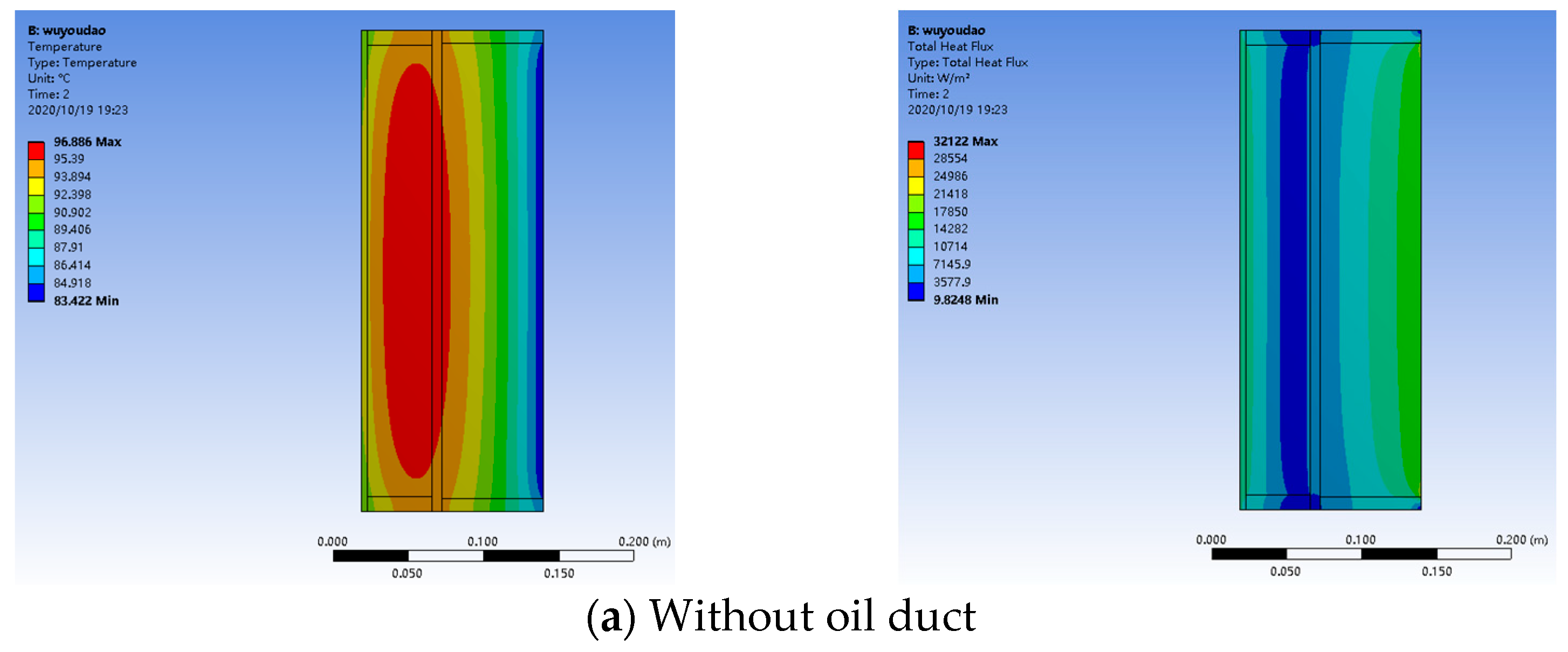
3.5. Simplified Calculation of Coil Temperature and Design of Oil Duct
The high-voltage and low-voltage coil are the layer windings, which contain conductor, coating, insulation, etc. The thermal conductivity is treated by equivalent thermal resistance of conductor and insulation. The overall thermal conductivity is treated by equivalent thermal conductivity of copper and inter turn insulation. The calculation formula of equivalent thermal conductivity is as follows.
where r and x are wire gauge and inter turn insulation thickness of conductor, respectively; λCu and λjy are thermal conductivity of copper and inter turn insulation, respectively. In this scheme, wire gauge of high-voltage winding is different from that of low-voltage winding; enameled round copper wire is selected for high-voltage winding and enameled flat copper wire is selected for low-voltage winding.
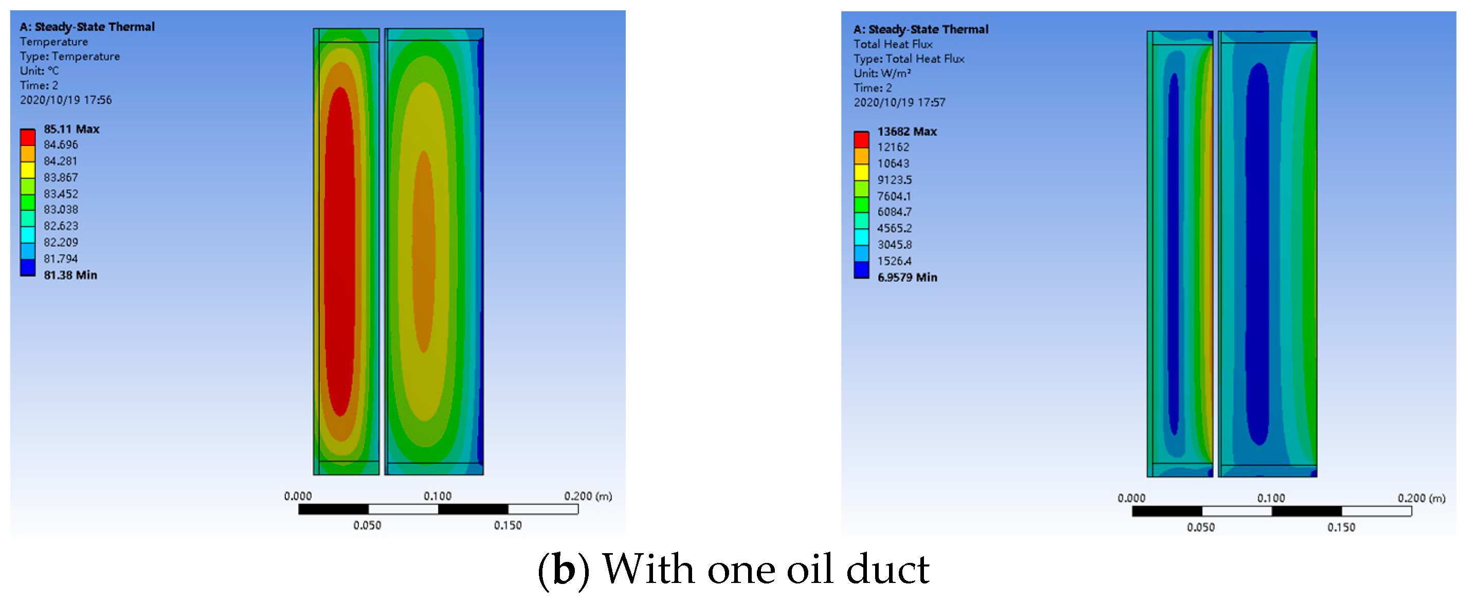
According to the simulation diagram Figure 9, even if there is no oil duct between the high- and low-voltage coils, the maximum coil hot spot temperature is 96.886 °C, which can meet the requirements of IEC 60076.2 temperature rise limit. However, the traditional oil immersed self-cooling distribution transformer with the same capacity needs to arrange three oil ducts in total. In this design, only one oil duct is arranged between the high- and low-voltage coils, which reduces the complexity of coil winding process.
3.6. Benefit Analysis
Oil immersed transformers are not suitable for special occasions with strict fire protection requirements, even transformers with high ignition point such as vegetable oil. As mentioned in the introduction, dry-type transformer can only be flame-retardant transformer. Epoxy resin used as insulation usually has a maximum ignition point of 550 °C, which is not non-combustible material. Therefore, the current transformer scheme has defects for the occasions with strict fire protection requirements, and the fluorocarbon solution scheme can truly realize the incombustible transformer scheme, and its safety benefit is inestimable.
The life cycle cost of transformer includes investment cost, operation cost, maintenance cost and decommissioning disposal cost.
(1) Investment cost
Table 3 shows the price of main materials of transformer in China. Taking the design of evaporative cooling transformer prototype as an example, the cost of copper, silicon steel and other materials is the same as that of 250 kVA oil immersed self-cooling distribution transformer, the consumption of working medium is 130 kg (26,000 yuan, about $4043), the price of condenser is about 3000 yuan (about $466.50) and the price of the transformer is about 54,000 yuan (about $8397).
Table 4 shows the prices of 315 kVA transformers in China. The designed evaporative cooling transformer can reach the capacity of 315 kVA. From the comparison in Table 4, it can be seen that the price of the evaporative cooling transformer is almost the same as that of the traditional mine transformer. However, the volume of the transformer is 50% smaller than that of the traditional mine transformer with the same capacity, and it has better explosion-proof performance and heat dissipation performance.
(2) Operation cost
It is known from the introduction that the ratio of load loss to no-load loss of mining transformer is only 3–5, while it is known from Chapter 3.2 that the ratio of load loss to no-load loss of evaporative cooling transformer is as high as 13.88. Therefore, the evaporative cooling transformer has lower loss than the general mine transformer, which means lower operating cost, and better economy in the long run.
(3) Maintenance cost including failure cost
Through decades of application of evaporative cooling technology in large-scale electrical equipment, including Three Gorges hydro generator, it has been shown that evaporative cooling technology has extremely low maintenance costs and low failure rate. Therefore, we infer that the maintenance costs and failure rate of evaporative cooling mine transformer will not be higher than that of traditional mine transformer.
(4) Decommissioning disposal cost
At present, all countries pay attention to environmental protection, and the cost of decommissioning disposal is mainly environmental disposal cost. The biodegradability of traditional transformer mineral oil is poor (less than 30%), which is a kind of non-environmental protection liquid insulation material. Once leakage occurs, it will cause serious pollution to the environment, so its environmental protection disposal cost is high. Epoxy resin, as the insulating material of dry-type transformer, cannot be biodegradable after being scrapped, so it will be called the stubborn garbage of nature. If it is burned, it will produce a large number of carcinogens, causing human health hazards and environmental pollution. Therefore, the cost of decommissioning is very high under China’s strict environmental protection policy. As the insulating fluid of evaporative cooling transformer, fluorocarbon coolant, meets the requirements of environmental protection and is harmless to people and the environment, the cost of decommissioning is far less than that of traditional oil transformer and dry transformer.
By comprehensive comparison, the evaporative cooling mine transformer has better safety, economic and environmental benefits than the traditional mine transformer.
4. Prototype Test
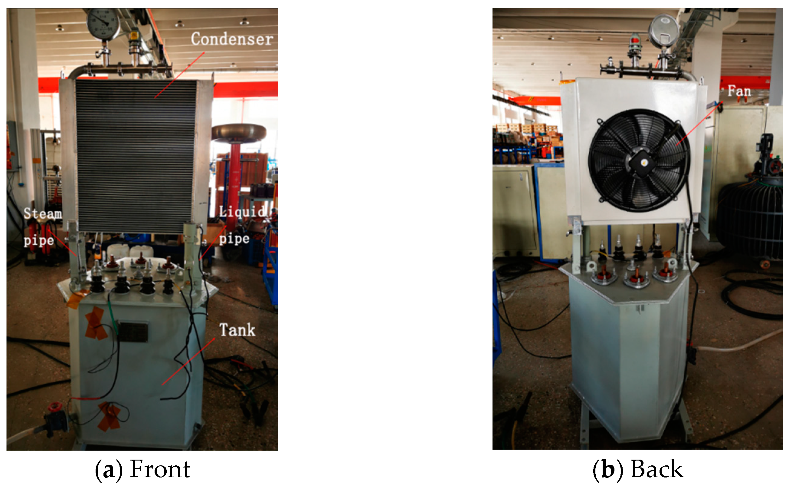
According to the theoretical analysis and calculation, the prototype is designed and manufactured as shown in Figure 10. In order to meet the explosion-proof requirements, the oil tank adopts the form of fully enclosed welding.
The short circuit method is used to test the temperature rise of evaporative cooling transformer. The steady state temperature rise test results of Table 5 show that the top oil temperature rise and the average winding temperature rise are 23.9 °C and 61 °C under 1.26 overload factor, which meet the requirements of IEC 60076.2 temperature rise limit. The experiment verified that compared with the heat transfer system of the conventional oil immersed transformer, the fluorocarbon coolant has better heat transfer and heat dissipation ability due to its excellent flow performance, small kinematic viscosity and phase change heat transfer. Because the fluorocarbon coolant in the whole immersion evaporation cooling system can fully exchange heat with the heating parts in the system, the temperature field distribution in the cooling system is uniform and the temperature rise of local hot spot is relatively low, so the local overheating problem is avoided. The system can drive the automatic operation of the whole cooling system through the pressure difference formed by evaporation and condensation reflux of fluorocarbon coolant. The transformer has excellent overload performance, and the whole system has the characteristics of low noise, low cost of operation and maintenance.
5. Discussion
In order to further optimize the performance of the transformer, it is necessary to carry out relevant research on the two-phase flow condensation heat exchanger, further study the design of 3300 V, 1140 V, 660 V and other mining electrical systems and further study the explosion-proof structure of evaporative cooling transformer. At the same time, it is also necessary to conduct more in-depth exploration and research on evaporative cooling technology and its related theory of the transformer.
6. Conclusions
In this paper, based on the phase change heat transfer characteristics of fluorocarbon coolant, the design and research of fully immersed evaporative cooling transformer in mine tunnels are carried out. The cooling system can realize self-circulation without additional power equipment such as pump. Electromagnetic scheme design is based on oil immersed self-cooling three-dimensional wound core distribution transformer for reducing the no-load loss and improving the ability of anti-short-circuit. According to the characteristics of horizontal ventilation in mine tunnels, the natural condensation scheme of plate fin heat exchanger is adopted. The corrugated fins are eliminated to reduce the transverse space, and the filler technology is used in the transformer to reduce the dosage of the coolant. Through the simulation calculation, the single oil duct between the high- and low-voltage coils is designed, and the prototype is made to verify that the transformer meets the requirements of IEC temperature rise limit.
According to the life cycle cost analysis, compared with the conventional mine tunnels explosion-proof corrugated dry transformer, the mine transformer with evaporative cooling technology can not only eliminate the fire hazard completely, but also has smaller volume and better economy. This research has guiding significance for the engineering application of evaporative cooling transformer in the field of mining transformer, traction transformer, marine transformer and special transformer with strict non-combustible requirements for buildings.
Author Contributions
Writing—review and editing, H.S.; project administration, B.X.; funding acquisition, X.L.; validation, K.H.; data curation, X.C., supervision and inspection, G.G. All authors have read and agreed to the published version of the manuscript.
Funding
This research was funded by Jinsanjiao Electric Technology Share Co., Ltd.
Institutional Review Board Statement
Not applicable.
Informed Consent Statement
Not applicable.
Data Availability Statement
The study did not report any data.
Acknowledgments
Associate researcher Xiong Bin for experimental platform designing assistance.
Conflicts of Interest
The funders had no role in the design of the study; in the collection, analyses, or interpretation of data; in the writing of the manuscript, or in the decision to publish the results.
References
- Guobiao, G.; Lin, R. Applications and Developments of the Evaporative Cooling Technology in the Field of Hydrogenerators. Proc. CSEE 2014, 34, 5112–5119. [Google Scholar] [CrossRef]
- Jianhong, G.; Guobiao, G.; Deping, F.; Deshu, H. Cooling Characteristics and Performance of the 330 MW Evaporative Cooling Turbo Generator. Trans. China Electrotech. Soc. 2013, 28, 134–139. [Google Scholar]
- Hui, G.; Fuchuan, S.; Jiayi, Y.; Shuke, L. The Research of the Evaporative Cooling Electromagnetic Iron-separator. Proc. CSEE 2006, 26, 60–65. [Google Scholar]
- Luan, F.F.; Yu, S.Z.; Guo, J.H.; Wang, H.F. Application of evaporative cooling technology in high power rectifier devices. Power Syst. Technol. 2009, 33, 137–142. [Google Scholar]
- Wei, H.; Wei, F.; Haifeng, W.; Biao, C.; Jingjie, Y. Simulation and experimental study on the evaporative cooling system of HVDC valve unit. Trans. China Electrotech. Soc. 2017, 32, 264–270. [Google Scholar]
- Bin, X.; Lin, R.; Guobiao, G.; Shuqin, G.; Rui, C.; Zhenguo, L.; Wang, L.; Xuezhen, Z.; Hongwei, Z.; Liangting, S. Development of higher power density evaporativecooling magnet coils in ECR ion source. Electr. Mach. Control 2016, 20, 22–28. [Google Scholar] [CrossRef]
- Guo, S.Q.; Ruan, L.; Li, Z.G.; Liu, F.H. The design of controlling system in the evaporative cooling super computer simulation experiment platform based on PLC. In Applied Mechanics and Materials; Trans Tech Publications Ltd.: Freienbach, Switzerland, 2013; Volume 437, pp. 734–739. [Google Scholar]
- Niu, W.; Li, N.; Xu, Z.; Jin, C.; Bai, Z.; Zhong, H.; Zhang, G. Preliminary study of the evaporative cooling cast resin transformers. In Proceedings of the 2012 China International Conference on Electricity Distribution, CICED 2012, Shanghai, China, 10–14 September 2012. [Google Scholar]
- Niu, W.; Li, N.; Chen, S.; Tang, S.; Hu, Y.; Cai, J.; Lv, L.; Jin, C.; Bai, Z.; Zhong, H.; et al. Experimental study of the evaporative cooling system in a low-noise power transformer. In Proceedings of the 2012 China International Conference on Electricity Distribution, CICED 2012, Shanghai, China, 10–14 September 2012. [Google Scholar]
- Bin, X.; Zi-Ran, C.; Yu-Feng, Z. Research on key technologies of evaporative cooling traction transformer of vehicle. Adv. Technol. Electr. Eng. Energy 2020, 39, 1–5. [Google Scholar] [CrossRef]
- Elhaminia, P.; Hajipour, E.; Moradnouri, A.; Vakilian, M. Derivation of a low-frequency model for a 3D wound core transformer. In Proceedings of the 2017 Iranian Conference on Electrical Engineering (ICEE), Tehran, Iran, 2–4 May 2017. [Google Scholar]
- Peng, C.; Yongming, Y.; Xiaoyun, Z.; Fan, Y.; Chunli, L.; Wei, H. Calculation and analysis of three-dimensional temperature field of dry-type transformer with tridimensional wound core. Transformer 2013, 50, 12–15. [Google Scholar]
- Shu, N.; Tao, J.; Gang, Y.; Xiaozhen, S.; Jiangjun, R.; Yongqing, D. Thermal-fluid field analysis of 10 kV oil immersed stereoscopic coil core transformer. Electr. Meas. Instrum. 2019, 1–7. Available online: http://kns.cnki.net/kcms/detail/23.1202.th.20200927.1706.006.html (accessed on 13 May 2021).
Figure 1.
Environment of the mine tunnels and the conventional mine transformer.

Figure 2.
Schematic diagram of transformer evaporative cooling technology.

Figure 3.
Core and coil structure of three-dimensional wound core transformer.

Figure 4.
Design of evaporative cooling transformer tank.

Figure 5.
Condenser design drawing.

Figure 6.
Assembly diagram of plate fin condenser.

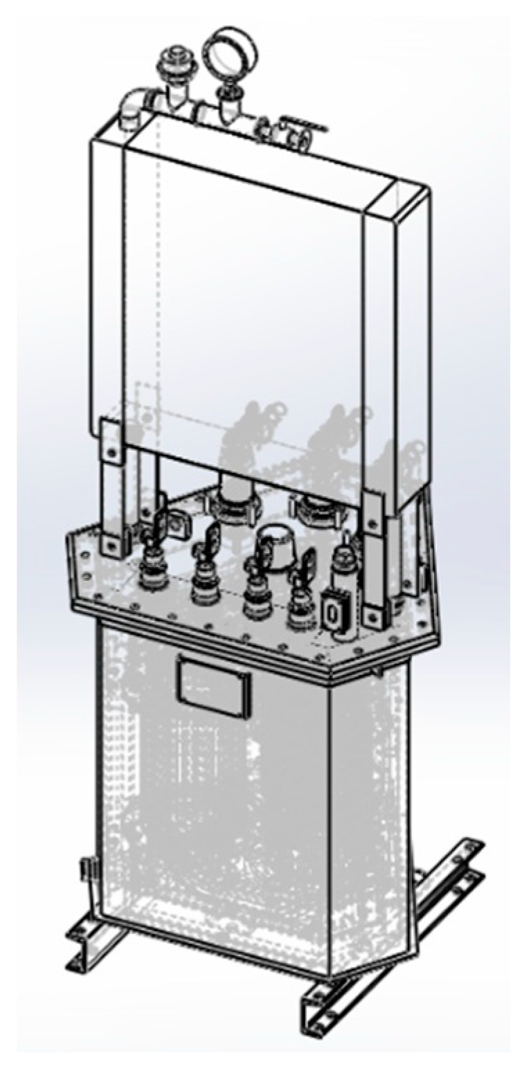
Figure 7.
Design drawing of evaporative cooling transformer.

Figure 8.
Filler design and actual filling effect.

Figure 9.
Filler design and actual filling effect.


Figure 10.
Prototype of evaporative cooling transformer for mine tunnels.


Table 1.
Performance comparison of selected fluorocarbon coolant and other insulating coolant.
| Parameter | I-10 °C Transformer Oil | CFC-113 | The Fluorocarbon Coolant |
|---|---|---|---|
| Breakdown voltage [kV/2.5 mm] | 60 | 37 | 53.9 |
| Dielectric constant | 2.2 | 2.44 | 1.87 |
| Boiling point [°C] | - | 47.6 | 80 |
| Density [g/cm3] | 0.86 | 1.56 | 1.69 |
| Kinematic viscosity [mm2/s] | 16 | 0.44 | 0.97 |
| Specific heat (liquid) [kJ/(kg·°C)] | 1.89 | 0.904 | 1.225 |
| Latent heat of vaporization [kJ/kg] | - | 149.7 | 85.8 |
| Thermal conductivity [W/(m·K)] | 0.131 | 0.076 | 0.064 |
| Remarks | Measured at 25 °C,1 atm | ||
Table 2.
Parameters of transformer.
| Parameters | Value |
|---|---|
| Rated voltage [kV] | 10/0.4 |
| Rated current [A] | 14.4/360.85 |
| Rated frequency [Hz] | 50 |
| No-load loss [W] | 276 |
| Load loss [W] | 3086 |
| Short circuit impedance | 4.10% |
| Vector Group Symbol | Dyn11 |
| Magnetic flux density of Core [T] | 1.66 |
| Magnetic flux density of Yoke [T] | 1.78 |
| Current density [A/mm2] | 2.192/2.887 |
Table 3.
Main material price of transformer.
| Material | Price [yuan/kg] | Price [USD/kg] |
|---|---|---|
| copper | 60 | 9.33 |
| Silicon steel | 18 | 2.80 |
| transformer oil (I-10 °C) | 7 | 1.09 |
| The fluorocarbon coolant | 200 | 31.10 |
Table 4.
Price of 315 kVA transformers.
| 315 kVA Transformer Type | Price [yuan] | Price [USD] |
|---|---|---|
| Oil immersed self-cooling transformer | 25,000 | 3887.50 |
| Ordinary dry-type transformer | 30,000 | 4665 |
| Traditional mine dry-type transformer | 50,000 | 7775 |
| Fluorocarbon evaporative cooling transformer | 54,000 | 8397 |
Table 5.
Steady state temperature rise test.
| Load Factor | Ambient Temperature/°C | Top-Oil Temperature Rise/°C | Average Winding Temperature Rise/°C |
|---|---|---|---|
| 1 | 18.8 | 20.5 | 47.7 |
| 1.26 | 18.8 | 23.9 | 61.0 |
Publisher’s Note: MDPI stays neutral with regard to jurisdictional claims in published maps and institutional affiliations. |
© 2021 by the authors. Licensee MDPI, Basel, Switzerland. This article is an open access article distributed under the terms and conditions of the Creative Commons Attribution (CC BY) license (https://creativecommons.org/licenses/by/4.0/).
Share and Cite
MDPI and ACS Style
Shi, H.; Xiong, B.; Liu, X.; Huang, K.; Cai, X.; Gu, G. Application of Evaporative Cooling Technology in Transformer for Mine Tunnels. Processes 2021, 9, 875. https://0-doi-org.brum.beds.ac.uk/10.3390/pr9050875
AMA Style
Shi H, Xiong B, Liu X, Huang K, Cai X, Gu G. Application of Evaporative Cooling Technology in Transformer for Mine Tunnels. Processes. 2021; 9(5):875. https://0-doi-org.brum.beds.ac.uk/10.3390/pr9050875
Chicago/Turabian StyleShi, Hualin, Bin Xiong, Xiangrong Liu, Kangjie Huang, Xinhua Cai, and Guobiao Gu. 2021. "Application of Evaporative Cooling Technology in Transformer for Mine Tunnels" Processes 9, no. 5: 875. https://0-doi-org.brum.beds.ac.uk/10.3390/pr9050875
Note that from the first issue of 2016, this journal uses article numbers instead of page numbers. See further details here.