
Effect of Tip Clearance on Helico-Axial Flow Pump Performance at Off-Design Case


Key Laboratory of Fluid and Power Machinery, Ministry of Education, Xihua University, Chengdu 610039, China
*
Authors to whom correspondence should be addressed.
Processes 2021, 9(9), 1653; https://doi.org/10.3390/pr9091653
Submission received: 30 June 2021
/
Revised: 8 September 2021
/
Accepted: 9 September 2021
/
Published: 13 September 2021
Abstract
:To reveal the effect of tip clearance on the flow behaviors and pressurization performance of a helico-axial flow pump, the standard k-ε turbulence model is employed to simulate the flow characteristics in the self-developed helico-axial flow pump. The pressure, streamlines and turbulent kinetic energy in a helico-axial flow pump are analyzed. Results show that the tip leakage flow (TLF) forms a tip-separation vortex (TSV) when it enters the tip clearance and forms a tip-leakage vortex (TLV) when it leaves the tip clearance. As the blade tip clearance increases, the TLV moves along the blade from the leading edge (LE) to trailing edge (TE). At the same time, the entrainment between the TLV and the main flow deteriorates the flow pattern in the pump and causes great hydraulic loss. In addition, the existence of tip clearance also increases the possibility of TLV cavitation and has a great effect on the pressurization performance of the helico-axial flow pump. The research results provide the theoretical basis for the structural optimization design of the helico-axial flow pump.
1. Introduction
Compared with the traditional gas–liquid separation and transportation methods, multiphase transportation technology has some obvious advantages and broad application prospects in offshore and onshore crude oil transportation [1,2]. The helico-axial flow pump, as the core equipment for multiphase transportation technology, has become hot spots in recent years because of its large wrap angle, long passage, and characteristics suitable for gas–liquid transportation [3,4,5]. There is relative motion between the impeller blade tip and the shroud, and the pressure difference between the pressure side (PS) and suction side (SS) provides the power. Then, the tip leakage flow (TLF) near the blade tip appears [6,7]. Next, the tip leakage vortex (TLV) occurs [8,9]. The TLV increases the hydraulic loss in the passage and weakens the hydraulic performance and efficiency, even causing vibration and noise, which has a considerable effect on the operation stability of pumps [10,11,12,13].
The tip clearance affects the flow behaviors and performance of pumps, thus many scholars have conducted investigations on the tip clearance.
In terms of axial-flow pumps, Shi et al. [14,15] studied the effect of blade tip clearance on velocity characteristics of a multiphase pump. In the tip clearance case, a low-velocity region appeared in the impeller shroud. Meanwhile, with the aggrandizement of the blade tip clearance, the gas primarily accumulated at the hub, the SS, and the tip gaz. To investigate the effect of tip clearance on hydrodynamic characteristics of a water-jet propulsion pump, Han et al. [16] used a numerical simulation method to conduct the study. With the augmentation of tip clearance, the saddle curve slowed down and the leakage also increased. Similarly, considering the tip-clearance effect, Shen et al. [17] unmasked the flow characteristics in an axial-flow pump. When tip clearances became larger, TLV was increased and obviously affected the main flow. Based on experimental and simulation approaches, Xu et al. [18] studied the TLV cavitation at different tip clearances. With the augmentation of blade tip clearance, the effect of TLV on pressure near the blade tip was increased, and the position and intensity of TLV cavitation were different.
Mixed-flow pumps are also important types of fluid machinery and play a major role in the national economy. Ji et al. [19] investigated the flow behaviors and the hydraulic losses in mixed-flow pumps. When the tip clearance was from 0.2 mm to 1.1 mm, the head loss increased 1.62 times. On account of the SST k-ω model, Zhang et al. [20] also revealed the flow behaviors in a mixed-flow pump. With an increase in clearance size, leakage was also increased leading to energy loss. Based on particle image velocimetry (PIV) measurement, Li et al. [21] studied the flow fields in a pump with nonuniform blade tip clearance. Because of the nonuniform tip clearance, the secondary flow in the pump impeller was increased and a vortex was formed. Meanwhile, the relative velocity near the hub was increased. Ji et al. [22] used the experimental method to study the effect of blade tip clearance on pressure pulsation. With the augmentation of blade tip clearance, high-value wavelet spectrum expanded to a low-frequency direction, and the second-order peaks in the time-averaged wavelet curve were easily formed.
In addition to axial-flow pumps and mixed-flow pumps, investigation on centrifugal pumps is also extensive. Parikh et al. [23] took advantage of numerical and experimental methods to investigate the effect of blade tip clearance on gas–liquid two-phase flow in a pump. The increased tip clearance led to enhancements in performance and mixing. Under five different tip clearances, Zhang et al. [24] simulated the flow field in a centrifugal pump. As the clearance decreased, the strength of the TLV was weakened, and the secondary TLV in the mainstream channel gradually disappeared. Cui et al. [25] also revealed the blade tip clearance effect on the performance of a pump. With augmentation of blade tip clearance, the relative velocity and static pressure in the clearance were reduced at the middle and blade TE, especially the relative velocity.
The effect of blade tip clearance on the flow behaviors in pumps is mainly analyzed as above. As power machinery, the stability of pumps is very important. The unsteady flow in the blade tip region can induce pressure fluctuation, resulting in an increase in axial force and radial force. At the same time, noise and vibration intensify. Hao et al. [26] proposed that symmetrical tip clearance affects the magnitude of radial force. In addition, cavitation occurs in blade tip clearance and affects the pressure fluctuation. Meanwhile, cavitation accumulates in the tip region and reduces axial flow. Tip clearance can advance cavitation and increase the amplitude of pressure pulsation [27]. Sometimes, clearance flow produces strong, unsteady, exciting force, the frequency of which coincides with the natural frequency of the impeller under certain working conditions, causing resonance and fatigue fracture of the blade.
The change of operating conditions also affects tip clearance flow. Tip clearance is sometimes very sensitive to the change of working conditions, and the influence of tip clearance is sometimes obvious once there is a change of working conditions. Especially with a small flow rate, the hydraulic performance will change more [28]. In short, the effect of tip clearance is very complex and there are many factors affected.
Tip-clearance effect has been studied extensively in pumps as well as in other machines. In the literature [29,30,31], the effect of tip clearance on the performance of other turbomachinery was also investigated.
Based on the above research results, many researchers have conducted a lot of investigations on axial-flow pumps, mixed pumps, centrifugal pumps, and other types of fluid machinery. However, the investigation has not been sufficient. Meanwhile, the investigations on the helico-axial flow pump at low flow-rate are inadequate. In order to improve the efficiency of helico-axial flow pumps, the study of flow in pumps is imminent. The effect of blade tip clearance on flow is an inevitable research direction. In view of this situation, the standard k-ε turbulence model is used to investigate the effect of blade tip clearance on the axial-flow pump performance. By analyzing the flow state in the pump, the effect law of blade tip clearance is summarized. The findings provide the theoretical basis for the structural design, loss reduction, and efficiency improvement of helico-axial flow pumps.
2. Physical Model of a Helico-Axial Flow Pump
3. Helico-Axial Flow Pump Test Rig
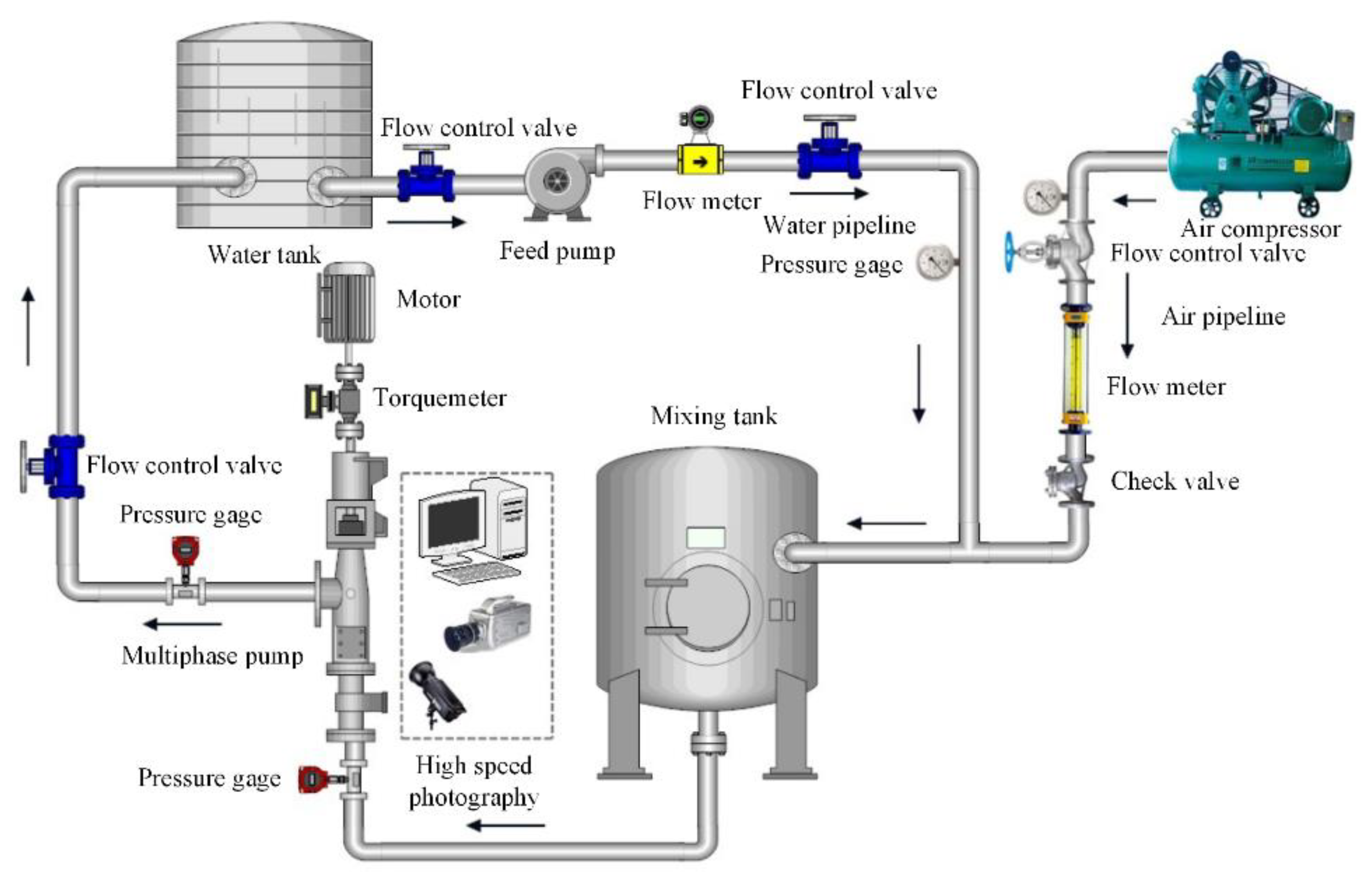
Figure 2 is a helico-axial flow pump test rig and is mainly composed of a helico-axial flow pump, motor, gas–liquid mixing tank, control system, water supply system, lubrication system, gas supply system, cooling system, pipelines, and valves. The main equipment used in the test are shown in Table 2. The uncertainty is conducted and equal to 0.4671%.
4. Numerical Methods and Verification
4.1. Governing Equation
The flow in the helico-axial flow pump is a very complex three-dimensional turbulent state, but it also obeys the basic governing equations. Heat transfer is not considered in the calculation process, so the energy equation is involved. The continuity equation and momentum equation are as follows
Continuity equation:
where u, v, and w represent the velocity components of the velocity vector in the x, y, and z directions, respectively.
Momentum equation:
where ρ is the fluid density, t is the time, and is the velocity vector. u, v and w represent the velocity components of the velocity vector in the directions of x, y, and z, respectively. τx, τy, and τz are the viscous components acting on the surface of the element due to molecular viscous action. Fx, Fy, and Fz are the physical force of the element.
4.2. Mesh Arrangement
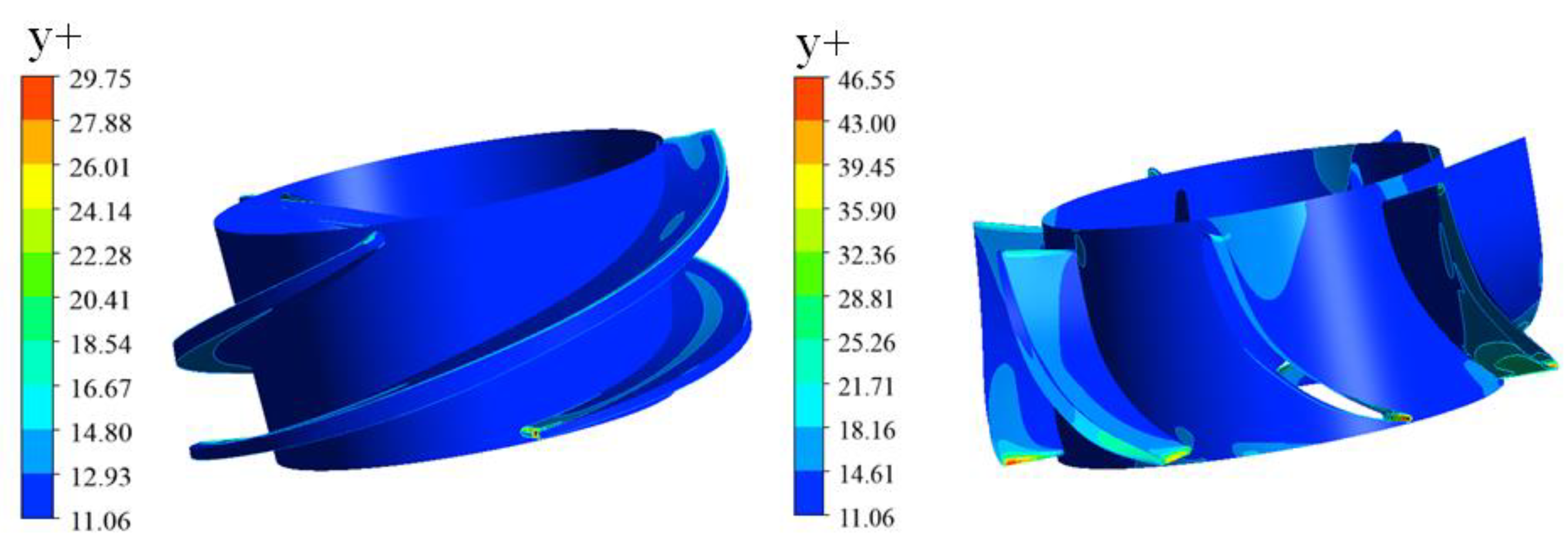
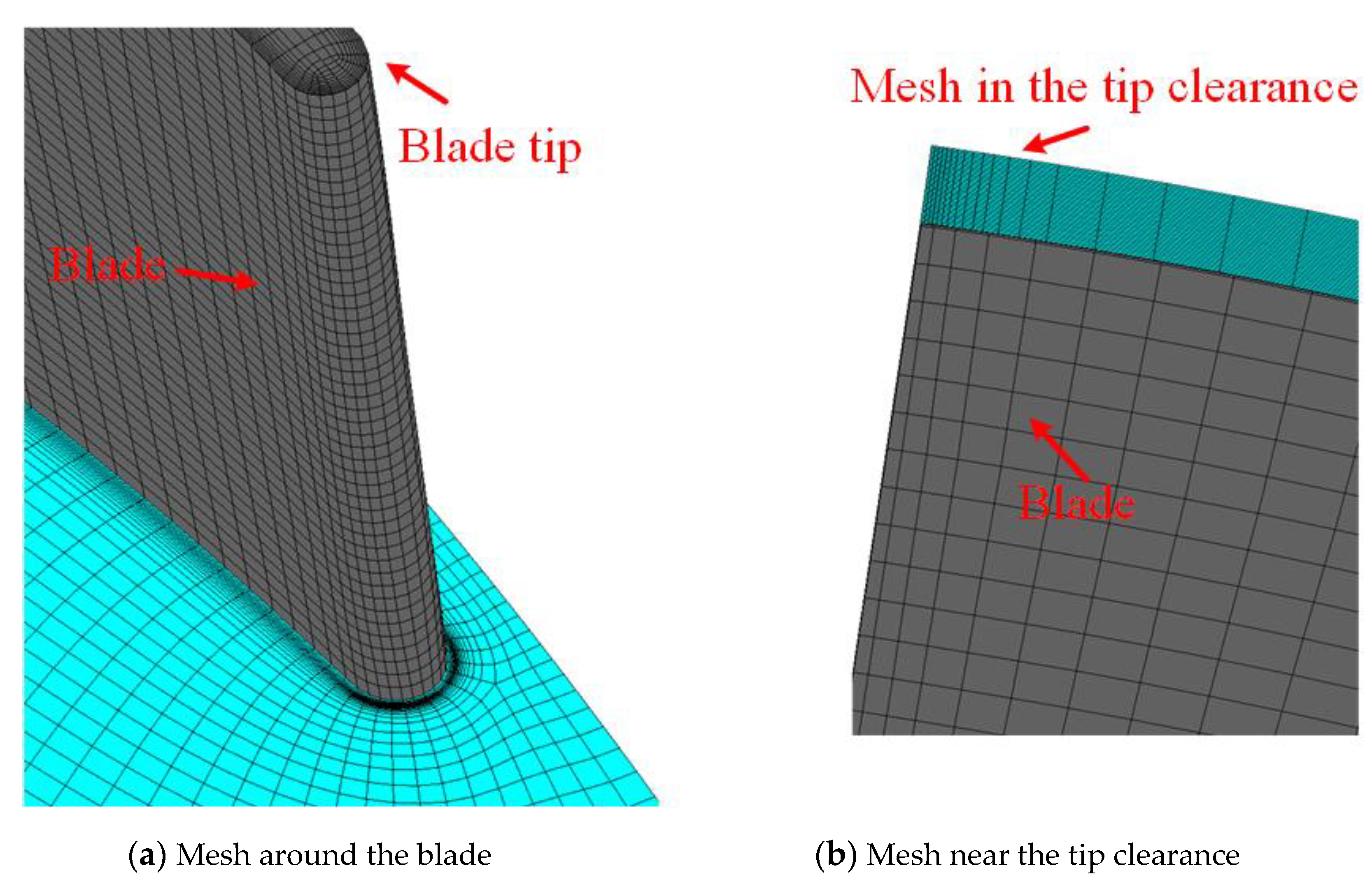
In consideration of the convergence and accuracy in the numerical simulations, hexahedral structured mesh is adopted for the entire computation domain. To accurately control the boundary layer mesh near the blade, the O-topology method is used for the impeller and diffuser [32]. Meanwhile, the local mesh around the blade is refined. The flow structure near the blade tip clearance is more complicated. To precisely capture the flow behaviors in detail, 20 nodes at any rate are set from the blade tip to shroud. The mesh quality of the impeller and diffuser is greater than 0.33 and 0.45, respectively. In addition, in Figure 3 the y+ values of the impeller and diffuser are less than 30 and 47, respectively, which meet the standard k-ε turbulence model. The specific computation domain mesh is shown in Figure 4.
4.3. Mesh Independence Verification
Mesh number has a great effect on the numerical simulation. If the mesh number is too small, it will cause inaccuracy in the flow solution. If the mesh number is too large, it will increase the computational cost. Therefore, the mesh independence verification is performed in this section and displayed in Table 3 and Table 4.
In Table 4, the error head and efficiency between different mesh numbers is very small. Considering the simulation accuracy and calculation cost, mesh 4 is finally selected.
4.4. Numerical Method and Setting
Based on Reynolds-averaged Navier–Stokes equations (RANS) as well as the standard k-ε turbulence model, the software platform ANSYS CFX is used to calculate the flow state in helico-axial flow pump at a steady condition.
The transport equations of k and ε in the standard k-ε turbulence model are as follows.
The model constants are as follows: C1ε = 1.44, C2ε = 1.92, σk = 1.0, σε = 1.3.
The fluid medium is water and the basic parameters are as shown in Table 5.
The boundary conditions at the pump inlet and outlet are set as normal speed and pressure outlet, respectively. The flow rate and the inflow area at the inlet are adopted to calculate the velocity at the inlet. Meanwhile, the pressure at the helico-axial flow pump outlet is set to 6 atm. In addition, the rotational speed, the reference pressure, and the flow rate are set to 3000 rpm, 101,325 Pa and 80 m3/h, respectively. The no-slip wall is also selected, and the wall function is set as scalable. When root mean square (RMS) residual is lower than 1 × 10⁻⁵ and the pressure difference at the pump inlet and outlet is stable, the calculation is considered to be convergent.
4.5. Numerical Validation
The computational fluid dynamics (CFD) and experimental flow fields are shown in Figure 5 and used to verify the reliability. For better comparison of simulation and experimental results, the same color is used to distinguish them. The TLV in the experiment is in good agreement with the CFD’s. Therefore, the numerical method is reliable.
5. Results and Discussion
5.1. Parameter Definition
In order to disclose the flow behaviors along the radial direction, the nondimensional parameter, the radial coefficient r* is proposed. The r* at the hub and the shroud is 0 and 1, respectively. Meanwhile, the dimensionless distance between the impeller inlet and the impeller outlet is defined, that is, the impeller inlet is 0 and the impeller outlet is 1.
5.2. Helico-Axial Flow Pump Performance
Figure 6a,b are the helico-axial flow pump head and efficiency, respectively. From Figure 6a, without the tip clearance, the head is gradually decreased as the flow rate increases. The head trough occurs at 60 m3/h, that is, the saddle curve appears. The presence of the tip clearance results in reduction of the head, and as the blade tip clearance grows, the head is dramatically decreased. Meanwhile, blade tip clearance leads to the disappearance of the saddle curve. For Figure 6b, without the blade tip clearance, the best efficiency point (BEP) is about 70% and at 100 m3/h. As the blade tip clearance grows, efficiency is gradually reduced. When the blade tip clearance is equal to 1.5 mm, the efficiency is reduced to about 40%. The tip clearance has an important impact on performance, thus the tip clearance selection and reasonable design are crucial for helico-axial flow pump performance improvement.
5.3. Pressure on Blade Surface
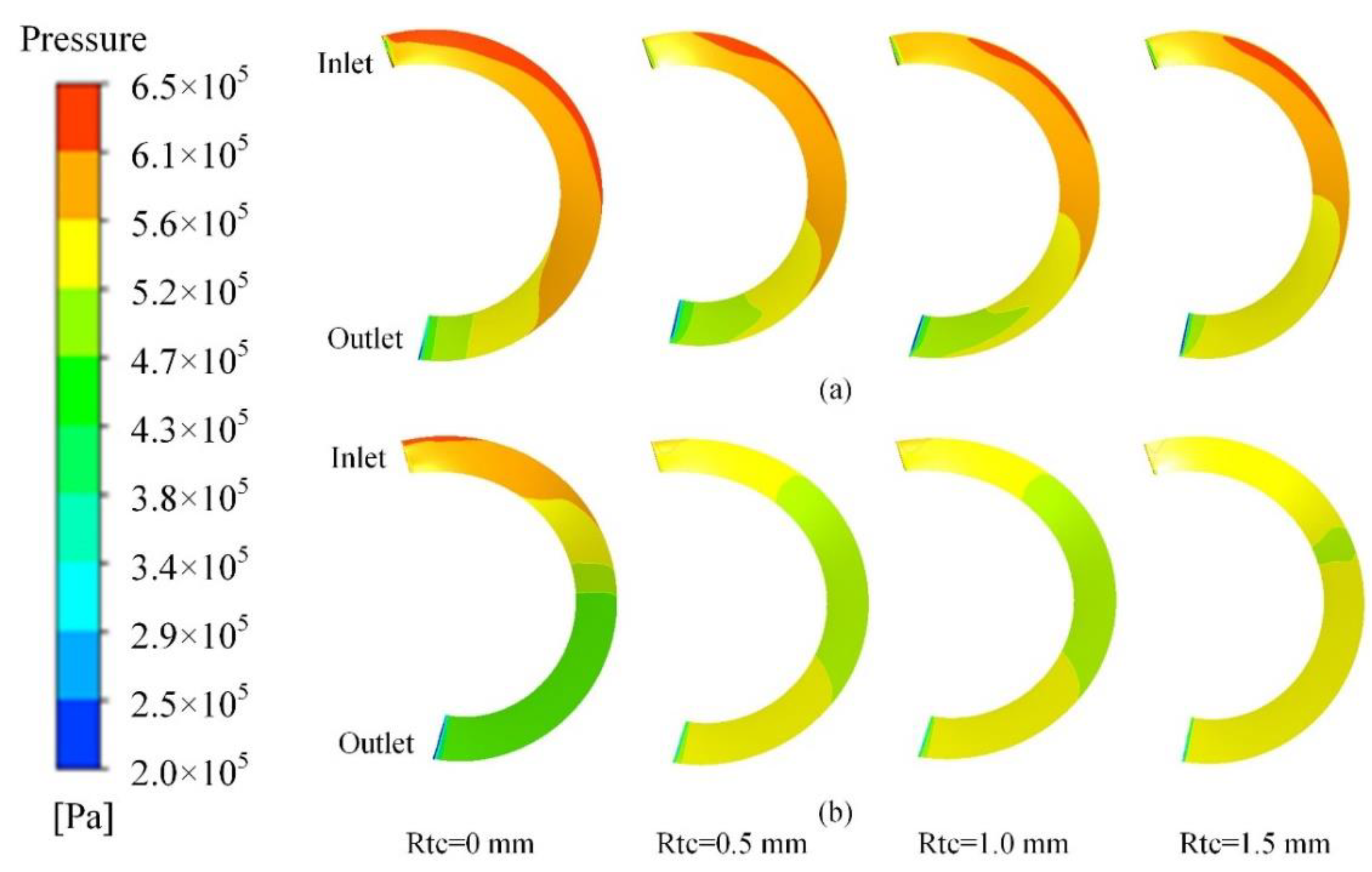
Figure 7a,b are pressure on PS and SS, respectively. For Figure 7, when the blade tip clearance is 0 mm, the pressure on PS and SS is gradually augmented from the blade inlet to the outlet. The pressure gradient is also large, which indicates that pump pressurization effect on the fluid is better. The high-pressure region at the PS outlet is not extended to the blade outlet with blade tip clearance. The high-pressure region is smaller. Meanwhile, as the blade tip clearance augments, the low-pressure area near blade inlet is steadily reduced and closed to the blade inlet. The high-pressure area is gradually extended to the blade middle. In addition, the pressure variation on the SS is clearer. The pressure at the blade inlet and outlet is greater. The pressure at the blade middle is lesser. When the blade tip clearance is increased, the high-pressure area at SS inlet and outlet is extended to the blade middle. The low-pressure area at the blade inlet is gradually decreased. The helico-axial flow pump pressurization performance is gradually deteriorated as the blade tip clearance increases. When the blade tip clearance is 1.5 mm, the pressurization performance at the blade inlet is poor, which is most obvious.
5.4. Impeller Radial Pressurization Performance along Flow Direction
To analyze the impeller radial pressurization performance along the flow direction, the radial pressure difference between the flow coefficient (impeller middle along flow direction) of 0.5 and the flow coefficient (near impeller inlet) of 0.1 is shown in Figure 8. In Figure 8, the flow coefficient and radial coefficient are described clearly. The same method is performed for the radial pressure difference from the impeller middle to outlet, and the numerical simulations are displayed in Figure 9a,b.
In Figure 9a, when the blade tip clearance is 0 mm, the pressurization performance from impeller inlet to middle is gradually increased. However, as the blade tip clearance grows, the pressurization performance is gradually decreased and becomes the same along the radial direction. Moreover, the pressurization performance near the blade tip is dramatically weakened as the blade tip clearance rises. This indicates that the existence of blade tip clearance reduces the power capability near the blade tip.
For Figure 9b, when the blade tip clearance is 0 mm, the pressurization performance gradually becomes stronger from the hub to the radial coefficient of 0.8, and weaker from the radial coefficient of 0.8 to the shroud. When the blade tip clearance rises from 0.5 mm to 1.0 mm, the pressurization performance gradually becomes stronger. As the tip clearance increases, the pressurization performance gradually becomes stronger from the hub to the radial coefficient of 0.6, and weaker from the radial coefficient of 0.6 to the shroud. Impeller radial pressurization performance is about the same from the hub to the radial coefficient of 0.6 when the blade tip clearance is 1.5 mm. However, the impeller radial pressurization performance from the radial coefficient of 0.6 to the shroud is weaker than that in the 1.0 mm case. Meanwhile, the pressurization performance near the tip is slightly stronger than at the other locations. Moreover, the impeller radial pressurization performance from the impeller inlet to middle is greater than that from the impeller middle to outlet. An order of magnitude of difference exists when the blade tip clearance is 0 mm. The radial pressurization performance difference is gradually reduced as the blade tip clearance grows. The blade-tip-clearance effect on the radial pressurization performance between the impeller inlet to middle and the impeller middle to outlet is different. The variation progress of the radial pressurization performance is also different. On the one hand, the degree of the TLV is different, and on the other hand, the pressurization capacity in different parts of the impeller is different. The effect of blade tip clearance on the pump pressurization performance is complex, and the further investigations on the pressurization process are of great significance for revealing the working mechanism of the helico-axial flow pump.
5.5. Pressure, Velocity, and Streamlines near the Blade Tip along the Circumferential Direction
Figure 10, Figure 11 and Figure 12 display the pressure, velocity, and streamlines at the impeller radial coefficient of 0.9, respectively. From Figure 10, when the blade tip clearance is 0 mm, the pressure gradient from the impeller inlet to outlet is dramatically changed. The local high-pressure region near the impeller outlet is also visible. When the tip clearance is presented, the pressure gradient from the impeller inlet to the outlet is rarely changed. When the blade tip clearance grows, the high-pressure area in the impeller flow passage is gradually decreased. The pressure difference point between the blade PS and SS gradually moves from LE to TE. The pressure difference is the power, which is formed by TLV. Therefore, as the pressure difference moves to TE, TLV also moves to TE. The phenomenon is observed more clearly at tip clearances of 1.0 mm and 1.5 mm. The greater the blade tip clearance is, the greater TLF occurs. This has a significant impact on pressure inside the impeller.
Due to installation error, bearing wear, and mechanical vibration, the tip clearance is varied which impacts the flow field in the helico-axial flow pump. Therefore, more attention should be paid to the tip clearance variation case.
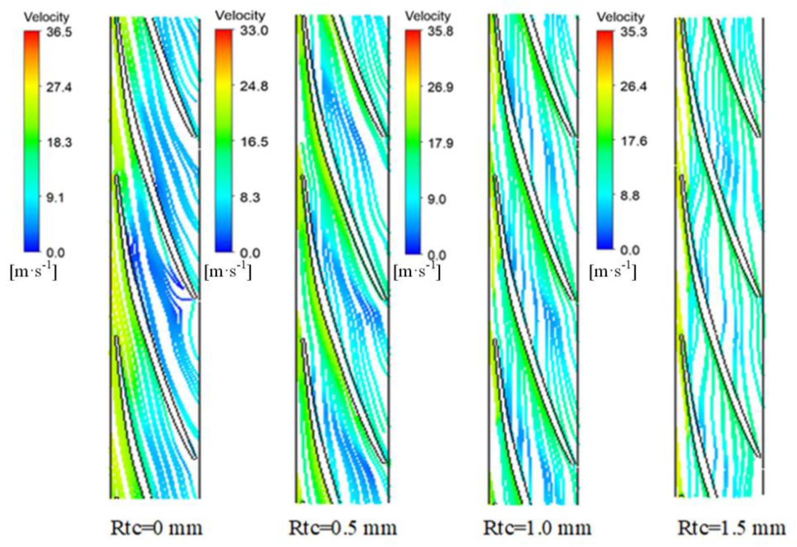
For Figure 11, velocity uniformity becomes worse when the blade tip clearance is 0 mm. When there is tip clearance it is obviously improved. The high-velocity region at the impeller inlet is larger when the blade tip clearance is 0 mm. With the existence of tip clearance it is significantly smaller. As the blade tip clearance rises, the high-velocity region becomes larger. The TLF and main flow are entrained in the tip area, which causes energy loss. The low-velocity area appears in the tip area. When the blade tip clearance rises, the jet effect weakens and the entrainment effect of TLV and main flow weakens. The low-velocity area is also improved.
In Figure 12, when the blade tip clearance is 0 mm, the streamlines from the impeller inlet to the outlet are smooth. The flow patterns in the flow passage are stable. When the blade tip clearance rises, the TLF is increased and interacts with main flow. The streamlines are deflected along the circumferential direction, which is more obvious at the tip clearance of 1.5 mm. As the blade tip clearance increases, the leakage near the tip plays the leading role in the tip area, which affects the flow pattern near the tip area. The research on velocity characteristics provides reference for the clearance design.
5.6. Turbulent Kinetic Energy in the Impeller and Diffuser
Figure 13 presents the kinetic energy in the impeller and diffuser meridional plane. As shown in Figure 13, the turbulent kinetic energy in the pump impeller and diffuser is relatively low. The kinetic energy loss in the diffuser is slightly larger than that in the impeller. When the blade tip clearance rises, the turbulent energy in the impeller is increased. The maximum turbulent energy gradually moves along the flow direction. The entrainment of TLV and main flow deteriorates the flow pattern and causes greater hydraulic loss. The greater the turbulent kinetic energy, the stronger the effect of the TLV becomes. At the same time, the maximum turbulent kinetic energy moves in the impeller passage, which indicates that the TLV is also moving. This is consistent with the analysis in Figure 10. With the growth of blade tip clearance, the turbulent kinetic energy in the diffuser is steadily decreased, which is more obvious at the diffuser inlet and middle along the flow direction. Compared with the impeller, the turbulent kinetic energy in the diffuser is lower because the diffuser is a stationary part and has a rectifying effect.
5.7. TLV Characteristics
To clearly analyze the flow characteristics in tip clearance, tip clearance is divided into two parts, as shown in Figure 14.
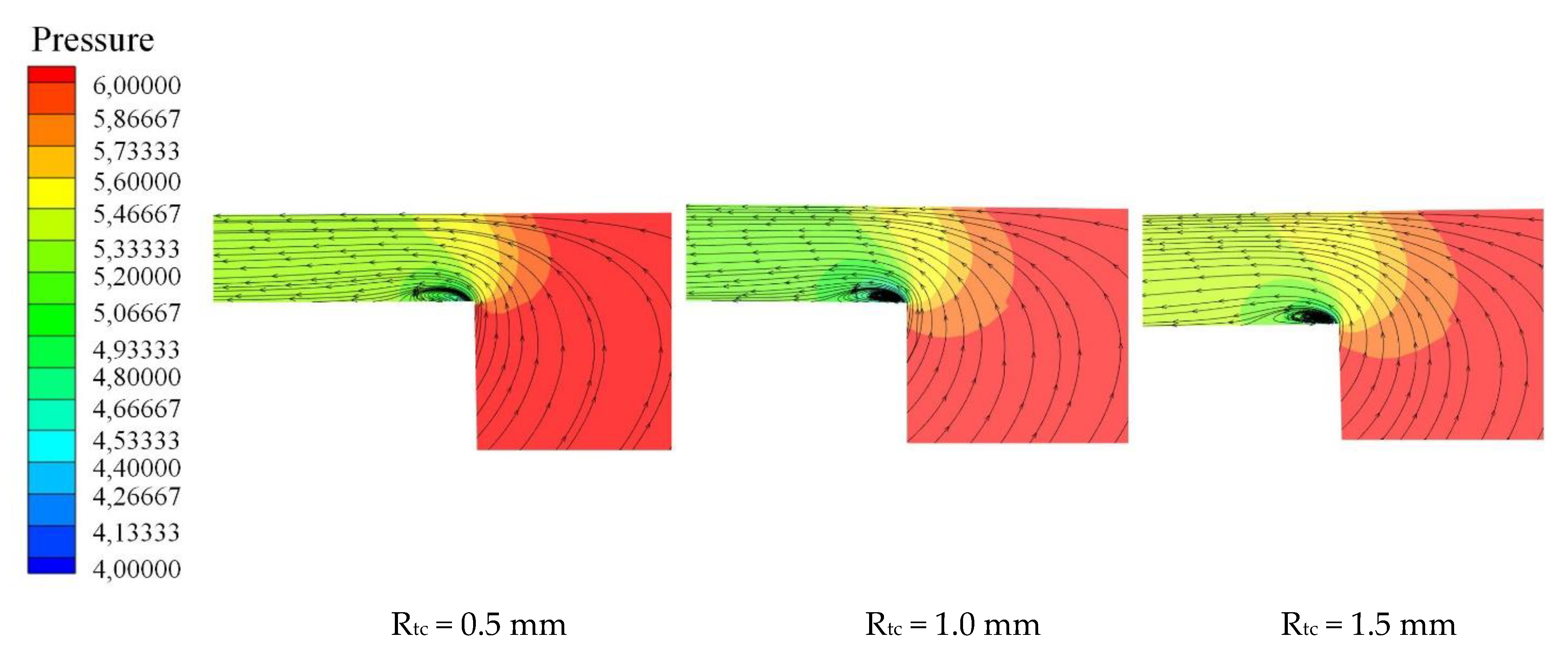
In the front part, the streamline and the pressure contours are displayed and are convenient for observing the variation regularity, as shown in Figure 15.
In Figure 15, because of the right angle near the blade tip, the flow separation phenomenon occurs when the TLF flows from the blade PS to the blade SS. Then, TSV is generated in the corner of the blade tip. After the TLF flows through the vortex, the TLF direction is consistent with the mainstream. This phenomenon indicates that the TSV scale is small and has little effect on the internal flow. The TSV is more obvious as the blade tip clearance is enlarged to 1.0 mm. In addition, as the blade tip clearance is enlarged to 1.5 mm, the jet effect fades and the TLF velocity is reduced. The TSV intensity is about the same at tip clearances of 1.0 mm and 1.5 mm. Moreover, the local low-pressure region induced by the TSV greatly increases the tip clearance cavitation possibility.
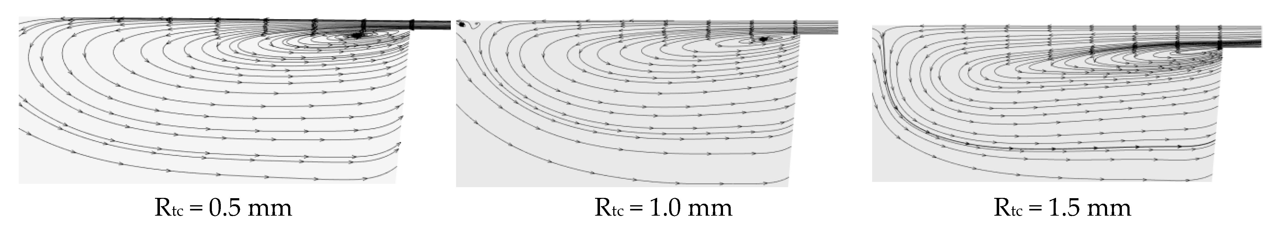
The streamlines in the latter part are displayed in Figure 16. In Figure 16, the jet-wake structure is generated as TLF flows out of the tip clearance, then the wake vortex is formed near SS. As the blade tip clearance is small, the TLF velocity is greater. Meanwhile, the influence range and the location of the wake vortex are larger and closer to the shroud, respectively. However, when the blade tip clearance rises, the wake vortex has a tendency to move from the shroud to the hub. This further deteriorates the flow characteristics in the main flow region in the impeller.
6. Conclusions
(1) With an increase in flow rate, the head of the pump without tip clearance is gradually decreased and a saddle curve appears. With growth of blade tip clearance, the helico-axial flow pump head is gradually decreased and the saddle shape disappears. When the blade tip clearance rises, the helico-axial flow-pump efficiency is gradually decreased.
(2) Tip clearance affects the pressurization performance of the helico-axial flow pump. Meanwhile, the flow state near the blade tip is also greatly affected by blade tip clearance. In addition, the TLV may cause large hydraulic loss.
(3) The TLF forms a TSV when it enters the tip clearance and forms a TLV when it leaves the blade tip clearance. The TLV is related to the blade tip clearance size. At the same time, there is low-pressure near the TSV, which also increases the possibility of cavitation. In addition, as the blade tip clearance rises, the TLV moves along the blade from the LE to the TE.
Author Contributions
Conceptualization: N.K.; software: N.K. and Z.L.; validation: Z.L. and G.S.; writing—original draft preparation: N.K., Z.L., and G.S.; writing—review and editing: N.K. and Z.L.; supervision: X.L. All authors have read and agreed to the published version of the manuscript.
Funding
This work was supported by the National Key Research and Development Program (2018YFB0905200), Open Research Fund Program of State key Laboratory of Hydroscience and Engineering (sklhse-2021-E-03), Education department key project of Sichuan province of China (Grant No. 17ZA0366), the Key scientific research fund of Xihua University of China (Grant No. Z1510417), Open Research Subject of Key Laboratory of Fluid and Power Machinery, Ministry of Education (Grant No. LTDL2020-008).
Conflicts of Interest
The authors declare no conflict of interest.
Nomenclature
| BEP | Best efficiency point |
| CFD | Computational fluid dynamics |
| FVM | Finite volume method |
| IGVFs | Inlet gas void fractions |
| LE | Leading edge |
| PIV | Particle image velocimetry |
| PS | Pressure side |
| RANS | Reynolds-averaged Navier–Stokes equations |
| RMS | Root mean square |
| SS | Suction side |
| TE | Trailing edge |
| TLF | Tip leakage flow |
| TLV | Tip leakage vortex |
| TSV | Tip separation vortex |
| Symbols | |
| r* | Radial coefficient |
References
- Kim, J.; Lee, H.; Yoon, J.; Lee, K.; Lee, Y.; Choi, Y. Multi objective optimization of a multiphase pump for offshore plants. In Proceedings of the ASME 2014 4th Joint Us-European Fluids Engineering Division Summer Meeting, Chicago, IL, USA, 3–7 August 2014; pp. 1–7. [Google Scholar]
- Kim, J.; Lee, H.; Kim, J.; Choi, Y.; Yoon, J.; Yoo, I.; Choi, W. Improvement of hydrodynamic performance of a multiphase pump using design of experiment techniques. J. Fluids Eng. 2015, 137, 1–15. [Google Scholar]
- Zhang, J.; Cai, S.; Zhu, H.; Qiang, R. Experimental study of gas-liquid two-phase flow pattern in a helico-axial multipahse pump by visualization. J. Eng. Thermophys. 2015, 36, 1937–1941. [Google Scholar]
- Zhang, J.; Cai, S.; Zhu, H. Visualization test for flow field of gas-liquid two-phase in the entrance of rotodynamic multiphase pump. J. Mech. Eng. 2015, 51, 184–190. [Google Scholar]
- Shi, G.; Liu, Z.; Xiao, Y.; Li, H.; Liu, X. Effect of the inlet gas void fraction on the tip leakage vortex in a multiphase pump. Renew. Energy 2020, 150, 46–57. [Google Scholar] [CrossRef]
- Wang, L.; Lu, J.; Liao, W.; Zhao, Y.; Wang, W. Numerical simulation of the tip leakage vortex characteristics in a semi-open centrifugal pump. Appl. Sci. 2019, 9, 5244. [Google Scholar] [CrossRef] [Green Version]
- Miorini, R.; Wu, H.; Katz, J. The internal structure of the tip leakage vortex within the rotor of an axial waterjet pump. J. Turbomach. 2012, 134, 1–14. [Google Scholar] [CrossRef]
- Ji, L.; Li, W.; Shi, W.; Chang, H.; Yang, Z. Energy characteristics of mixed-flow pump under different tip clearances based on entropy production analysis. Energy 2020, 199, 117447. [Google Scholar] [CrossRef]
- Liu, Y.; Tan, L. Tip clearance on pressure fluctuation intensity and vortex characteristic of a mixed flow pump as turbine at pump mode. Renew. Energy 2018, 129, 606–615. [Google Scholar] [CrossRef]
- Zhang, D.; Shi, L.; Chen, J.; Pan, Q.; Shi, W. Experimental analysis on characteristic of cavitation in tip region of axial flow pump impeller. J. Zhejiang Univ. (Eng. Sci.) 2016, 50, 1585–1592. [Google Scholar]
- Li, Y.; Hu, P.; Li, R.; Li, P.; Bi, Z. Numerical analysis for effects of different blade tip clearance on performance in mixed-flow pump. Trans. Chin. Soc. Agric. Eng. 2014, 30, 86–93. [Google Scholar]
- Zhang, J.; Fan, H.; Zhang, W.; Xie, Z. Energy performance and flow characteristics of a multiphase pump with different tip clearance sizes. Adv. Mech. Eng. 2019, 11, 1–14. [Google Scholar] [CrossRef]
- Zhang, D.; Shi, W.; Van Esch, B.; Shi, L.; Dubuisson, M. Numerical and experimental investigation of tip leakage vortex trajectory and dynamics in an axial flow pump. Comput. Fluids 2015, 112, 61–71. [Google Scholar] [CrossRef]
- Shi, G.; Liu, Z.; Xiao, Y.; Li, H.; Liu, X. Velocity characteristics in a multiphase pump under different tip clearances. Proc. Inst. Mech. Eng. 2021, 235, 454–475. [Google Scholar] [CrossRef]
- Shi, G.; Liu, Z.; Liu, X.; Xiao, Y.; Tang, X. Phase Distribution in the Tip Clearance of a Multiphase Pump at Multiple Operating Points and Its Effect on the Pressure Fluctuation Intensity. Processes 2021, 9, 556. [Google Scholar] [CrossRef]
- Han, W.; Liu, Y.; Gong, C.; Su, Y.; Guo, P.; Su, M.; Shi, F.; Wei, Z. Effect of tip clearance on performance of contra-rotating axial flow water-jet propulsion pump. Mod. Phys. Lett. B 2020, 34, 1–16. [Google Scholar] [CrossRef]
- Shen, S.; Qian, Z.; Ji, B.; Agarwal, R. Numerical investigation of tip flow dynamics and main flow characteristics with varying tip clearance widths for an axial-flow pump. Proc. Inst. Mech. Eng. Part A J. Power Energy 2019, 233, 1–13. [Google Scholar] [CrossRef]
- Xu, B.; Shen, X.; Zhang, D.; Zhang, W. Experimental and numerical investigation on the tip leakage vortex cavitation in an axial flow pump with different tip clearances. Processes 2019, 7, 935. [Google Scholar] [CrossRef] [Green Version]
- Ji, L.; Li, W.; Shi, W.; Agarwal, R. Transient characteristics of internal flow fields of mixed-flow pump with different tip clearances under stall condition. Proc. Inst. Mech. Eng. Part A J. Power Energy 2021, 235, 700–717. [Google Scholar] [CrossRef]
- Zhang, D.; Shen, X.; Dong, Y.; Wang, C.; Liu, A.; Shi, W. Numerical simulation of different blade tip clearances on internal flow characteristics in mixed-flow pump. J. Drain. Irrig. Mach. Eng. 2020, 38, 757–763. [Google Scholar]
- Li, W.; Ji, L.; Shi, W.; Li, E.; Yang, Z. Particle image velocimetry measurement of flow fields in a mixed-flow pump with non-uniform tip clearance. J. Vis. 2020. (prepublish). [Google Scholar] [CrossRef]
- Ji, L.; Li, W.; Shi, W.; Zhou, L.; Agarwal, R.; Sun, S. Experimental Study of Pressure Pulsation in a Mixed-Flow Pump with Different Tip Clearances Based on Wavelet Analysis. Shock. Vib. 2020. [Google Scholar] [CrossRef]
- Parikh, T.; Mansour, M.; Thévenin, D. Investigations on the effect of tip clearance gap and inducer on the transport of air-water two-phase flow by centrifugal pumps. Chem. Eng. Sci. 2020, 218. [Google Scholar] [CrossRef]
- Zhang, Q.; Yang, J.; Li, H.; Yan, S.; Li, Y. Study on the Flow Characteristics of Variable Tip Clearance for Semi-open lmpeller Centrifugal pump. Hydraul. Pneum. Seals 2021, 41, 1–6. [Google Scholar]
- Cui, B.; Huang, D.; Shi, P.; Jin, Q. Effect of tip clearance on performance of low specific speed centrifugal pump with semi-open impeller. J. Drain. Irrig. Mach. Eng. 2012, 30, 283–288. [Google Scholar]
- Hao, Y.; Tan, L. Symmetrical and unsymmetrical tip clearances on cavitation performance and radial force of a mixed flow pump as turbine at pump mode. Renew. Energy 2018, 127, 368–376. [Google Scholar] [CrossRef]
- Xu, Y.; Tan, L.; Liu, Y.; Cao, S. Pressure fluctuation and flow pattern of a mixed-flow pump with different blade tip clearances under cavitation condition. Adv. Mech. Eng. 2017, 9, 1–12. [Google Scholar] [CrossRef]
- Han, W.; Xu, D.; Guo, W.; Su, M.; Chen, Y.; Han, Y. Effects of Axial Clearance on Hydraulic Characteristics of Counter-Rotating Water-Jet Pump. J. Propuls. Technol. 2019, 40, 2144–2152. [Google Scholar]
- Ngoc Tran, B.; Jeong, H.; Kim, J.; Park, J.; Yang, C. Effects of Tip Clearance Size on Energy Performance and Pressure Fluctuation of a Tidal Propeller Turbine. Energies 2020, 13, 4055. [Google Scholar] [CrossRef]
- Zhu, W.; Wang, S.; Zhang, L.; Ding, J.; Wang, Z. Effect of tip clearance size on the performance of a low-reaction transonic axial compressor rotor. Proc. Inst. Mech. Eng. Part A J. Power Energy 2020, 234, 127–142. [Google Scholar] [CrossRef]
- Geng, M.; Song, Y.; Cheng, A.; Feng, H. Numerical Simulation of the Influence of Tip Clearance on the Performance of Centrifugal Cold Compressor. Int. J. Fluid Mach. Syst. 2020, 13, 214–221. [Google Scholar] [CrossRef]
- Suh, J.; Kim, J.; Choi, Y.; Kim, J.; Joo, W.; Lee, K. Multi-objective optimization of the hydrodynamic performance of the second stage of a multi-phase pump. Energies 2017, 10, 1334. [Google Scholar] [CrossRef] [Green Version]
Figure 1.
Computation model.

Figure 2.
Helico-axial flow pump test rig.

Figure 3.
y+ of the impeller and diffuser.

Figure 4.
Computational domain mesh.

Figure 5.
CFD and experimental flow fields.

Figure 6.
Hydraulic performance.

Figure 7.
Pressure on blade surface. (a) pressure on PS; (b) pressure on SS.

Figure 8.
Radial coefficient and flow coefficient in impeller.

Figure 9.
Impeller pressurization performance. (a) Radial pressurization performance from impeller inlet to middle (b) Radial pressurization performance from impeller middle to outlet.
Figure 9.
Impeller pressurization performance. (a) Radial pressurization performance from impeller inlet to middle (b) Radial pressurization performance from impeller middle to outlet.

Figure 10.
Pressure on the radial coefficient r* = 0.9.

Figure 11.
Velocity at the radial coefficient r* = 0.9.

Figure 12.
Streamlines at the radial coefficient r* = 0.9.

Figure 13.
Turbulent kinetic energy on the impeller and diffuser meridional plane.

Figure 14.
Observation region.

Figure 15.
Streamlines and pressure contours on front part.

Figure 16.
Streamlines on latter part.


Table 1.
Main parameters of helico-axial flow pump.
| Parameters | Value |
|---|---|
| Design flow rate Q/m3/h | 100 |
| Design rotational speed n/rpm | 3000 |
| Impeller blades Z1 (-) | 3 |
| Diffuser blades Z2 (-) | 7 |
Table 2.
Main equipment.
| Number | Equipment | Value | Precision |
|---|---|---|---|
| 1 | High-speed photography (RDT16-4G) | 500 fps, 1280 × 1024 pixels | (-) |
| 2 | Pressure gauge | 0–5 Mpa | 0.25% |
| 3 | Flow meter | 14–200 m3/h | 0.5% |
| 4 | Air compressor | 200 m3/h | (-) |
| 5 | Flow control valve | DN = 100 mm | (-) |
Table 3.
Mesh distribution.
| Parameters | Inlet Pipe | Impeller | Diffuser | Outlet Pipe | Total |
|---|---|---|---|---|---|
| Mesh 1 | 182,476 | 1,001,925 | 443,534 | 642,488 | 2,270,423 |
| Mesh 2 | 182,476 | 1,736,925 | 750,596 | 642,488 | 3,312,485 |
| Mesh 3 | 182,476 | 2,686,650 | 1,146,663 | 642,488 | 4,658,277 |
| Mesh 4 | 182,476 | 3,234,534 | 1,361,612 | 642,488 | 5,421,110 |
| Mesh 5 | 182,476 | 4,618,575 | 1,689,240 | 642,488 | 7,132,779 |
Table 4.
Mesh independence verification.
| Parameters | Mesh 1 | Mesh 2 | Mesh 3 | Mesh 4 | Mesh 5 |
|---|---|---|---|---|---|
| Head | 8.2623 | 8.2620 | 8.3326 | 8.3242 | 8.3991 |
| Efficiency | 42.40% | 42.59% | 42.83% | 42.94% | 42.97% |
| Head/Head1 | 1 | 0.9999 | 1.0085 | 1.0074 | 1.0165 |
| Efficiency/Efficiency1 | 1 | 1.0043 | 1.0100 | 1.0127 | 1.0134 |
Table 5.
Fluid properties.
| Properties | Density | Dynamic Viscosity | Molar Mass |
|---|---|---|---|
| Water | 997 kg/m3 | 9.028 × 10⁻⁴ Pa·s | 18.02 kg/mol |
Publisher’s Note: MDPI stays neutral with regard to jurisdictional claims in published maps and institutional affiliations. |
© 2021 by the authors. Licensee MDPI, Basel, Switzerland. This article is an open access article distributed under the terms and conditions of the Creative Commons Attribution (CC BY) license (https://creativecommons.org/licenses/by/4.0/).
Share and Cite
MDPI and ACS Style
Kan, N.; Liu, Z.; Shi, G.; Liu, X. Effect of Tip Clearance on Helico-Axial Flow Pump Performance at Off-Design Case. Processes 2021, 9, 1653. https://0-doi-org.brum.beds.ac.uk/10.3390/pr9091653
AMA Style
Kan N, Liu Z, Shi G, Liu X. Effect of Tip Clearance on Helico-Axial Flow Pump Performance at Off-Design Case. Processes. 2021; 9(9):1653. https://0-doi-org.brum.beds.ac.uk/10.3390/pr9091653
Chicago/Turabian StyleKan, Nengqi, Zongku Liu, Guangtai Shi, and Xiaobing Liu. 2021. "Effect of Tip Clearance on Helico-Axial Flow Pump Performance at Off-Design Case" Processes 9, no. 9: 1653. https://0-doi-org.brum.beds.ac.uk/10.3390/pr9091653
Note that from the first issue of 2016, this journal uses article numbers instead of page numbers. See further details here.