Isolated Power System Safety Analysis †

Department of Automation and Electrical Engineering, “Dunarea de Jos” University of Galati, 80008 Galați, Romania
†
Presented at the 14th International Conference on Interdisciplinarity in Engineering—INTER-ENG 2020, Târgu Mureș, Romania, 8–9 October 2020.
Proceedings 2020, 63(1), 21; https://0-doi-org.brum.beds.ac.uk/10.3390/proceedings2020063021
Published: 14 December 2020
(This article belongs to the Proceedings of The 14th International Conference on Interdisciplinarity in Engineering—INTER-ENG 2020)
Abstract
:For a specific vessel, the safety of the isolated power system is analyzed. Concerning the safety, the choice of propulsion system and the classification regulations have a major role for the power system design. The rules of SOLAS (International Convention for the Safety of Life at Sea), the flag state, and the harbor authorities are pointing to the basic level of safety, while the classification societies are pointing to the basic navigational regulations. A case study of the main switchboard and emergency switchboard safety, while taking into account different short circuits for the specific operational configuration of the electrical network, makes a comparative study possible.
1. Introduction
Electric installations design of the ships is a very complete part of electrical engineering. Their safety is one of the main concerns of the specialists, as they are isolated power systems and they have to cover the complete spectrum from power generation to distribution and switchgear to all consumers [1,2]. The protections, the automations, the communication, and the nautical/navigation systems have to be included in the design. The electrical power for ships comes mainly from the synchronous generators [3,4]. The most common prime mover for an electric generator is often the diesel engine. Other smaller engines can be installed on a common base generator frame, but for diesel-electric important applications, it is possible that both have their own base frame and are connected with a flexible coupling [5,6]. For safety reasons an emergency diesel generator (EG) is always used to give main electrical power if the main source is in failure/blackout [7]. The emergency generator/source must be self-contained and built independent of the main engine room systems. It is completed with its own independent systems for starting, fuel oil, lubrication oil, cooling, and preheating, for an independent working purpose. The consumers supplied by the EG, as the regulations require, are the main consumers like: emergency lighting, navigation/communication devices, steering gear, fire and sprinkler pumps, bilge pump, water tight doors, and lifts.
When the emergency source of electrical network is an electric generator, it has to be provided with a transitional emergency electrical power source. The ship uses the selected uninterruptible power supply (UPS) application. A battery or an uninterruptible power supply must be used as a standby power supply with a capacity of 30 min. Navigation and safety aspects, required by the ship class, point to the use of the UPS, such as: automation system, navigation system, radio/safety announcement equipment, emergency lighting, watertight doors, etc.
2. Structure of the Electrical Network
Taking into account the isolated configuration nature of electrical power system onboard ship, several means are used to assure its safety and continuous availability. The main switchboard is divided into two or more sections power supplied by the main diesel generators (DG) [8,9]. The switchboard supplied by an emergency generator as well as the uninterrupted (battery secured) power supply as Figure 1 shows is very important, both for reasons of safety and to ensure fault tolerant, redundant configuration. The EG must also be able to start automatically if the main source of electrical power fails to supply the emergency switchboard. In this case, the EG is automatically started and connected to the emergency switchboard by its automation power management system [9,10].
In addition to auxiliary generators an electrical network often has shaft generators (SG) driven by the main engine. Sometimes shaft generators are used only for driving the thrusters during maneuvers, while in other applications they are able also to supply the ship’s network. For this reason, some interconnections are required to avoid overload or damage to the network. The following feeder combinations, for example, are prohibited [5,10]:
- If the bus-tie breaker is closed, the SG breakers are interlocked in the open position;
- If the SG breaker is closed, the bus-tie breaker is interlocked in the open position;
- If the bow thruster breaker is closed, the SG breaker is interlocked in the open position;
- When synchronizing the SG in parallel with the diesel generator (DG), the DG breaker has to be open with a time delay;
- Interlocking every auxiliary power station (switchboard) must be defined separately.
When the SG is connected and is supplying the ship electrical installation, a constant speed mode for the main engine has to be chosen, meaning the network frequency. In constant speed mode, the propulsion will be controlled with the help of the pitch adjustments, using the controllable pitch propeller (CPP). The main engine can drive the SG when this is disconnected from the main propulsion line. In this case, the main engine runs as an auxiliary engine, for example to supply the big consumers in special regime like loading or unloading in the harbor.
First, the propulsion type has to be chosen, diesel-mechanic or diesel-electric, then other decisions are made, like the following [10,11]:
- Evaluation of the maximum electrical power needed to be generated (the load reservation is agreed with the customer);
- Given that information on the electrical loads/consumers, which can be based on relative values calculated from reference ships, taking into account different ship operating modes like: sailing, maneuvering, loading, harbor, dynamic positioning-DP this will affect the total load computing;
- Finding the generator number and its apparent power S [VA];
- Selection of main voltage and frequency;
- Computing the voltage drop;
- Computing of the short circuit regime and finding the network selectivity.
3. Designing the Electrical Network According to the Safety Rules
In the design stage, the first step is to define the ship type. The ship type, size, and purpose are key factors when dimensioning the electrical network. The following are expressing the different electrical needs of different types of ship [4]:
- For cargo ships, the handling equipment has the main role in containerships, and gives the requirement characteristics of the power electrical network;
- For tankers, the pumps and the compressors are mainly the significant factors;
- For passenger ships, the electrical consumers are mainly the air conditioning, the galley equipment, lighting installation, and the transverse thrusters for maneuvering in the harbor;
- For the ships with electric propulsion, the propulsion machinery itself is the dominating factor.
The choice of propulsion system and the classification regulations have an impact on the design of the power electrical network. The rules of SOLAS (International Convention for the Safety of Life at Sea), the flag state, and the harbor authorities specify the basic level of safety, while the classification societies specify the basic navigational regulations, like a redundant propulsion, an unmanned engine room, and a green power system.
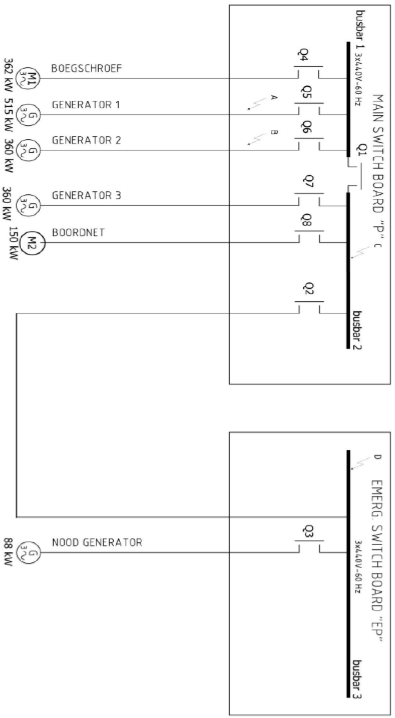
For the study case configuration of the power system in Figure 2, the generators were already selected, and the short circuit safety analysis is presented, taking into account the functional alternatives:
Case 1—Generator 1 is in running mode, the rest of the generators are stopped. Generator 1 is supplying the thruster engine and the electrical system. Q1 is closed, Q2 and Q3 opened.
Case 2—Generators 2 and 3 are in running mode, the rest of the generators are stopped. Generators 2 and 3 are supplying the thruster engine and the electrical system. Q1 is closed, Q2 and Q3 opened.
Case 3—Generator 3 is in running mode, the rest of the generators are stopped. Generator 3 is supplying the electrical system. Q1, Q2, and Q3 are opened.
Case 4—Generator 2 is in running mode, the rest of the generators are stopped. Generator 3 is supplying the electrical system. Q1 is closed, Q2 and Q3 are opened.
Case 5—Emergency generator (EG) is in running mode, the rest of the generators are stopped. EG is supplying only the essential consumers from the electrical system, but not the thruster. Q1 is opened, Q2 and Q3 are closed.
The short circuit computation, with the help of the Germanischer Lloyd, Short Circuit Calculation Program and using its design safety rules [12,13], takes into account the short circuit locations A, B, C, and D. The calculation obtained the short circuit current values for the a.c. three phase system based on IEC 61363 standard. The short circuit current comprises three components, a.c component (Iac), d.c. component (Idc), and the peak current (Ip). The results of the short circuit currents (in Ampere), for the location C on the main switchboard, are presented in Table 1.
These results give the overview of the needed information concerning the system safety and point to the protection equipment selection used to achieve the system safety goal. For comparison, of the system safety in all 4 analyzed cases, the peak current Iptot is used, which has the biggest computed value in the case 4. This is a result of adding the generators’ total current and the engines/motors total current, taking into account the equivalent reactance Xd’’, the nominal generator current Ign, the nominal motor current Imn, and the multiplication factors 6 for the motors case and 2.3 for the Iptot computing.
As Table 1 shows, the most dangerous case, from short circuit safety point of view, is case 4. Because case 4 is detected as the heaviest situation the system can deal with in the circuits design and equipment selection, the numerical results from case 4 will be used in design and equipment sizing. In Table 2 the nominal data computed for the electric circuits connected to the main switchboard, generator 1, generator 2, generator 3, emergency generator, and equivalent engine are presented. Table 2 also gives the selected circuit breakers data needed to achieve the operational security of the analyzed system for all the above-mentioned circuits.
4. Conclusions
This paper presents a study case analysis of the operational safety for an isolated power system, in the situation of a vessel. Because the safety of the power system is the most important goal, especially for the ship’s electrical network, it is important to identify the design steps which can give the most suitable design architecture for the circuits. The marine special rules, which are mandatory, give more pressure when it comes to proposing the optimal design for the ship power system from a safety point of view. The main contribution of the paper is the proposed algorithm finding the most dangerous study case, from a short circuit safety point of view. The novelty is the procedure to select the study cases configuration which are subject for analysis by the Germanischer Lloyd, Short Circuit Calculation Program. The interpretation of the results and the conclusions of safety analysis are also a subject of the research proposed methodology. The alternatives analyzed in the paper for the operational power system specific situations help the specialist to find the most dangerous operational situation and the safest alternative possible. This gives the best confidence in the system response in case of the most dangerous short circuit possible, which can appear in the ship power electric network.
Conflicts of Interest
The author declares no conflict of interest.
References
- Borstlap, R.; Ten Katen, H. Ships’ Electrical Systems; Dokmar Maritime Publishers: Enkhuizen, The Netherlands, 2011. [Google Scholar]
- Van Dokkum, K. Ship Knowledge: A Modern Encyclopedia, 1st ed.; Dokmar Maritime Publishers: Enkhuizen, The Netherlands, 2003. [Google Scholar]
- Van Dokkum, K. Ship Knowledge: Types of Ships and Their Trades; Dokmar Maritime Publishers: Enkhuizen, The Netherlands, 2003. [Google Scholar]
- Chalfant, J. Early-stage design for electric ship. Proc. IEEE 2015, 103, 2252–2266. [Google Scholar] [CrossRef]
- Dennis, T. Practical Marine Electrical Knowledge, 3rd ed.; Witherby-Seamanship International: Edinburgh, Scotland, UK, 2014. [Google Scholar]
- Carlton, J. Marine Propellers and Propulsion; Elsevier: Amsterdam, The Netherlands, 2011. [Google Scholar]
- SOLAS. Consolidated Text of the International Convention for the Safety of the Life at Sea; International Maritime Organization: London, UK, 2014. [Google Scholar]
- Ferrante, M.; Chalfant, J.; Chryssostomidis, C.; Langland, G.; Dougal, R. Adding simulation capability to early-stage ship design. In Proceedings of the 2015 IEEE Electric Ship Technologies Symposium (ESTS), Alexandria, VA, USA, 21–24 June 2015; pp. 207–212. [Google Scholar]
- Valkeejärvi, K. The ship’s electrical network, engine control and automation. Koninklijke Gallois Genootschap Magazine, March/May 2006. [Google Scholar]
- Menis, R.; da Rin, A.; Sulligoi, G.; Vicenzutti, A. All electric ships dependable design: Implications on project management. In Proceedings of the 2014 AEIT Annual Conference—From Research to Industry: The Need for a More Effective Technology Transfer (AEIT), Trieste, Italy, 18–19 September 2014; pp. 1–6. [Google Scholar]
- Maggioncalda, M.; Gualeni, P.; Notaro, C.; Cau, C.; Bonazountas, M.; Stamatis, S. Life Cycle Performance Assessment (LCPA) Tools: Volume 1: Optimisation of Ship Design and Operation for Life Cycle; Springer: Cham, Switzerland, 2019. [Google Scholar]
- International Electro Technical Commission. Publication 60909-0 Short-circuit Current in Three Phase A.C. Systems, Part: Calculation of Systems. 2016. Available online: https://www.sis.se/api/document/preview/8018642/ (accessed on 1 January 2016).
- Germanischer Lloyd. Short Circuit Calculation Program Version GL ES 1 98. Available online: https://en.wikipedia.org/wiki/Germanischer_Lloyd (accessed on 4 November 2020).
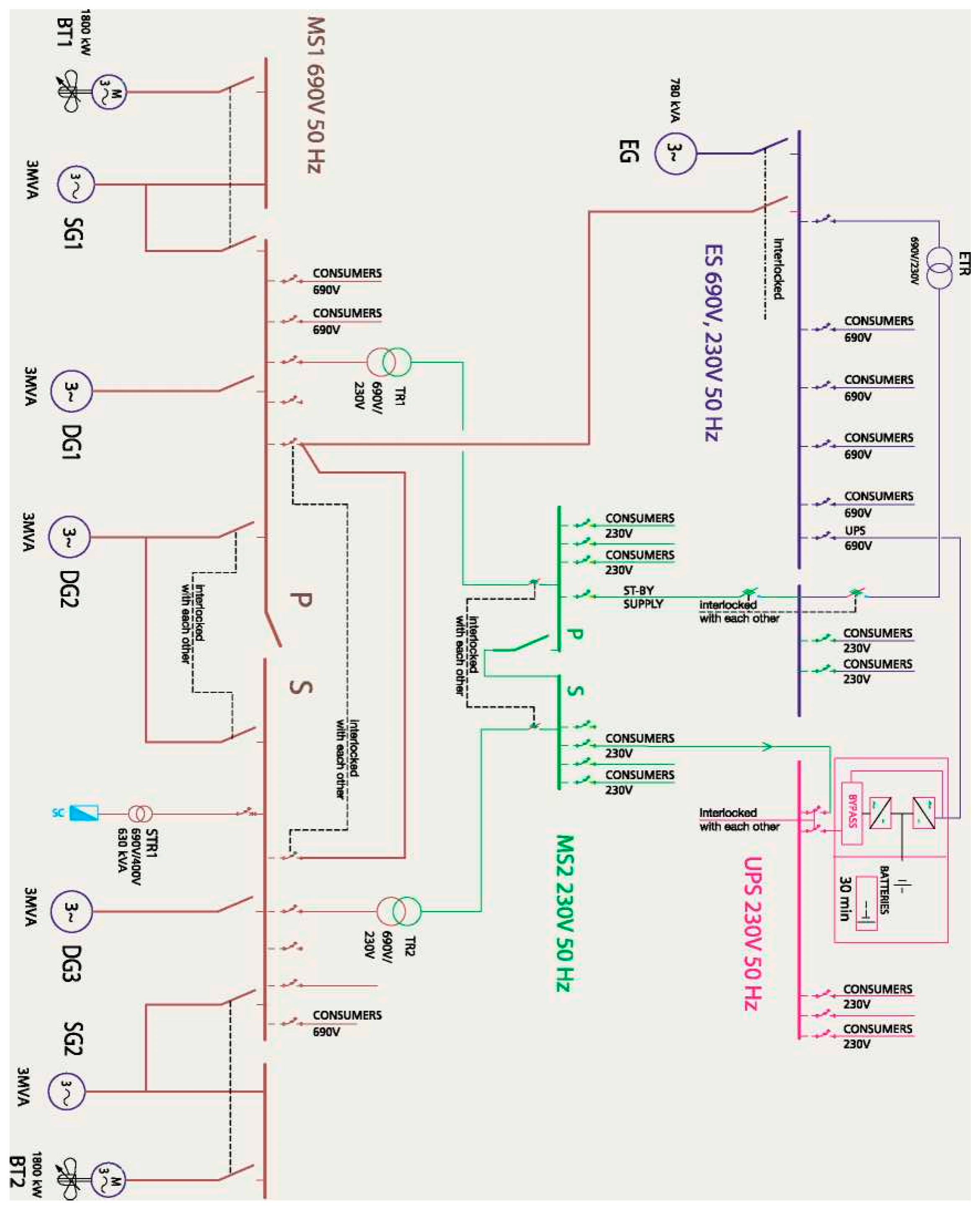
Figure 1.
Low-voltage 690V electric network for an isolated power system, for a vessel with diesel-mechanical propulsion [10].
Figure 1.
Low-voltage 690V electric network for an isolated power system, for a vessel with diesel-mechanical propulsion [10].

Figure 2.
Configuration of the main switchboard and emergency switchboard for the power system study case.
Figure 2.
Configuration of the main switchboard and emergency switchboard for the power system study case.


Table 1.
Alternatives comparation for the main switchboard (C point) short circuit computing, taking into account the functional variants in cases 1, 2, 3, and 4.
Table 1.
Alternatives comparation for the main switchboard (C point) short circuit computing, taking into account the functional variants in cases 1, 2, 3, and 4.
| SC in point C | P (kW) | I”kg | Ing | Xd’’ | Í”km | Imn | I”kgtot | I”kmtot | I”ktot | Iptot |
| Case 1 Q1 open Q2 open | 360 | 5681.09 | 624.92 | 0.11 | 1642.14 | 273.69 | 5681.09 | 1642.14 | 7323.23 | 16,843.43 |
| Case 2 Q1 open Q2 close | 360 | 5681.09 | 624.92 | 0.11 | 1642.14 | 273.69 | 6995.75 | 1642.14 | 8637.89 | 19,867.16 |
| 88 | 1314.66 | 157.76 | 0.12 | |||||||
| Case 3 Q1 close Q2 open | 360 | 5681.09 | 624.92 | 0.11 | 1642.14 | 273.69 | 21,212.07 | 5091.12 | 26,303.19 | 60,497.34 |
| 360 | 5681.09 | 624.92 | 0.11 | 3449.98 | 574.83 | |||||
| 515 | 9849.88 | 886.49 | 0.09 | |||||||
| Case 4 Q1 close Q2 close | 360 | 5681.09 | 624.92 | 0.11 | 1642.14 | 273.69 | 22,526.77 | 5091.12 | 27,617.86 | 63,521.07 |
| 360 | 5681.09 | 624.92 | 0.11 | 3449.98 | 574.83 | |||||
| 515 | 9849.88 | 886.49 | 0.09 | |||||||
| 88 | 1314.66 | 157.76 | 0.12 |
Table 2.
Electric circuits nominal data and circuit breakers selection for the heaviest operational state, represented by the case 4.
Table 2.
Electric circuits nominal data and circuit breakers selection for the heaviest operational state, represented by the case 4.
| P (kW) | In (A) | Ku | Is (A) | Kss | Iss (A) | |
| Generator 1 | 515 | 886.49 | 0.9 | 797.84 | 1.12 | 900.76 |
| Generator 2 | 360 | 624.92 | 0.9 | 562.42 | 1.1 | 618.67 |
| Generator 3 | 360 | 624.92 | 0.9 | 562.42 | 1.1 | 618.67 |
| Generator emergency | 88 | 157.76 | 0.9 | 141.98 | 1.1 | 156.18 |
| Thruster engine | 362 | 574.83 | 0.9 | 517.34 | 1.1 | 569.08 |
| Equivalent | 150 | 273.79 | 0.9 | 246.32 | 1.1 | 270.95 |
| Equipment | In (A) | Ir (A) | Irt (A) | tr (s) | Iinst (A) | |
| Masterpact NT10H1/Micrologic 7.0A | 1000 | 900 | - | 24 | off | |
| Compact NSX 630 N/ Micrologic 6.30A | 630 | 630 | 618 | 0.5 | 945 | |
| Compact NSX 630 N/ Micrologic 6.30A | 630 | 618 | 618 | 0.5 | 945 | |
| Compact NSX 160 N/ Micrologic 6.20A | 160 | 160 | 156 | 0.5 | 240 | |
| Compact NSX 630 N/ Micrologic 6.30A | 630 | 570 | 569 | 0.5 | 945 | |
| Compact NSX 400 N/ Micrologic 6.3 E-M | 320 | 280 | 270 | 5 | 4800 | |
Publisher’s Note: MDPI stays neutral with regard to jurisdictional claims in published maps and institutional affiliations. |
© 2020 by the author. Licensee MDPI, Basel, Switzerland. This article is an open access article distributed under the terms and conditions of the Creative Commons Attribution (CC BY) license (http://creativecommons.org/licenses/by/4.0/).
Share and Cite
MDPI and ACS Style
Dumitrescu, M. Isolated Power System Safety Analysis. Proceedings 2020, 63, 21. https://0-doi-org.brum.beds.ac.uk/10.3390/proceedings2020063021
AMA Style
Dumitrescu M. Isolated Power System Safety Analysis. Proceedings. 2020; 63(1):21. https://0-doi-org.brum.beds.ac.uk/10.3390/proceedings2020063021
Chicago/Turabian StyleDumitrescu, Mariana. 2020. "Isolated Power System Safety Analysis" Proceedings 63, no. 1: 21. https://0-doi-org.brum.beds.ac.uk/10.3390/proceedings2020063021