1. Introduction
Sports injuries are common, and place substantial burdens on individuals and national economies (estimated at ~
$0.5 Billion a year in The Netherlands [
1]), with high treatment costs for common injuries [
2]. Preventing, or reducing the severity of injuries with protective equipment (personal protective equipment (PPE) i.e., knee pads and environmental i.e., crash mats) is more cost effective than medical treatment [
3]. PPE and crash mats typically contain compliant material (i.e., foam) to cushion impacting bodies. A stiff shell in PPE can spread concentrated loads [
4,
5].
Standards for certifying protective equipment must be repeatable and cost effective, defining test conditions and pass criteria (i.e., drop rig specifications, impact energy and minimum peak force in BS 6183-3:2000 [
6]). Simplifications mean tests do not always reflect the sporting conditions/incidences where protection is required [
1,
3,
7]. Certification (i.e., pass/fail) is typically the only information that users have detailing equipment function. If tests are not appropriate, equipment limitations are unclear and differences between equipment limitations and user expectations can occur, affecting risk perception and potentially putting people in danger [
2]. An example of the effect misunderstanding limitations can have is in snow-sports helmets, where standards (EN1077 [
8] and ASTMF2040 [
9]) test for linear but not rotational acceleration (which is thought to significantly increase the risk of concussion) [
10]. Helmet use in snow-sports has increased dramatically over the past twenty years due to greater awareness of the long term effects of head injury [
11], but head injury rates have not notably decreased [
11,
12]. Updating tests and protective equipment to ensure they align with user expectations could reduce the risk of injuries.
Sporting PPE is a healthy, growing market that can respond to evidence from the scientific community, seen in the previous example (where the increase in helmet sales comes from increased awareness of head injury) [
11]. Design and innovation can also increase market share for manufacturers. Innovations include non-Newtonian fluids for PPE (which can pass certification tests without a stiff shell [
13]) and slip plane technology in helmets [
14], intended to decrease rotational acceleration and concussion risk. The case for improving protection through product and material innovation is ethically and financially viable and justified, publically (to reduce costs and burdens) and commercially (to increase market share and prepare for possible changes in standards).
Auxetic materials have a negative Poisson’s ratio (NPR) [
15], which could reduce peak forces/accelerations under impacts, giving potential to improve protective equipment [
16,
17]. From elasticity theory [
18], Poisson’s ratio (
ν) influences the relationship between Young’s modulus (
E), shear modulus (
G) and bulk modulus (
K) (Equations (1) and (2)). Indentation resistance (
H, Equation (3) [
18]) is a function of
E,
ν and
x (related to indenter shape). The elastic limits for Poisson’s ratio in an isotropic material [−1 ≤
ν ≤ 0.5] mean maximum shear modulus and indentation resistance and minimum bulk modulus are achieved with an NPR (of −1).
Increasing indentation resistance could increase the operating range of protective equipment, limiting the effect of concentrated loads and reducing the chance of injuries. Lower bulk modulus increases volumetric deformation [
18], increasing energy absorption under uniaxial compression [
16,
17]. The effects of higher shear modulus and densification due to lateral material flow under an indentation have not been tested in NPR foams.
Auxetic foams were the first man-made NPR material [
19] and they are often used in studies involving impact or indentation testing [
16,
20,
21,
22], partially due to their relatively low cost and ease of fabrication. Thermoplastic auxetic foams were originally (and typically still are) fabricated with a thermo-mechanical process. Isotropic, tri-axial compression of open cell polyurethane (PU) foam buckles cell ribs in all three axes to create a re-entrant cell structure [
23]. Thermal treatment (heating and cooling) locks in the imposed re-entrant structure.
The volumetric compression ratios (VCR = Final/Initial Volume) applied during fabrication (typically 0.2 to 0.5 [
24]) are considered to have the largest effect on mechanical properties [
25], but thermal conditions are also critical. Applying compression and heating within windows of temperature and time (conversion windows) produces NPR samples. Heating below a temperature threshold (i.e., under-heating) produces unstable samples that return towards their original dimensions when released from the mould [
26]. Over-heating samples can change the base polymer or cause adhesion of cell ribs, leading to a positive Poisson’s ratio [
27]. An over-heated sample has been fabricated, with a positive Poisson’s ratio, the same density and a higher modulus than a typical NPR sample [
28].
To fabricate stable samples while reducing adhesion of cell ribs, a multi-stage approach has been used; whereby samples are removed from the oven and mould and stretched halfway through heating [
29]. An annealing stage has also been introduced, below a foams softening temperature (with stretching beforehand) [
28]. Softening temperature is used to describe a desired conversion temperature [
30], although to the best of the authors’ knowledge it has not been experimentally linked to an optimised conversion with the largest magnitude NPR. Furthermore, different foams have been used between studies so conversion conditions cannot always be transferred or compared. There is also uncertainty in how long samples should be removed from the mould and oven, and how much to stretch them by hand, between heating stages. The conditions to produce NPR or over-heated, compressed, positive Poisson’s ratio foam are (therefore) difficult to interpret.
Comparative tests between auxetic foam and its unconverted parent material begin to relate NPR to increased indentation resistance [
28] and/or lower peak acceleration or force under impacts [
20] often adapted from sporting standards [
21,
22]. Comparative open cell foams are anisotropic (cells have an elongated rise direction) [
19,
20,
23,
28] and non-linear (cells ribs buckle and stiffness reduces considerably at ~5 to ~10% compression) [
23]. The thermo-mechanical process increases density (by a factor of 2 to 5, depending on VCR), produces samples with a quasi-linear compressive stress/strain relationship [
21,
22] and can reduce or remove ‘cell rise’ and anisotropy [
19,
23].
Not all studies compare converted to unconverted foam. Commercially available ‘felted’ foams (Basotect, BASF & Pinta 9700, Pinta Foamtec) with comparative density to typical auxetic foams have been compared to thermo-mechanically fabricated auxetic foams [
20]. ‘Felted’ foams were anisotropic and marginally auxetic. PU foam with an NPR in one direction and comparable density and compressive stress/strain relationship to the foam it was fabricated from [
31] could be a useful comparison, but both foams are anisotropic and so comparison with Equation (3) would be invalid.
A comparison has been made between over-heated, tri-axially compressed foam with a positive Poisson’s ratio and NPR foam converted within the required time & temperature windows. Density was comparable, but NPR foam had lower compressive modulus [
28]. The NPR foam required more force to compress with an indenter than the over-heated sample (when normalised to compressive modulus). Indenter shape (
x, Equation (3)) was not included in the normalisation and changes to linearity and isotropy were not clarified. There is, therefore, scope to experimentally confirm indentation theory (Equation (3)) in NPR foams.
2. Materials and Methods
Samples of PU foam (Articoli Resine Espanse, Italy, PU R40, 28 kg/m
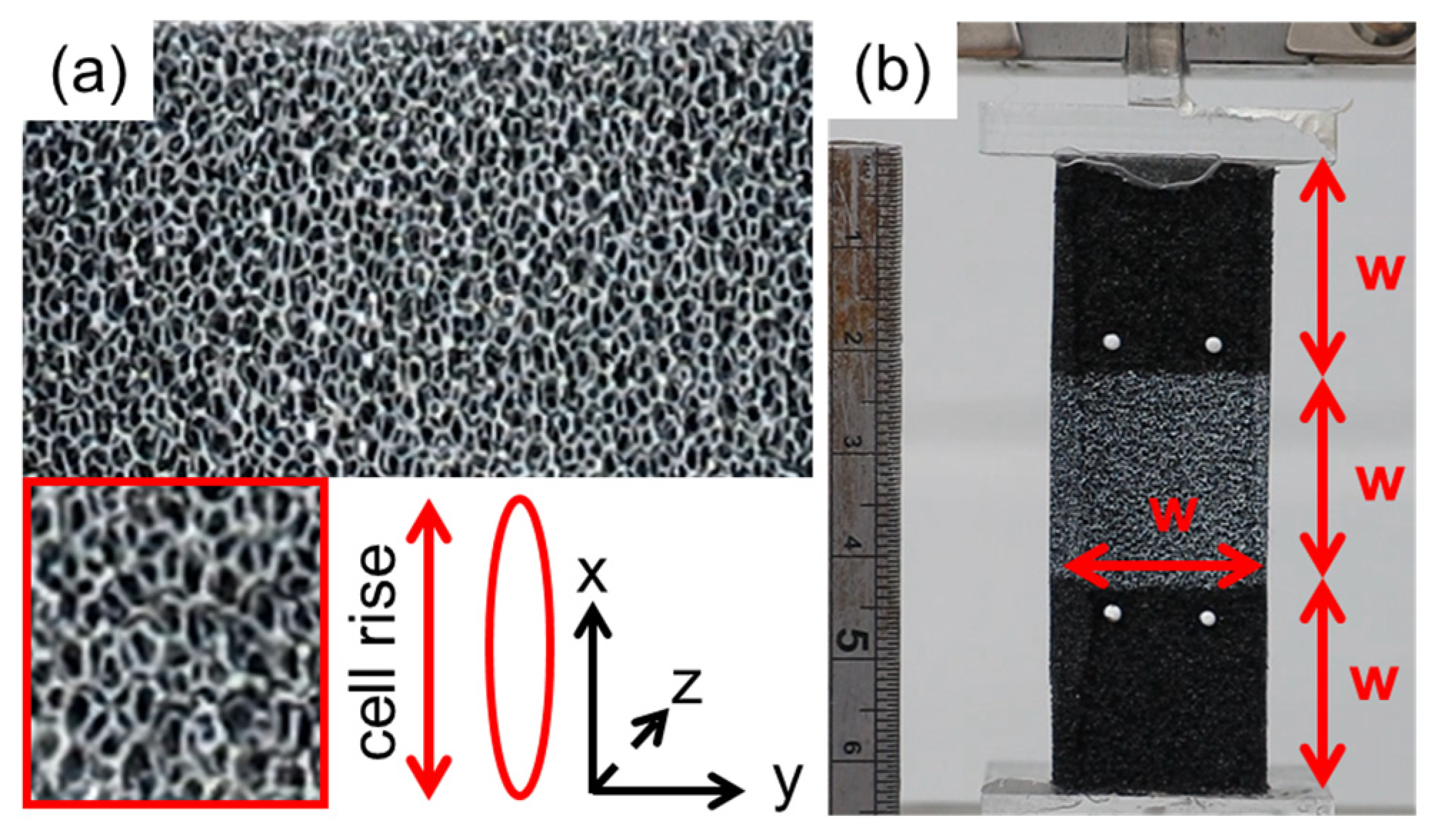
3, 32 × 32 × 143 mm, cut with a hot wire) were thermo-mechanically converted. Foam was tri-axially compressed to a VCR of 0.34, and then heat treated in an oven (FALC Instruments STF-N 52Lt, Treviglio, Italy)) between 120 and 180 °C, at increments of 10 °C for 20 min conversions and 20 °C for 60 min conversions. Three samples were fabricated for each condition and cooled to room temperature in air, in their moulds (30 to 60 min). Foam cell rise direction was either parallel or perpendicular to the longest sample dimension (
Figure 1a). Sample dimensions were taken using Vernier callipers prior to mechanical testing to determine uptake of imposed dimensions after ~20 h.
All samples were characterised quasi-statically using an Instron 3367 with a 500 N load cell. Samples were cut (using a Stanley knife) to dimensions carefully selected to reduce end effects while limiting buckling during compression, with total length being triple the sample width (
Figure 1b). Cyclic testing to 10% compression followed by 10% tension (strain rate 0.0083 s
−1) allowed both compressive and tensile Poisson’s ratio measurements. Tests were run for five cycles each, with the fifth cycle analysed [
32].
Digital Image Correlation (DIC) was used to obtain axial and lateral strains (but checked against marker tracking [
33] as used in previous studies [
16,
22]). The speckled area was placed in the centre of each sample in a square (sides ~ equal to sample width). Tests were filmed using a video camera (Cannon Powershot G15, 1080p, 60 fps), with analysis carried out in commercial software (GOM Correlate). Linear trend lines fitted to plots of axial vs transverse strain (mean value across all facets within target area, over the entire strain range up to 10%) were used to obtain Poisson’s ratio. Stresses were calculated from cross sectional areas (using a Vernier Calliper) and force data from the Intron’s built in software (Bluehill 4.0). Tensile and compressive Young’s modulus were calculated from the initial linear region (selected through visual inspection) of stress/strain plots, with strain from DIC.
3. Results
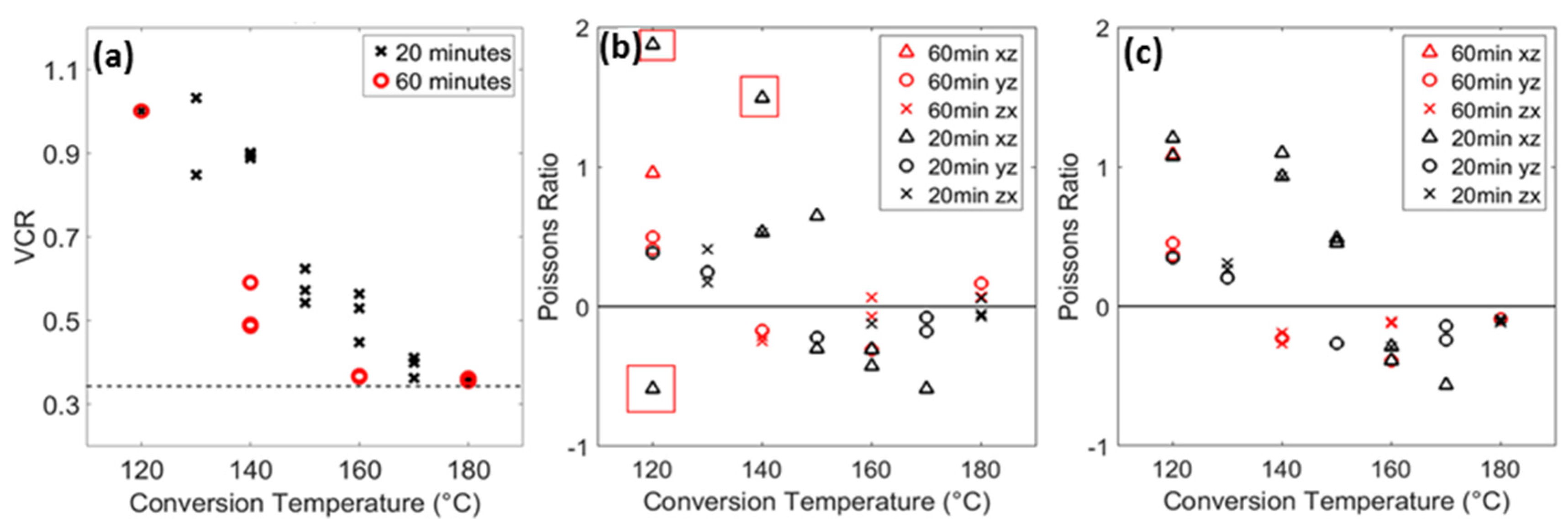
Uptake of imposed VCR increased with conversion temperature and time (
Figure 2a). Samples converted at lower times and temperatures did not hold their imposed compression, hereafter referred to as ‘unconverted’. Samples converted at or above 160 °C for 60 min, and 170 °C or more for 20 min retained compression (after ~20 h). The highest magnitudes of NPR (~−0.3) were comparable in compression and tension (
Figure 2b,c respectively). Tensile Poisson’s ratio was negative (in all samples) after 20 min of heating between 160 and 180 °C and 60 min of heating between 140 and 180 °C (
Figure 2c), compressive NPR was achieved in fewer conditions (160 to 170 °C for 20 min and 140 °C for 60 min). Poisson’s ratios were above 0.5 in certain orientations of anisotropic unconverted samples (
Figure 2b) that had not retained imposed compression (
Figure 2a). Three outliers were noticed under compression (
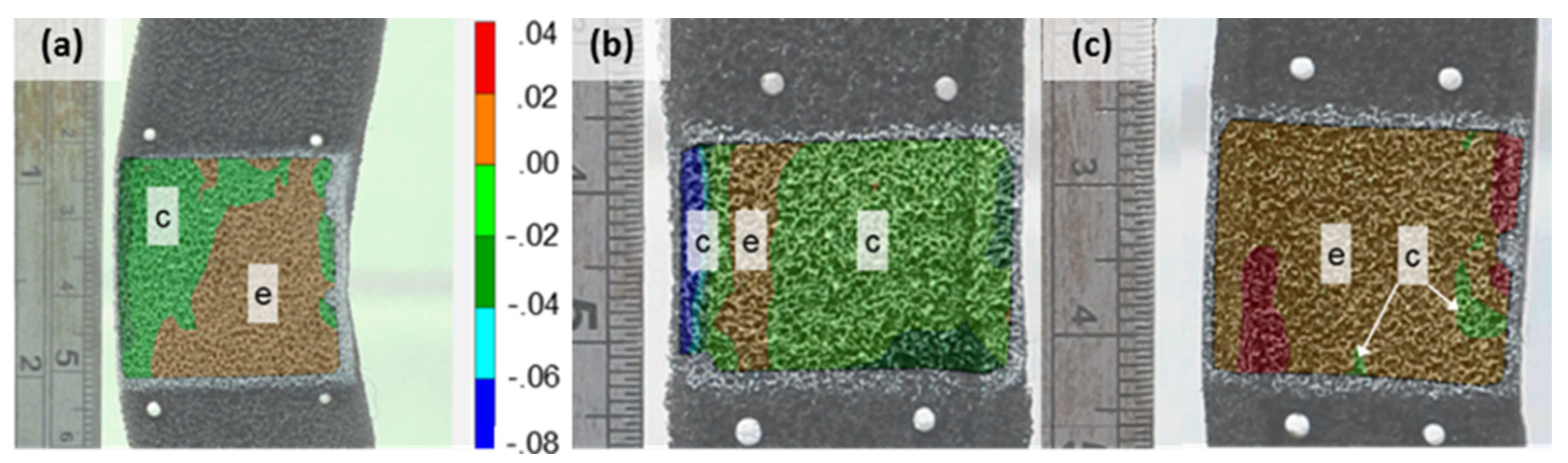
Figure 2b), which exhibited extensive buckling (
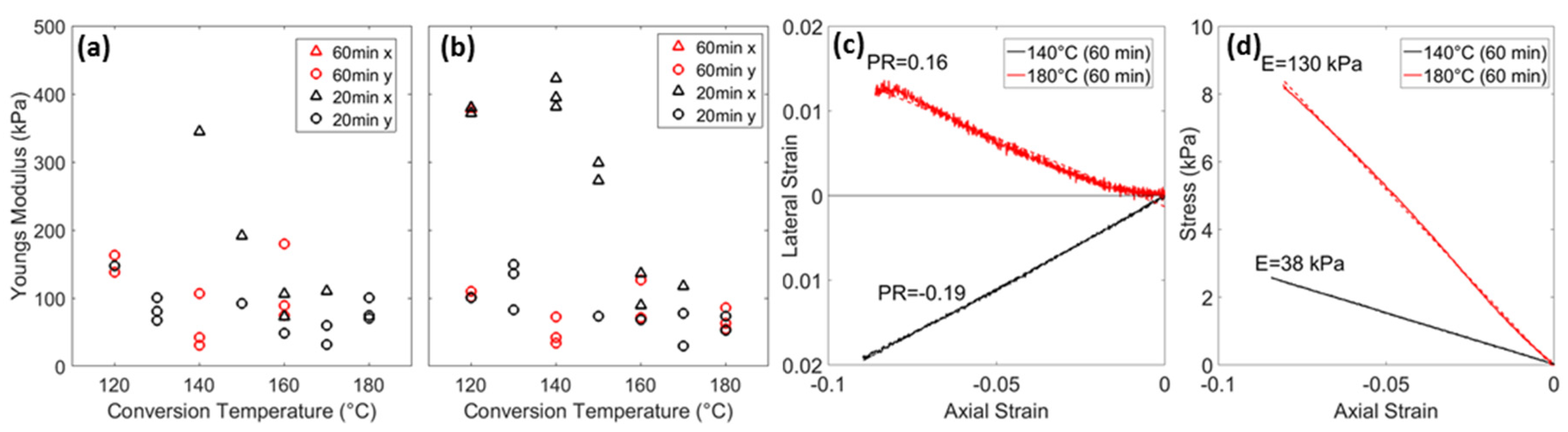
Figure 3a). Buckling also caused low axial strain and high compressive modulus readings, and six unreliable samples have been omitted (
Figure 4a).
Samples that retain compression were less anisotropic than samples that returned to their original dimensions, with similar compressive and tensile modulus (
Figure 4a,b) and Poisson’s ratios (
Figure 2b,c) in different orientations. Samples converted at 180 °C for 60 min exhibited marginally positive compressive Poisson’s ratio (
Figure 2b) and comparable density (within 20%) to NPR samples (140 °C, 60 min, 160 and 170 °C, 20 min,
Figure 2a). Compressive stress/strain relationships of positive and NPR samples (
Figure 4d) were linear (up to 10% compression) but ‘over-heated samples’ (180 °C, 60 min) have a higher modulus (~3 times) than the NPR samples (
Figure 4c). Axial strain/lateral strain relationships (
Figure 4c) were also linear and span positive and negative values. Lateral contraction and expansion were present in different regions of samples (
Figure 3b,c), indicating flaws and heterogeneity. Both the highest magnitude and largest regions of lateral contraction and expansion were present in NPR and conventional samples respectively (
Figure 3b,c).
4. Discussion
Samples converted at short heating times and/or low temperatures return towards their initial dimensions, and long heating times and/or high temperatures cause a positive/near zero Poisson’s ratio, in agreement with previous work [
27,
28,
30]. Both the negative and positive Poisson’s ratios of samples which retain compression were relatively low magnitude (−0.3 to 0.1) and a positive Poisson’s ratio in over-heated samples was only present in compression tests. Select samples do, however, have comparable VCR and therefore density (
Figure 2a), reduced anisotropy (
Figure 2b,c and
Figure 4a,b), linear stress/strain relationships (
Figure 4d) and Poisson’s ratios spanning both positive and negative values (
Figure 2b and
Figure 4c). All samples were simple to fabricate, requiring minimal equipment (a simple mould, PU foam and a conventional oven) and only one heating phase [
19,
30] (facilitating production). Further work should test shape memory, Young’s modulus and Poisson’s ratio after a longer period of time.
Samples which returned towards their original volume [
27,
30] were anisotropic (
Figure 2 and
Figure 4a,b) and Poisson’s ratios above 0.5 were possible [
23,
28] and present (
Figure 2b,c). Behaving as conventional open cell foam with a higher Poisson’s ratio, shear modulus is likely to be low (Equation (1)), increasing the chances of buckling, which was observed in footage recorded for DIC. Strain mapping of buckled samples at full compression (
Figure 3a) shows that axial extension (left hand side) and compression (right hand side) cause lateral contraction and expansion (respectively), in agreement with the theoretically positive Poisson’s ratio. Unconverted samples’ compressive Poisson’s ratios and Young’s modulus were unreliable, but correctly identifying the expected direction of deformation shows how virtual full field strain measurements provided by DIC could supplement future work, particularly force/displacement data in indentation tests.
The combinations of heat and time that produced stable samples (
Figure 2a) with the highest magnitude NPR (~−0.3) in tension and compression were 140 °C for 60 min and 160 °C for 20 min (
Figure 2b,c). Further work could refine conversion protocols in order to fabricate foams with more consistent and higher magnitudes of both positive and negative Poisson’s ratio than presented here. For both heating times, a positive Poisson’s ratio (
Figure 2b,c) was only present in compression in samples towards the highest conversion temperature of 180 °C, although the tensile NPRs of ‘over-heated’ samples were lower in magnitude (between 0 and −0.1) than samples converted at lower temperatures or for shorter times. Further work fabricating samples with different levels of compression, more combinations of temperature and time and with multi-phase conversions are options to attain greater differences in Poisson’s ratio while further controlling density and modulus. An alternative could be to improve the consistency of anisotropic foam fabrications giving modulus in one axis and density comparable to unconverted open cell foam [
31].


 ,
, 


