
A Single-Actuated, Cable-Driven, and Self-Contained Robotic Hand Designed for Adaptive Grasps


Department of Mechanical Engineering, Virginia Polytechnic Institute and State University, Blacksburg, VA 24061, USA
*
Author to whom correspondence should be addressed.
Robotics 2021, 10(4), 109; https://0-doi-org.brum.beds.ac.uk/10.3390/robotics10040109
Submission received: 27 July 2021
/
Revised: 16 September 2021
/
Accepted: 19 September 2021
/
Published: 23 September 2021
(This article belongs to the Section Medical Robotics and Service Robotics)
Abstract
:Developing a dexterous robotic hand that mimics natural human hand movements is challenging due to complicated hand anatomy. Such a practical design should address several requirements, which are often conflicting and force the designer to prioritize the main design characteristics for a given application. Therefore, in the existing designs the requirements are only partially satisfied, leading to complicated and bulky solutions. To address this gap, a novel single-actuated, cable-driven, and self-contained robotic hand is presented in this work. This five-fingered robotic hand supports 19 degrees of freedom (DOFs) and can perform a wide range of precision and power grasps. The external structure of fingers and the thumb is inspired by Pisa/IIT SoftHand, while major modifications are implemented to significantly decrease the number of parts and the effect of friction. The cable configuration is inspired by the tendon structure of the hand anatomy. Furthermore, a novel power transmission system is presented in this work. This mechanism addresses compactness and underactuation, while ensuring proper force distribution through the fingers and the thumb. Moreover, this power transmission system can achieve adaptive grasps of objects with unknown geometries, which significantly simplifies the sensory and control systems. A 3D-printed prototype of the proposed design is fabricated and its base functionality is evaluated through simulations and experiments.
1. Introduction
Prosthetic hand design is an active field of research. However, despite years of development, a compact, self-contained (meaning the hand itself contains all the mechanical and electrical components), and dexterous robotic hand design has remained mostly elusive. Through several research studies, the functionality of robotic hands has been improved by focusing on affordability, portability, weight, design simplicity, number of DOFs, number of actuators, and the ability to provide a safe, powerful, and robust grasp. The design requirements can be summarized in three basic design factors, namely anthropomorphic ([1,2,3,4,5]), underactuated ([3,6,7,8,9]), and compliant ([2,5,10,11,12]) design. With an anthropomorphic design, hand DOFs and natural movements can be reproduced. An underactuated design provides a lightweight, portable, simple, and likely self-contained robotic hand. Lastly, a compliant design helps with robust and safe interaction with the environment. Various design techniques that are used to implement these requirements are discussed as follows.
Generating natural human hand movements is one of the important design requirements. Designs that aim to meet this requirement are often inspired by studies of the human hand anatomy and attempt to implement the same structure and articulation. This design method, referred to as anthropomorphic design, has been used widely in the literature. The detailed biomechanics of the human hand is implemented to replicate the hand dexterity with the price of using up to 10 actuators and mounting them on the forearm [1,2]. Although the appearance of these robotic hands is similar to the human hand articulation, they are massive and not self-contained. It is worth mentioning that being self-contained may not be a necessary requirement for the robotic hand. The human hand itself is not self-contained and most of the muscles that trigger movements of the fingers are in the forearm. However, a self-contained design helps with easily becoming incorporated into the different grasping applications, such as different robotic arms, without any need for additional connection and part-placement considerations.
It is, therefore, evident that anthropomorphic design involves a balancing act between the design simplicity and capturing the human hand dexterity. Considering such trade-off, others have implemented the hand biomechanics structure partially by focusing on replicating the joints’ movement [3,4,5]. Although these latter designs are less similar to the human hand in appearance, they are simple, lightweight, and highly underactuated.
Given the hand’s high number of DOFs and small size, it is extremely challenging to actuate each joint of the robotic hand separately due to space limitations. Therefore, several methods have been used to design underactuated mechanisms [3,6,7,8,9]. Among these methods, the “synergy” idea is a proof that a highly underactuated mechanism can generate the most common hand movements [6,7]. For the first time, synergy was defined in a principal component analysis study on the human hand movements, which showed that hand joint angles are not controlled independently. Additionally, this study showed that the two first principal components, which can be considered to be two sets of hand postures, can reproduce up to 80% of the hand movements, while other principal components provide additional details [13]. This idea does not necessarily provide a simple design but helps with simplifying the control process significantly.
Another common method to design underactuated systems is using differential mechanisms [3,8,9]. These mechanisms distribute the power of the actuator(s) evenly through the engaged joints and can be designed based on levers [8,10,14], pulleys [5], or flexible elements [9]. Additionally, underactuated robotic hands are also implemented through cable-driven designs [4,15], linkage mechanisms [16], or a combination of both methods [17], where each finger is actuated separately. These designs provide the opportunity to control each finger’s movement and perform more complicated tasks, such as object manipulation. Although these types of robotic hands can accommodate a higher variety of postures of the fingers, the synergy idea has proved that a proper power transmission design along with maximum one or two actuators can help with up to 80% of the ADL. Hence, synergy underscores the utility of a single-actuated design, while differential mechanisms provide a pathway to achieving such a design. Even though friction poses a challenge for differential mechanisms, they can enable compact and mostly self-contained designs.
Robotic hands can be fabricated out of soft or rigid material. One of the main shortcomings of a fully rigid robot is that it needs extra safety elements. This is often achieved by adding compliancy to the design. Developing compliant passive parts is a simple implementation of this idea. For instance, elastic elements or springs are used to passively model extension movement of the fingers [2,5,10,11]. Fully soft robotic hand designs using pneumatic actuators have also been proposed [12]. Although the soft pneumatic robotic hand provides a robust and simple design, it needs extra elements (i.e., pressure sensor, pneumatic valve, compressor, and tank) and regular maintenance due to the pneumatic actuators [12]. Therefore, providing a portable and self-contained robotic hand based on soft materials and pneumatic actuators has proven difficult thus far. On the other hand, compliant passive parts add more design flexibility, especially in choosing the type and size of the actuator(s).
Having the three design factors in mind, the Pisa/IIT SoftHand [5] has been found as one of the most encompassing implementations of a robotic hand’s requirements. This robotic hand covers 19 (out of 20) DOFs of the human hand and can reproduce hand movements and grasp postures. The first version of this robotic hand proposed a single actuated design [5]. In the modified version, the synergy idea has been used to improve the design and control system by adding another actuator [18,19]. This cable-driven design is self-contained and can provide robust and safe grasps using passive elastic elements. One cable is used, with a large number of pulleys through the fingers, the thumb, and the palm, to actuate all DOFs. One of the main shortcomings of this design is the high number of parts, which leads to complicated design, fabrication, and assembly processes. Moreover, friction between the tendon and pulleys affects the hand functionality and performance significantly. Tuning friction is extremely challenging and time consuming, and also needs to be done separately and specifically for each assembly. Although this robotic hand can provide precise hand movements, the drawbacks make it less practical.
In this study, the mechanical design of a novel self-contained, cable-driven, and single-actuated robotic hand is presented. The proposed robotic hand strikes a balance among the three abovementioned design factors. The rigid external structure of the thumb and the fingers is inspired by the Pisa/IIT SoftHand [19]. The cable configuration is inspired by the tendon structure of the human hand. Moreover, the combination of the proposed cable configuration and power transmission mechanisms can provide adaptive grasps. The design functionality is evaluated through simulations and using a 3D printed prototype.
The rest of the paper is organized as follows. The design approach and objectives are described briefly in Section 2. The mechanical design of the robotic hand is presented in Section 3, followed by a discussion on the simulation and experimental results in Section 4. The concluding remarks are presented in Section 5.
2. Design Objectives and Approach
The human hand can provide precise movements and grasp postures because of the unique anatomical structures. Replicating all the biological details may lead to a complicated design for a robotic hand, which is not generally desirable. Accordingly, in the proposed design, the main goal is reproducing the hand movements by modeling joints’ DOFs and range of motion (ROM) and performing different grasp types with the minimum required actuation and sensor reading inputs.
Safe interaction of the robotic hand with the environment and the human body is one of the important design concerns. Cable-driven mechanisms can address this requirement by adding more compliance to the design [20,21]. Additionally, these mechanisms can provide a lightweight and potentially compact robotic hand. Therefore, a cable-driven system seems to be a good power transmission candidate for this application.
Underactuation, along with a proper cable-driven power transmission design, can ensure a simple and portable robotic hand. It is important to mention that an underactuated design can limit some of the hand movements, especially when separate control of each joint of the fingers is required (such as object manipulation). However, studies on the human hand movements have shown that the first hand synergy, which is the extension and adduction of Metacarpophalangeal (MCP) joints (the human hand joints and movements will be discussed in the next section), can perform a great range of grasp movements required for activities of daily living (ADL) [7,13]. Moreover, minimizing the number of actuators potentially simplifies the sensory and control systems. Therefore, an underactuated cable-driven mechanism provides a solution for a self-contained robotic hand that can perform a wide range of ADL grasp tasks.
The key design requirements which are addressed through this design can be summarized as supporting human hand DOF and joint’ ROM, being lightweight, compact, safe, simple, and portable.
3. Mechanical Design and Simulation Results
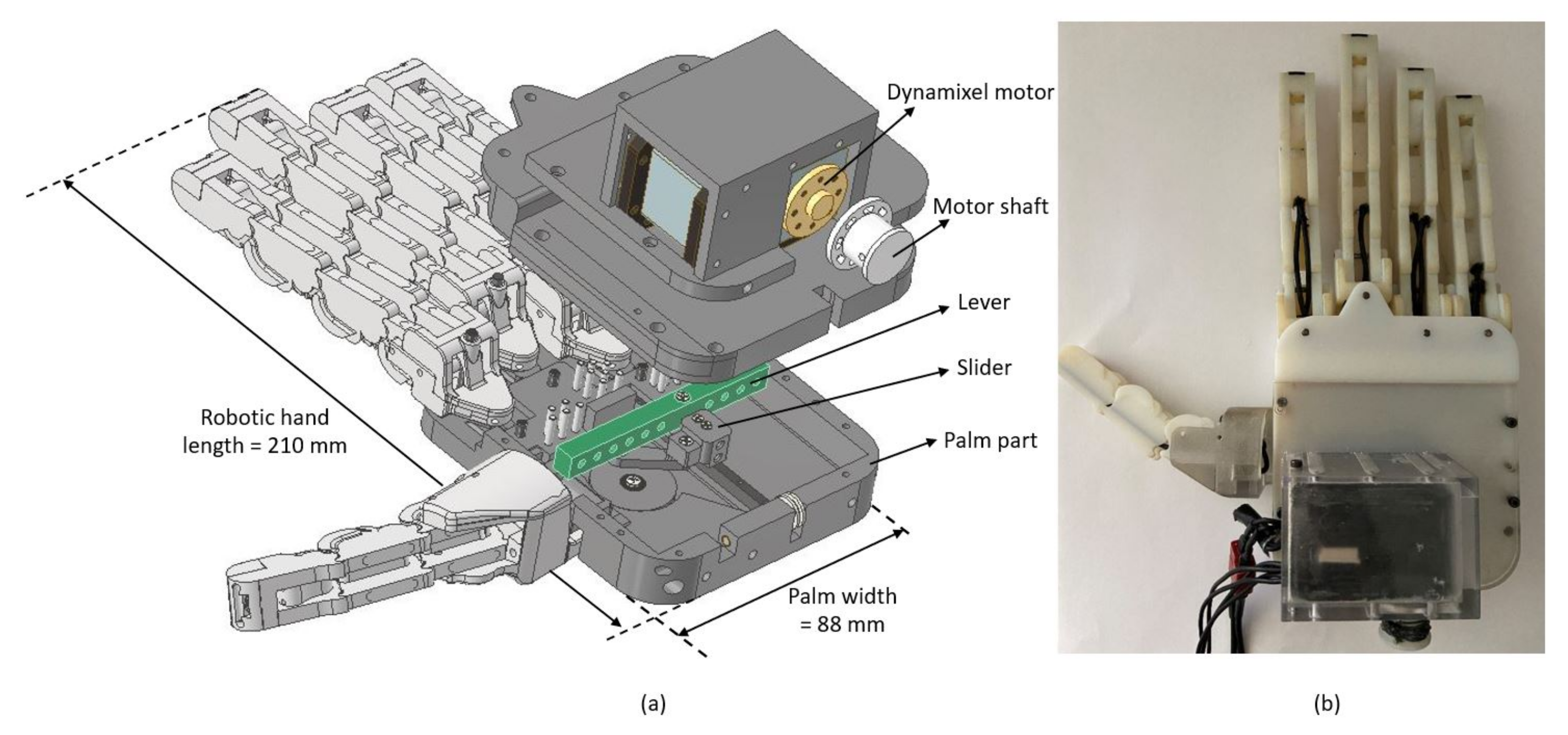
A 3D printed prototype of the proposed robotic hand is shown in Figure 1b. The overall length and thickness of the robotic hand and width of the palm are 210 mm, 62.8 mm, and 88 mm, respectively, as it is shown in Figure 1a. The mechanical design of this robotic hand can be studied in two parts. First, design of thumb and fingers is discussed, where the focus is on supporting all DOFs and joints’ ROM. Then, the power transmission mechanism is explained, which distributes the actuation power between the thumb and fingers. The choice of power transmission system and the employed mechanisms determine important characteristics of the robotic hand, namely single-actuation, self-containment, grasp adaptability, and design, fabrication, and maintenance simplicity.
3.1. Thumb and Fingers Design
To perform a wide range of ADL tasks, the thumb and fingers should provide enough DOFs and ROM. Therefore, a five-fingered robotic hand is proposed which supports 19 DOFs and the complete ROM for each joint. The phalanges, joints, and DOFs of the designed finger is shown in Figure 2. Each finger has 3 joints, namely Distal Interphalangeal (DIP), Proximal Interphalangeal (PIP), and MCP joints, and 4 DOFs. Each of the DIP and PIP joints has one flexion/extension DOF, while the MCP joint has 2 DOFs, namely flexion/extension and abduction/adduction. Similar structure of phalanges is used for the thumb. The only difference is that the thumb has 3 joints and 3 DOFs. Since power and precision grasps are more common and repetitive types for performing ADL, these movements are prioritized in comparison to lateral grasp, where abduction/adduction movement of the thumb is required. Therefore, the abduction/adduction movement of the thumb is not modeled in this design.
The joints’ ROM are reported in Table 1 and compared to the functional ROM of the human hand joints [22], mainly because the main focus of the proposed design is on performing common grasp scenarios through ADL. It is worth mentioning that the maximum ROM of the human hand is more than the reported functional ROM in Table 1. To determine the functional joints’ ROM, angular movements of the joints are measured while healthy subjects are asked to perform some ADL, such as holding a cup or turning a key [22]. As it can be seen in Table 1, the ROM of the thumb MCP joint is out of the reported ROM in [22]. Since abduction/adduction joint of the thumb is not modeled in the presented design, a broader ROM for MCP joint is required for performing reliable grasps.
The rigid external structure of the thumb and fingers is inspired by the Pisa/IIT SoftHand [19] and major modifications have been implemented to improve the fingers functionality. In the Pisa/IIT SoftHand design, one structure of a phalange is repeated to create the whole finger or thumb. The phalange design of the Pisa/IIT SoftHand is shown in Figure 3a. To ensure an accurate movement of the joints, a partially geared coupling is designed on the rolling surface of each side parts. Elastic elements are considered to keep the phalanges together, constrain the gear contacts, increase the system elasticity, provide a safe grasp, and passively extend the fingers. Another interesting feature of this design is that the thumb and fingers do not have any mechanical joints, while all human thumb and finger joints are modeled (excluding thumb abduction/adduction DOF). This feature helps with simpler and faster assembly process. Despite all the advantages of the Pisa/IIT SoftHand design, it still has some shortcomings which decrease the hand functionality significantly.
The major drawback of the Pisa/IIT SoftHand design is the large number of parts. As it can be seen in Figure 3a, each phalange is composed of 12 parts. More specifically, a large number of pulleys (26 pulleys for one finger assembly, without considering the large number of pulleys in the palm section) is used in this design, which magnify the effect of friction and slow down the fabrication and assembly processes. Moreover, derailment is one of the challenges of the cable and pulley system implementation. This happens when the cable pretension is not tuned accurately. The large number of pulleys increases the chance of derailment. Furthermore, the assembly and maintenance processes of the Pisa/IIT SoftHand are more complicated and time consuming due to the large number of parts and small size of pulleys. Additionally, the cable configuration needs to be tuned separately and specifically for each assembled hand to minimize friction. In the proposed design, these shortcomings are addressed.
The proposed phalange design is shown in Figure 3b. The number of parts is reduced significantly (from 12 parts for each phalange in the Pisa/IIT SoftHand [19] to only one part in the proposed design). In the proposed design, all pulleys through the thumb and fingers are eliminated. These modifications simplify the design and consequently, speed up the fabrication and assembly processes significantly. Moreover, derailment, friction, and tuning concerns are addressed.
The cable configuration of the proposed design is inspired by the tendon structure of the hand anatomy. The human hand Flexor tendons are responsible for bending the thumb and fingers and help with grasping objects. These tendons are connected to the forearm bones from one side and to the Intermediate and Distal phalanges bones from the other end. To implement the same configuration on the robotic hand, a set of cable guides is designed for each phalange. These cable guides imitate the human hand ligaments and restrict the cable to move alongside the designed thumb and fingers. The proposed cable configuration is shown in Figure 4. For the Distal phalange, the cable guide has two parts: closer to the DIP joint, the guide is a straight channel starting at the palmar side, and at the fingertip, it is a U-shaped channel at the dorsal side of the phalange. This configuration helps with maximizing the normal component of the contact force at the fingertip. For other phalanges, the guide is a straight line at the palmar side to maximize the moment arm and consequently the moment at each joint. Additionally, in comparison to the pulley system of the Pisa/IIT SoftHand (Figure 3a), sharp curvatures of the configured cable around the pulleys are replaced with straight channels. This design of the cable guides significantly helps with reducing friction.
Flexion movement of DIP, PIP, IP, and MCP joints are achieved actively by reducing the length of the cable through the thumb and fingers using the proposed cable-driven power transmission mechanism. Abduction/adduction DOF of the fingers and flexion/extension DOF of the Carpometacarpal (CMC) joint of the thumb are actuated passively using a pin at the base of the fingers. This passive design provides enough ROM for the fingers’ MCP joints to abduct (move the fingers away from the middle of the hand) and easier grasp different size and geometry of objects. However, routing the cables through the set of pins, which are incorporated into the pretension mechanism and discussed in Section 3.2.3, constrains this passive movement. Therefore, the pretension mechanism along with the elasticity of the cables ensure the joints’ elasticity and prevent them from moving loosely. Extension movement of the thumb and fingers are generated by elastic elements, which are incorporated along the dorsal side of the phalanges. The elastic elements are 2 mm round heavy elastic bands. The schematic of this elastic element can be seen in the top portion of Figure 4, in black color.
3.2. Power Transmission System Design
For a robust and powerful grasp, it is crucial to distribute the actuation force properly between the thumb and fingers. The proposed power transmission system, which is shown in Figure 5, presents a compact, lightweight, and simple implementation of a single-actuated and cable-driven robotic hand. One piece of cable, which is marked as actuation cable in Figure 5, is attached to the motor shaft from one end and is tied to the slider from the other end. This cable is responsible to pull the slider along the palm and actuate palm mechanisms. These mechanisms ensure accurate movement of the thumb and fingers and are designed and implemented as follows.
3.2.1. Differential Mechanism
Grasp posture and contact forces are important elements of an effective grasp. This mechanism is designed to sync the movement of the fingers and distribute the actuation force between them. The CAD model of this mechanism is shown in Figure 6a.
The differential mechanism consists of a lever, at which the cables of the fingers are tied. The lever is hinged to the slider, which travels along the palm and pulls the cables. The cables of the fingers are tied to the lever at specific tie points. The tie points are positioned to maximize the cable forces of the index and middle fingers (as they are involved in most grasp types) and minimize the force difference among all fingers (to synchronize movement of fingers). The former requirement determines on which side of the hinge a particular tie point should be placed, while the latter can be met by optimizing the relative distance between the tie points and the hinge. This can be formulated as the following optimization problem.
where denotes the distance of each tie point from the hinge and
denotes the vector of cable forces through the fingers. Based on the design geometric constraints and material strength, design parameters are determined to be mm, mm, and mm, in order to restrict the minimum distance of the tie points from the hinge connection, the lever ends, and other tie points, respectively.
The differential mechanism can also contribute to developing adaptive grasps, which is the ability of the robotic hand to grasp objects with unknown geometries. This characteristic simplifies the control and sensory systems of the robotic hand. Therefore, the position of tie points are determined to achieve this goal. Since index and middle fingers are involved in most types of grasp, each tie point should be placed on one side of the lever, with respect to the hinge. This choice of layout ensures a strong and robust grasp, even when one of these two fingers is blocked because of the geometry of the object.
Several simulations in Adams software are conducted to search the design space based on the defined optimization problem. The Adams cable modeling toolbox makes it a powerful software for modeling this design. The material of the cable is tuned through the Young’s modulus parameter of the cable. Moreover, the passive elastic elements are modeled as springs [23]. In this set of simulations, it is assumed that the cables of the ring and little fingers are tied to one point, where mm. This assumption was motivated by the space limitation concerns. The cable forces are studied while the position of middle and index fingers’ tie points (i.e., and ) and the length of the lever are changed through a determined parameter grid. Parameter bounds are defined based on empirical observations in several primary experiments conducted during initial design iterations. Space limitation was also considered in defining the bounds. Accordingly, parameters and are chosen in the range of [16, 34.5] mm and [2, 16] mm, respectively. On the other hand, a binary choice is considered for the lever’s length, which is either 60 mm or 74 mm. A total of 30 points from this parameter space are used for simulations. The points are selected to cover the parameter space, with more points chosen in regions where better solutions were found from initial simulations. Figure 7 shows the summarized result of these simulations.
Results of a similar simulation for two different length of the lever is shown in Figure 7a. Less variance values of the longer lever, where mm, shows that the force is distributed more evenly between the fingers. For simulations with the longer lever, the fingers postures of two simulations are demonstrated in Figure 7b and the corresponding cable forces are shown in Figure 7c. It can be seen that despite the similar force distribution, the fingers may exhibit different postures. Therefore, it appears that proper force distribution alone is not sufficient to optimize the grasp posture and fine tuning is still needed to improve the fingers movements.
To address these concerns, a few holes are considered along the lever to provide more tuning flexibility. Moreover, using a longer lever and considering more holes allows for separating the tie points for little and ring fingers. This was found to lead to better tuned postures of the robotic hand. Therefore, in the final design, each finger is tied to a separate point, where mm, mm, mm, and mm.
3.2.2. Slider-Crank Mechanism
This mechanism is highlighted in Figure 8a. It synchronizes the thumb and the fingers movement and allows the thumb and fingers to bend simultaneously and provide a natural grasp. Schematic of this mechanism is shown in Figure 8b. The slider moves along the palm. The thumb’s cable is tied to the pulley. Therefore, the thumb flexes and its cable is pulled when the pulley rotates. The mechanism parameters are tuned so that full travel of the slider along the palm (distance d in Figure 8b), which causes the fingers flexion, reduces enough cable length through the thumb () to completely flex it, as well.
3.2.3. Pretension Mechanism
To tune the initial position of the fingers, a pretension mechanism is considered. This mechanism adjusts the initial posture of the fingers by reducing the cable length through the fingers. Therefore, determining the relationship between the cable length reduction and the joint angles can provide valuable information about the requirements and tuning process of the pretension mechanism and movement of the fingers.
Here, this relationship is derived for the index finger. The parametric model of one joint of the finger is shown in Figure 9, where is the joint angle, is the initial free cable length, and is the free cable length at position of the joint, and represents the MCP, PIP, and DIP joints, respectively. , , and are the joint geometric parameters. The cable length reduction due to rotation of the ith joint can be written as
where
and can be calculated using the joint geometry and cosine rule,
As seen in (5), is a function of the joint angle and the geometry parameters , , and . Therefore, considering a set of finger joint angles, the total cable length reduction through the finger is
The inverse kinematic of a single finger can be solved using (3)–(6) to determine how much cable should be pulled to achieve a desired finger posture (desired MCP, PIP, and DIP joint angles). Through this analysis, it is assumed that the finger performs a free flex, meaning that the finger is bending without any obstacle blocking its joint space. Therefore, (3)–(6) are not valid for grasp analysis.
A simulation in Simscape/Simulink environment is conducted to determine the finger posture corresponding to a specific amount of cable length reduction through the finger. First, the simulated finger model is validated using the derived inverse kinematic. With a specific set of joint angles, the cable length reduction is calculated from both the analytical equations and the simulation. Figure 10 shows this comparison for a specific set of joint angles, where the results of both methods match closely. The reason for the slight deviation of the Simulink results from the analytical calculations can be the difference in the parameters used for the two cases. Specifically, the Simulink model is based on the CAD model of a finger assembly, whereas the geometry parameters used in the analytical study are simple approximations of the true geometry.
Having validated the simulation model with the analytical approach, the model is used to estimate the joint angles corresponding to the cable length reduction of the finger. The result of this simulation is demonstrated in Figure 11. Joint angles for four selected values of cable length reduction are highlighted in the figure and the corresponding finger postures are demonstrated. It is evident that for 15.7 mm cable length reduction, the finger’s joints have reached their maximum ROM. This information is used to determine the sliding course of the differential mechanism and parameters of the slider-crank mechanism. Moreover, Figure 11 shows that even 3.92 mm cable length reduction through the finger leads to almost 20 degree joint angles, which are considerable amounts of flexion. Therefore, a mechanism with fine tuning capability is required to implement the desired pretension of the cables. The implementation uncertainties, such as the variations in the elastic band stiffness, further highlight the need for fine tuning of cable pretensions.
Functionality of several pretension mechanisms were assessed. For instance, a ratchet and pawl mechanism was considered due to the accurate tuning system. However, space limitations rendered this mechanism less practical for this design. Moreover, the mechanism could not offer the required fine-tuned pretension. Therefore, an alternative approach, shown in Figure 12 is considered here. Specifically, a mesh of pins is mounted on the palm and close to the base of the fingers. The cables are routed through this mesh of pins during assembly to apply the desired pretension. Moreover, a set of pins are considered closer to the base of the fingers to ensure that the rotation of the lever does not cause unwanted abduction/adduction movement through the fingers. This approach leads to a simple design and flexible tuning.
Combination of the three abovementioned mechanisms (Differential, Slider-Crank, and pretension mechanisms) provide a simple design. In comparison to the Pisa/IIT SoftHand [19], the number of parts at the palm is significantly reduced, which plays an important role in simplifying and speeding up the fabrication and assembly processes. Moreover, the resulting robotic hand is lightweight and consequently portable. The small number of parts guarantees compactness and self-containment due to the possibility of mounting all the components on the palm. Additionally, using the differential mechanism helps with single-actuation of the robotic hand and performing adaptive grasps. The robotic hand functionality is evaluated through experiments, as explained in the next section.
3.3. Fabrication
A prototype of the proposed design is 3D printed. Most of the parts are printed with Vero material using a Connex3 3D printer, since they are not under high actuation or external loads. Finite element analysis (FEA) results have shown that the stress distribution of some of the differential mechanism parts is beyond the yield strength of the Vero material. Therefore, these parts are 3D printed using Titanium.
Different types of cables are evaluated to decrease friction while supporting enough tensile load. Fishing lines have been found as the best options. Based on the experiments, among the fishing lines, monofilament lines can best minimize friction. The elastic elements that have been used for the passive extension movements are 2 mm round elastic bands.
4. Experimental Evaluation
The functionality of the proposed design is evaluated through simulations and experiments. The robotic hand design is modeled in the Simscape/Simulink environment to assess the finger postures and study the relationship between the cable length reduction and the joint angles through a finger, which is discussed in Section 3.2.3. Moreover, a simulation is conducted in Adams software to study the differential mechanism functionality and approximately determine the position of cables tie points, as was explained in the previous section.
A 3D printed prototype of the robotic hand is fabricated. The designed mechanism is actuated using a Dynamixel motor (RX-28). Power and precision grasps are common and repetitive grasp postures among ADL. Figure 13 shows these types of grasps, performed by the robotic hand prototype.
To evaluate the robotic hand functionality in performing adaptive grasps, the hand prototype is actuated while one of the fingers is blocked through each experiment. Figure 14 shows the fingers posture in each test. As it can be seen, blocking one finger does not restrict the movement of other fingers. Therefore, the robotic hand can perform adaptive grasps and grasp objects with unknown geometries.
5. Conclusions
In this paper, a novel design of a robotic hand is presented. With the proposed design, one actuator (Dynamixel RX-28) is used to perform adaptive grasps, while extension movements are implemented passively using elastic elements. This cable-driven robotic hand can grasp a wide range of objects with unknown geometries using a novel power transmission mechanism. A 3D-printed prototype is used to verify the final design, where experimental evaluations reveal the proposed design meets the design requirements and can perform a wide range of power and precision grasps.
As for the shortcomings of the current design, since the abduction/adduction movement of the thumb is not modeled, the proposed robotic hand is not able to perform lateral grasps. Furthermore, an open loop actuation is considered for experimental validations at this point. Therefore, grasping soft and deformable objects are not studied in this set of experiments due to the lack of tactile feedback. The future work will be mainly focused on developing a more compact actuation setup and providing further quantification of the robotic hand’s performance.
Author Contributions
Conceptualization, N.N. and A.L.; Methodology, N.N.; Project administration, A.L.; Resources, A.L.; Supervision, A.L.; Validation, N.N.; Writing—original draft, N.N.; Writing—review & editing, A.L. Both authors have read and agreed to the published version of the manuscript.
Funding
This research was funded by the National Science Foundation under Grants No. 1718801.
Institutional Review Board Statement
Not applicable.
Informed Consent Statement
Not applicable.
Data Availability Statement
Not applicable.
Acknowledgments
The authors would like to thank Antonio Bicchi for providing the CAD files of the Pisa/IIT SoftHand, as well as constant feedback during the design process.
Conflicts of Interest
The authors declare no conflict of interest. The funders had no role in the design of the study; in the collection, analyses, or interpretation of data; in the writing of the manuscript, or in the decision to publish the results.
References
- Xu, Z.; Todorov, E. Design of a highly biomimetic anthropomorphic robotic hand towards artificial limb regeneration. In Proceedings of the 2016 IEEE International Conference on Robotics and Automation (ICRA), Stockholm, Sweden, 16–21 May 2016; pp. 3485–3492. [Google Scholar]
- Dalley, S.A.; Wiste, T.E.; Withrow, T.J.; Goldfarb, M. Design of a multifunctional anthropomorphic prosthetic hand with extrinsic actuation. IEEE/ASME Trans. Mechatron. 2009, 14, 699–706. [Google Scholar] [CrossRef]
- Leddy, M.T.; Dollar, A.M. Preliminary design and evaluation of a single-actuator anthropomorphic prosthetic hand with multiple distinct grasp types. In Proceedings of the 2018 7th IEEE International Conference on Biomedical Robotics and Biomechatronics (Biorob), Enschede, The Netherlands, 26–29 August 2018; pp. 1062–1069. [Google Scholar]
- Mohammadi, A.; Lavranos, J.; Zhou, H.; Mutlu, R.; Alici, G.; Tan, Y.; Choong, P.; Oetomo, D. A practical 3D-printed soft robotic prosthetic hand with multi-articulating capabilities. PLoS ONE 2020, 15, e0232766. [Google Scholar] [CrossRef] [PubMed]
- Catalano, M.G.; Grioli, G.; Farnioli, E.; Serio, A.; Piazza, C.; Bicchi, A. Adaptive synergies for the design and control of the Pisa/IIT SoftHand. Int. J. Robot. Res. 2014, 33, 768–782. [Google Scholar] [CrossRef] [Green Version]
- Catalano, M.G.; Grioli, G.; Serio, A.; Farnioli, E.; Piazza, C.; Bicchi, A. Adaptive synergies for a humanoid robot hand. In Proceedings of the 2012 12th IEEE-RAS International Conference on Humanoid Robots (Humanoids 2012), Osaka, Japan, 29 November–1 December 2012; pp. 7–14. [Google Scholar]
- Brown, C.Y.; Asada, H.H. Inter-finger coordination and postural synergies in robot hands via mechanical implementation of principal components analysis. In Proceedings of the 2007 IEEE/RSJ International Conference on Intelligent Robots and Systems, San Diego, CA, USA, 29 October–2 November 2007; pp. 2877–2882. [Google Scholar]
- Mottard, A.; Laliberté, T.; Gosselin, C. Underactuated tendon-driven robotic/prosthetic hands: Design issues. In Proceedings of the Robotics: Science and Systems 2017, Cambridge, MA, USA, 12–16 July 2017. [Google Scholar]
- Xu, K.; Liu, H.; Liu, Z.; Du, Y.; Zhu, X. A single-actuator prosthetic hand using a continuum differential mechanism. In Proceedings of the 2015 IEEE International Conference on Robotics and Automation (ICRA), Seattle, WA, USA, 26–30 May 2015; pp. 6457–6462. [Google Scholar]
- Hussain, I.; Iqbal, Z.; Malvezzi, M.; Seneviratne, L.; Gan, D.; Prattichizzo, D. Modeling and Prototyping of a Soft Prosthetic Hand Exploiting Joint Compliance and Modularity. In Proceedings of the 2018 IEEE International Conference on Robotics and Biomimetics (ROBIO), Kuala Lumpur, Malaysia, 12–15 December 2018; pp. 65–70. [Google Scholar]
- Ke, A.; Huang, J.; He, J. An Underactuated Prosthetic Hand with Coupled Metacarpophalangeal Joints. J. Adv. Comput. Intell. Intell. Inform. 2018, 22, 674–682. [Google Scholar] [CrossRef]
- Deimel, R.; Brock, O. A novel type of compliant and underactuated robotic hand for dexterous grasping. Int. J. Robot. Res. 2016, 35, 161–185. [Google Scholar] [CrossRef] [Green Version]
- Santello, M.; Flanders, M.; Soechting, J.F. Postural hand synergies for tool use. J. Neurosci. 1998, 18, 10105–10115. [Google Scholar] [CrossRef] [PubMed]
- Baril, M.; Laliberte, T.; Gosselin, C.; Routhier, F. On the design of a mechanically programmable underactuated anthropomorphic prosthetic gripper. J. Mech. Des. 2013, 135, 121008. [Google Scholar] [CrossRef]
- Liow, L.; Clark, A.B.; Rojas, N. Olympic: A modular, tendon-driven prosthetic hand with novel finger and wrist coupling mechanisms. IEEE Robot. Autom. Lett. 2019, 5, 299–306. [Google Scholar] [CrossRef]
- Imbinto, I.; Montagnani, F.; Bacchereti, M.; Cipriani, C.; Davalli, A.; Sacchetti, R.; Gruppioni, E.; Castellano, S.; Controzzi, M. The S-Finger: A synergetic externally powered digit with tactile sensing and feedback. IEEE Trans. Neural Syst. Rehabil. Eng. 2018, 26, 1264–1271. [Google Scholar] [CrossRef] [PubMed]
- Slade, P.; Akhtar, A.; Nguyen, M.; Bretl, T. Tact: Design and performance of an open-source, affordable, myoelectric prosthetic hand. In Proceedings of the 2015 IEEE International Conference on Robotics and Automation (ICRA), Seattle, WA, USA, 26–30 May 2015; pp. 6451–6456. [Google Scholar]
- Della Santina, C.; Grioli, G.; Catalano, M.; Brando, A.; Bicchi, A. Dexterity augmentation on a synergistic hand: The Pisa/IIT SoftHand+. In Proceedings of the 2015 IEEE-RAS 15th International Conference on Humanoid Robots (Humanoids), Seoul, Korea, 3–5 November 2015; pp. 497–503. [Google Scholar]
- Della Santina, C.; Piazza, C.; Grioli, G.; Catalano, M.G.; Bicchi, A. Toward dexterous manipulation with augmented adaptive synergies: The pisa/iit softhand 2. IEEE Trans. Robot. 2018, 34, 1141–1156. [Google Scholar] [CrossRef]
- Kim, Y.J. Anthropomorphic low-inertia high-stiffness manipulator for high-speed safe interaction. IEEE Trans. Robot. 2017, 33, 1358–1374. [Google Scholar] [CrossRef]
- Tang, L.; Gouttefarde, M.; Sun, H.; Yin, L.; Zhou, C. Dynamic modelling and vibration suppression of a single-link flexible manipulator with two cables. Mech. Mach. Theory 2021, 162, 104347. [Google Scholar] [CrossRef]
- Hume, M.C.; Gellman, H.; McKellop, H.; Brumfield, R.H., Jr. Functional range of motion of the joints of the hand. J. Hand Surg. 1990, 15, 240–243. [Google Scholar] [CrossRef]
- MSC. Supplemental Adams Tutorial Kit. Available online: https://www.mscsoftware.com/sites/default/files/Book_Adams-Tutorial-ex17-w.pdf (accessed on 20 September 2021).
Figure 1.
(a) The partially exploded view of the proposed robotic hand CAD model, (b) The 3D printed prototype of the presented robotic hand.
Figure 1.
(a) The partially exploded view of the proposed robotic hand CAD model, (b) The 3D printed prototype of the presented robotic hand.

Figure 2.
The proposed finger design elements: phalanges, joints, and DOFs.

Figure 3.
(a) The partially exploded sketch of one phalange of the Pisa/IIT SoftHand and its cable configuration [19], (b) The proposed phalange design and its cable configuration.
Figure 3.
(a) The partially exploded sketch of one phalange of the Pisa/IIT SoftHand and its cable configuration [19], (b) The proposed phalange design and its cable configuration.

Figure 4.
Schematic of the elastic band and the proposed cable configuration of the thumb and fingers.
Figure 4.
Schematic of the elastic band and the proposed cable configuration of the thumb and fingers.

Figure 5.
Power transmission mechanism of the proposed robotic hand, (a) 3D printed prototype, (b) CAD model.
Figure 5.
Power transmission mechanism of the proposed robotic hand, (a) 3D printed prototype, (b) CAD model.

Figure 6.
Differential mechanism of the proposed robotic hand, (a) CAD model, (b) design parameters.
Figure 6.
Differential mechanism of the proposed robotic hand, (a) CAD model, (b) design parameters.

Figure 7.
Results of ADAMS simulations, (a) one sample of variance comparison for two different lengths of the lever, (b) posture of fingers for two set of simulations with mm, (c) cable forces for the same simulations of part (b), where mm.
Figure 7.
Results of ADAMS simulations, (a) one sample of variance comparison for two different lengths of the lever, (b) posture of fingers for two set of simulations with mm, (c) cable forces for the same simulations of part (b), where mm.

Figure 8.
Slider-Crank mechanism, (a) the CAD model, (b) schematic of the linkage mechanism.

Figure 9.
Schematic of a finger joint.

Figure 10.
Comparison of numerical simulation and analytical calculation for cable length reduction for a specific set of joint angles.
Figure 10.
Comparison of numerical simulation and analytical calculation for cable length reduction for a specific set of joint angles.

Figure 11.
Joint angle and finger posture variations with the cable length reduction.

Figure 12.
A CAD model of the pretension mechanism.

Figure 13.
Examples of different grasps performed by the robotic hand prototype, (a,b) power grasps, (c–f) precision grasps.
Figure 13.
Examples of different grasps performed by the robotic hand prototype, (a,b) power grasps, (c–f) precision grasps.

Figure 14.
Differential mechanism functionality for providing adaptive grasps, (top row) the posture of fingers while each finger is blocked, (bottom row) the state of power transmission system for the corresponding movement of fingers.
Figure 14.
Differential mechanism functionality for providing adaptive grasps, (top row) the posture of fingers while each finger is blocked, (bottom row) the state of power transmission system for the corresponding movement of fingers.


Publisher’s Note: MDPI stays neutral with regard to jurisdictional claims in published maps and institutional affiliations. |
© 2021 by the authors. Licensee MDPI, Basel, Switzerland. This article is an open access article distributed under the terms and conditions of the Creative Commons Attribution (CC BY) license (https://creativecommons.org/licenses/by/4.0/).
Share and Cite
MDPI and ACS Style
Nikafrooz, N.; Leonessa, A. A Single-Actuated, Cable-Driven, and Self-Contained Robotic Hand Designed for Adaptive Grasps. Robotics 2021, 10, 109. https://0-doi-org.brum.beds.ac.uk/10.3390/robotics10040109
AMA Style
Nikafrooz N, Leonessa A. A Single-Actuated, Cable-Driven, and Self-Contained Robotic Hand Designed for Adaptive Grasps. Robotics. 2021; 10(4):109. https://0-doi-org.brum.beds.ac.uk/10.3390/robotics10040109
Chicago/Turabian StyleNikafrooz, Negin, and Alexander Leonessa. 2021. "A Single-Actuated, Cable-Driven, and Self-Contained Robotic Hand Designed for Adaptive Grasps" Robotics 10, no. 4: 109. https://0-doi-org.brum.beds.ac.uk/10.3390/robotics10040109
Note that from the first issue of 2016, this journal uses article numbers instead of page numbers. See further details here.