Article

Design of Multiple Wearable Robotic Extra Fingers for Human Hand Augmentation

by
Monica Malvezzi
1,*,
Zubair Iqbal
1,
Maria Cristina Valigi
2,
Maria Pozzi
1,3,
Domenico Prattichizzo
1,3 and
Gionata Salvietti
1,3
1
Department of Information Engineering and Mathematics, University of Siena, 53100 Siena, Italy
2
Department of Engineering, University of Perugia, Via G. Duranti, 1–06125 Perugia, Italy
3
Department of Advanced Robotics, Istituto Italiano di Tecnologia, 16163 Genoa, Italy
*
Author to whom correspondence should be addressed.
Submission received: 4 November 2019 / Revised: 6 December 2019 / Accepted: 8 December 2019 / Published: 11 December 2019
(This article belongs to the Special Issue Advances in Italian Robotics)

Abstract

:
Augmenting the human hand with robotic extra fingers is a cutting-edge research topic and has many potential applications, in particular as a compensatory and rehabilitation tool for patients with upper limb impairments. Devices composed of two extra fingers are preferred with respect to single finger devices when reliable grasps, resistance to external disturbances, and higher payloads are required. Underactuation and compliance are design choices that can reduce the device complexity and weight, maintaining the adaptability to different grasped objects. When only one motor is adopted to actuate multiple fingers, a differential mechanism is necessary to decouple finger movements and distribute forces. In this paper, the main features of a wearable device composed of two robotic extra fingers are described and analyzed in terms of kinematics, statics, and mechanical resistance. Each finger is composed of modular phalanges and is actuated with a single tendon. Interphalangeal joints include a passive elastic element that allows restoring the initial reference configuration when the tendon is released. The stiffness of each passive element can be customized in the manufacturing process and can be chosen according to a desired closure movement of the fingers. Another key aspect of the device is the differential system connecting the actuator to the fingers.

1. Introduction

1.1. Robotic Hands

Robotic hands have represented a challenge for designers and engineers for at least three decades [1] due to the complexity of grasping and manipulation tasks and device limits [2]. Although several interesting solutions have been presented in the literature, there are still open challenges. There are hands that have an anthropomorphic structure [3,4], and others that exploit underactuation and parallel kinematic structures to gain adaptability to the grasped objects [5]. Applications range from humanoids [3,6], to prostheses [7], to space applications [5]. Different types of actuations have been implemented, not limited to electro-mechanic transmissions. In [8], for instance, pneumatic systems are adopted, while in [9], Shape Memory Alloy were used. Underactuation [10,11,12] and modularity [13] are aspects that are investigated to reduce the complexity of the hand by maintaining a suitable level of performance. Also, transmission systems have a great importance in robotic hands, as described in [14], where different transmission systems are compared for different robotic hands. Tendon-driven mechanisms have been widely used in articulated-finger robotic hands. In [15], several interesting issues on tendon-driven mechanisms are discussed, with a focus on tendon redundancy and joint stiffness adjustability for a robotic mechanism driven with redundant tendons.

1.2. Wearable Robotic Extra Fingers

More recently, a new branch in robotics research, involving both robotic hands and human-robot interaction problems, was born: it is referred to as human augmentation and consists in developing wearable robotic systems that are supplementary with respect to human body structure [16,17]. A particularly interesting application of wearable robotic extra limbs is introduced in [18]: the proposed device is a modular robotic extra finger that can be worn by a user as a bracelet and augments the human hand in terms of workspace and manipulation capabilities. An underactuated version of this device has been introduced in [19] to assist patients with limited hand and arm functions for instance after a stroke event. Another implementation of wearable robotic extra fingers is presented in [20], in which a pair of soft robotic fingers driven by tendons and servomotors are worn on a human hand and lay on the same plane of the palm, working as two additional thumbs. In applications in which wearable extra fingers are used as compensatory devices, although the availability of a wearable robotic extra-finger opposed to the paretic limb allows the patient a stable hold for a large number of objects, a solution with two or multiple fingers could further help the user when performing some activities requiring higher payloads and grasp stability [21].

1.3. Underactuation in Robotic Extra Fingers

Underactuation is an important aspect to be considered in designing safe and robust robotic hands and fingers. Reducing the number of actuators is particularly important in wearable devices, in which the weight and the complexity should be reduced as much as possible. In general, an underactuated mechanism is defined as a mechanism that has fewer actuators than degrees of freedom. In robotic hands, it is important to notice that underactuation can provide interesting properties to the device, like for instance self adaptability [22]. However, reducing the number of actuated degrees of freedom (DoFs) may decrease the overall manipulability properties and the capability to adapt to different shapes and dimensions of grasped objects. For single-finger robotic devices, these properties can be partially recovered by means of compliance, that in the wearable device introduced in [19] has been implemented by passive elastic elements in interphalangeal joints.

1.4. Differential Mechanisms

In devices composed of more than one finger, however, joint compliance is not enough to guarantee the adaptability to the different shapes of grasped objects. If one motor is employed directly to drive simultaneously the opening and closing motion of the fingers, when a finger is blocked, due to the contact with an object or a surface, the other one will stop, too. A differential mechanism is therefore necessary in devices composed of multiple fingers actuated with a single motor. For a double robotic extra finger, that is a device with two outputs and one input, a simple differential mechanism can be used to decouple finger motions when one of them is constrained. In general, a differential is a mechanism with two-degrees of freedom able to transform a single input into two outputs. The role of the differential mechanism is to distribute an input force/torque F a between two outputs, F 1 a and F 2 a , so that F a = F 1 a + F 2 a . In the literature, there are many applications of differential mechanisms for robotic fingers and hands [23]. In [24], a differential system based on gears is used for a novel architecture of robotic hand and the properties of differential mechanisms arranged in cascade via parallel or serial connections is studied. In [25], a planetary gear solution and a fluid T-pipe scheme are described. In [26], a moving pulley differential mechanism was used, while in [3] a differential with a T-shape fluid mechanism and the connected seesaw circuit is presented. In [27], an underactuated anthropomorphic gripper for prosthetic applications was presented, in which a mechanical lever inside the palm allowed to extend the grasping capabilities and improve the force transmission ratio of the gripper. This mechanism was further developed in [28], in which the differential mechanism included a set of locking buttons allowing the user to stop the motion of each finger.

1.5. Paper Contribution
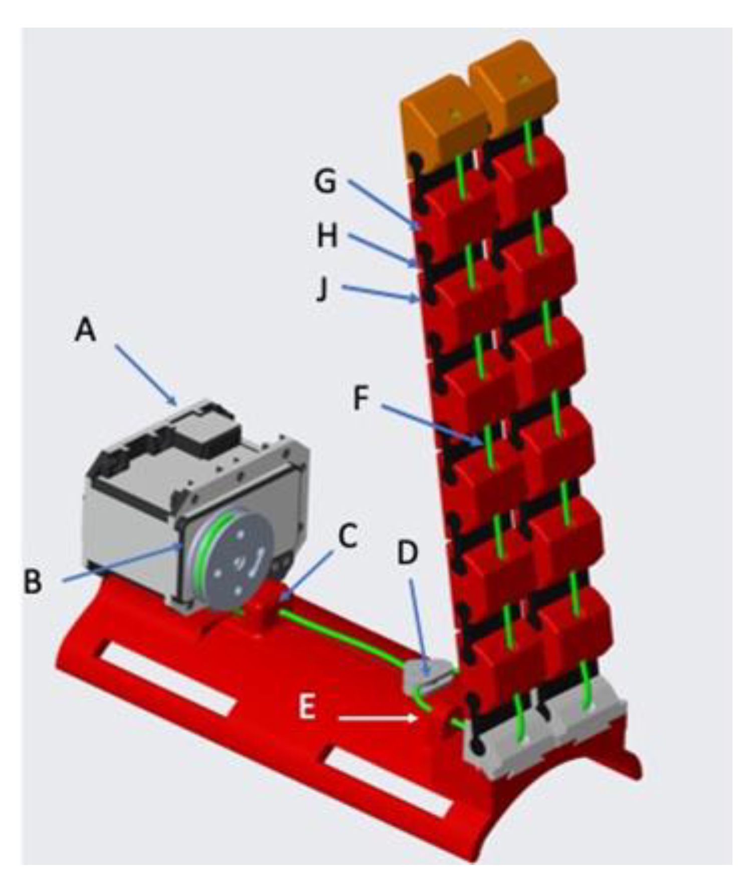
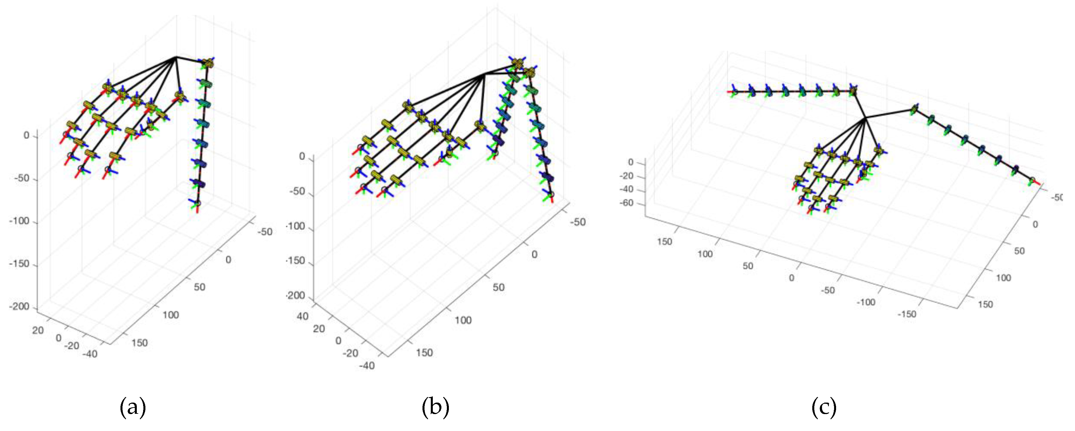
In this paper, the main criteria that were followed to design a double robotic extra finger for compensating and augmenting human hand abilities (Figure 1) are described. Differently from previous works [19,21], all the mechanical components of the fingers were designed in a parametric way, to further exploit the modularity of the device and adapt it to different users and applications. A double wearable robotic extra finger was preliminarily introduced in [29], however, in that device both fingers were actuated with the same motor, using a single Y-shaped tendon that constrained fingers’ motions. This solution was an improvement with respect to a single finger, as it allowed to increase the grasping quality in terms of number of contacts, stability, and grasp stiffness. However, the wearable robot introduced in [29] was not able to adapt to grasp objects with irregular shapes or multiple objects, due to the coupling between fingers generated by the single tendon. The problem can be solved by inserting a differential system between the actuator and the fingers, allowing to decouple their motions. In this paper, we analyze the requirements and main design aspects of the differential mechanism that is necessary to guarantee the proper and decoupled closure movement of each of the two fingers.
The device that is described in the following sections consists of two main parts: the support base and the mobile part, composed of two modular robotic fingers actuated by means of two tendons and a single motor. The end edge of each tendon is fixed on the distal module of the finger, while the opposite side is fastened to an element sliding inside the differential box. Fingers are composed by rigid phalanges connected by compliant interphalangeal joints, that can be approximated as simple 1-DoF revolute joints. When the motor actuates the differential by pulling the sliding element, both tendons flex the fingers, that reach a configuration that is suitable for grasping objects (closed configuration, Figure 1b), while when the torque of the motor is released, the passive elastic elements in the joints restore the fingers to their initial extended configuration (reference open configuration, Figure 1a).
The paper is organized as follows. After an overview of the finger structure (Section 2), a detailed mechanical analysis of the device is given in Section 3 and a first prototype is described in Section 4. Section 5 and Section 6 draw the conclusions of the paper, summarizing envisaged applications of the proposed wearable robotic device.

2. Device Overview

Figure 1 shows the prototype of the double robotic extra finger presented in this work, constituted by two fingers. Each finger has 7 modules, each of which has a part that can be approximately considered rigid (white phalanges in Figure 1) and a part that is passively deformable (black interphalangeal joints in Figure 1). Finger orientation with respect to the fixed support can be manually adapted by the user according to the specific task (see the video S1 in Supplementary Materials).
Rigid elements of the finger can be created with standard Fused Deposition Modelling (FDM) techniques and materials, as for instance Acrylonitrile Butadiene Styrene (ABS) or Polylactic Acid (PLA). For the deformable passive interphalangeal elements, a material that can undergo high deformations when subject to external forces is needed: for these elements, we employed Thermoplastic Polyurethane (TPU) [30], a plastic material that has this desirable mechanical property and can be also manufactured with standard FDM techniques. Furthermore, by changing some manufacturing parameters, as for instance the infill density percentage or pattern, it is possible to modify mechanical properties of the component. The main elements composing modular fingers, as detailed in Figure 2, are rigid elements (Figure 2a–c) and deformable elements (Figure 2d). Three different rigid elements have been designed for the proximal (Figure 2a), intermediate (Figure 2b), and distal (Figure 2c) phalanges. The structure is modular and solutions with different numbers of phalanges can be easily realized. In this paper, we considered fingers composed of seven modules, since we verified that this value is an acceptable trade off to guarantee wearability and suitable grasp capability of several objects related to activities of daily living (ADL).
Each finger is actuated with a single tendon, connected on one side to the actuation and transmission part, and on the other side to the distal phalanx. When the motor actuation pulls the tendon, fingers close following a movement that depends on passive deformable element stiffness. The next section presents the method followed for choosing the mechanical properties (stiffness) of passive elements in interphalangeal joints to obtain a desired closure motion, and how it was applied to different configurations of single and double extra fingers.
The motor and differential mechanism of the double extra finger are installed in a support fixed on user’s forearm (Figure 1a), the overall encumbrance of the motor, differential, and tendon routing system is 130 × 50 × 40 mm. The size of this support can be customized and modelled according to user’s specific requirements. In particular, in future developments of this work we will use 3D scanner techniques [31,32] to reconstruct user’s forearm geometry and to customize the design of the fixed support.
The motor, fixed at the base of the box, rotates the drive pulley. The first tendon connects the motor pulley to a sliding element. Two secondary tendons connect the pulleys of the sliding element to the fingers and are fixed to their distal phalanges.
The main components of the device are shown in the CAD model represented in Figure 3 and are: A) the actuator, B) the drive pulley, C) the fixed pin necessary to provide a suitable direction to the tendon, D) the sliding element, E) two elements necessary to provide the right directions to tendons connected to the fingers, F) the tendons, the finger modules, constituted by G) a rigid element, H) connected to a compliant element, J) through cylindrical guides.
Assembling and de-assembling fingers to adapt them to specific needs or to substitute some of the components is a task that does not need specific knowledge or skills, even if bi-manual operations are required. If the device is used as a rehabilitation or compensation tool by a patient with upper limb impairments limiting its functionality, this operation can be managed for instance by the physiotherapist, a family member, a collaborator, etc. Referring to the elements sketched in Figure 3, the needed operations are: i) disconnect the tendon (F) of the finger that needs to be adapted; ii) de-assemble and re-assemble rigid/flexible elements (G,H) of the finger according to the new configuration (flexible joint passive elements can be connected/disconnected to the rigid links by sliding them along the cylindrical guides in the rigid links (J)); iii) if the number of phalanges has been modified, also tendon length needs to be adapted; iv) re-connect the tendon to the distal phalanx and to the differential sliding element, passing through the rigid links.

3. Analysis

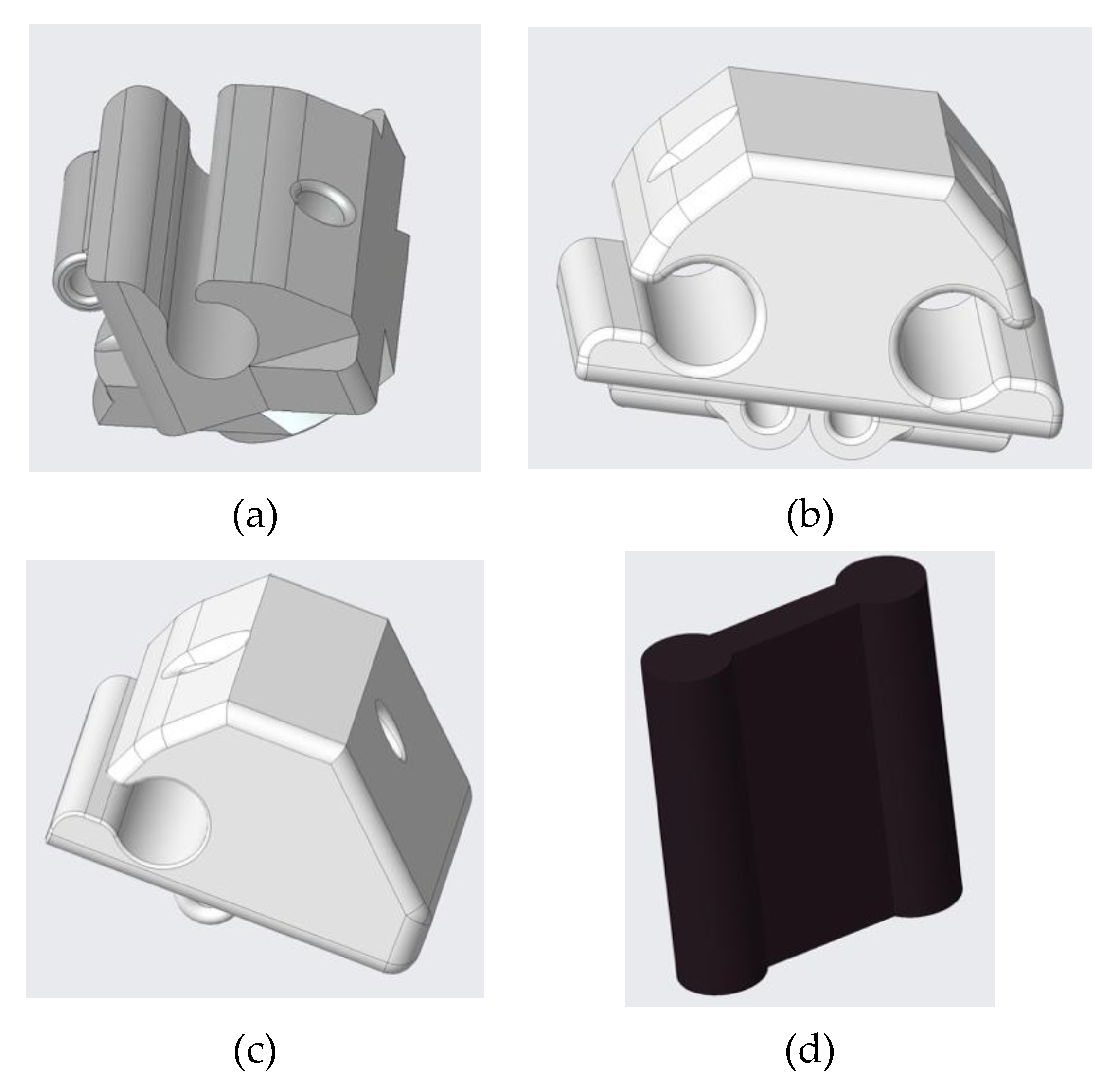
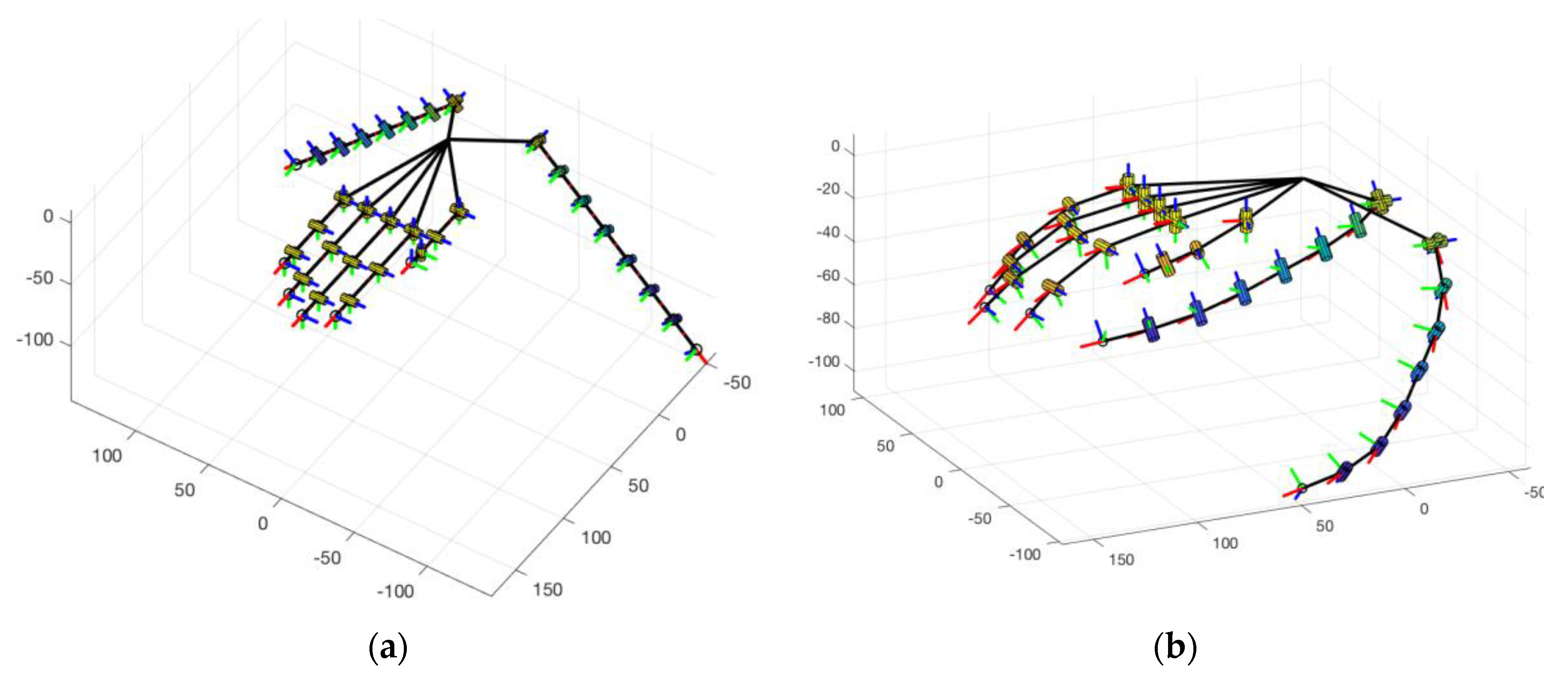
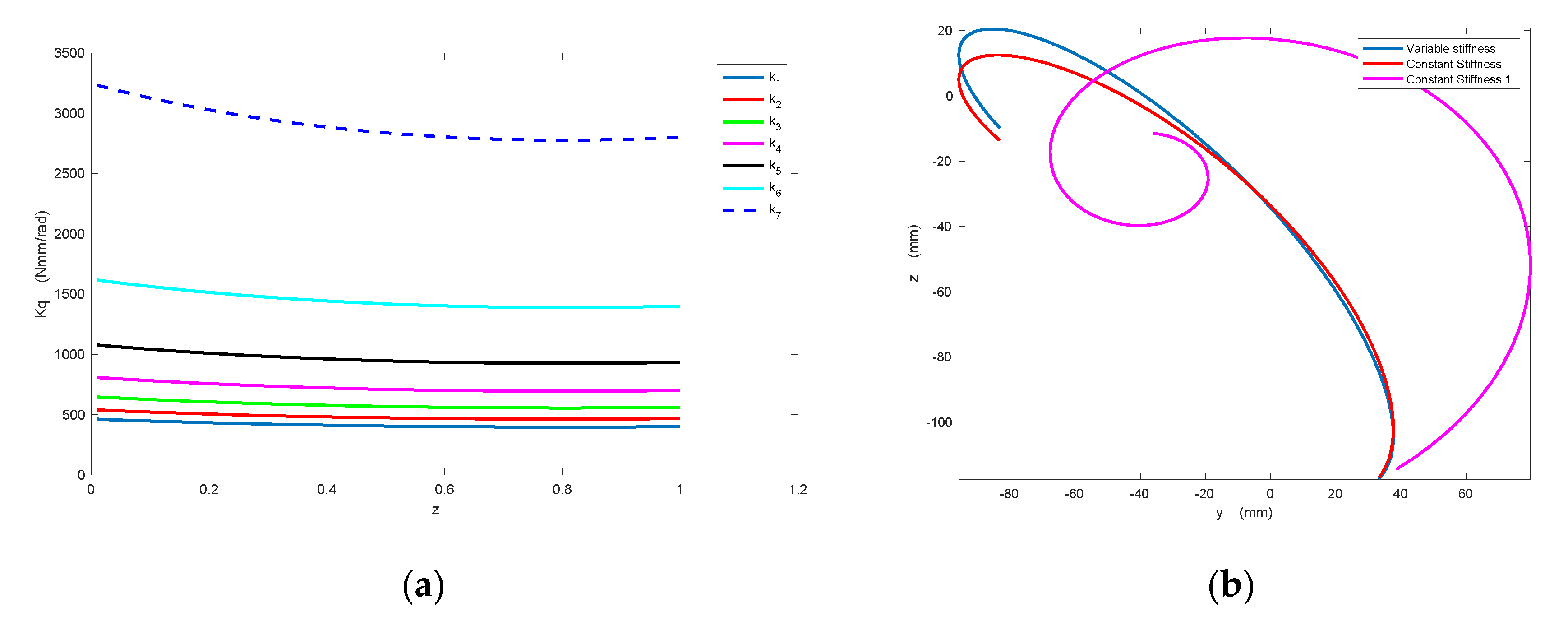
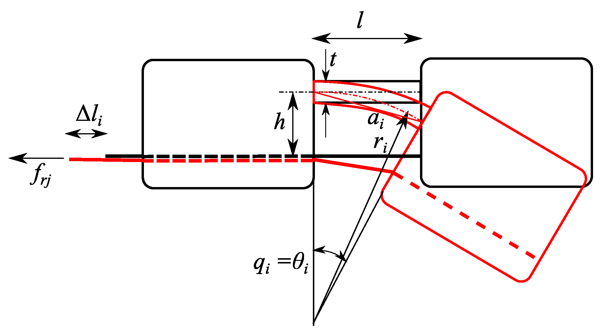
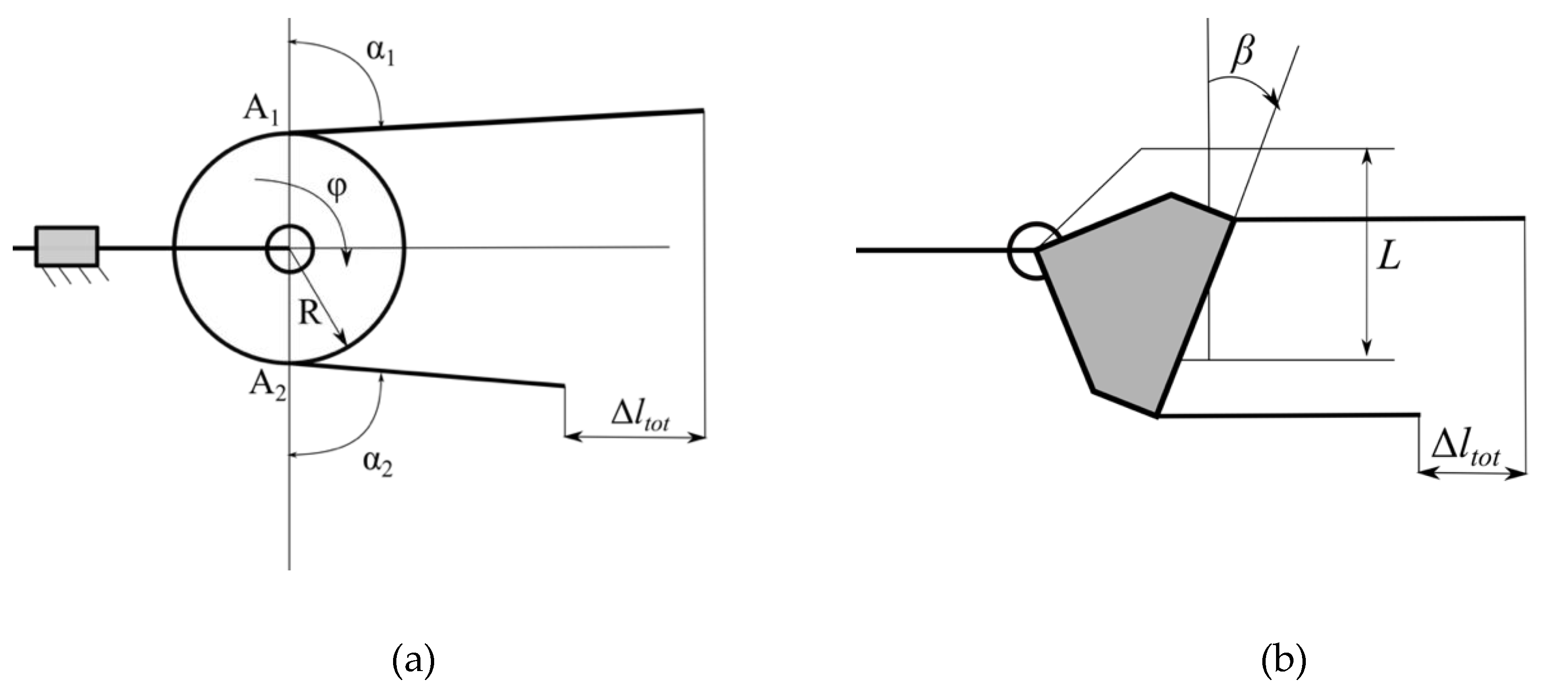
3.1. Design of Finger Passive Elements

As introduced in the previous section, each finger has a single tendon and then, when actuated, can follow only one predefined closure motion. The characteristics of closure motion depend on both geometrical properties of finger components and on the stiffness of the passive element in the interphalangeal joints. When a pulling force is applied to the tendon, stiffer joints will bend less than softer ones. By properly regulating the stiffness of each of the passive elements, it is therefore possible to shape the closure motion. As previously introduced, the modular structure of the finger allows to easily add, remove, or substitute the passive interphalangeal elements, to adapt the finger to different applications.
The first step consists of choosing the closure motion that has to be followed by the extra finger.
In this paper, we focus on a double extra finger device, however the procedure that we present is general and can be adapted to any number of fingers. Let us indicate with r1des(z) = [x1des(z), y1des(z), z1des(z)]T and r2des(z) = [x2des(z), y2des(z), z2des(z)]T two vectors containing the desired trajectories of fingertips, with respect to a reference frame {S0} fixed on fingers’ base. Fingertip coordinates are defined as a function of the variable z, describing the “closure” (z = 0 for completely open fingers, z = 1 for completely closed fingers). For the sake of compactness, let us also collect both finger trajectories in a unique vector [rdes (z)] = [[r1des(z)]T, [r2des(z)]T]T.
To let the extra fingers be able to grasp a wide range of objects, cooperating with the human hand, it is important to choose the most suitable finger closure movement. Different methods can be used to define the desired trajectories rdes(z). In the simulations presented in the following we adopt the procedure based on bio-artificial synergies proposed in [33]. The concept of bio-artificial synergies was introduced in [34] to control wearable extra fingers. Synergies were derived, similarly to [35], by performing the Principal Component Analysis (PCA) on a set of grasps performed by the human hand augmented by two robotic extra fingers. In this paper, we exploit the concept of synergies but we could not extract directly the augmented hand synergy as in [34], since the methodology therein proposed was based on the analysis of a dataset of grasps, that is not available in the design phase of the device. Here we extend the idea of mapping human hand synergies introduced for the human hand in [35], based on the definition of a virtual object, that we presented in some previous works. The method to map human hand first postural synergy to robotic extra fingers has been previously introduced in [33] and in [36]. The output of the mapping procedure are the fingertip trajectories that we want to obtain when actuating the robotic extra fingers.
We therefore choose a set of discrete samples for the variable z describing fingers’ closure motion, z = [z1,…, zNs], we indicate with zi, with i = 1,…, Ns the generic sample, so that z1 = 0 and zNs = 1. We indicate with q a vector containing all the rotations of interphalangeal joints and with q 0 its value corresponding to the initial (completely open) configuration. The value of q at the generic configuration zi can be evaluated by means of a standard inverse kinematic procedure, in particular, in this work we adopted an approximated algorithm based on the Jacobian pseudo-inverse, so that:
q i = q i 1 + [ J ( q i 1 ) ] # ( r d e s ( z i ) r d e s ( z i 1 ) )
where J ( q ) represent the Jacobian matrix of the fingers, relating joint rotation time derivatives to fingertip velocities, i.e.,
r ˙ = J ( q ) q ˙
and # indicates its pseudo-inverse, i.e., [ J ] # = [ J ] T ( [ J ] [ J ] T ) 1 .
Indicating with Δ l is a vector collecting the variation of tendon lengths with respect to the initial reference configuration, choosing the closure motion means specifying the relationship:
q = q ( Δ l ) ,
assuming that no external forces, except the tendon force, are applied to the finger elements. In other terms, in this phase we do not consider any contact between finger elements and an object or the environment. For the prototype that has been introduced in the previous section, q is a vector with 14 elements (7 joints per finger), and Δ l is a vector with 2 elements (lengths of the tendons connected to each finger). In general, in an underactuated system, such a relationship cannot be defined, however, in our case, it can be established since in the joints there are passive elastic elements. The evaluation of the relationship in Equation (3) is possible if the stiffness values of the passive elements are known, as detailed in [33].
As we introduced above, in an underactuated mechanism it is not possible to define the relationship introduced in Equation (3), but it is easy to define, by means of simple geometrical considerations, its dual, i.e.,
Δ l = M q .
It is interesting to notice that this relation can be approximated with a linear map, and the elements of matrix M (whose dimension is 2 × 14 for the device introduced in Section 2) depend on finger geometrical properties [15]. By applying the Principle of Virtual Works to the fingers, it is easy to show that:
τ = M T f ,
where τ is a vector collecting joint stiffness values, while f is the tendon force vector. Since in each joint a passive element is present, from the static analysis of the finger, it results that
τ K q ( q q 0 ) = 0 ,
where q 0 indicates the reference joint configurations, i.e., the configuration corresponding to τ = 0 , and K q is the stiffness matrix. K q elements represent the stiffness of passive elements of the interphalangeal joints. Since these elements are realized with a material with a high flexibility, in general to describe its overall compliance, a 6 × 6 matrix should be necessary. However, it is reasonable to neglect the linear terms (normal and shear deformations), while regarding the rotation elements, the bending stiffness with respect to an axis perpendicular to the finger closure plane is much lower than the value evaluated in the lateral direction, and it is also higher than the torsional stiffness. It is therefore reasonable to model the passive element as a single DoF revolute joint, with an equivalent stiffness value k q i . Matrix K q is a diagonal matrix collecting all the k q i values.
Once the desired closure motion rdes(z) is defined, through the inverse kinematics algorithm in Equation (1) is possible to define the corresponding reference values for interphalangeal joint rotations, q r = q r ( Δ l ) , and therefore, from Equations (3)–(6) it is possible to find the stiffness matrix
K q = K q ( q r , q 0 , f ) .
The second step of the procedure consists in the definition of the stiffness value that each passive element of finger joints has to assume so to realize the desired closure motion. For a more detailed description of the procedure, the reader can refer to [33].
In this paper, we report the results obtained by applying this procedure to three different configurations of human hand and extra fingers. For the evaluation, we realized the mathematical models of the hand augmented with the robotic extra fingers using SynGrasp [37], a Matlab toolbox for the simulation of robotic hand grasping and manipulation, that can manage synergy-actuated and more in general underactuated structures. The human hand biologically has 27 DoF, in this study we adopted a model with 20 DoF, similar to the one described in [38], in which we neglected the carpometacarpal (CMC) articulation of index, middle, ring, and little fingers. We choose this simplified model because we could apply to it the quantitative results, in terms of bio-artificial synergies, evaluated in [35] and available in the Hand Corpus repository (https://www.handcorpus.org/) [39].
Figure 4a shows a link-joint representation of the kinematic structure of the hand augmented with two extra fingers, each extra finger is composed of seven modules. Figure 4b shows the augmented hand configuration when the human fingers are actuated according to the first postural synergy evaluated in [35] and the motion of the robotic ones are evaluated with the mapping procedure reported in [36].
According to the procedure that we previously described, stiffness values of the passive elastic interphalangeal elements of robotic fingers depend on the trajectory that is mapped, but also on the structure of the robotic fingers, and on the force applied on the tendons by the motor. Table 1 summarizes stiffness values obtained with extra fingers composed of 7 modules, in the three configurations, shown in Figure 5: single extra finger opposite to human hand palm (Figure 5a), double configuration with two parallel fingers opposite to human hand palm (Figure 5b), double configuration, with two opposite fingers, one close to human thumb and the other one close to the little finger (Figure 5c). This last configuration has been considered in the analysis phase to verify the effect of finger configuration on closure motion and of the corresponding joint stiffness values. As previously introduced, the orientation of the fingers with respect to the hand can be manually regulated by the user to adapt to different objects and tasks. A configuration similar to the one described in Figure 5c is the one described in [20]. Values in Table 1 have been normalized with respect to the stiffness of the proximal joint, in this way it is possible to compare single and double finger configurations. Since the analyzed configurations are symmetric with respect to the hand, for the sake of brevity in double finger configurations the results have been reported only for one of the fingers. As it can be seen, single and double parallel configurations present similar stiffness values, while the double opposite configuration presents some differences.
Figure 6a shows, for one of the fingers of the configuration in Figure 5b, the stiffness values of the passive interphalangeal elements K q , that have been evaluated on the basis of the motion that we imposed on the fingers, represented as a function of the variable z , describing finger closure, that for this type of mapping is also related to synergy actuation [36] ( z = 0 in the reference open configuration, z = 1 when the hand is closed).
It is interesting to notice that:
  • K q values vary for the different joints: their values determine the closure motion of the fingers and are defined on the basis of the mapping procedure proposed in [36] and in [33].
  • K q values vary as a function of hand configuration, however, for the motion that we selected, such a variation is not very high.
To highlight the effect of joint stiffness values in the closure motion of the finger, in Figure 6b we simulated, for one of the robotic extra fingers, the trajectory of the fingertips obtained with the variable stiffness values defined by the previously described procedure, exactly resembling the “ideal” desired trajectory, (blue curve), the one that we obtain if we consider, for each joint, the mean stiffness value (red curve), and the one that we would obtain if all the joints of the finger had the same stiffness value (magenta curve). As it can be seen, the difference between the blue curve and the red one is quite limited, compatible with the precision required for this type of device (few millimeters), so considering a stiffness value different for all the joints, but constant for each joint, does not introduce significant difference between the closure motion that was planned and the one that can be obtained with the underactuated finger. On the other hand, the difference between ideal fingertip trajectory and the one obtained with the same joint stiffness for all the modules (in the simulation we assumed the mean stiffness value among all the joints) is very high.
The third step consists in creating the passive elements so that their stiffness is the one calculated in the previous phase. We analyzed the possibility of tuning finger joint stiffness values by exploiting the potentialities of 3D printing fabrication methods, that are nowadays rapidly improving and offering interesting opportunities. In particular, choosing a material as the Thermoplastic Polyurethane (TPU) for realizing the flexible parts, we can get different stiffness values, while maintaining the same geometric shape, by regulating the percentage of infill density. This parameter affects primarily material density, but also its mechanical properties [30]. As an example, Table 2 summarizes the variation of Young’s modulus E of TPU as a function of the infill percentage density.
In a more general framework, the overall passive stiffness of a generic joint, indicated with k, depends mainly on joint geometry and material structural properties, and, considering a linear elastic behavior, on Young’s modulus E, i.e.,:
k = k(d, E),
where d is a vector containing all the parameters defining joint geometry (e.g., for a parallelepiped joint, its length l, width w and thickness t). Young’s modulus E depends on material parameters and fabrication methods, i.e.,:
E = E(p1, p2, …, pn),
where each value pi indicates one specific material property. In this work, we exploited the dependency of k with respect to infill density percentage to define robotic finger properties. Future developments of this study will consider other manufacturing parameters, as for instance the infill pattern profile, and also composite materials.

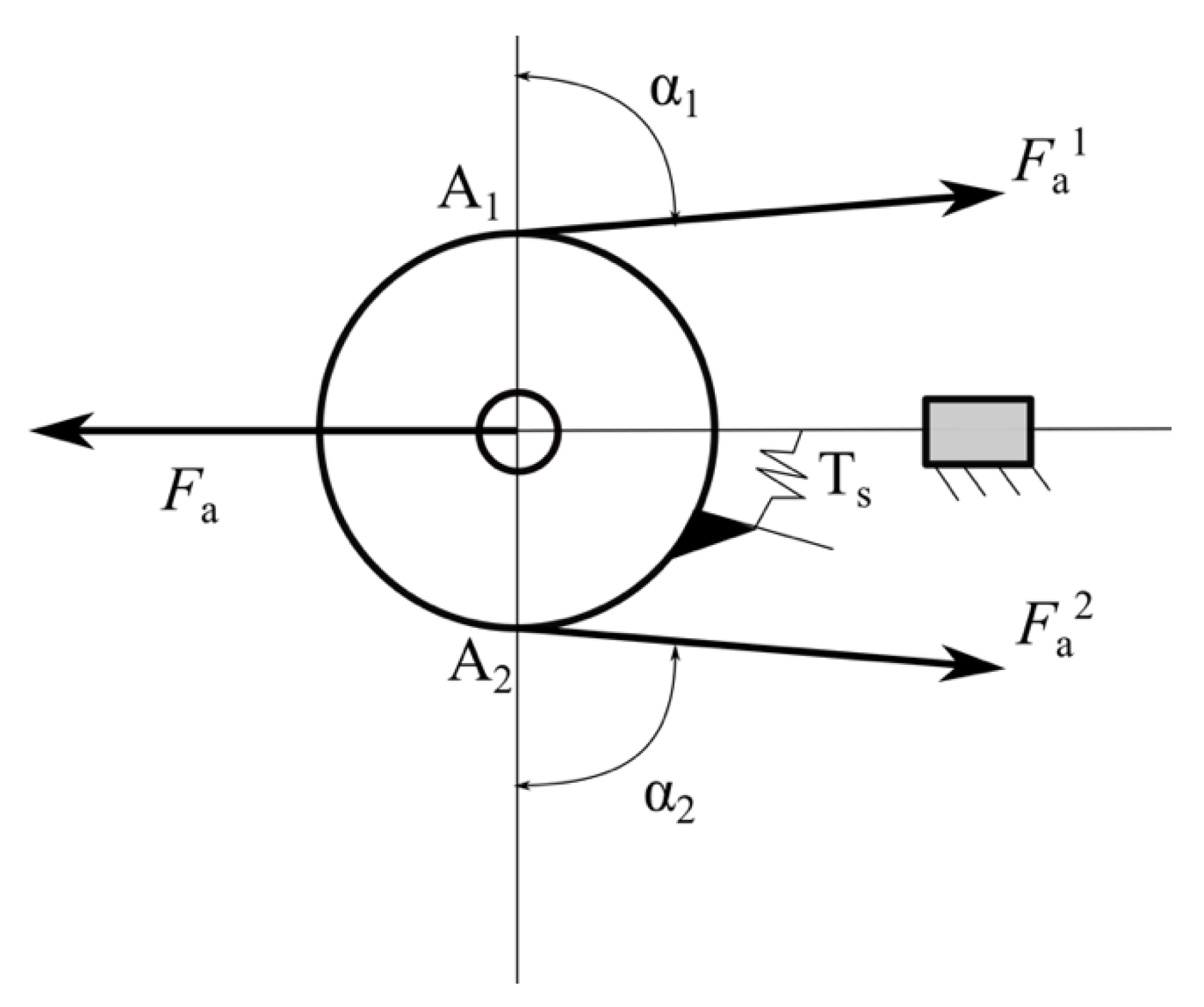
3.2. Mechanical Transmission and Differential Mechanism Analysis

Concerning the differential system, the solution proposed in this paper to actuate a double extra finger device for human hand augmentation is inspired by Dollar’s work on underactuated robotic hands [40], using a moving pulley system; in Figure 7, a simplified and general scheme of this kind of differential is presented [23].
The motivation for this choice is the compactness and excellent adaptability to the human’s forearm dimensions and, since the robotic fingers that are connected through the mechanism use tendons, the mobile pulley mechanism is the most effective system for force transmission. A spring is often used to keep the two outputs in the same reference configuration when the system is not actuated, and the fingers are not externally constrained.
The pulley has 2 DoF: it can translate along a sliding guide (realizing a prismatic joint) and it can rotate around an axis perpendicular to the plane of the figure.
In this scheme, the input force is F a and the output ones are F 1 a and F 2 a . The spring applies a torque T s . In static equilibrium condition the following relationship holds:
F = [ T f   ] t
with
F = [ F 1 a F 2 a ]             t = [ F a T s ]
where the transformation matrix [ T f ] is
[ T f ] = 1 c   [ r sin α 2 r sin α 1 ]
where c is the sum of the distances of A1 and A2 points from the sliding guide (or prismatic joint)
c = r   ( sin α 1 + sin α 2 )
and α 1 and α 2 are the angles shown in Figure 6. If the stiffness of the spring is negligible, Equation (10) can be simplified as:
F 1 a = F 2 a = Fa sin α 1 + sin α 2
An important property of this differential mechanism is that it is isotropic, and thus the two output forces are equal for any value of α 1 and α 2 . The ratio F i a / F a for i = 1,2 is influenced by α 1 and α 2 , and c must be positive for a proper device working.
The distance between the pin and the sliding has to be at least equal to the maximum distance that the pulley has to travel while both the fingers are completely closed from an initial extended configuration. Let us consider one of the fingers and let us indicate with Θ the generic rotation between the x n axis, defined on the distal phalanx of one finger and the reference direction x 0 on the device base. Reference frames are defined so that Θ = 0 in the initial extended configuration, while Θ = Θ c in the configuration corresponding to complete finger closure. Let us indicate with ϑ i the rotation of the i-th joint, so that
Θ c = i = 1 n ϑ i
To obtain the rotation ϑ i the tendon is pulled by the motor and its length variation is indicated with Δ l i (Figure 8). When the joint is rotated, the elastic element bends; indicating with l its length and assuming that after the deformation its profile is circular, its curvature radius can be evaluated as r i = l ϑ i . The corresponding arc cord can be evaluated as:
a i = 2 r i sin ( ϑ i 2 )
and tendon length variation is therefore (Figure 8)
Δ l i = l a i l   ( r i   h ) = l 2 r i   ( r i   h ) r i sin ( ϑ i 2 )
To close the fingers, it is necessary to vary the length of the tendon by Δ l t o t , that can be evaluated as
Δ l t o t = 1 n Δ l i
Assuming l i = 17.3   m m for all the elements, h = 5   m m and Θ c = 2 π we obtain Δ l t o t = 28   m m : this is the maximum length variation of the tendon and corresponds to the maximum displacement of the sliding element. This result is necessary to define the minimum size of the box containing the differential mechanism.
Δ l t o t represents also the maximum difference between fingers’ tendon lengths when the differential is working, for example when one of the fingers is blocked in its straight initial configuration and the other one is free and can complete the closure.
Two possible solutions can be realized (Figure 9): in the first one (Figure 9a) the sliding element of the differential is constrained to move in one fixed direction by means of a prismatic joint, the two tendons are connected in a unique tendon that can slide over the element. In this case at least one pulley is necessary to reduce the friction. In the second solution (Figure 9b), the sliding element is able both to slide and to tilt inside the box, and the output tendons are connected directly to its edges, the differentiation between output motions is possible thanks to the tilting motion of the sliding element.
The first solution allows a more compact implementation; however, it requires that the sliding element is not a rigid body (at least one pulley, connected to the main body of the sliding element through a revolute joint, is needed).
Considering a single pulley, as shown in Figure 9a, indicating with R its radius, when a differential motion Δ l t o t is required, pulley rotation is simply given by
φ = Δ l t o t R
The second solution needs larger components, but simpler from the mechanical and manufacturing point of view. In a preliminary design phase, we analyzed both the solutions, in the following prototyping phase we realized the second solution because it resulted mechanically simpler and more robust. Indicating with L the width of the sliding element, i.e., the distance between the points in which fingers tendons are connected to it and with β its rotation generated by a difference Δ l t o t between the deformation of fingers’ tendons, it is easy to verify that (Figure 9b):
Δ l t o t L = sin β
assuming L = 32   m m , we get β = 64 ° .

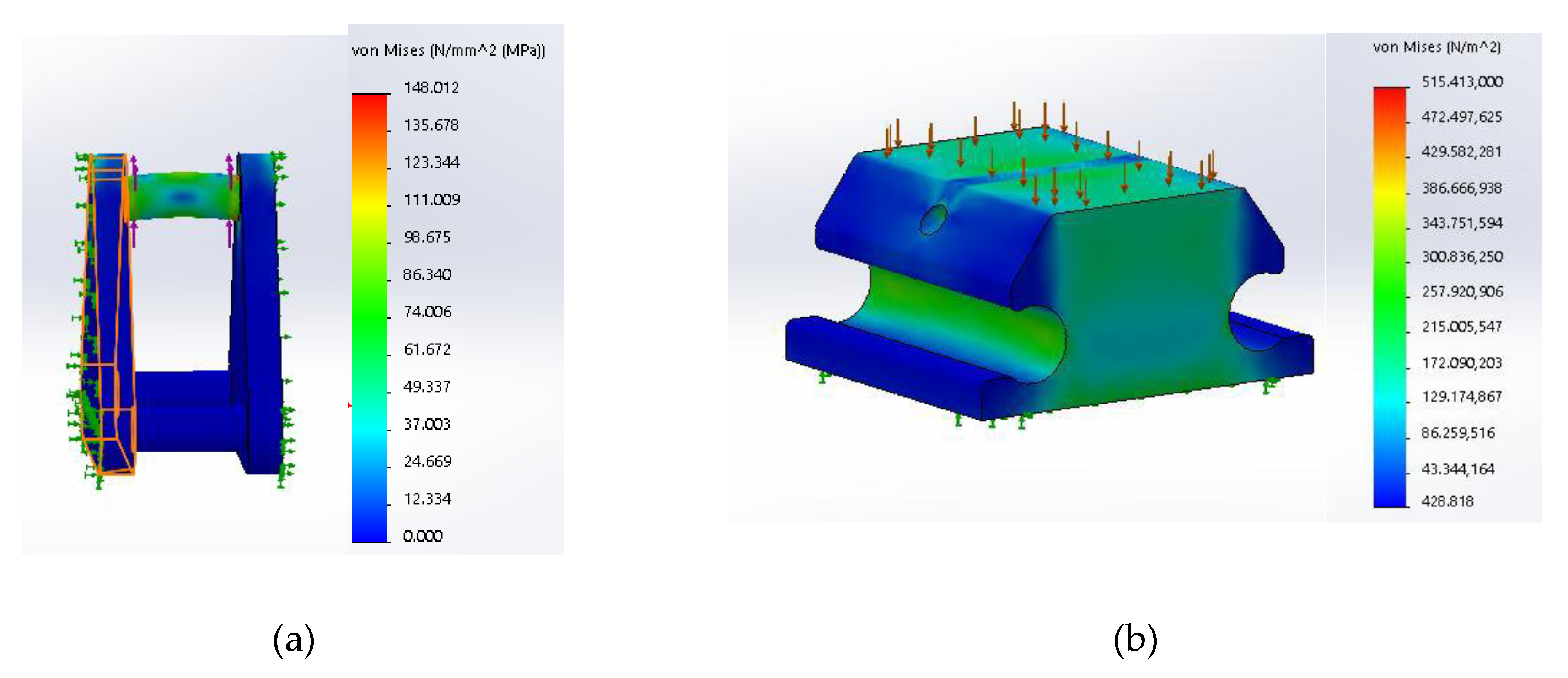
3.3. Structural Analysis of Rigid Elements

For the realization of the prototypes we exploited standard additive manufacturing techniques, that allow to use light materials with quite low price, and to easily adapt the design to specific user’s need. The differential mechanism was designed for a standard 3D printing considering generic Acrylonitrile Butadiene Styrene (ABS) material, that has a limited density, good structural properties, good resistance to heat and impacts [41]. The main mechanical properties of ABS material are summarized in Table 3.
Considering the limited dimensions of the mechanical components and the loads that they have to resist; a static analysis of the most solicited elements was performed testing their resistance by means Finite Element Method (FEM) analysis.

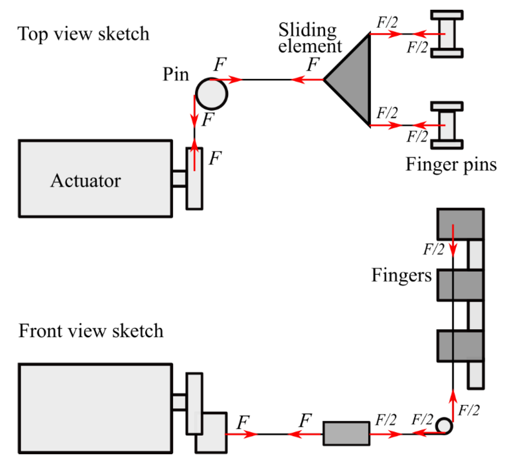
3.3.1. Force Analysis

When the motor applies the maximum torque (we considered a Dynamixel MX-28T—Robotis, South Korea—able to apply a torque of 3.1 Nm @ 12 V), assuming a motor pulley radius of 11 mm, we get an equivalent force on the tendon equal to F = 282 N. In quasi-static conditions the elements of the differential mechanism are subject to the forces sketched in Figure 10.

3.3.2. Stress Analysis Results

Given the previously introduced force distribution, we analyzed stress distribution on the main elements of the finger transmission. The most stressed element results to be the sliding element. The dimensions of the sliding element have been defined based on geometrical considerations summarized in the preceding sections. On the motor side, the central pivot is tied to the tendon connected to the driving pulley, that allows sliding. On the finger side, two tendons are connected to the finger pins. Figure 11a shows Von Mises equivalent stress distribution. It can be noticed that the central pivot is the most stressed part of the sliding element. There are peaks of stress concentration in the edges that are not compatible with a standard ABS material. This drawback can be easily mitigated in the design and prototyping phase by increasing fillet radii. Since this is the most stressed element of the transmission system and it is not physically connected to other components, we can also consider different types of material to realize it, as for instance ABS reinforced with carbon or metal fiber [30], or metal alloys.
Rigid elements of finger phalanges have a quite robust shape; in Figure 11b we report as an example the results of a FEM static simulation in which we applied a compressive loading of 40 N. As it can be seen, the overall stress level is low.

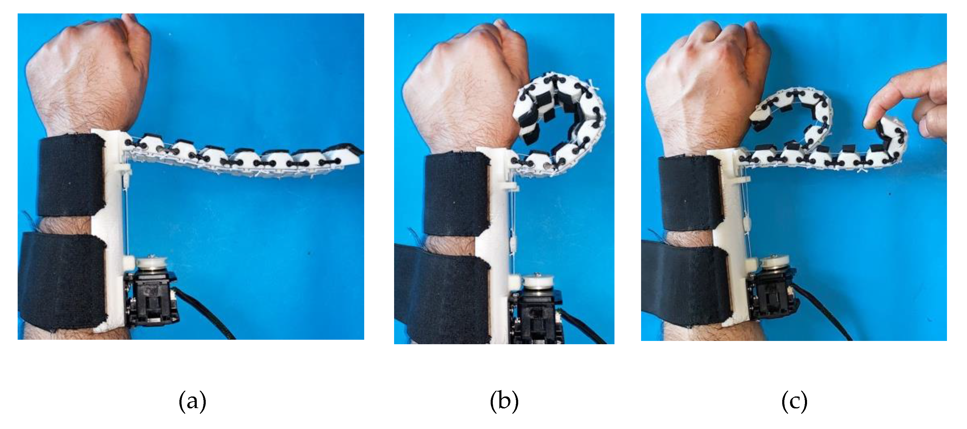
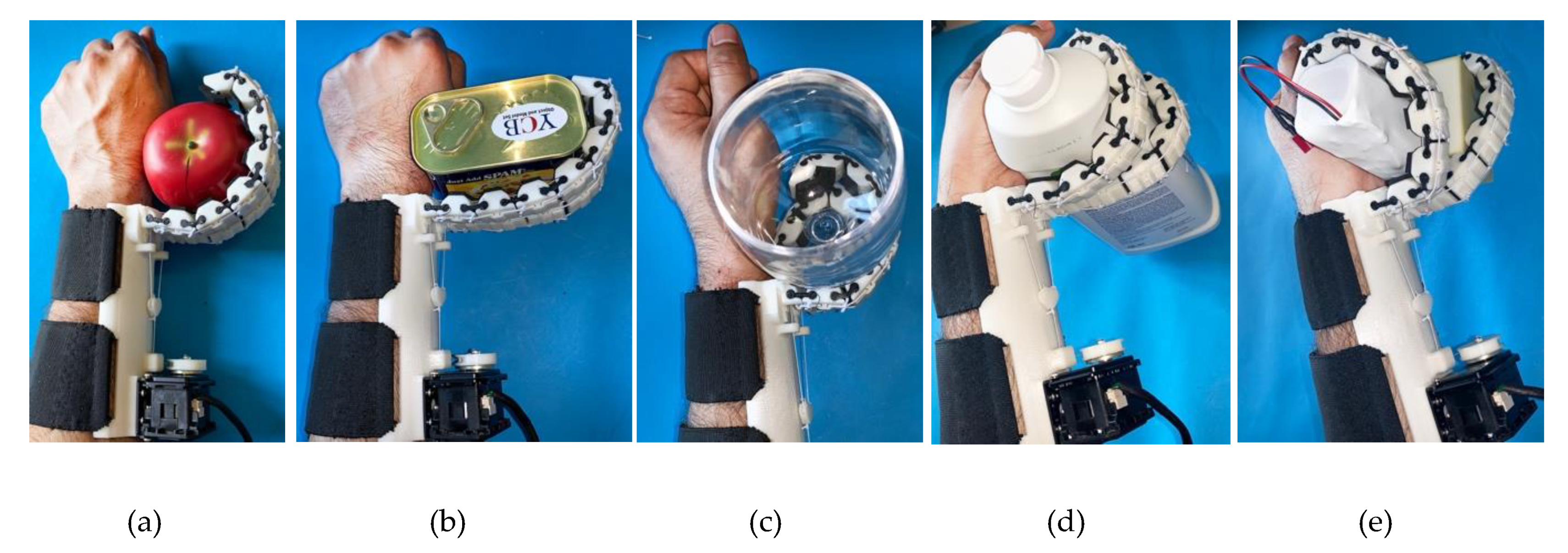
4. Prototype Presentation

A simplified demonstrative prototype of the proposed double finger device is shown in Figure 1. As previously explained, the device has been designed to be wearable, robust and compliant to adapt to different object shapes. The device consists of two main parts, a support base and two flexible fingers. The flexible fingers have a modular structure, each module is composed of a 3D printed ABS polymeric part that acts as a rigid link and a TPU part that realizes the flexible joint. Soft rubber pads are glued to the rigid links to increase the friction at possible contact areas. The modules are assembled by sliding the flexible part in the rigid one (Figure 2). The support base of the finger is realized in ABS. It contains the actuator, the differential and two elastic bands that allows the user to wear it on the forearm.
The actuator moves the fingers through a tendon connected to the sliding element that constitute the differential. A hole in the rigid links allows the passage of a cable (Dyneema polyethylene fiber, Japan) which is used to realize the tendon driven actuation. The tendon wires run through the fingers and are attached on one side to the fingertips and on the other to the sliding element. Another tendon connects the sliding element to a pulley connected to the actuator. The actuator used, as previously introduced, is a Dynamixel servo AX12-A (Robotis, Korea) [42]. Principal details on the motor and device features are reported in Table 4. We use ArbotiX-M Robocontroller to drive the Dynamixel motor [43]. This control solution for Dynamixel motors incorporates an AVR microcontroller, Xbee wireless radio and the motor driver.
Interfaces for controlling wearable extra fingers have been developed within this research activity, for the sake of brevity we report in this paper a brief summary on the main solutions. The key aspects that were considered in the design of these interfaces were reliability, easiness and intuitiveness of use also by untrained people, accessibility from people with partial upper limb impairments, and limited costs. Different wearable interfaces have been developed to control wearable extra fingers, and also to let the user feel a haptic stimulus communicating a specific state of the robotic extra finger. An interesting example control device is the eCap, an Electromyography (EMG) interface embedded in a cap: wearing the eCap the user can control the flexion/extension of the robotic finger by contracting the frontalis muscle by moving his or her eyebrows upwards. The motion of the robotic extra finger is controlled using a trigger signal based finite state machine (FSM), as detailed in [44].
Another possible interface is the so-called hRing, a ring that can be worn by the user on the healthy hand, provided by buttons for opening/closing the wearable extra fingers and with a vibrating motor providing a haptic cutaneous feedback stimulus to the user’s healthy hand [44].
For control design, a simple and robust solution has been implemented. Device actuator is position controlled, a linearly increasing/decreasing reference position value is sent to the actuator according to inputs provided by the users through the interface or state variations, as detailed in the following. The prototype proposed in this paper has not position/force sensors on the fingers, control system behavior is developed on the basis of motor internal sensors only. In particular, it is possible to use the internal controller available in the servomotor to control the exerted torque. This controller uses a torque estimation based on the measured load current. The torque control may be used to limit the grasping force on the objects or to check whether an object is firmly grasped. This information can be haptically communicated to the user as a vibration signal if the hRing interface is employed. Examples on the use of torque control can be found in [45].
Through the interfaces, the users control the motion/stop of the finger with a specific command on the control interface (e.g., a single muscle contraction with the eCap, the activation of one of the two buttons on the hRing). Once the finger is stopped, another input (e.g., two contractions of the muscle, the activation of the second button in the hRing) switches the direction of motion from flexion to extension and vice versa. A software defined trigger stops the actuator’s motion once the object is considered as grasped, to avoid a torque overloading situation. Object grasping is detected by continuous monitoring of the actuator’s shaft position and the exerted torque.
In particular, when flexion command is selected, a desired position for the servomotor ϑ d e s , corresponding to a configuration in which, both the extra fingers are completely flexed. For instance, for the device previously introduced, with 7 modules for both the fingers, from Equation (16), it results that the overall displacement of the main tendon, needed to fully close the fingers, is Δ l t o t = 28   m m . Considering that the pulley connected to the servomotor is r m = 11 mm, the corresponding rotation for the motor is   ϑ d e s = 150°. The desired value of the angular velocity ( ω d e s = 33.3 °/s) is also set in the position control system. When extension/release command is selected by the user, the desired position is set to 0°, which results in the finger completely extended, with the same desired velocity.
The lack of precision in sensing and control is compensated by the adaptability properties of the device, inherently provided by joint passive compliance and by the differential mechanism that decouples fingers’ closure motions [7]. More complex control strategies were tested in some preliminary works [18], but they were suitable for fully actuated devices and needed sophisticated and expensive sensors for human hand tracking, for example a Cyberglove [46]. Although these works provided us interesting results, we recognized that they were not suited for the application outside research laboratories, with patients dealing with everyday activities.
Figure 12 shows some examples of grasps realized with the wearable device. As it can be seen, even if the device is actuated by only one motor, the underactuated structure of the fingers and the differential system allow the device to adapt to different object shapes, realizing stable grasps of large objects, having a weight up to 2 kg, and also to grasp multiple objects. Device performance, in terms of payload (e.g., maximum weight of the grasped object, maximum fingertip force, maximum and minimum diameter of the grasped object), are summarized in Table 5. It is worth to notice that some of the grasps reported in Figure 12 would be weak or impossible with a single finger device (e.g., Figure 12c–e) or with a double extra finger without differential mechanism as the one presented in [29] (Figure 12c,e). Other grasp examples have been presented in the video S1 in Supplementary Materials.

5. Discussion on Potential Applications, Links

Wearable robots present interesting design challenges, since they are expected to closely work and collaborate with users, in an unstructured and dynamical environment. Wearable devices require additional design requirements, concerning weight, adaptability to user’s body specificity, safety, robustness, and easiness of use. A rather new research branch in wearable robotics deals with human body augmentation. In this work, we analyzed a device for human hand augmentation, focusing on its mechanical design, rather than on its control and interfacing with the human, that was the focus of other works [44]. Human hand augmentation by means of robotic extra fingers represents an interesting research topic, involving engineering as well as ethical and philosophical challenges.
With respect to other solutions available in the literature [16,17,20], the device that we propose presents the following features:
  • Actuation: while other devices available in the literature have a rigid and fully actuated structures, in the device presented in this work only one motor is necessary to actuate both the single and the double finger configurations. This feature limits the weight, complexity of the device, and improve its wearability and user comfort.
  • Modularity: as discussed in Section 2, the structure of the fingers is modular at the phalanx level, the same modules can be used both for the single and double finger configurations. The device can be easily adapted to user’s specific needs and features. For instance, a smaller hand would need a device with smaller dimensions that can be easily obtained realizing fingers with less modules.
  • Robustness, safety for the user: in this type of devices the fingers are the elements more sensitive to unexpected contacts with the environment and shocks. Passive elements present in the interphalangeal joints of the fingers are realized by TPU, a material that presents high resistance to impacts and elongation at break. As a result, the fingers are quite robust and can resist to uncertainties and unpredictable impacts that may occur during activities of daily living (ADL). At the same time, their compliance limits the risks for the user and for other people.
  • Adaptability: the compliant structure provided by deformable elements in interphalangeal joints and the differential mechanism allow the device to automatically adapt to different objects with different shapes and dimensions, without the need of specific sensors on the fingers and complex control strategies.
  • Costs: the simple but versatile mechanical structure, the choice of widely diffused and affordable manufacturing technologies and materials, and the modularity, lead to a cost of the device that is quite limited.
We believe that the most impactful application of the device presented in this paper is rehabilitation and assistance of patients with upper limb impairments, for example after a stroke [47]. Stroke is a brain attack, affecting 17 million people worldwide each year, it is the second most common cause of death and a leading cause of adult physical disability (http://strokeeurope.eu/). Impairment of the hand, and in particular of its grasping and dexterous manipulation capabilities is one of the common deficits after a stroke. Approximately 60% of stroke survivors suffer from some form of sensorimotor impairment associated with their hand. Rehabilitation processes could take advantage from robotic devices, that can be used to practice intense movement training at home. Supernumerary fingers enable patients to execute grasp and release exercises and practice intensively using repetitive movements.
Different configurations for the robotic extra fingers, with one or two fingers, have been realized following the principles that we summarized in the previous sections and are now available for testing. Double configurations allow more stable grasps and the possibility of carrying heavier loads. In addition to rehabilitation purposes, supernumerary robotic fingers can increase patients’ grasping capabilities, especially in objects manipulation, thereby improving their independence in ADL, and simultaneously decreasing the need of compensatory unnatural motor strategies for solving everyday tasks. Supernumerary limbs will provide novel opportunities to recover missing abilities, resulting in improvements of patients’ quality of life.
The devices were tested with chronic stroke patients through qualitative experiments based on ADL and preliminary results are widely discussed in [19,45]. The goal of the tests was to evaluate how quickly and easily the patients could learn to use the device in ADL. Different applications were considered (e.g., kitchen scenario, consisting in preparing breakfast and lunch, some tools activities, using the extra finger as an active hook, etc.). The initial tests gave encouraging results; users could complete the tasks reducing the time and with good success rates.

6. Conclusions

In this paper, we summarized the work regarding the mechanical design of supernumerary robotic fingers that can be used for augmenting and compensating the human hand manipulation abilities. Wearability requirements set constraints on the hardware structure, that needs to be light, robust and safe. We focused in particular on the analysis of the transmission system that is needed when more than one finger is employed and all the fingers are actuated with the same motor. We are still optimizing the design, by further studying the possibility of exploiting additive manufacturing technology to change the stiffness of the finger’s joints. We are working on integrating the extra fingers with other devices, as for instance assistive tools for wrist motion and arm support, investigating the possibility of using our devices in patients affected by other neurological diseases affecting hand grasping.

Supplementary Materials

The following are available online at https://0-www-mdpi-com.brum.beds.ac.uk/2218-6581/8/4/102/s1, Video S1: Design of multiple wearable extra fingers for human hand augmentation.

Author Contributions

Conceptualization, G.S.; Investigation, M.M., Z.I. and M.C.V.; Methodology, M.M., M.C.V., M.P., D.P. and G.S.; Supervision, M.P. and D.P.

Funding

This research was funded by the European Union EU H2020 projects under grant n. 780073 of the project “INBOTS Inclusive Robotics for a Better Society.

Conflicts of Interest

The authors declare no conflict of interest.

References

  1. Mason, M.T.; Salisbury, J.K. Robots Hands and the Mechanics of Manipulation; MIT Press: Cambridge, MA, USA, 1985; ISBN 9780262132053. [Google Scholar]
  2. Carbone, G. Grasping in Robotics; Springer: Dordertch, The Netherlands, 2013. [Google Scholar] [CrossRef]
  3. Fukaya, N.; Toyama, S.; Asfour, T.; Dillmann, R. Design of the TUAT/Karlsruhe humanoid hand. In Proceedings of the IEEE/RSJ International Conference on Intelligent Robots and Systems, Takamatsu, Japan, 31 October–5 November 2000; pp. 1754–1759. [Google Scholar] [CrossRef]
  4. Butterfass, J.; Grebenstein, M.; Liu, H.; Hirzinger, G. DLR-hand II: Next generation of a dexterous robot hand. In Proceedings of the IEEE International Conference on Robotics and Automation, Seoul, Korea, 21–26 May 2001; pp. 109–114. [Google Scholar] [CrossRef] [Green Version]
  5. Martin, E.; Desbiens, A.L.; Laliberté, O.T.; Gosselin, C. SARAH hand used for space operation on STVF robot. In Proceedings of the Intelligent Manipulation and Grasping, Genoa, Italy, 1–2 July 2004; pp. 279–284. [Google Scholar]
  6. Roccella, S.; Carrozza, M.C.; Cappiello, G.; Dario, P.; Cabibihan, J.J.; Zecca, M.; Hiwa, H.; Itoh, K.; Matsumoto, M.; Takanishi, A. Design, fabrication and preliminary results of a novel anthropomorphic hand for humanoid robotics: RCH-1. In Proceedings of the IEEE/RSJInternational Conference on Intelligent Robots and Systems, Sendai, Japan, 28 September–2 October 2004; pp. 266–271, ISBN 0780384636. [Google Scholar]
  7. Dechev, N.; Cleghorn, W.L.; Nauman, S. Multiple finger, passive adaptive grasp prosthetic hand. Mech. Mach. Theory 1999, 36, 1157–1173. [Google Scholar] [CrossRef]
  8. Raparelli, T.; Mattiazzo, G.; Mauro, S.; Velardocchia, M. Design and development of a Pneumatic anthropomorphic hand. J. Robot. Syst. 2000, 17, 1–15. [Google Scholar] [CrossRef]
  9. Maffiodo, D.; Raparelli, T. Three-Fingered Gripper with Flexure Hinges Actuated by Shape Memory Alloy Wires. Int. J. Autom. Technol. 2017, 11, 355–360. [Google Scholar] [CrossRef]
  10. Niola, V.; Penta, F.; Rossi, C.; Savino, S. An underactuated mechanical hand: Theoretical studies and prototyping. Int. J. Mech. Control 2015, 16, 11–19. [Google Scholar]
  11. Cosenza, C.; Niola, V.; Savino, S. Analytical study for the capability implementation of an underactuated three-finger hand. Mech. Mach. Sci. 2019, 65, 161–168. [Google Scholar] [CrossRef]
  12. Niola, V.; Rossi, C.; Savino, S.; Timpone, F. Study of an underactuated mechanical finger driven by tendons. Int. J. Autom. Technol. 2017, 11, 344–354. [Google Scholar] [CrossRef]
  13. Maffiodo, D.; Raparelli, T. Comparison among different modular SMA actuated flexible fingers. Mech. Mach. Sci. 2019, 68, 324–331. [Google Scholar] [CrossRef]
  14. Carbone, G.; Rossi, C.; Savino, S. Performance comparison between FEDERICA hand and LARM hand. Int. J. Adv. Robot. Syst. 2015, 12, 90. [Google Scholar] [CrossRef]
  15. Kobayashi, H.; Hyodo, K.; Ogane, D. On tendon-driven robotic mechanisms with redundant tendons. Int. J. Robot. Res. 1998, 17, 561–571. [Google Scholar] [CrossRef]
  16. Parietti, F.; Asada, H. Supernumerary robotic limbs for human body support. IEEE Trans. Robot. 2016, 32, 301–311. [Google Scholar] [CrossRef]
  17. Wu, F.Y.; Asada, H.H. “Hold-and-manipulate” with a single hand being assisted by wearable extra fingers. In Proceedings of the 2015 IEEE International Conference on Robotics and Automation (ICRA), Seattle, WA, USA, 26–30 May 2015. [Google Scholar]
  18. Prattichizzo, D.; Malvezzi, M.; Hussain, I.; Salvietti, G. The sixth-finger: A modular extra-finger to enhance human hand capabilities. In Proceedings of the 23rd IEEE International Symposium on Robot and Human Interactive Communication, Edinburgh, UK, 25–29 August 2014; pp. 993–998. [Google Scholar] [CrossRef]
  19. Hussain, I.; Salvietti, G.; Spagnoletti, G.; Prattichizzo, D. The soft-sixthfinger: A wearable emg controlled robotic extra-finger for grasp compensation in chronic stroke patients. IEEE Robot. Autom. Lett. 2016, 1, 1000–1006. [Google Scholar] [CrossRef] [Green Version]
  20. Hu, Y.; Leigh, S.W.; Maes, P. Hand Development Kit: Soft Robotic Fingers as Prosthetic Augmentation of the Hand. In Proceedings of the Adjunct Publication of the 30th Annual ACM Symposium on User Interface Software and Technology, Québec City, QC, Canada, 22–25 October 2017. [Google Scholar]
  21. Hussain, I.; Salvietti, G.; Spagnoletti, G.; Malvezzi, M.; Cioncoloni, D.; Rossi, S.; Prattichizzo, D. A soft supernumerary robotic finger and mobile arm support for grasping compensation and hemiparetic upper limb rehabilitation. Robot. Auton. Syst. 2017, 93, 1–12. [Google Scholar] [CrossRef]
  22. Laliberté, T.; Gosselin, C.M. Underactuation in space robotic hands. In Proceedings of the International Symposium on Artificial Intelligence, Robotics and Automation in Space, Montréal, QC, Canada, 18–22 June 2001. [Google Scholar]
  23. Birglen, L.; Gosselin, C.M. Force Analysis of Connected Differential Mechanisms: Application to Grasping. Int. J. Robot. Res. 2006, 25, 1033–1046. [Google Scholar] [CrossRef]
  24. Zappatore, G.A.; Reina, G.; Messina, A. Analysis of a highly underactuated robotic hand. Int. J. Mech. Control 2017, 18, 17–24. [Google Scholar]
  25. Birglen, L.; Gosselin, C.M. On the force capability of underactuated fingers. In Proceedings of the IEEE International Conference on Robotics and Automation, Taipei, Taiwan, 14–19 September 2003; pp. 1139–1145. [Google Scholar] [CrossRef]
  26. Massa, B.; Roccella, S.; Carrozza, M.C.; Dario, P. Design and development of an underactuated prosthetic hand. In Proceedings of the 2002 IEEE International Conference on Robotics and Automation, Washington, DC, USA, 11–15 May 2002; pp. 3374–3379. [Google Scholar] [CrossRef]
  27. Baril, M.; Laliberté, T.; Gosselin, C.; Routhier, F. On the design of a mechanically programmable underactuated anthropomorphic prosthetic gripper. J. Mech. Des. 2013, 135, 121008. [Google Scholar] [CrossRef]
  28. Kontoudis, G.P.; Liarokapis, M.V.; Zisimatos, A.G.; Mavrogiannis, C.I.; Kyriakopoulos, K.J. Open-source, anthropomorphic, underactuated robot hands with a selectively lockable differential mechanism: Towards affordable prostheses. In Proceedings of the 2015 IEEE/RSJ International Conference on Intelligent Robots and Systems (IROS), Hamburg, Germany, 28 September–2 October 2015; pp. 5857–5862. [Google Scholar]
  29. Hussain, I.; Spagnoletti, G.; Salvietti, G.; Prattichizzo, D. Toward wearable supernumerary robotic fingers to compensate missing grasping abilities in hemiparetic upper limb. Int. J. Robot. Res. 2017, 36, 1414–1436. [Google Scholar] [CrossRef]
  30. Ning, F.; Cong, W.; Qiu, J.; Wei, J.; Wang, S. Additive manufacturing of carbon fiber reinforced thermoplastic composites using fused deposition modeling. Compos. Part B Eng. 2015, 80, 369–378. [Google Scholar] [CrossRef]
  31. Valigi, M.C.; Logozzo, S.; Canella, G. A new automated 2 DOFs 3D desktop optical scanner. In Mechanisms and Machine Science; Springer: Berlin, Germany, 2017; Volume 47, pp. 231–238. [Google Scholar] [CrossRef]
  32. Valigi, M.C.; Logozzo, S.; Canella, G. A robotic 3D vision system for automatic cranial prostheses inspection. Mech. Mach. Sci. 2018, 49, 328–335. [Google Scholar] [CrossRef]
  33. Salvietti, G.; Hussain, I.; Malvezzi, M.; Prattichizzo, D. Design of the passive joints of underactuated modular soft hands for fingertip trajectory tracking. IEEE Robot. Autom. Lett. 2017, 2, 2008–2015. [Google Scholar] [CrossRef] [Green Version]
  34. Wu, F.Y.; Asada, H. Bio-Artificial Synergies for Grasp Posture Control of Supernumerary Robotic Fingers; MIT Press: Cambridge, MA, USA, 2014. [Google Scholar]
  35. Santello, M.; Flanders, M.; Soechting, J.F. Postural Hand Synergies for Tool Use. J. Neurosci. 1998, 18, 10105–10115. [Google Scholar] [CrossRef]
  36. Malvezzi, M.; Valigi, M.C.; Salvietti, G.; Iqbal, Z.; Hussain, I.; Prattichizzo, D. Design criteria for wearable robotic extra–fingers with underactuated modular structure. Mech. Mach. Sci. 2019, 68, 509–517. [Google Scholar] [CrossRef]
  37. Malvezzi, M.; Gioioso, G.; Salvietti, G.; Prattichizzo, D. SynGrasp: A Matlab Toolbox for Underactuated and Compliant Hands. IEEE Robot. Autom. Mag. 2015, 22, 52–68. [Google Scholar] [CrossRef]
  38. Cobos, S.; Ferre, M.; Uran, M.S.; Ortego, J.; Pena, C. Efficient human hand kinematics for manipulation tasks. In Proceedings of the 2008 IEEE/RSJ International Conference on Intelligent Robots and Systems, Nice, France, 22–26 September 2008; pp. 2246–2251. [Google Scholar]
  39. Bianchi, M.; Liarokapis, M.V. HandCorpus, a new open-access repository for sharing experimental data and results on human and artificial hands. In Proceedings of the IEEE World Haptics Conference (WHC), Daejeon, Korea, 14–17 April 2013. [Google Scholar]
  40. Dollar, A.M.; Howe, R.D. The highly adaptive sdm hand: Design and performance evaluation. Int. J. Robot. Res. 2010, 29, 585–597. [Google Scholar] [CrossRef]
  41. Ahmed, M.; Islam, M.; Vanhoose, J.; Rahman, M. Comparisons of Elasticity Moduli of Different Specimens Made Through Three Dimensional Printing. 3D Print. Addit. Manuf. 2017, 4, 105–109. [Google Scholar] [CrossRef]
  42. Robotis. Dynamixel Mx-28t Robot Actuator. 2012. Available online: http://www.trossenrobotics.com/dynamixel-mx-28-robotactuator.aspx (accessed on 10 December 2019).
  43. ArbotiX. Arbotix-m Robocontroller, Open Source. 2012. Available online: http://www.trossenrobotics.com/p/arbotix-robotcontroller.aspx (accessed on 10 December 2019).
  44. Spagnoletti, G.; Hussain, I.; Pacchierotti, C.; Salvietti, G.; Prattichizzo, D. The hRing: A haptic interface for an extra robotic finger. In Proceedings of the IEEE Haptic symposium, Philadelphia, PA, USA, 8–11 April 2016. [Google Scholar]
  45. Salvietti, G.; Hussain, I.; Cioncoloni, D.; Taddei, S.; Rossi, S.; Prattichizzo, D. Compensating Hand Function in Chronic Stroke Patients Through the Robotic Sixth Finger. Trans. Neural Syst. Rehabil. Eng. 2016. [Google Scholar] [CrossRef]
  46. Cyberglove. Cyberglove Systems. 2019. Available online: http://www.cyberglovesystems.com/ (accessed on 10 December 2019).
  47. Mozaffarian, D.; Benjamin, E.J.; Go, A.S.; Arnett, D.K.; Blaha, M.J.; Cushman, M.; Howard, V.J. Heart disease and stroke statistics—2016 update: A report from the American Heart Association. Circulation 2015. [Google Scholar] [CrossRef] [Green Version]
Figure 1. The prototype of the device, consisting in two wearable extra fingers, worn by a user. (a) Reference open configuration. (b) Closed configuration. (c) Example of how the differential mechanism decouples the motion of the fingers, so that the device can adapt to different surfaces and object shapes.
Robotics 08 00102 g001
Figure 2. Main components of the modular underactuated finger. (a) Proximal element connected to finger base; (b) intermediate phalanx; (c) distal phalanx; (d) deformable interphalangeal element.
Robotics 08 00102 g002
Figure 3. Main components of the device. Tendons are represented in green. A—actuator. B—drive pulley. C—fixed pin necessary to provide a suitable direction to the tendon. D—Sliding element. E—elements necessary to provide the right directions to finger tendons. F—Tendon. G—Rigid interphalangeal element. H—Flexible joint element. J—cylindrical connection between rigid and flexible elements.
Robotics 08 00102 g003
Figure 4. SynGrasp model of the human hand augmented with two robotic extra fingers. Black lines represent rigid links, cylinders represent revolute joints. The human hand is modelled as a 20 degrees of freedom (DoF) system, augmented fingers have a modular structure with seven elements. (a) Reference initial configuration. (b) Configuration of the hand when the first synergy is activated, in an intermediate configuration between the initial reference and the completely closed ones.
Robotics 08 00102 g004
Figure 5. Configurations that we compared for the evaluation of passive joint stiffness with the mapping procedure applied to the first human hand postural synergy. (a) Single finger, opposite to human hand. (b) Double configuration, fingers opposite to human hand palm. (c) Double configurations, fingers are aligned with hand palm.
Robotics 08 00102 g005
Figure 6. (a) Joint stiffness values for one of the extra fingers of the configuration in Figure 5b, evaluated as a function of synergy activation. (b) For the same configuration, trajectories of one of the fingertips, during a finger closure motion, projected on a plane. Different trajectories are obtained by considering variable stiffness profile evaluated by means of the mapping procedure (blue curve), the mean stiffness value (constant) for each joint (red curve), the mean stiffness value for all the joints (magenta curve).
Robotics 08 00102 g006
Figure 7. Simplified scheme of a typical differential mechanism with moving pulley.
Robotics 08 00102 g007
Figure 8. Deformations of interphalangeal joints, scheme, and main geometrical parameters.
Robotics 08 00102 g008
Figure 9. Two different schemes for the differential mechanism. (a) differential based on a pulley mechanism translating along a fixed direction; (b) differential based on the tilting motion of an element.
Robotics 08 00102 g009
Figure 10. Sketch of the forces acting on the main elements of the finger actuation and transmission system in quasistatic conditions. When the motor applies its maximum torque, 3.1 Nm at 12 V, the force applied to the tendon driving the differential is F = 282 N. The forces applied to the tendons driven by the differential and connected to the fingers is therefore F/2 = 141 N.
Robotics 08 00102 g010
Figure 11. Main results of the static FEM analysis on some elements of the transmission and differential. Equivalent Von Mises stress distributions are reported. (a) Sliding element, (b) rigid element of finger phalanges.
Robotics 08 00102 g011
Figure 12. Examples of grasps realized with the wearable device: (a) apple, (b) rectangular box, (c) glass, (d) bottle, (e) two different objects (battery packs).
Robotics 08 00102 g012
Table 1. Passive elements of interphalangeal joints, stiffness values normalized with respect to the first (proximal) element, evaluated for the three configurations shown in Figure 6.
Configurationk1/k1k2/k1k3/k1k4/k1k5/k1k6/k1k7/k1
Single (Figure 5a)1.001.171.391.742.323.506.98
Double, opposite to the palm (Figure 5b)1.001.101.331.652.203.316.61
Double, aligned with the palm (Figure 5c)1.001.431.712.142.854.288.57
Table 2. Properties of Thermoplastic Polyurethane (TPU) as a function of infill density percentage.
Infill Density %E (MPa)
101.07
301.38
502.07
706.53
909.45
10010.5
Table 3. Acrylonitrile Butadiene Styrene (ABS) main mechanical properties.
PropertyValueUnit
Density1.03kg/m3
Elastic modulus2000MPa
Poisson’s coefficient0.394
Yield stress45–60 MPaMPa
Specific heat1386 J/(kg K)J/(kg K)
Thermal conductivity0.2256 W/(m k)W/(m k)
Table 4. Main technical properties of the prototype.
DescriptionValue Unit
Rigid module, dimension20 × 31 × 12mm
Flexible module, dimension20 × 18 × 2mm
Support base, dimension (approx.)170 × 50 × 40mm
Actuator, dimension71 × 71 × 45mm
Actuator, weight146g
Max torque (@ 12V)3.1Nm
Pulley radius11mm
Max current (@ 12 V)1.4 A
Operating angles 300°
Max unloaded velocity684°/s
Total weight210g
Table 5. Main performance parameters of the prototype.
DescriptionValue Unit
Max payload 2kg
Max force at the fingertip (closed)12N
Max force at the fingertip (open)6N
Diameter of the smallest graspable object17mm
Diameter of the largest graspable object180mm

