Development of an Automatic Robotic Procedure for Machining of Skull Prosthesis


Dipartimento di Ingegneria Industriale e dell’Informazione, Università degli Studi di Pavia, Via A. Ferrata 5, 27100 Pavia, Italy
*
Author to whom correspondence should be addressed.
Robotics 2020, 9(4), 108; https://0-doi-org.brum.beds.ac.uk/10.3390/robotics9040108
Submission received: 26 October 2020
/
Revised: 5 December 2020
/
Accepted: 11 December 2020
/
Published: 14 December 2020
(This article belongs to the Special Issue Kinematics and Robot Design III, KaRD2020)
Abstract
:The project presented in this paper develops within the field of automation in the medical-surgical sector. It aims at automating the process for the realization of prosthetic devices for the skull in cranioplasty, following a craniotomy intervention for brain tumor removal. The paper puts emphasis on the possibility to create the prosthetic device in run-time during the surgery, in order to ease the work that surgeons have to do during the operation. Generally, a skull prosthesis is realized before the day of the intervention, based on the plan of the medical operation, on the results of computed tomography, and through image processing software. However, after the surgery is performed, a non-negligible geometrical uncertainty can be found between the part of the skull actually removed and the cut planned during the preliminary analysis, so that the realized prosthesis (or even the skull, at worse) may need to be retouched. This paper demonstrates the possibility to introduce a fully automated process in a hospital environment, to manufacture in runtime the prosthetic operculum, relying on the actual geometry of the incision of the skull detected during the intervention. By processing a 3D scan of the skull after the craniectomy, a digital model of the prosthesis can be created and then used as an input to generate the code to be run by a robotic system in charge of the workpiece machining. Focusing on this second step, i.e., the manufacturing process, the work describes the way the dimensions of the raw material block are automatically selected, and the way robot trajectories for milling operation are automatically generated. Experimental validation demonstrates the possibility to complete the prosthesis within the surgery time, thus increasing the accuracy of the produced prosthesis and consequently reducing the time needed to complete the operation.
1. Introduction
Automation is showing a relevant development in medicine, particularly in the field of surgical robotics and the surgical sector in general. In many cases, laboratories have been completely automated to satisfy requirements from blood sample to elaboration of clinical reports. Robotic systems can precisely execute actions being directly commanded by a doctor or through local systems, whereas, to authors’ knowledge, remotely controlled systems or robots capable of working in a complete unmanned way are not yet available. In the context of Industry 4.0 [1], the development of automation in the medical field is also changing the properties of medical devices exploited into operating rooms and in daily assistance of patients. A revolution is happening, involving both the production of prosthesis and their management, which leads to a consistent saving of time and money. To this regard, additive manufacturing is one of the many applications which are catching on. 3D printing allows to create custom made prosthesis [2] or even organs [3] based on computer-aided design (CAD) systems.
Some of the main technologies adopted for the realization of prosthetic devices are three-dimensional printing method (3DP), stereolithography, fused deposition modelling (FDM), and selective laser sintering (SLS) [4]. As a further step, in the last two decades the possibility to customize the geometry of the prosthesis for each patient has been consolidated in many fields, cranioplasty [5,6] and maxillo–facial surgery [7,8,9], for instance. Patient-specific implants reduce the time of surgery compared to the case in which the shaping is carried out during the surgery, and they are likely to reduce the revision rate after surgery [10]. A test case is reported in [11], in which 40 operations for mandibular reconstruction were compared. Twenty out of forty were carried out with the conventional technology (i.e., strips adapted in the operating theatre), the remaining through digital surgery, where the implant was prepared in advance based on computed tomography (CT) data. Results demonstrates that 3D printing enabled a saving of 33 min in the reconstruction, two hours in the operation, and the hospital stay was reduced of over three days. The overall saving for each operation was estimated to be 3450 euros.
Another kind of approach for the manufacturing of prosthesis is based on computer numerical control (CNC) of metals [12,13]. In [13] the authors investigate the possibility to manufacture a skull prosthesis through computer numerical control (CNC), based on a digital model of the skull reconstructed through computed tomography data. The starting raw material adopted is a titanium plate. As a matter of fact, manufacturing through machining reduces the production time compared to additive manufacturing. Researches have also been carried out in the field of CNC machinery of femoral head prosthesis, to increase the accuracy of the machined geometry and to shorten production times. In this latter case, stainless steel is exploited as the raw material [14].
In the field of craniectomy, the surgeon commonly plans the feasible cutting lines before performing the operation, based on the analysis of CT results or other data (e.g., magnetic resonance). The image from the CT is then converted to a three-dimensional model through dedicated software, very specific and expensive, so that the entire procedure is generally outsourced. The needed prosthesis can then be designed based on the 3D model, to generate a preoperatively customized implant that properly fits the patient’s skull [15]. The computer-aided design (CAD) model of the prosthesis is then transformed into a suitable file format for rapid prototyping machines (e.g., standard tessellation language (STL)), so that two solid prototypes of both the prosthesis and the skull can be generated. This second step allows the surgeon to verify, before the day of the intervention, if the designed prosthesis properly fit the skull, and to carry out any necessary correction before the final prosthesis is manufactured. Finally, the last step consists in the realization of the actual prosthesis that will be implanted in the patient cranium. In the standard procedure described above, the surgery is performed after the prosthetic device has been created, so that any difference between the planned cutting line and the actual part of the skull removed would result in an unfit or maladjusted prosthesis [15]. This implies the surgeon is required to perform milling operations on the operculum, extending the time required in the operating room, and increasing the risk of mistakes or of achieving imprecise results. In the worst case, even the cut in the skull must be retouched to make the prosthesis fit and to complete the operation.
To overcome these issues, this paper proposes and develops a renewed procedure to realize the skull prosthesis in real-time during the surgery, through an automatic process based on machining of a plastic material. The possibility of machining the prosthesis would allow to reduce the production time, making the latter compatible with the duration of the surgery, and to extend the range of workable materials, compared to additive manufacturing. The possibility of machining a radio–transparent material would, indeed, be a very relevant outcome, since it would facilitate, as an example, post-operation radiological exams and radiotherapy without the need to remove the prosthesis from the cranium. In [16] the authors compare the clinical performances of custom-made prefabricated polymethyl methacrylate (PMMA) prosthesis with the performance of prosthesis molded with the same material during the surgery (i.e., intra-operatively), pointing out that the higher operating time required for intra-operative molding led to higher blood loss and infection rate. In this regard, the procedure presented in our work, which enables the automatic robot programming and machining of a plastic prosthesis, is aimed at reducing the fabrication time of an intra-operatively fabricated prosthesis, accomplishing to the need of a short fabrication time.
The paper is meant to represent a further step towards the possibility of carrying out the machining procedure during the surgery through a dedicated robotic system, which could be adopted in a clinical environment with more flexibility (of layout and of applicability) compared to a standard milling machine.
The proposed process is engineered to minimize the need of intervention of medical personnel, not necessarily qualified or trained to use a robotic system and relative software. To these aims, a new perspective is presented: immediately after the incision, the hole left by the craniotomy is scanned by a member of the medical team, following the on-video instructions. Acquired data are then matched with the topography of the patient skull, previously taken before the surgery. A digital model of the prosthesis is then generated and converted in a suitable digital format (e.g., STL), to be adopted for the automatic generation of the code for a robotic manufacturing system (i.e., trajectory planning). The paper deals with the automatic procedure for the machinery of the prosthetic device, relying on the digital model of the prosthesis as a starting point, whereas the image processing software generating the digital model has been engineered by a partner company and is not part of the work here described.
The preliminary phase of the established algorithm consists in the automatic selection of the dimension of the raw material block and in the definition of the optimal orientation of the workpiece inside the raw material volume. After this phase, the software can output on the screen in the surgery room instructions on the dimensions of the block of raw material to be selected from the ones available in stock, and how to properly install it on the machine. The second step of the automatic procedure consists in the trajectory planning, defining the trajectories to be followed by the milling tool to carry out the machinery.
The described procedure would allow to complete the prosthesis within the time required by surgeon to complete the operation, increasing the accuracy of the produced prosthesis and consequently reducing the surgery time.
The paper is organized as follows: in Section 2 the main aspects of craniotomy surgery are recalled; standard procedures and new perspective for the manufacturing process are compared and commented. Section 3 illustrates the way the STL file model of the prosthesis is processed to automatically identify the dimensions of the raw material block which minimize the waste material, and Section 4 describes the algorithm to generate the machining procedure and the trajectories for a robotic manufacturing system. Finally, the developed software is validated in Section 5, in which a five degree-of-freedom (DOF) milling machine is exploited for the machinery of a plastic prosthesis, based on the code automatically generated through the proposed algorithm. Finally, conclusions are drawn is Section 6. The quality of the produced specimens and the compatibility of machinery time with surgery duration demonstrate the possibility to introduce a fully automated process in a hospital environment.
2. Standard and New Perspectives for Craniotomy and Cranioplasty
This section analyses the steps related to the bone excision (i.e., craniotomy) and implant placement (i.e., cranioplasty) which are performed every time a surgeon must access the brain to remove tumors. The proposal and the perspective of the new procedure is then outlined.
In the standard procedure the only craniotomy usually takes 4–6 h. Before the surgery, the surgeon analyses the case to be examined and defines the way to design the incision, to carry out the surgery in the best possible way, both aesthetically and functionally. The digital procedure to realize the prosthesis model is generally carried out by external companies, enabling the production of a prototype which allows the surgeon to verify, before the day of the intervention, if the designed prosthesis properly fits the skull. Eventually, the final prosthesis to be implanted is manufactured to be ready for the day of the surgery.
During the intervention, the surgeon draws the contour line on the shaved scalp where the cut must be done, using a plastic operculum realized as a reference shape. It is important that the margins on the skull and those of the final prosthesis are perfectly fitting, which is facilitated by the fact that the plastic operculum has smaller dimensions compared to the final prosthesis. The skull is then cut following the trace, but after the incision the dimensions and inclinations of the extremities of the skull cut and of the final prosthesis might slightly differ. The prosthesis might need to be reshaped accordingly to fit the actual hole, requiring further finishing operations. In the worst case even the patient’s skull must be readjusted. All these activities require high precision, and sterile rooms, including the environment, tools, and materials.
In the novel procedure proposed in this paper, the prosthesis manufacturing process is engineered to be carried out in real-time during the surgery, minimizing the interaction with medical personnel. It is conceived to be an automated process, receiving as input the digital model of the part to be manufactured (e.g., STL format) and directly outputting the final prosthesis to be implanted, just requiring simple post manufacturing activities.
The steps of the proposed procedure are as follows:
- The hole left by the craniotomy is scanned and data are matched with the topography of patient skull identified before the surgery. A digital model of the prosthesis is created and saved in STL file format (as already mentioned, this process has been engineered by a partner company specialized in the field, and it is not discussed in the present paper).
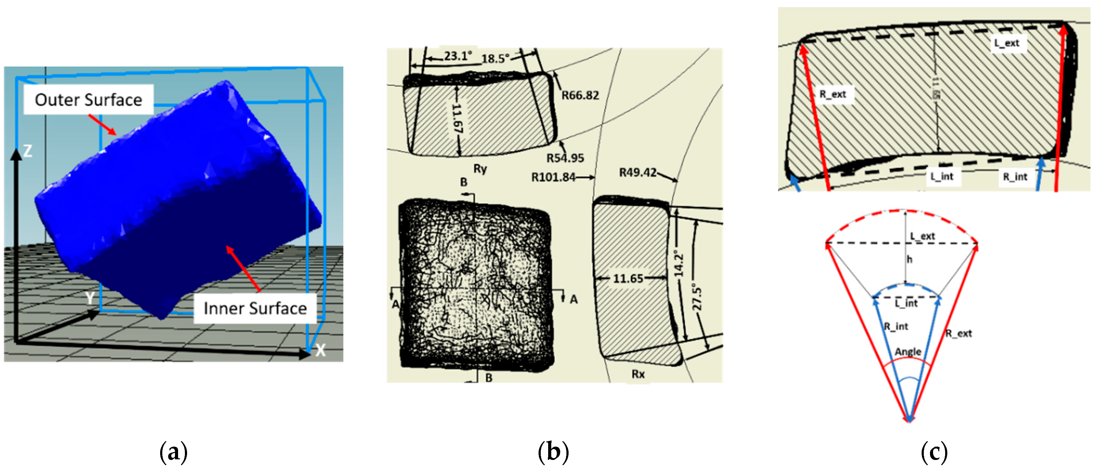
- The prosthesis 3D model, still oriented at this stage with the inclination resulting from the coordinate system of the skull scan (see Figure 1a), must be re-oriented to properly fit the workpiece raw block to be machined. The latter is automatically selected among the number of standards available in stock at the hospital, based on the dimension of the prosthesis to be realized and after an iterative procedure in which the prosthesis is reoriented to minimize the quantity of scraps.
- The path and trajectories to be followed by the tool center point (TCP) of the mill need to be computed and generated, with the constraint that inner and outer surfaces (defined by the Rint and Rext radii of Figure 1) are manufactured one side at once (see Section 4). The task of limiting robot movements inside a specific workspace might also be needed [17].
- The code instructions to command a robotic system with the designed trajectory must be generated and uploaded on a at least four DOF machine (plus one more DOF for tool rotation) (Section 5).
- Once the prosthesis has been finished, it could be removed, sterilized, and directly used by the surgeon. At most, burs should be removed with tools already available in the surgery room.
Figure 1a reports an example of the digital model of a prosthesis and Figure 1b the corresponding draft on the XY plane, also representing two sections (AA and BB) in the two main directions. The dimensions of each prosthesis are classified, as defined in Figure 1c, by considering the radii (external R_ext and internal R_int), the lengths (external L_ext and internal L_int) and thicknesses along the X and Y direction, for both the external and internal surfaces.
As an example, the geometrical results of 25 opercula (deriving from five skulls), representative of the overall population of prosthesis according to the medical experts involved in the activity, are summarized as statistical results in Table 1.
3. Automatic Selection of the Raw Material Block
The three main criteria for the selection of the starting block for the manufacturing of the workpiece are as follows:
- Processing waste shall be as minimal as possible.
- The starting block must be such as to allow the prosthesis manufacturing in a time shorter than surgery duration. In order to contain the manufacturing time, the inner and outer surface of the prosthesis (see Figure 1a for nomenclature) are machined one side at a time;
- A region for gripping must be considered in the lower-center area of the raw block, in addition to the material volume needed for the workpiece.
The digital model of the prosthesis to be manufactured shall undergo few preliminary operations before being exploited for the automatic selection of the starting raw block. After the model file is read, non-manifold tests are carried out at first (e.g., aimed at identifying self-intersecting geometries or open surfaces), followed by mesh reconstruction when needed. Since the non-manifold check is likely to be time consuming due to the size of the mesh, redefined points are removed.
The algorithm exploited for the identification of the best starting block dimensions is first in charge of defining the orientation of the prosthesis digital model within this raw block, to better fit its dimensions and to minimize the volume to be machined, thus reducing material waste. Figure 1a shows an example of the orientation the original model is likely to have at the beginning of this reorientation procedure.
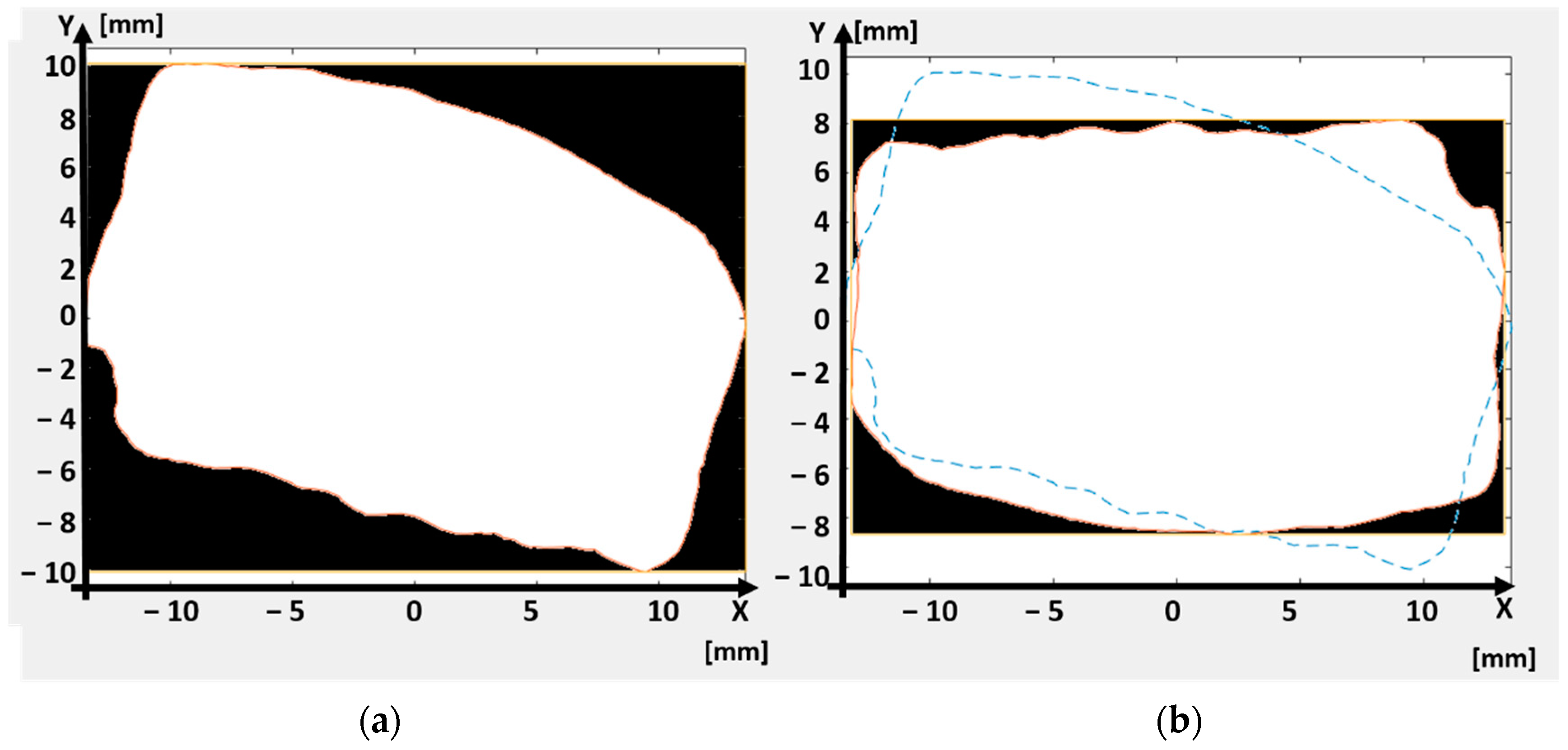
The process starts with the definition of the reference system, whose origin is placed in the center of the rectangle circumscribing the model projection in the XY plane. Figure 2 represents the way the algorithm works: The prosthesis volume is firstly projected on the XY plane (projection marked with white shape, Figure 2a), and a plane bounding box is then evaluated, defining the minimum dimensions of the block required in this XY plane (i.e., black box, Figure 2a). The difference between the area of the prosthesis projection and the area of the bounding box is then evaluated through the application of the Gauss formula [18], quantifying in such a way the amount of material to be machined in this plane and, thus, the wasted material.
An iterative cycle allows then minimizing the difference between the prosthesis projection and the bounding box area: the 2D contour is iteratively turned with predefined steps of angular increase, around one axis at once (i.e., axis Z when considering projection on XY plane). For each step, a new bounding box is evaluated, and the difference between the prosthesis projection area and the bounding box area is updated. Once the rotation range selected in the software is completely investigated (e.g., 180 degrees), the Z-axis angular position is established. During the minimization, a constraint is set to keep the longest side of the bounding box oriented along the x-axis direction and the shortest side along the y-axis direction of the reference frame, which will be exploited in the procedure for the generation of the tool center point (TCP) trajectories as described in the following Section 4.
Figure 2b shows an example of the oriented workpiece at the end of this minimization procedure. The dashed blue line represents the original orientation as in Figure 2a, whereas the white contour represents the final orientation of the workpiece. The dimensions of the bounding box in this final configuration are smaller than those of Figure 2a, meaning that a smaller raw block can be adopted. Moreover, the area included between the bounding box and the prosthesis projection (black area in the figure), representing the amount of material to be machined, is much smaller in Figure 2b than Figure 2a.
After having oriented the workpiece in the XY plane, the procedure for the minimization of the residual area is repeated first in the XZ and finally in the YZ planes. The prosthesis 3D geometry is projected into one plane at once, and the areas of the projected geometry and of the corresponding bounding box are evaluated through Gauss formula.
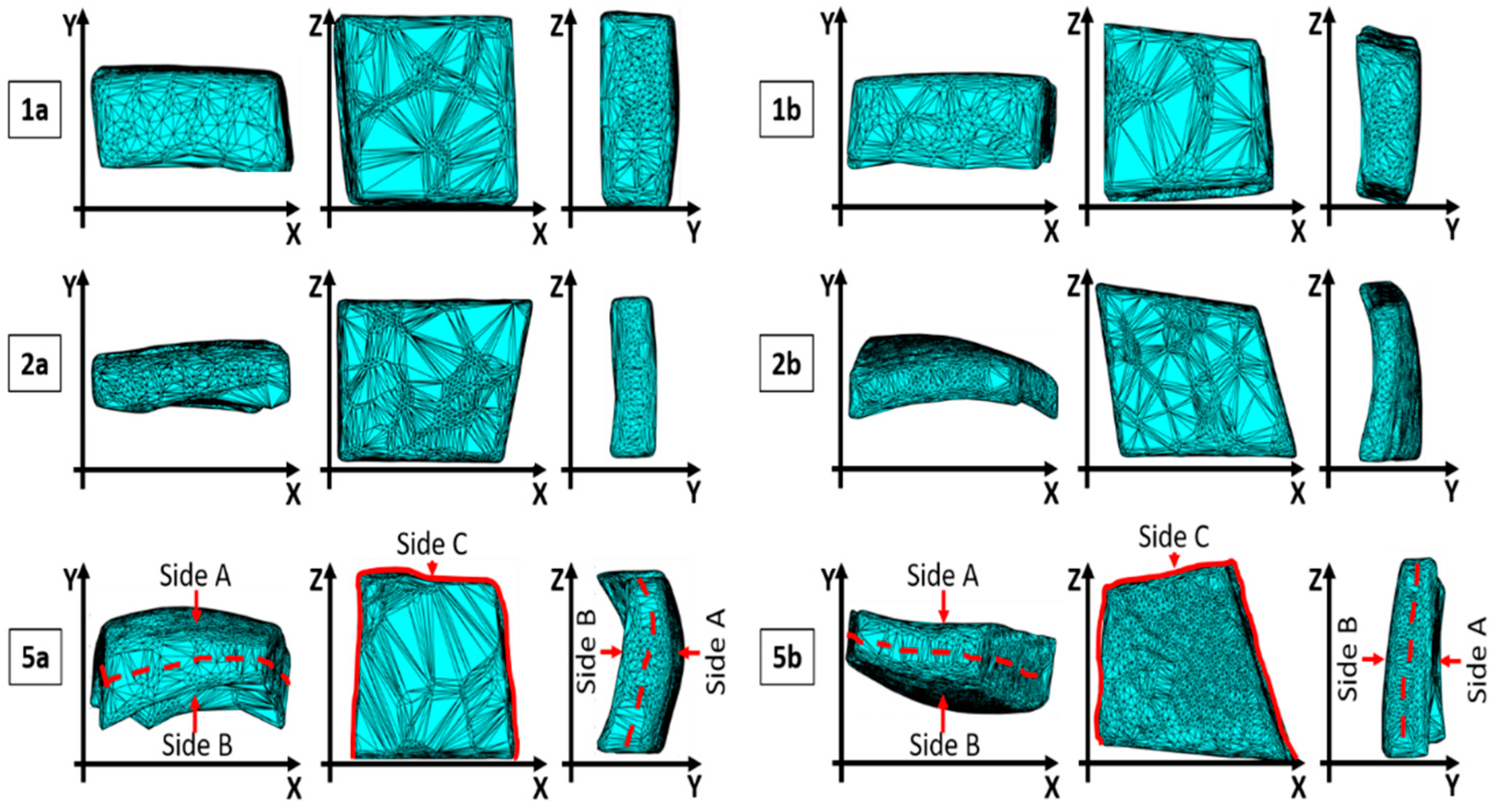
Table 2 reports, as an example, the values of residual areas obtained for 6 sample of prosthesis, out the 25 analyzed. For each of the reported samples (i.e., 1a, 1b, 2a, 2b, 5a, 5b) the algorithm execution is carried out on XY, XZ, and YZ planes in sequence. After operating on each plane, the residual area achieved in the previous planes are slightly changed, so that the overall procedure is repeated with further runs until no significant variations are encountered with respect to the previous one.
Table 3 reports, for the same cases as in Table 2, the machinery time which would be required to realize the prosthesis in the original placement of the 3D digital model (i.e., the one oriented as the skull geometry), after the first run of the algorithm for orientation, and so on. It can be observed how the orientating procedure significantly reduces the machinery time right after the first run. Non-negligible differences can also be observed between run 1 and the end of run 3.
Figure 3 represents the final orientation in the XY, XZ, and YZ plane, respectively, for the cases reported in Table 2 and Table 3.
At the end of the execution of the algorithm, the digital model of the prosthesis is suitably oriented within a rectangular parallelepiped, whose dimensions give indications for the selection of the starting block of raw material. Before giving the ultimate indication and to allow for the block selection, the dimensions of the raw material block are increased by adding a gap in the z direction, in the x direction, and for the entire thickness of the raw block along y-direction. These dimensions are configurable parameters in the procedure (e.g., z_gap_block and x_gap_block), selectable on the basis of the dimensions of the gripping device and on the cutting tool exploited in the robotic cell. This additional material is added to create a margin at the top and bottom of the workpiece during the contouring phase, needed to grip the workpiece and to prevent the milling cutter from overrunning the prosthesis surface.
After the final dimensions of the starting raw block have been identified, the developed software can output on the screen in the operating room the numeric code of the raw block to be select from the ones available in stock (selected from a database) and give indications on how to properly install it on the machine.
4. Software for Generating the Tool Centre Point (TCP) Trajectories
This section describes the way TCP trajectories and robot commands are automatically generated starting from the oriented digital model obtained through the algorithm described in the previous section. Compared to previous research works dealing with the issue of automated computer-aided process planning (ACAPP) [19], the present application does not require the automatic selection of a specific cutting tool [20], which can be preliminary identified, once and for all, during the setup phase of the cutting parameters (see Section 5) and based on the material adopted. Moreover, the absence of specific features like pockets or holes in the geometry of the prosthesis (see Figure 1a) allows the development of a trajectory planning algorithm as simple as possible, compared to other state-of-art works [21]. The algorithm shall not indeed be designed to work with general sculptured surfaces [20], but it must be a special-purpose code specifically designed to work with a dedicated geometry. This enables the possibility to obtain a very stable process, avoiding in any case any manned procedure for checks, which could not be acceptable in the considered application.
4.1. Steps of the Machinery Procedure
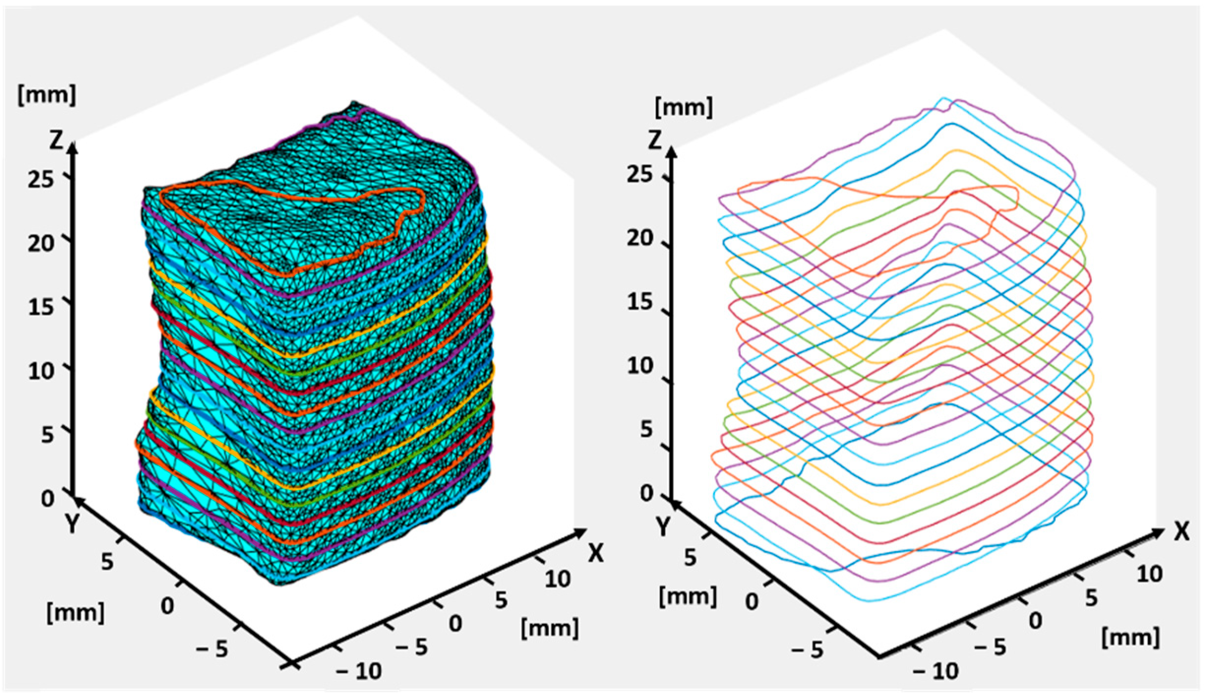
The generation of the tool path starts by cutting the oriented 3D model with planes, parallel to the XY plane (see Figure 4) and suitably spaced. The spacing of the layers can be set according to the depth of each desired tool pass (h_layer). The slicing returns a contour of the workpiece per each layer, identified by finding the intersection between the slicing layer and the prosthesis model. An example of the obtained contours is represented in Figure 4. The adopted algorithm is a self-developed algorithm for conventional slicing (i.e., plane-triangle intersection combined with loop closure), already exploited for other manufacturing applications [22].
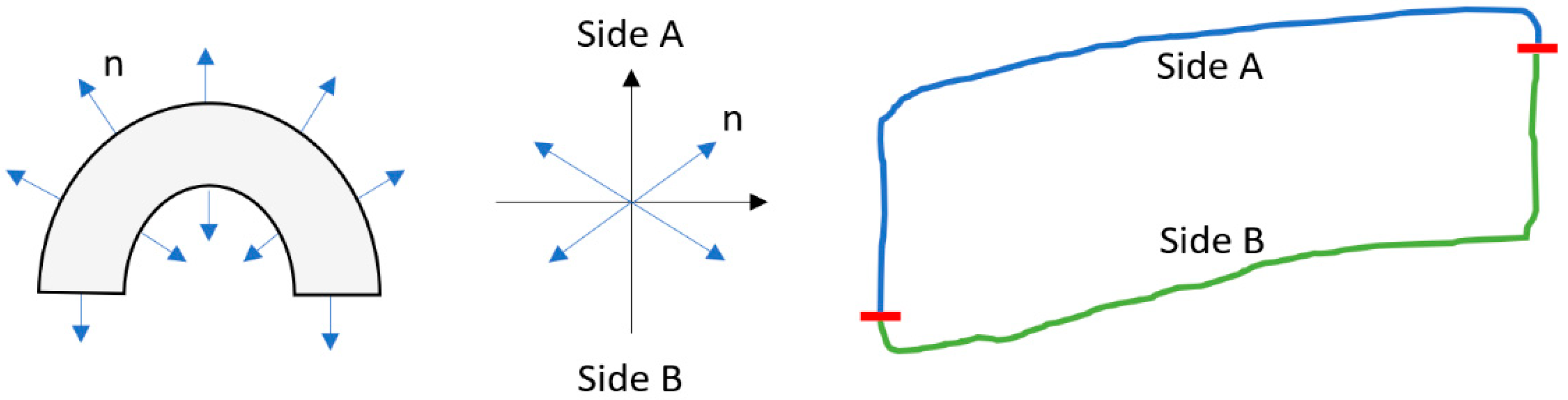
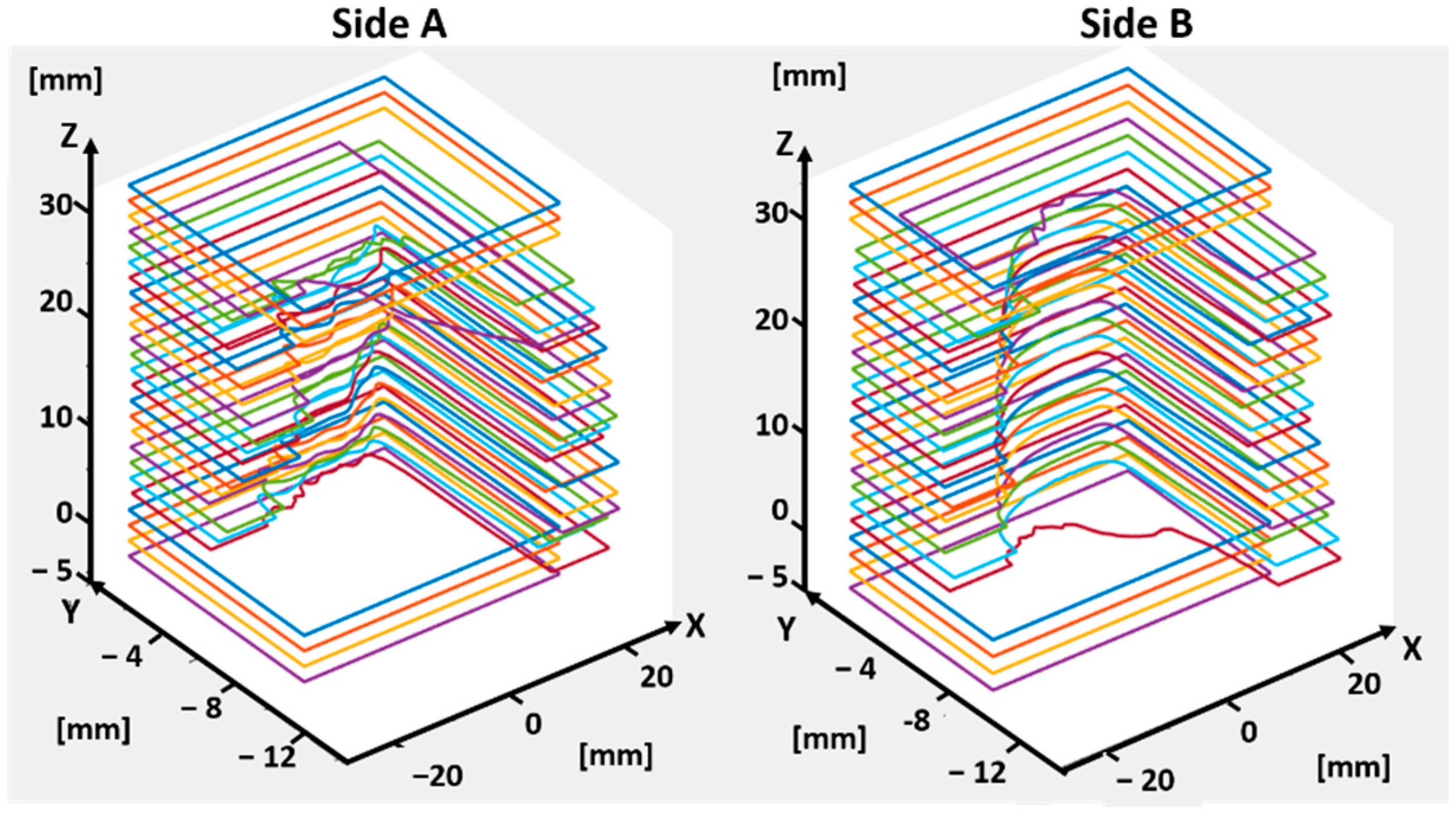
After the contours are generated, the algorithm identifies three separate portions of the prosthesis, so that the process of material removal can be divided in three phases: the first one is related to the machining of the prosthesis outer side (referenced as side A, see Figure 3); the second one is related to the machining of the inner side (referenced as side B, see Figure 3); the third one, referenced as side C (see Figure 3), is related to the remaining contour, as described in the following. The procedure for the identification of these three parts is based on the vectors normal to each segment constituting the contours of Figure 4, evaluated through the cross product between the unitary vector defining the orientation of each segment (following the contour in a clockwise manner) and the unit vector normal to each slicing plane. The angular position associated to each normal vector can then be exploited to identify the quadrant in which each vector lays. The procedure is described in Figure 5: if the angle defining the normal orientation is included in the first or second quadrants, the corresponding segment is associated to side A. If the angle is included in the third or fourth quadrants, the corresponding segment is associated to side B.
After identifying sides A and B, the volume of material to be removed can be recognized for each of the two sides, as reported in Figure 6.
The process for material removal is conceived to be carried out with the processing of side A first, and of side B afterwards. When starting the machining, the tool is in the home position, with the workpiece platform oriented to show the side A to the milling cutter. The TCP is positioned in the center of the region where the block will be chiseled, coincident with the origin of the local reference frame. After finishing side A, the tool exits the stock, allowing the platform to be rotated and side B to be machined.
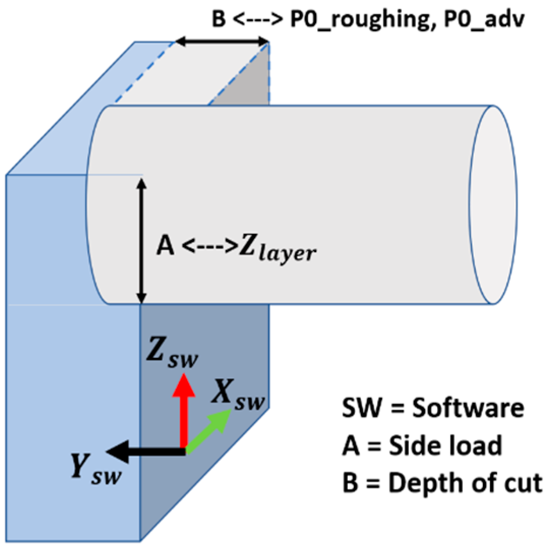
Figure 7 reports the orientation of the tool with respect to the workpiece reference frame (XSW, YSW, ZSW).
To guarantee that the workpiece is kept steady during the entire machinery, a narrow strip of material is maintained around the entire prosthesis during the machinery of sides A and B, so that it remains connected to the stock. To obtain this strip, the milling tool has to remove the material along the y-axis up until a certain depth (see Figure 8A,B). A representation of the “holding strip” is reported in the scheme of Figure 8C. It is referred to as side C. Its geometry is computed automatically in accordance with the geometry of the prosthesis, to make sure that there will be no chance of an unsteady placement of the part or even premature separation of the workpiece from the raw block, which would corrupt the quality of the final part. This machining approach increases the reliability of the overall process.
The third and last phase of the machinery procedure then consists in the removal of this anchoring strip (Figure 8D), to completely separate the prosthesis from the stock. The width of the holding strip is set automatically by the software so that it can be machined in one single pass, following the tool path obtained by projecting the prosthesis geometry in the XZ plane, as described in the Section 4.2. In order to guarantee the highest possible rigidity of the to-be-machined part along the toolpath, a residual strip of material is left at its bottom at the end of this job, so that the prosthesis is not completely detached from the block through the robotic milling procedure. A subsequent job will be in charge of separating the prosthesis and bring it to the sterilization chamber.
4.2. Generation of Toolpath Trajectories
The generation of the toolpath trajectories [23] for sides A and B is carried out by intersecting the volume of material to be removed, identified in Figure 6, with planes parallel to the XZ reference plane. The distance between subsequent planes depends on the type of pass to be generated, which can either be a roughing or smoother pass. In all the zones where the cutting plane parallel to XZ does not intersect the operculum, a roughing pass can be performed, allowing a great time reduction. On the contrary, when the plane intersects the geometry of the prosthesis, smoother passes are implemented.
The intersection of the mentioned planes with the prosthesis geometry is detected by evaluating the distances between each plane and the points belonging to the prosthesis contours, previously identified and reported in Figure 4: if the oriented distances between the plane under analysis and two subsequent points show the same sign, both the points lay on the same side with respect to the plane. On the other hand, if the distances show opposite sign, an intersection between the segment and the plane is identified.
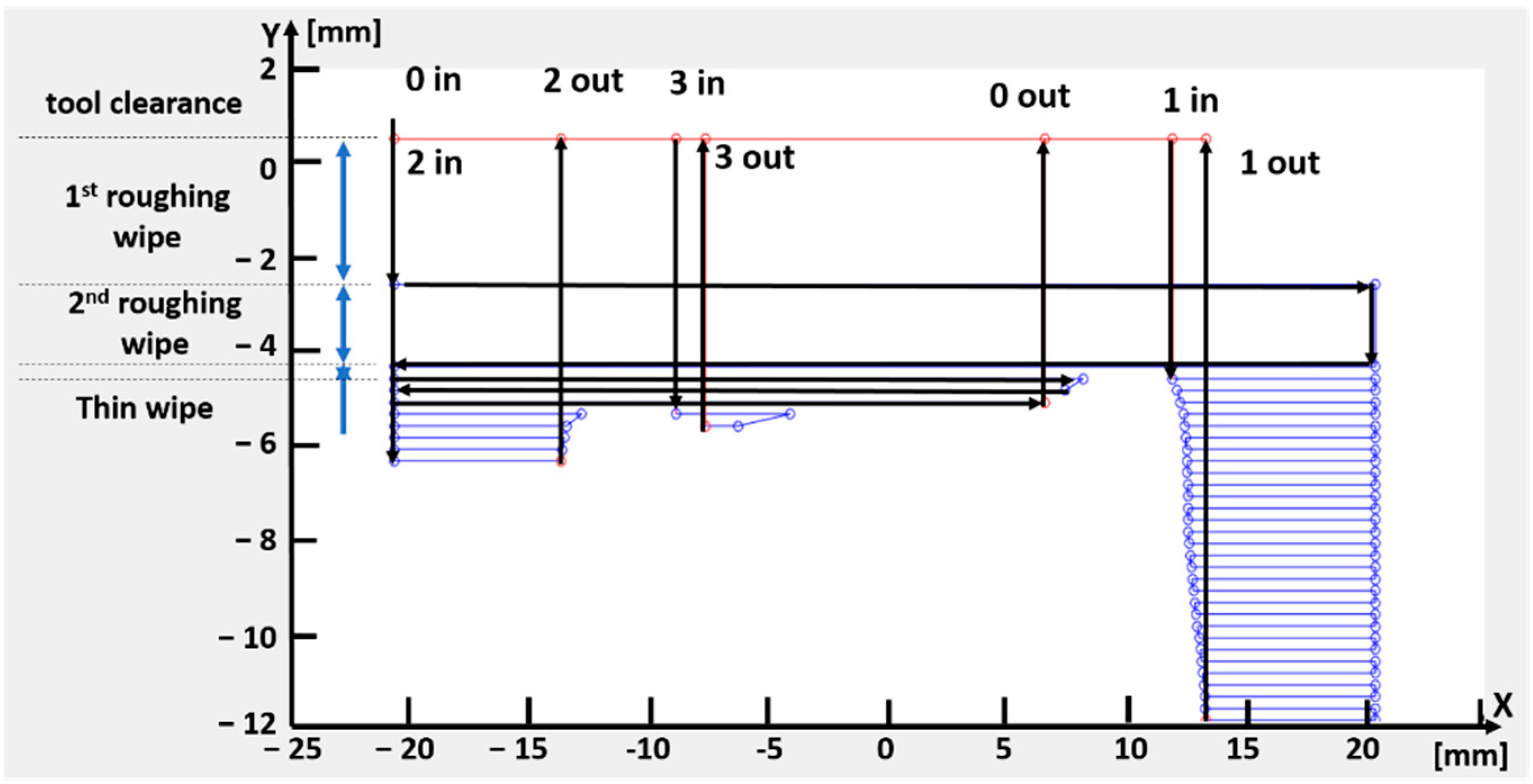
The designed toolpath starts from a point generated at a certain distance (tool clearence) in the mill direction of advancement (i.e., –Ysw direction in Figure 7) from the first plane cutting the workpiece. The algorithm function then looks for the closest point, which can either lay on the same plane (i.e., same pass) or on the following plane along the axial direction (i.e., next pass), generating in such a way the entire tool path. Figure 9 reports an example of the final trajectories. When dealing with the points belonging to the prosthesis contour, the algorithm shall avoid milling part of the operculum [24]: it is able to discern the sequence of points found on the same plane, automatically retracting the cutter and jumping the prosthesis zone, to re-enter the workpiece where needed. The exemplary toolpath trajectories highlight the first and second roughing wipe, and the thin wipes adopted when the cutting planes intersect the prosthesis geometry.
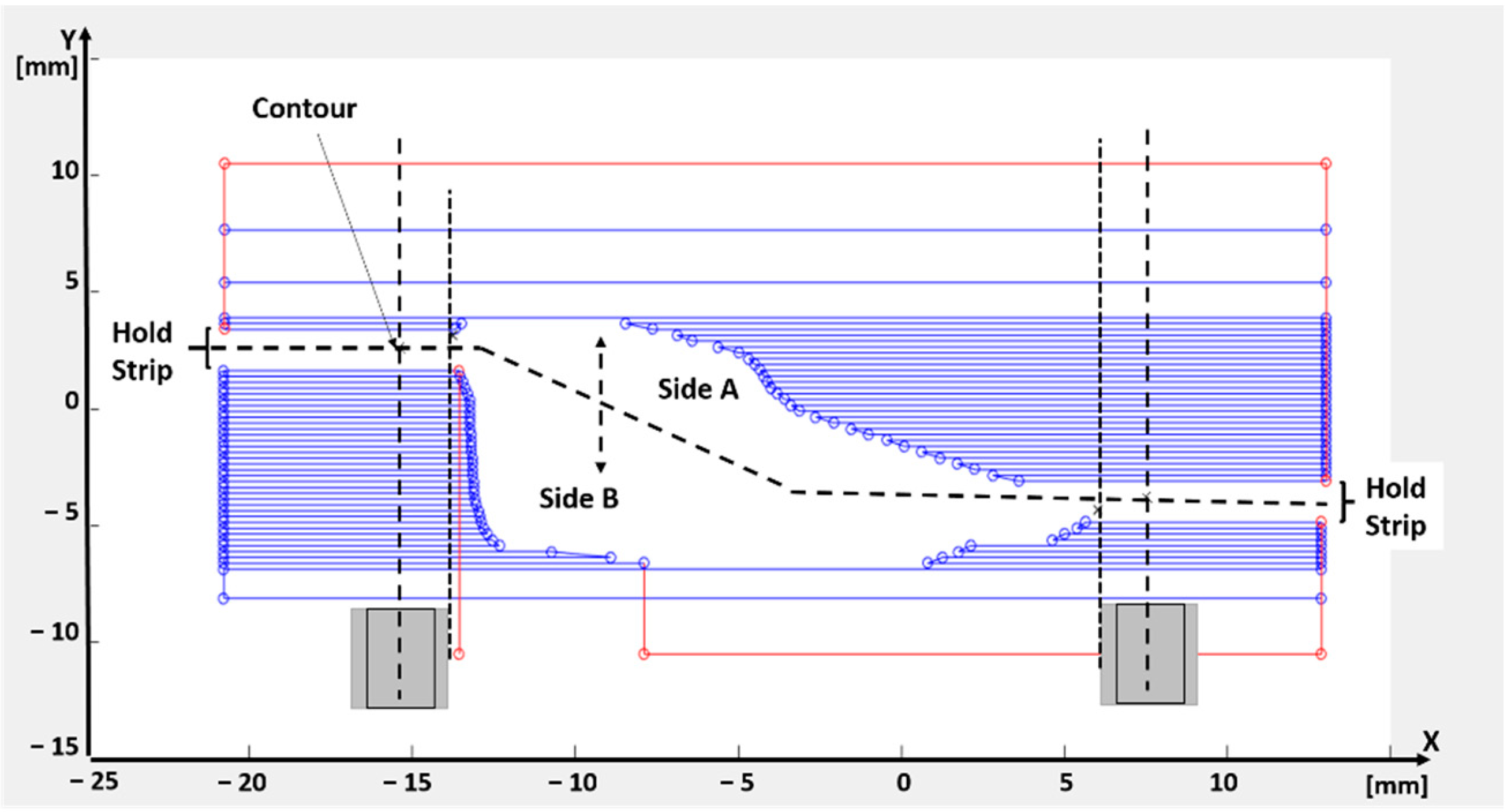
Figure 10 shows the trajectory result for a section parallel to XY plane, highlighting the machining of sides A and B. At the end of machining of sides A and B a last trajectory is defined by linking all the points of the prosthesis contour, to define a last finishing pass to reduce the quantity of residual burr on the prosthesis surface.
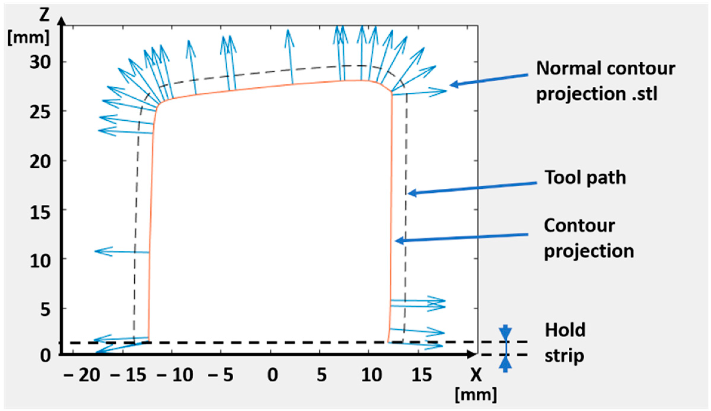
The tool trajectories for the machining of side C are finally identified by projecting the 3D model of the holding strip onto the XZ plane and reconstructing the profile of the contour by using alpha shape boundary detection. An example of this projection is reported in Figure 11: the path to be followed by the TCP is constructed using the projected contour (i.e., the orange continuous line in Figure 11), its normal unitary vectors and the bit radius. The final toolpath is represented with a dashed line in the figure (labelled as tool path).
4.3. Generation of the Machine Code
A further section of the developed code automatically generates the code instruction needed to command a robotic system with the designed TCP trajectory (e.g., a G-code when the robotic system adopted is able to read it). It is composed of three phases, listed as follows:
- Referring the trajectories to the machine reference system.
- Check for required corrections, to make sure the points are still compliant with the machine limits and check for machining time. As for the latter, the software checks the expected machining time and compare it the maximum allowed, depending on the surgery time. The estimation of the machining time is done by summing the duration of each linear interpolation obtained by connecting two consecutive points of the final toolpath, assuming a constant velocity. This approach is chosen for its computational simplicity: the contribution of the acceleration times has been discarded under the assumption that the motion planner is governed by a look ahead algorithm that tends to guarantee the commanded speed throughout the toolpath (hence improving the quality of the subtractive process), making the time contribution related to acceleration phases marginal.
- Writing the robot code: A code function autonomously translates the arrays of points defining the computed toolpath into machine instructions. This routine takes as input the points of side A, side B and side C obtained from the above described procedure and returns the machine code file. As for example, in the case of G-code, this file starts with information related to the setup of the machine and to the local reference frames that the machine will have to use for side A. The trajectories are then automatically printed in the text as G-code functional blocks: for instance, movements that engage the mill with the stock are defined as “G1 X<Px> Y<Py> Z<Pz> F<Feed1>” (where Px, Py and Pz are the coordinates to be reached with a linear interpolation, and Feed1 is the target TCP velocity defined in the next section). The repositioning movements of the mill use G0 instead of G1. This operation is executed also for the side B, after having run a rotation of 180° of platform holding the workpiece. Lastly, the contour is appended to the file. It then ends with go-to-home position and with turn-the machine off.
5. Experimental Tests
In order to validate the trajectory planning software, an available CNC machine has been used as if it were a robot, feeding the controller with a G-code automatically output by the developed algorithm, starting from the digital model of a reference prosthesis having dimensions Rx_ext = 252 mm, Rx_int = 238 mm, Ry_ext = 255 mm, Ry_int = 244 mm. For the tests described in this section, a five-axis CNC milling machine was available (Pocket NC V2, Belgrade, MT, USA, Resolution: 6.10 microns (XYZ), 0.01° (A and B); Speed: 1524 m/min (XYZ), 40°/s; Spindle speed: 2–10 kRPM). Experimental tests have been carried out to check the software behavior and to set the most suitable parameters and hardware for the machining the selected material (the latter is not mentioned here, since the entire process is under the patenting process by an industrial company partner of this work).
5.1. Setting of Working Parameters
The process parameters are listed in Figure 12. The top of Figure 12a represents a side view of the block under machinery, whereas the bottom of Figure 12b the top view. None of the parameters indicated in the figure, exploited by the software to generate the toolpath, must be initialized by the operator (i.e., the surgeon), who should be exempted as much as possible from technical evaluations about the machinery process. For this reason, the experimental tests described in this paragraph are aimed at identifying the best parameters for the selected material, to be pre-set in the final software actually used in the hospital to operate the machinery.
In the experimental campaign carried out, the process parameters are grouped into two categories, the first one enclosing those that are kept constant during the tests, the second one including parameters that can be tuned to improve the machining operation.
The parameters kept constant during the experiments are the mill diameter (d_m, see Figure 12a), the first side load (h_layer0) always equal to half of the mill diameter, the gap left between the mill and the raw block to assure a safe and fast repositioning of the TCP with respect to the workpiece surface (Tool_clearance), and the speed related to this movement (named Feed0, since it is related to G0 blocks in the G-code). Additionally, the width of holding strip that constrains the part to the stock until the final contouring is carried out (p0_adv) and the depth of roughing passes (p_roughing), also related to the mill diameter. Furthermore, the parameters (X_gap_block and Z_gap_block) mentioned in Section 3, used to define of the overall dimensions of the raw block, are not changed during the experiments.
On the other hand, the parameters directly related to the chip removal have been varied during the testing phase, having a direct influence on the quality of the final implant. They are the spindle speed (S), the side load (h_layer, see Figure 12a), the depth of cut (p_adv, see Figure 12b) and the speed of the TCP (named Feed1, since it is related to G1 blocks). The optimal set for these parameters depends on the material to be machined and on the characteristics of tool used.
The prosthetic plates are machined from a polymeric material (not mentioned here in detail, since the entire process is under patenting process by an industrial company partner of this work). As indicated by the mill producer, two types of setting can be used as a starting point in the fine-tuning process based on the plastic hardness, indicated as hard and soft plastic. They are indicated in Table 4.
The side load and the depth of cut in Table 4 are indicated as a percentage of the mill diameter. The diameter of the selected mill cutter being 3.175 [mm] (1/8 inch), the axial and radial depths of the cut can be computed based on the depth of cut and side load parameters, respectively. For example, in the case of “hard plastic”, the axial depth of cut (i.e., p_adv in Figure 12) is 2.54 mm, whereas the radial depth of cut (i.e., h layer in Figure 12) is 1.5875 mm.
The feed per tooth parameter allows evaluating the TCP speed (i.e., Feed1 in Figure 12), computed as:
Feed1 [mm/min] = feed per tooth [mm] ∗ teeth number ∗ Speed (RPM)
In order to contain the temperature during cutting [25] and, therefore, to obtain optimal performance and surface results, a single cutter tool is exploited (i.e., teeth number equal to 1). Hence, in the case of “soft plastic”, for instance, the feed1 value is equal to 323.85 mm/min.
5.2. Results
Tests have been conducted using both the specifics for “hard” and “soft” plastic. Better results have been achieved for the “soft plastic” parameters: in this case the residual material remained at the end of working was almost null and the burrs have been easily removed using rotary tools for deburring, leaving the operculum clean.
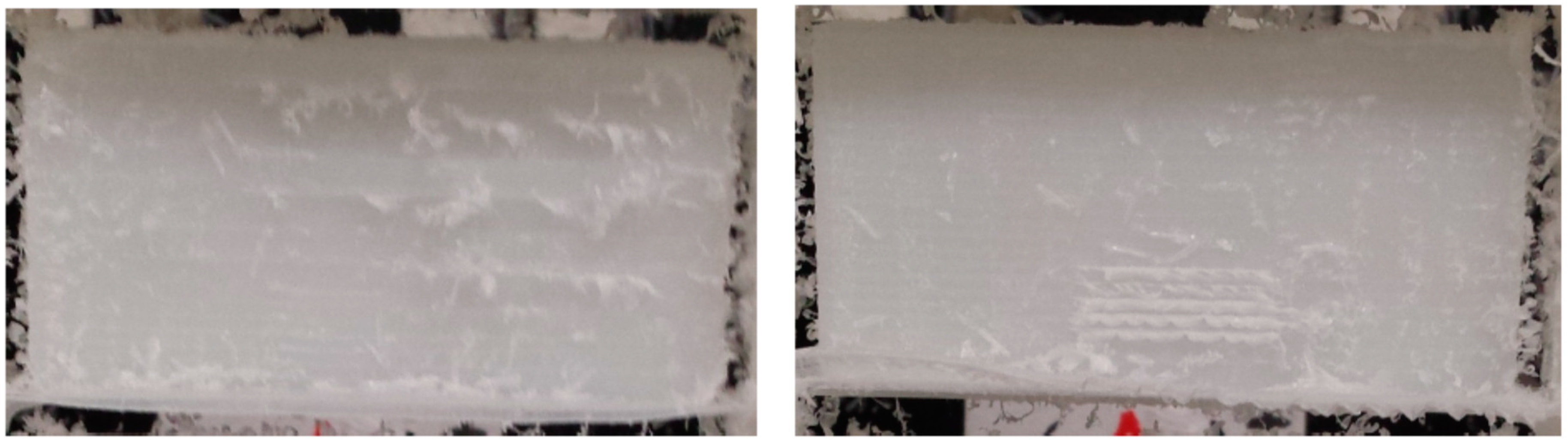
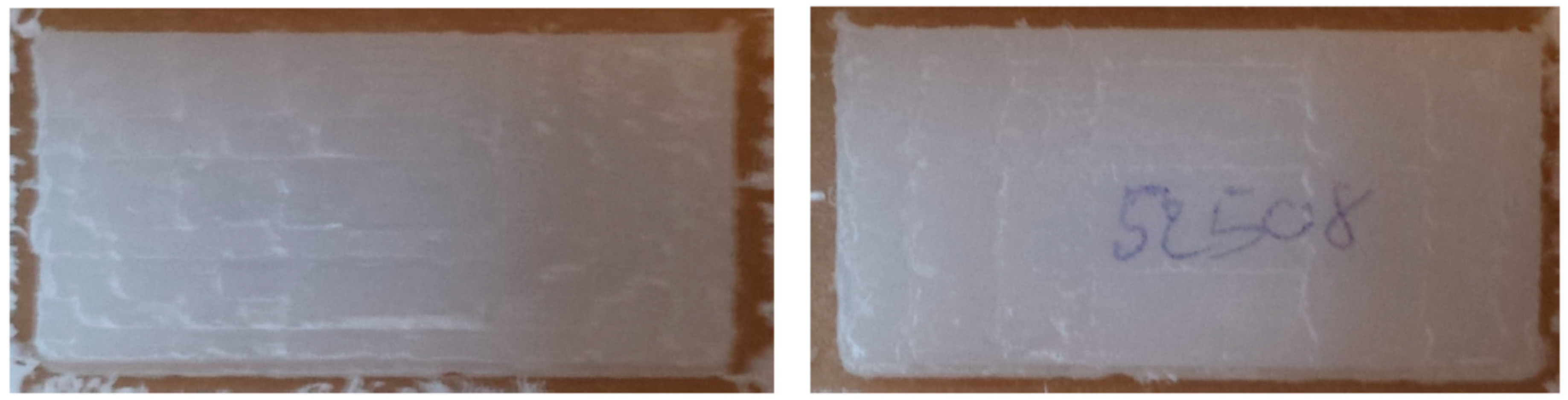
The final prosthetic device can be found in Figure 13 right after the milling operation, and in Figure 14, after cleaning through a rotary tool (brush with 80 grit size at 50% of the maximum speed of the device, max speed 35 kRPM).
It can be observed as the final surfaces in Figure 14, after deburring, are rather regular and well-finished.
The experimental tests demonstrated the possibility to automatically produce the prosthetic device within the time required by the surgery, and with good finishing of the workpiece.
Moreover, the results achieved through a prototype demo demonstrated the feasibility of having the prosthesis manufactured on-site. The entire process could be automatized by means of an automatic robotic cell, starting from the raw material block and getting to the final sterilized prosthesis. The same robotic system would indeed place the raw workpiece, machining it with the proper tool and, once the machinery is over, grip the workpiece and place it into a sterilizing machine. At the end of the process, the prosthesis could then be directly used by the surgeon.
The installation process in an actual hospital would entail the adoption of the robotic cell in a dedicated sterile environment. To this aim, the final design should make use of robots suitably designed for sterile applications, which are already available on the market. They are able to handle decontamination processes through vapor or fluid, and they are designed with special joints and a structure featuring an IP65 degree of protection.
6. Conclusions
The paper presented an algorithm for the generation of an automatic robotic procedure for machining of skull prosthesis. The setup procedure allows to manufacture the prosthesis in real-time during the surgery, based on the actual cut carried out by the surgeon and within the time required to complete the operation.
The input for the algorithm is a digital model of the prosthesis to be realized, which is processed to generate the trajectories to be followed by a robotic system for the manufacturing of the workpiece. A first step of the procedure allows to identify the best placement of the workpiece into the raw material block, to reduce material waste and to identify, at the same time, the dimension of the raw material block needed for machining. This would allow the automatic selection of the raw block between those available, registered in a database, thus reducing the activities to be carried out by medical personnel. The latter should only follow instructions on a monitor to place the proper working piece into the machine.
As a second step, the algorithm automatically generates the toolpath trajectories to be executed on the machine, through an automatic process derived from a slicing procedure. The latter allows to generate zig-zag trajectories to be followed by the milling tool, which is a simple but stable trajectory planning method allowing a straightforward and automatic coding of the toolpath into the program for robot movements. A four d.o.f. at least machine is required, plus one more d.o.f. for tool rotation. To this regards, either six d.o.f manipulators or five-axis Cartesian robot may be exploited for the application.
The results of the prosthesis realized show the good behavior of the automatic procedure, demonstrating the possibility to produce the operculum within the duration of the operation, thus increasing the accuracy of the produced prosthesis and consequently reducing the surgery time. The possibility to realize the prosthesis through a milling machine enables the adoption of plastic material which can undergo radiotherapy without the need to remove the prosthesis from the cranium.
The approach proposed allowed to demonstrate the possibility to automatize the entire production process, thus introducing a fully automated process in a hospital environment. Starting from the digital model of the prosthetic device to be realized, the automation of the orientation of the workpiece within the raw block, the generation of end effector trajectories through an unmanned stable procedure, and finally the automatic programming of the robotic machine, constitute a preparatory work to introduce the automation process in a surgery room. The medical personnel are not expected to operate the machine, except for simple operations like placing the raw block into the machine, authorize the start of the entire procedure, and possibly remove burs using rotary tools for deburring.
Future research should consist in the design of a complete robotic cell, in which the raw block is automatically placed for machining and, once the machinery is over, the prosthesis is gripped and automatically placed into a sterilizing machine. From a procedural point of view, a further future work is related to the development of a specific procedure for the accreditation of the sterile process.
Author Contributions
Conceptualization: H.G., M.C., K.C.; methodology: H.G., K.C.; software: K.C.; validation: K.C.; formal analysis: M.C.; investigation: H.G., K.C.; data curation: K.C.; writing—original draft preparation: M.C.; writing—review and editing: M.C.; visualization: K.C., M.C.; supervision: H.G.; project administration: H.G.; funding acquisition: H.G. All authors have read and agreed to the published version of the manuscript.
Funding
This research received no external funding.
Conflicts of Interest
The authors declare no conflict of interest.
References
- Peruzzini, M.; Wognum, N.; Bil, C.; Stjepandic, J. Special issue on ‘transdisciplinary approaches to digital manufacturing for industry 4.0’. Int. J. Comput. Integr. Manuf. 2020, 33, 321–324. [Google Scholar] [CrossRef]
- Ghosh, U.; Ning, S.; Wang, Y.; Kong, Y.L. Addressing Unmet Clinical Needs with 3D Printing Technologies. Adv. Healthc. Mater. 2018, 7, e1800417. [Google Scholar] [CrossRef]
- Radenkovic, D.; Solouk, A.; Seifalian, A. Personalized development of human organs using 3D printing technology. Med. Hypotheses 2016, 87, 30–33. [Google Scholar] [CrossRef] [Green Version]
- Dobrzański, L.A. Overview and general ideas of the development of constructions, materials, technologies and clinical applications of scaffolds engineering for regenerative medicine. Arch. Mater. Sci. Eng. 2014, 69, 53–80. [Google Scholar]
- Dean, D.; Min, K.-J.; Bond, A. Computer Aided Design of Large-Format Prefabricated Cranial Plates. J. Craniofacial Surg. 2003, 14, 819–832. [Google Scholar] [CrossRef]
- Chrzan, R.; Urbanik, A.; Karbowski, K.; Moskała, M.; Polak, J.; Pyrich, M. Cranioplasty prosthesis manufacturing based on reverse engineering technology. Med. Sci. Monit. 2012, 18, MT1–MT6. [Google Scholar] [CrossRef] [Green Version]
- Guillaume, O.; Geven, M.A.; Varjas, V.; Varga, P.; Gehweiler, D.; Stadelmann, V.A.; Smidt, T.; Zeiter, S.; Sprecher, C.; Bos, R.R.; et al. Orbital floor repair using patient specific osteoinductive implant made by stereolithography. Biomaterials 2020, 233, 119721. [Google Scholar] [CrossRef]
- Gander, T.; Essig, H.; Metzler, P.; Lindhorst, D.; Dubois, L.; Rücker, M.; Schumann, P. Patient specific implants (PSI) in reconstruction of orbital floor and wall fractures. J. Cranio Maxillofac. Surg. 2015, 43, 126–130. [Google Scholar] [CrossRef] [Green Version]
- Stoor, P.; Suomalainen, A.; Lindqvist, C.; Mesimäki, K.; Danielsson, D.; Westermark, A.; Kontio, R.K. Rapid prototyped patient specific implants for reconstruction of orbital wall defects. J. Cranio Maxillofac. Surg. 2014, 42, 1644–1649. [Google Scholar] [CrossRef]
- Schlittler, F.; Vig, N.; Burkhard, J.P.M.; Lieger, O.; Michel, C.; Holmes, S. What are the limitations of the non-patient-specific implant in titanium reconstruction of the orbit? Br. J. Oral Maxillofac. Surg. 2020. [Google Scholar] [CrossRef]
- Tarsitano, A.; Battaglia, S.; Crimi, S.; Ciocca, L.; Scotti, R.; Marchetti, C. Is a computer-assisted design and computer-assisted manufacturing method for mandibular reconstruction economically viable? J. Cranio Maxillofac. Surg. 2016, 44, 795–799. [Google Scholar] [CrossRef] [PubMed]
- Kozakiewicz, M.; Wach, T.; Szymor, P.; Zieliński, R. Two different techniques of manufacturing TMJ replacements—A technical report. J. Cranio Maxillofac. Surg. 2017, 45, 1432–1437. [Google Scholar] [CrossRef] [PubMed]
- Huang, G.-Y.; Shan, L.-J. Research on the Digital Design and Manufacture of Titanium Alloy Skull Repair Prosthesis. In Proceedings of the 2011 5th International Conference Bioinformatics Biomedical Engineering, Wuhan, China, 10–12 May 2011. [Google Scholar] [CrossRef]
- Keeratihattayakorn, S.; Tangpornprasert, P.; Prasongcharoen, W.; Virulsri, C. Out-of-roundness compensation technique in machining of femoral head prosthesis using conventional CNC machine. Int. J. Adv. Manuf. Technol. 2020, 107, 2537–2545. [Google Scholar] [CrossRef]
- D’Urso, P.S.; Effeney, D.J.; Earwaker, W.J.; Barker, T.M.; Redmond, M.J.; Thompson, R.G.; Tomlinson, F.H. Custom cranioplasty using stereolithography and acrylic. Br. J. Plast. Surg. 2000, 53, 200–204. [Google Scholar] [CrossRef] [PubMed]
- Lee, S.-C.; Wu, C.-T.; Lee, S.-T.; Chen, P.-J. Cranioplasty using polymethyl methacrylate prostheses. J. Clin. Neurosci. 2009, 16, 56–63. [Google Scholar] [CrossRef]
- La Mura, F.; Romanó, P.; Fiore, E.; Giberti, H. Workspace Limiting Strategy for 6 DOF Force Controlled PKMs Manipulating High Inertia Objects. Robotics 2018, 7, 10. [Google Scholar] [CrossRef] [Green Version]
- Beyer, W. CRC Standard Mathematical Tables and Formulae; CRC Press: Boca Raton, FL, USA, 1996. [Google Scholar]
- Al-Wswasi, M.; Ivanov, A.; Makatsoris, H. A survey on smart automated computer-aided process planning (ACAPP) techniques. Int. J. Adv. Manuf. Technol. 2018, 97, 809–832. [Google Scholar] [CrossRef] [Green Version]
- Lin, A.C.; Gian, R. A Multiple-Tool Approach to Rough Machining of Sculptured Surfaces. Int. J. Adv. Manuf. Technol. 1999, 15, 387–398. [Google Scholar] [CrossRef]
- Bieterman, M.B.; Sandstrom, D.R. A Curvilinear Tool-Path Method for Pocket Machining. J. Manuf. Sci. Eng. 2003, 125, 709–715. [Google Scholar] [CrossRef]
- Carnevale, M.; Castelli, K.; Zaki, A.M.A.; Giberti, H.; Reina, C. Automation of Glue Deposition on Shoe Uppers by Means of Industrial Robots and Force Control. Mech. Mach. Sci. 2020, 91, 344–352. [Google Scholar] [CrossRef]
- Giberti, H.; Sbaglia, L.; Urgo, M. A path planning algorithm for industrial processes under velocity constraints with an application to additive manufacturing. J. Manuf. Syst. 2017, 43, 160–167. [Google Scholar] [CrossRef]
- D’Antona, G.; Davoudi, M.; Ferrero, R.; Giberti, H. A model predictive protection system for actuators placed in hostile environments. In Proceedings of the 2010 IEEE Instrumentation & Measurement Technology Conference, Austin, TX, USA, 3–6 May 2010; pp. 1602–1606. [Google Scholar] [CrossRef]
- Alauddin, M.; Choudhury, I.; El Baradie, M.; Hashmi, M. Plastics and their machining: A review. J. Mater. Process. Technol. 1995, 54, 40–46. [Google Scholar] [CrossRef]
Figure 1.
Geometrical parameters for the description of the operculum geometry. (a) Digital model (b) Main sections. (c) Considered dimensions.
Figure 1.
Geometrical parameters for the description of the operculum geometry. (a) Digital model (b) Main sections. (c) Considered dimensions.

Figure 2.
Orientation of the workpiece on a single plane through minimization of residual area between the workpiece projection and the bounding box. (a) Initial orientation. (b) Final orientation.
Figure 2.
Orientation of the workpiece on a single plane through minimization of residual area between the workpiece projection and the bounding box. (a) Initial orientation. (b) Final orientation.

Figure 3.
Examples of final orientation of the prosthetic opercula.

Figure 4.
Closed profiles obtained through the slicing procedure of the oriented prosthesis.

Figure 5.
Identification of side A and side B of the workpiece through normal vectors analysis.

Figure 6.
Volume of material to be removed corresponding to sides A and B.

Figure 7.
Orientation of the tool with respect to the workpiece reference frame (i.e., XSW, YSW, ZSW).
Figure 7.
Orientation of the tool with respect to the workpiece reference frame (i.e., XSW, YSW, ZSW).

Figure 8.
Schematic view of the machining steps. (A) Machinery of Side A. (B) Machinery of Side B. (C) Holding strips left after the machinery of sides A and B (i.e., Side C). (D) Separation of the prosthesis from the stock.
Figure 8.
Schematic view of the machining steps. (A) Machinery of Side A. (B) Machinery of Side B. (C) Holding strips left after the machinery of sides A and B (i.e., Side C). (D) Separation of the prosthesis from the stock.

Figure 9.
Example of toolpath trajectories generated.

Figure 10.
Example of tool path trajectories for machining side A and B.

Figure 11.
Projection on the XZ plane for the definition of the side C tool path.

Figure 12.
Process parameters. (a) Side view. (b) Top view.

Figure 13.
Mono-cutting bid and “soft plastic”: prosthesis removed from the CNC.

Figure 14.
Mono-cutting bid and “soft plastic”: prosthesis after deburring.


Table 1.
Dimensional analysis of a set of 25 prostheses.
| Mean | Max | Mode | std | |
| Rx_ext | 82.4 | 196 | 50 | 38.78 |
| Rx_int | 85.08 | 500 | 47 | 93.532 |
| Ry_ext | 78.8 | 214 | 50 | 45.038 |
| Ry_int | 100 | 2848 | 43 | 554.9 |
| hx | 9.8 | 12 | 9 | 1.5 |
| hy | 10 | 12 | 12 | 1.5 |
| mean | max | mode | min | |
| Lx_ext | 29.68 | 45 | 30 | 19 |
| Lx_int | 30.76 | 47 | 31 | 20 |
| Ly_ext | 27.6 | 38 | 25 | 19 |
| Ly_int | 28.12 | 50 | 32 | 17 |
Table 2.
Example of residual areas at the end of the orientation procedure.
| Sample | Projection on Plane | Area after 1st Run (mm2) | Area after 2nd Run (mm2) | Area after 3rd Run (mm2) |
|---|---|---|---|---|
| 1a | XY | 49.4843 | 40.4213 | 40.4213 |
| XZ | 49.4086 | 49.2327 | 49.2327 | |
| YZ | 29.5412 | 26.1143 | 26.1143 | |
| 1b | XY | 30.2398 | 30.2398 | 30.2398 |
| XZ | 64.6581 | 64.6581 | 64.6581 | |
| YZ | 41.8535 | 41.8535 | 41.8535 | |
| 2a | XY | 74.3664 | 69.4032 | 62.4382 |
| XZ | 118.9427 | 81.0414 | 81.0965 | |
| YZ | 30.1888 | 26.9894 | 27.1190 | |
| 2b | XY | 392.1400 | 255.4181 | 252.2044 |
| XZ | 487.2517 | 365.7807 | 365.2796 | |
| YZ | 171.7894 | 131.7848 | 133.7236 | |
| 5a | XY | 164.1555 | 164.1555 | 164.1555 |
| XZ | 160.6684 | 160.6684 | 160.6684 | |
| YZ | 198.8549 | 198.8549 | 198.8549 | |
| 5b | XY | 204.3723 | 121.0910 | 111.9669 |
| XZ | 397.2964 | 385.9294 | 385.6223 | |
| YZ | 114.1317 | 89.7570 | 79.7622 |
Table 3.
Machinery time (MT) required to produce the prosthesis in the original orientation and after the orientating procedure.
Table 3.
Machinery time (MT) required to produce the prosthesis in the original orientation and after the orientating procedure.
| Sample | MT Original Orientation (min) | MT after 1st Run (min) | MT after 2nd Run (min) | MT after 3rd Run (min) |
|---|---|---|---|---|
| 1a | 78 | 44 | 41 | 41 |
| 1b | 72 | 37 | 37 | 37 |
| 2a | 94 | 53 | 50 | 48 |
| 2b | 149 | 108 | 100 | 99 |
| 5a | 189 | 90 | 90 | 90 |
| 5b | 171 | 98 | 80 | 79 |
Table 4.
Parameters recommended by the milling producer for two type for soft and hard plastic.
| Speed (RPM) | Feed per Tooth [mm] | Side Load (h_layer) | Depth of Cut (p_adv) | |
|---|---|---|---|---|
| Hard Plastic | 8500 | 0.0254 | 50% | 80% |
| Soft Plastic | 8500 | 0.0381 | 60% | 70% |
Publisher’s Note: MDPI stays neutral with regard to jurisdictional claims in published maps and institutional affiliations. |
© 2020 by the authors. Licensee MDPI, Basel, Switzerland. This article is an open access article distributed under the terms and conditions of the Creative Commons Attribution (CC BY) license (http://creativecommons.org/licenses/by/4.0/).
Share and Cite
MDPI and ACS Style
Castelli, K.; Carnevale, M.; Giberti, H. Development of an Automatic Robotic Procedure for Machining of Skull Prosthesis. Robotics 2020, 9, 108. https://0-doi-org.brum.beds.ac.uk/10.3390/robotics9040108
AMA Style
Castelli K, Carnevale M, Giberti H. Development of an Automatic Robotic Procedure for Machining of Skull Prosthesis. Robotics. 2020; 9(4):108. https://0-doi-org.brum.beds.ac.uk/10.3390/robotics9040108
Chicago/Turabian StyleCastelli, Kevin, Marco Carnevale, and Hermes Giberti. 2020. "Development of an Automatic Robotic Procedure for Machining of Skull Prosthesis" Robotics 9, no. 4: 108. https://0-doi-org.brum.beds.ac.uk/10.3390/robotics9040108
Note that from the first issue of 2016, this journal uses article numbers instead of page numbers. See further details here.