Article

Thermal Infrared Hyperspectral Imaging for Mineralogy Mapping of a Mine Face

1
Telops Inc. 100-2600 Avenue St Jean-Baptiste, Québec, QC G2E 6J5, Canada
2
Department of Earth Sciences, ETH Zurich, Sonneggstrasse 5, 8092 Zurich, Switzerland
3
Jura Materials (CRH) Zurlindeninsel 1, 5000 Aarau, Switzerland
4
SphereOptics GmbH, Gewerbestrasse 13, 82211 Herrsching, Germany
5
Faculty of Geo-Information Science and Earth Observation (ITC), Department of Earth Systems Analysis (ESA), University of Twente, P.O. Box 217, 7500 AE Enschede, The Netherlands
*
Author to whom correspondence should be addressed.
Remote Sens. 2018, 10(10), 1518; https://0-doi-org.brum.beds.ac.uk/10.3390/rs10101518
Submission received: 25 July 2018 / Revised: 14 September 2018 / Accepted: 17 September 2018 / Published: 21 September 2018

Abstract

:
Remote sensing systems are largely used in geology for regional mapping of mineralogy and lithology mainly from airborne or spaceborne platforms. Earth observers such as Landsat, ASTER or SPOT are equipped with multispectral sensors, but suffer from relatively poor spectral resolution. By comparison, the existing airborne and spaceborne hyperspectral systems are capable of acquiring imagery from relatively narrow spectral bands, beneficial for detailed analysis of geological remote sensing data. However, for vertical exposures, those platforms are inadequate options since their poor spatial resolutions (metres to tens of metres) and NADIR viewing perspective are unsuitable for detailed field studies. Here, we have demonstrated that field-based approaches that incorporate thermal infrared hyperspectral technology with about a 40-nm bandwidth spectral resolution and tens of centimetres of spatial resolution allow for efficient mapping of the mineralogy and lithology of vertical cliff sections. We used the Telops lightweight and compact passive thermal infrared hyperspectral research instrument for field measurements in the Jura Cement carbonate quarry, Switzerland. The obtained hyperspectral data were analysed using temperature emissivity separation algorithms to isolate the different contributions of self-emission and reflection associated with different carbonate minerals. The mineralogical maps derived from measurements were found to be consistent with the expected carbonate results of the quarry mineralogy. Our proposed approach highlights the benefits of this type of field-based lightweight hyperspectral instruments for routine field applications such as in mining, engineering, forestry or archaeology.

Graphical Abstract

1. Introduction

The exploration of geological outcrops is a field of high interest in geosciences especially for collecting geospatial data, for geometric parameter measurements, as well as for mineralogy and lithology mapping. Conventional field methods such as sedimentary logging and hand specimen description are generally used to collect data from accessible areas. However, these traditional methods only allow spot measurements at discrete points with relative difficulties in the spatial correlation of exposures on large cliffs. On-field detailed analysis of geochemical properties of mineralogy and lithology are usually difficult unless the samples are analysed by laboratory methods. Therefore, studying large outcrops with conventional field methods can be relatively time consuming, while correlation and visualization of data from different parts of the outcrop remain very challenging. Many of the geological outcrops used for detailed field studies are vertical cliff sections, and their exploration by conventional methods raise additional challenges such as collecting samples on a high vertical crumbly and unsafe wall face.
Different airborne or spaceborne approaches have been developed for non-contact geospatial data collection and analysis. Airborne laser scanning (Light Detection and Ranging (LiDAR)) are, for instance, commonly used for field measurements and aerial photogrammetry [1]. For vertical cliffs, LiDARs associated with other ground-based instruments are commonly used in technical, industrial and geological field applications [2,3,4,5,6]. The laser scanning method allows the reconstruction of the shape of vertical outcrops as digital 3D models, also called virtual outcrop models. However, if LiDAR provides a platform for visualization, geometric information and thus spatial correlation between different sections, the extraction of the mineralogy and lithology is still limited to the single spectral band of the LiDAR’s laser. The development of alternative ground-based approaches that could provide reliable geochemical information in a non-contact manner that allows the analysis of complex surface compositions would be of great interest in the geoscience community and for the mining industry.
Remote sensing systems have been used in geology for regional mapping of mineralogy and lithology from airborne or spaceborne platforms. Different geological problems have then been investigated such as geomorphology and landform studies [7,8,9,10], structural and deformation analysis [11,12,13,14], mineral [15,16,17] and hydrocarbon exploration [18,19,20,21] or environmental studies [22,23,24]. Earth observers such as Landsat, ASTER or SPOT are equipped with multispectral sensors, but they present relatively poor spectral resolution (hundreds of nanometre-wide spectral bands). On the contrary, the airborne and spaceborne hyperspectral systems such as AVIRIS, CASI, HyMAP (airborne) or Hyperion (spaceborne) are capable of acquiring relatively narrow spectral bands (<10 nm wide). High spectral resolution is very beneficial for detailed analysis of geological remote sensing data since the commonly-encountered solid materials on the Earth’s surface have absorption features of about 20–40 nm wide [25,26]. Imaging spectroscopy (hyperspectral imaging) can therefore be applied to enable quantitative analysis of the surface composition [27].
While imaging spectroscopy from airborne/spaceborne platforms is now a well-established method applied to many geological problems, it has mostly been developed only in the Visible-Near Infrared (VNIR, 0.4–1.4 μ m) and Shortwave Infrared (SWIR, 1.4–3.0 μ m) regions of the electromagnetic spectrum. However, the reflectance spectral features measured in the VNIR and SWIR spectral ranges are generally overtones and combination bands from fundamental absorption bands at longer wavelengths, such as in the Longwave Infrared (LWIR, 8–12 μ m) [22]. The single absorption bands in the VNIR and SWIR spectral ranges are often very closely spaced so that the reflectance features measured by common spectrometers in this spectral region are typically broad and/or suffer from strong overlapping, which raises selectivity issues for mineral identification in some cases. Gagnon et al. [28] have shown in an airborne remote sensing study that using LWIR improves selectivity in certain situations since the spectral features associated with fundamental vibrations are generally stronger and sharper than their overtones. The inherent self-emission associated with LWIR, also called Thermal Infrared (TIR), under ambient conditions allows geological surveys in various weather and illumination conditions. Solid targets such as minerals emit, but also reflect TIR radiation. Since the emission and reflection occur simultaneously, they end-up mixed in the radiance measured at the sensor level. Another major issue is comprised of different scattering processes (i.e., volume, weak surface, strong surface [29]) that are wavelength-dependent for different minerals. To unveil the spectral features associated with minerals from TIR measurements, the respective contributions of self-emission and reflection in the measurement must be “unmixed” using Temperature-Emissivity Separation (TES) algorithms [30]. Nevertheless, for vertical exposures, airborne and spaceborne platforms are inadequate options, and their spatial resolutions (metres to tens of metres) are unsuitable for detailed study.
The use of LWIR remote sensing techniques to characterize mining environments offers many benefits as it allows coverage of large areas in a very efficient way under various atmospheric and illumination conditions. The signals of many minerals such as silicate (Si-O), feldspar (Al-O-Si) and olivine ((Mg,Fe) 2 [SiO 4 ]) are generally weak to give appreciable spectral features in the VNIR and SWIR. Nonetheless, these minerals are likely to be encountered in many environments and regions of the world as they result from the geological processes involving the first most abundant elements encountered on Earth [31]. Most silicates, aluminosilicates and magnesium silicate minerals such as quartz (SiO 2 ), feldspar (Na-feldspar, K-feldspar and Ca-feldspar), serpentine (Mg-O-Si, antigorite, chrysotile and lizardite) and olivine (e.g., fayalite and forsterite) have strong absorption and emission bands in the LWIR spectral range. In addition, other commonly-encountered minerals such as carbonates (e.g., calcite (CaCO 3 ) and dolomite (CaMg(CO 3 ) 2 ), phosphates (e.g., apatite) and sulphates (e.g., gypsum (CaSO 4 ) and alunite) also have important spectral features in the LWIR. Therefore, LWIR presents a method of choice for mining exploration. It is also worth stressing that the integration of LWIR with Unmanned Aerial Vehicles (UAVs) platforms is expected to open doors toward highly flexible surveys at a low cost of operation, thus meeting the recurrent wish of many actors in the natural resources exploration and mining industry. The UAV remote sensing technology in LWIR is still in its infancy as efficient LWIR sensors for UAVs are yet to be designed; some of the first modules from Telops will be released in the very near future.
In this work, we conducted mineralogy and spectral mapping of vertical cliffs in a carbonate quarry. This mine is predominantly composed of dolomite and calcite carbonate minerals. In order to demonstrate the feasibility of hyperspectral proximal LWIR imaging to map calcite mineralogy as feedstock within a cement plant’s limestone quarry, the Telops ground-based LWIR hyperspectral imager was deployed for this field study. The main objective of this study is to characterize the relevant carbonate mineralogy distribution of this mine. Our recently developed TES procedure [28] was then used to retrieve geochemical properties and the relative mineral abundances of the open mine.

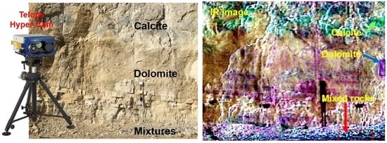
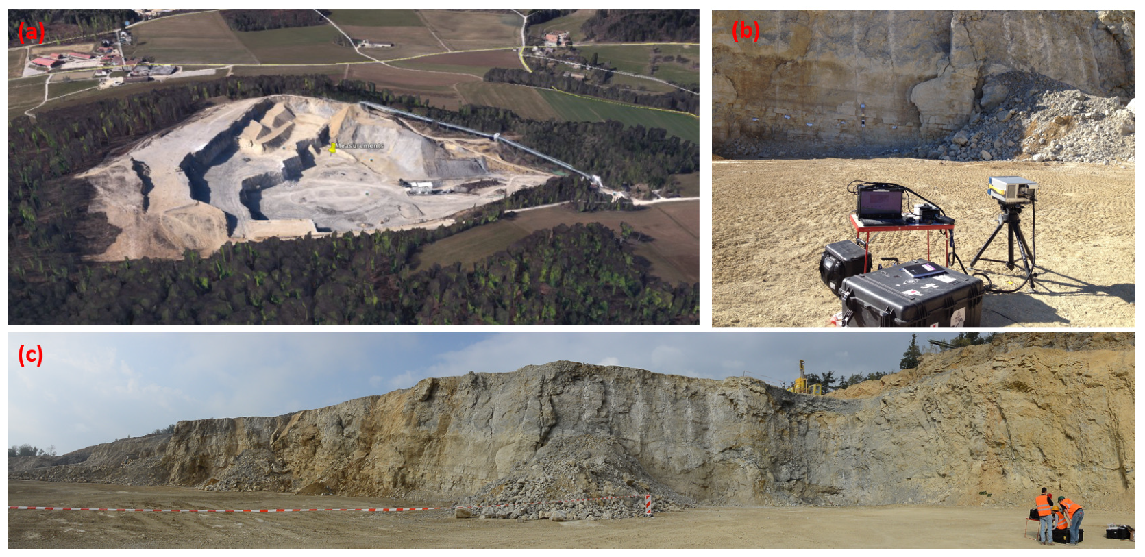
2. Description of the Study Area

The experiments were carried out in a Jura Cement quarry (http://www.juracement.ch/) at Cornaux (47 deg 2 min 20 s N; 7 deg 25 min E, Switzerland). Figure 1 depicts an overview of the open mine (Figure 1a), the Telops hyperspectral camera (Hyper-Cam) (Figure 1b) and photographs of the vertical cliffs (Figure 1c). The Cornaux limestone mine, operated by Jura Cement, is a source of calcite for cement manufacturing. Carbonate rocks or limestone are sedimentary rocks, mostly consisting of calcite (CaCO 3 ) and dolomite (CaMg(CO 3 ) 2 ). In nature, carbonate minerals exist in different various chemical compositions such as siderite (FeCO 3 ), magnesite (MgCO 3 ), aragonite (CaCO 3 ), ankerite (CaFe(CO 3 ) 2 ), rhodochrosite (MnCO 3 ), strontianite (SrCO 3 ), cerussite (PbCO 3 ), witherite (BaCO 3 ), malachite (Cu 2 CO 3 (OH) 2 ) and azurite (Cu 2 (CO 3 ) 2 (OH) 2 ) [32,33,34,35,36]. However, the major carbonate minerals expected at the Cornaux limestone quarry are calcite and dolomite. The presence of other carbonate forms was also investigated using LWIR spectroscopy to evaluate the ability of the Hyper-Cam to differentiate between different carbonate compositions.

3. Background to LWIR Carbonate Spectroscopy

The fundamental vibration modes of a free carbonate ion (CO 3 2 + ) [37] are shown in Table 1. A carbonate ion consists of four atoms leading to six possible fundamental vibration modes. The asymmetric stretch at 6.99 μ m ( ν 3 ) and the asymmetric in-plane bend at 13.98 μ m ( ν 4 ) are doubly degenerated (two vibrations with the same frequencies). If the ν 3 falls within a low atmospheric transmission window, the other modes give pronounced absorption bands within the TIR region. The exact position of the absorption band centre depends on the metal ions connected to the carbonate ligand. Calcite (CaCO 3 ) and dolomite (CaMg(CO 3 ) 2 ) can for example be distinguished due to a slight shifting of the carbonate absorption features. In this work, the spectral behaviour of the carbonate minerals was used to construct the lithological map of the investigated outcrop.

4. Data and Methodology

4.1. Instrumentation

The Telops passive thermal infrared hyperspectral research instrument used for field measurements in this work (see Figure 1b) is a lightweight and compact system suitable for ground-based experiments (www.telops.com). The Hyper-Cam includes a Fourier Transform Infrared (FT-IR) spectrometer that provides high spectral resolution and a closed cycle Stirling cooled Focal Plane Array (FPA) detector of 320 × 256 pixels over a basic 6.4° × 5.1° field of view (FOV). The spectral resolution is user-selectable from 0.25 cm 1 –150 cm 1 (2.5 nm–1.5 μ m at 10 μ m and 1.5 nm–890 nm at 7.7 μ m) over the 1300 cm 1 –855 cm 1 (7.7 μ m–11.8 μ m) spectral ranges with up to 1600 channels, suitable in many geological remote sensing applications for detailed analysis of the absorption features. The instrument also includes a GPS and is equipped with a high resolution digital camera. Visible images are simultaneously recorded along with the infrared hyperspectral images (datacubes) and the GPS positions of experimental locations. For field applications, the instrument can be powered by truck batteries with an inverter, and the power consumption is 250 W peak and 170 W in steady state.
Three other laboratory-based instruments (X-ray diffractometer, MiDACemission and the Bruker LWIR spectrometers) were also applied at ITC-University of Twente, for the detailed LWIR spectroscopy and identification of the mineral species on 33 samples from Cornaux during this survey study campaign. The result of this analysis will be presented in a follow-up paper. The ASD contact probe spectrometer was used to measure some VNIR-SWIR spectra at different locations of the vertical walls.

4.2. Experimental Setup

For our experiments, the spectral resolution was set to 4 cm 1 (which represents a bandwidth of about 40 nm at 10 μ m) with an integration time of about 215 μ s. In order to improve the signal to noise ratio, about 20 datacubes were recorded per scene, and an acquisition time of 9 s per datacube was used. The data transfer between the Hyper-Cam and a standard desktop was done using full camera link connection. A de-magnifying 0.25× telescope (or field of view expander) was used, resulting in an extended FOV of 25.6° × 20.4°. The sensor was located at a 35-m distance from the vertical cliff, leading to an effective pixel size of about 26 cm 2 /pixel. To facilitate the data analysis, two reference plates (infragold and blackbody) were introduced in the investigated scenes (see Figure 2a). The infragold plate exhibits excellent reflectance properties with a constant emissivity value ( ϵ ≈ 0.1) over the 7.7 μ m–11.8 μ m spectral range. This emissivity was used to estimate the incident radiance (or downwelling radiance) from infragold represented image pixels, since it reflects most of the incident radiation. The blackbody plate exhibits a rather high and constant emissivity ( ϵ ≈ 0.9) behaviour over the instrument spectral range. The signal measured on this blackbody plate at the sensor position is used to estimate the atmospheric transmittance between the Hyper-Cam and the investigated mine face.

4.3. Data Processing

The raw datacubes contain one interferogram per pixel, which have been recorded simultaneously on the FPA by the Hyper-Cam. Fast Fourier transform is then performed to get spectroscopic information on each pixel. Automated radiometric calibration is performed on the raw (in digital numbers) datacubes using two integrated blackbodies with different temperatures. For the experiments reported in this paper, the blackbodies were set to 20 °C and to 40 °C, and the spectral radiance (calibrated data) and the raw data were saved as output data. We used the averaged spectral radiance data (over 20 acquisitions) with a noise equivalent spectral radiance of about 57 nW/cm 2 .sr.cm 1 to conduct Temperature Emissivity Separation (TES). The retrieval of emissivity spectra is the final goal of the data processing chart, as emissivity is related to the material inherent composition. Spectral unmixing of the emissivity data was then carried out using the spectral signatures of selected minerals obtained from spectral libraries such as ECOSTRESS [38].

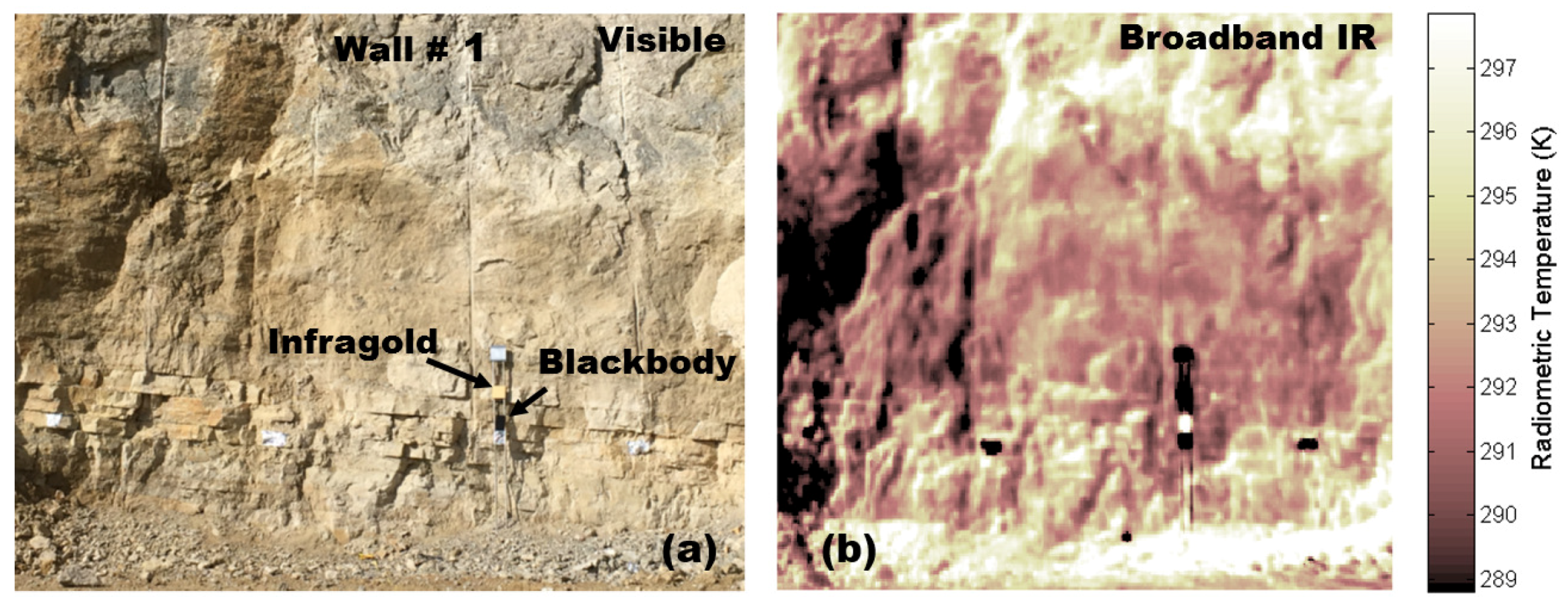
4.4. Temperature and Emissivity Calculation.
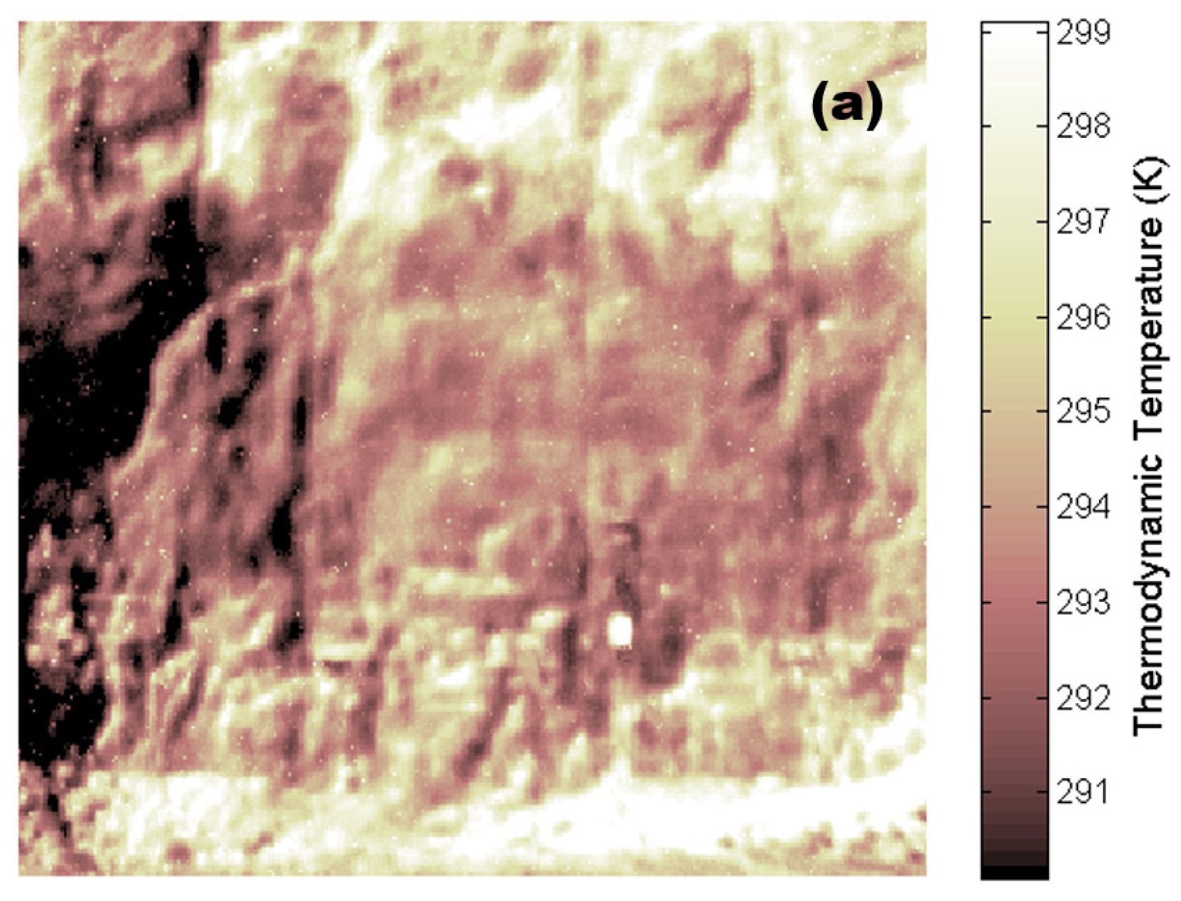
Unlike a blackbody, the rocks present in the investigated scene selectively absorb/emit the incident energy as a function of wavelength. The ratio of their radiated energy to that radiated by a blackbody at the same wavelength and temperature is called the spectral emissivity. Analogous to spectral reflectivity in the VNIR-SWIR wavelength region, spectral emissivity describes the materials’ inherent characteristics in the TIR. The spectral emissivity is, together with the thermodynamic temperature, among the fundamental parameters needed to be derived from the spectral radiance datacube, in order to characterize the hyperspectral TIR remote sensing data fully. In practice, the thermodynamic temperature of the investigated target must be known or assumed in order to calculate its spectral emissivity. Temperature emissivity separation procedures are therefore commonly conducted on the measured TIR hyperspectral data to retrieve the thermodynamic temperature and spectral emissivity maps of the investigated scene separately with the following equation.
L ( T , λ ) = ( L t ( T , λ ) ϵ ( λ ) + D w ( λ ) [ 1 ϵ ( λ ) ] ) τ a t m ( λ ) + [ 1 τ a t m ( λ ) ] L a t m ( T , λ )
We conducted TES by solving Equation (1) where L(T, λ ) is the at-sensor radiance, ϵ ( λ ) the target’s spectral emissivity, D w the effective downwelling radiance upon the target, L t (T, λ ) the target’s self-emission (which is a function of its thermodynamic temperature as described by the Planck equation), τ a t m ( λ ) is the atmospheric transmittance between the target and sensor, L a t m (T, λ ) the radiance associated with TIR self-emission of all atmospheric components, T is the thermodynamic temperature and λ is the wavelength.
Different methods are commonly used to conduct TES such as: reference channel [39], blackbody fit [40], maximum spectral temperature [40] and spectral smoothing [40,41,42]. Within the reference channel methods, assumptions are made that the emissivity is ϵ = 1 for some wavelengths in the spectral region under consideration. The temperature at those wavelengths is then calculated along with the emissivity for the rest of the spectra. However, no realistic material has an emissivity of ϵ = 1 at any wavelength; therefore, this approach usually results in a shift upward of the calculated data. Unless the maximum emissivity of a specific material in the investigated scene is known, the outputs of this method will never be absolute [40].
In this work, we used reference plates in the investigated scene, which were placed at the mine face (Figure 2), to facilitate the solving of the radiative transfer model. By using the radiance measured at the sensor level with the blackbody (L 1 ) or infragold (L 2 ) plate as a target, knowing the temperatures of the plates and the atmospheric temperature, we calculate the atmospheric transmittance and the downwelling radiance as described in the above Experimental Setup Section as follows:
τ a t m = L 1 L a t m L B B ϵ 1 + D w ( 1 ϵ 1 ) L a t m
D w = L 2 ( 1 τ a t m ) L a t m L I G τ a t m ϵ 2 ( 1 ϵ 2 ) τ a t m
where L B B and L I G are the blackbody and infragold self-emission described by the Planck equation and ϵ 1 and ϵ 2 are their respective emissivities. We therefore solve Equation (1) for all the image pixels of the investigated scene using the τ a t m obtained on the blackbody plate and D w obtained on the infragold plate. We also used another different TES algorithm that implements an in-scene atmospheric correction using the calculation of Equation (1) with MODTRAN [43] to correct for downwelling radiance, and the results were similar to those presented in this paper.

5. Results

Hyperspectral imaging of two vertical walls in the open mine were conducted with the main objective of characterizing the mineralogy distribution of the mine. Figure 2 shows a photograph of one of the walls referred to as Wall #1 in this paper (Figure 2a). A typical broadband infrared image associated with the hyperspectral data is shown in Figure 2b. This temperature map was obtained first by converting the calibrated spectral radiance datacube into the brightness temperature datacube using an inverted Planck function for each wavenumber. The wavelength dependency was then removed by computing within the brightness temperature datacube, the mean value of all wavenumbers data at each pixel. We observed large variations of radiometric temperature (about 13 K), most likely caused by emissivity and/or thermodynamic temperature differences of the rocks and other elements in the investigated scene. It should also be noted that during the surveying, some of the mine face areas were damp and therefore likely to have an evaporative cooling effect, as well as a blackbody moisture response. Moisture significantly affects the TIR remote sensing experiments, leading to an overestimation of the thermodynamic temperature and a shift upward of the emissivity values. Measurements of the humidity of the different elements in the investigated scene (when possible) were sometimes needed to correct its contribution. The radiometric temperature map obtained by summing over the all spectral range of the detector was similar to the data one could get from a simple broadband infrared camera. However, the spectroscopic information and geochemical distribution of the mineralogy and lithology cannot be extracted from this type of broadband image. We therefore analysed the wavelength-dependent data.
The thermodynamic temperature map obtained from TES calculations is shown in Figure 3a. We obtained, as previously reported [28], higher values of temperature than their corresponding brightness temperature. This is expected since the downwelling and atmospheric contribution have been addressed in the TES calculation procedure. When comparing the two temperature maps (Figure 2b and Figure 3a), one can clearly see that the temperature differences of the rocks (and the other elements in the investigated wall) show a higher contribution in the thermal contrast observed in Figure 2b as compared to their emissivity variation. Nevertheless, in the emissivity maps depicted in Figure 3b ( λ = 11.2 μ m) and Figure 3c ( λ = 11.3 μ m), clear spectral dependence can be seen on the outcrop. Those emissivity maps highlight the spectral contrast associated with the geochemical distribution of the mineralogy within the carbonate mine face.
The spectral emissivity of seven selected locations (one-pixel size) on Wall #1 are shown in Figure 4a. Their positions relative to the whole investigated cliff are labelled in Figure 3b. Clear location-dependent spectral variations can be seen, most likely related to the geochemical distribution of the mineralogy of the cliff. The narrow spectral feature observed in all pixel locations around 850–925 cm 1 (11.765–10.811 μ m) and the broader feature observed in Pixel #1 and Pixel #2 around 950–1150 cm 1 (10.526–8.696 μ m) are likely associated with carbonate minerals. The series of sharp peaks in the 1200–1300 cm 1 (8.333–7.692 μ m) spectral range is associated with atmospheric absorption (water vapour).

6. Discussion

In order to estimate the carbonate mineralogy composition of the mine face, the TIR spectral emissivity data derived from measurements with the Telops Hyper-Cam (Figure 4a) were compared to the library’s reference spectral emissivity data of different carbonate minerals. The carbonate minerals likely to be present in the mine face are calcite and dolomite. However, for the spectral library matching approach used in this work, we included other carbonate minerals (malachite, azurite, smithsonite, siderite, rhodochrosite and magnesite), as they present strong emissivity spectral features in the same spectral regions as observed in the experiments: 850–925 cm 1 (11.765–10.811 μ m) and 950–1150 cm 1 (10.526–8.696 μ m) (see Figure 4a,b). Longwave infrared spectral signatures of carbonates can also be found in [44]. The ECOSTRESS spectral library database [38] (previously known as the ASTER library) was used for the identification. The VNIR-SWIR ASD contact probe spectra measured at random positions of the mine face depicted in Figure 4c were also used for identification of the mineralogy and comparing the results obtained in the TIR region. The measured VNIR-SWIR reflectance spectra were compared to reference reflectance spectra (from the ECOSTRESS spectral library database) of calcite, dolomite and other carbonate minerals having reflectance spectral features in the same bands with the measured spectra: magnesite, smithsonite, siderite, rhodochrosite (Figure 4d). We also conducted XRD analysis to complement this work and extend the mineralogy identification to possible non-carbonate mineral constituents that will be presented in a follow-up paper.
Each spectrum obtained on the seven locations depicted in Figure 4a contains a continuum component and individual features. The continuum is the background that can be determined by fitting a convex envelope connecting local maxima. The spectrum can then be normalized in order to remove the continuum component. Spectral feature fitting approaches and comparison of measured spectra with library spectra are based on continuum removed pixel spectra [45,46]. We performed detailed analysis of absorption features, such as the determination of the position, the absorption depth and Full Width at Half Maximum (FWHM), using continuum removed spectra. The tables below summarize the wavenumber positions, the FWHM and the depth of the emissivity peaks of the seven selected locations of the cliff (Table 2) and that of the relevant reference carbonate minerals (Figure 4b) in the TIR region (Table 3).
Semi-quantitative analysis of the mineral abundances was carried out from the measured spectra by analysing the intensity of the emissivity spectral bands [47]. In some cases, some minerals dominate the spectra measured on a pixel location and hamper the identification of other constituent minerals that have less pronounced emissivity properties. However, generally, a mineral with a unique emissivity signature can be correlated to a specific lithological unit, which can be used to trace and map the lithology. The locations associated with Pixels #1 and #2 appear to have similar mineralogy content, most likely calcite, although the spectral features also suggest the unlikely Cu-bearing malachite and azurite carbonate forms. The emissivity spectra obtained at the location of Pixel #3 clearly matches the spectrum of pure dolomite. On the contrary, the locations of Pixels #4, #5 and #6 situated on the ground level of the vertical cliff show relatively broader spectra resulting from a mixture of calcite and dolomite as major minerals. Finally, the location of Pixel #7 shows a weak absorption peak around 892.48 cm 1 , most likely indicating the presence of dolomite, though the spectral feature obtained there is not very pronounced. The smithsonite, siderite, rhodochrosite and magnesite minerals are unlikely to be present within the investigated scene since their spectral features at 876.17 cm 1 (11,413.31 nm), 875.88 cm 1 (11,417.09 nm), 875.01 cm 1 (11,428.44 nm) and 906.03 cm 1 (11,037.16 nm), respectively, are approximately 10 cm 1 offsets from the closest and the farthest spectral absorption feature observed in the measured TIR spectra.
The spectral curves obtained from geological outcrops are generally influenced by mineralogy mixture, particle size, view and surface roughness. The depth of the spectral feature indicates the amount of light absorbed by the mineral and is therefore related to the mineral abundance [47,48]. By comparing the depths of the two features of the emissivity spectra related to the locations of Pixels #1 and #2 (Table 2), we identify calcite as the more abundant mineral on those locations. The depths of the emissivity spectral features observed on the locations of Pixels #4, #5 and #6 are larger than that of pure dolomite observed on Pixel #3, most likely due to the fact that the former are composed of mixed rocks or solid solution series [44].
The spectral library matching approach was also used on the VNIR-SWIR spectra measured at random spots of the open mine pit with the ASD contact probe spectrometer (Figure 4c). The comparison of measured VNIR-SWIR spectra with the reference spectra of the ASTER library (Figure 4d) indicates the presence of a dolomite-calcite (and possible magnesite) mix at the mine face. However, more accurate XRD analysis (results will be presented in a follow-up paper) only identifies calcite and dolomite. The mineral identification from VNIR-SWIR and LWIR is very consistent; nevertheless, the discrimination of the different carbonate spectral signatures was better in the LWIR compared to VNIR-SWIR.
In remote sensing, spectral mixtures can be found in four different types: molecular mixture, linear, intimate and mixture due to coating [47]. The spectrum of optically separated rocks not subjected to multiple scattering between them is usually of a linear mixture type also referred to as a spatial mixture. The spectrum resulting from the intimate type of mixture is a complex non-linear combination of spectra due to multiple scattering between rocks that are in intimate contact. A molecular mixture usually results in band shifts that occur when molecules are mixed together. Finally, when a rock is coated with different layers of different optical thicknesses, each layer acts as an independent scatterer, and the resulting signal is a spectral mixture due to coating. In this work, optical separation of different rocks can be assumed; therefore, since the spectrum of each mineral, also named as an end-member spectrum, is known, the fraction of each component present in a pixel can be determined by linear spectral unmixing algorithms [28,49,50].
Figure 5a depicts the spectral mineral map of Wall #1 of the investigated outcrop visualized in RGB with red, green and blue associated with the following spectral bands (in cm 1 ) B = [869–879], R = [879–889], G = [889–900]. Our data show the top side of the wall is dominantly composed of calcite. By comparing this spectral mineral map and the photograph shown in Figure 2a, good coincidence can be seen between grey-darkish-coloured rocks on the top part of the wall in the visible image and the calcite distribution in the lithography map. The middle part of the wall appears to be composed of dolomite, while the rocks near the ground level are mainly a mix of calcite and dolomite, resulting from the combined fallen debris at the base of the mine face. The other areas correspond to unstructured emissivity or undetermined components.
The spatial average spectral emissivity on three regions where calcite, dolomite and mixtures are located is shown in Figure 5b. Calcite appears to be more abundant in the mixture in the selected region (shown with red marked). The reference spectral emissivity of the calcite and dolomite obtained from the library database [38] is depicted in Figure 5c. One can see a good match between the measured spectra and the position of absorption peaks of the library spectral emissivity.
The data collected on the second wall of the investigated outcrop shown in Figure 6 are consistent with the results obtained on the first wall. The relative position of the two walls can be seen on the panoramic photograph depicted in Figure 6a. A visible image of Wall #2 obtained with the Hyper-Cam high resolution digital camera is shown in Figure 6b. The spectral mineral map of this wall (Figure 6c) shows dolomite near the ground level. The calcite is mainly present in the regions of the wall where the rocks appear to be darker compared to the lighter dolomite-bearing regions, consistent with the observations of Wall #1. The averaged spectral emissivity on dolomite, calcite and mixture regions (Figure 6d) shows a slope (continuum component) distortion most likely associated with stronger atmospheric absorption feature as compared to Figure 5b; see the water absorption lines around 1200–1300 cm 1 (8.333–7.692 μ m) in the two figures. Indeed, the data of the two walls were collected on two different days, which mirrored the two different atmospheric conditions.

7. Conclusions

We have demonstrated that field-based TIR hyperspectral technology, integrated with visible photographs, enables an efficient mapping of mineralogy and, therefore, lithology. This technique offers a significantly improved interpretation of mine face composition, normally difficult to observe and quantify with conventional mapping methods. Temperature emissivity separation was successfully conducted on hyperspectral data of a carbonate mine face exposure obtained using Telops Hyper-Cam. Spectral emissivity unmixing was then carried out on the obtained datacube signatures assuming known geological components expected to be found in the quarry. This resulted in an improved qualitative and quantitative analysis of the geochemical properties of the mine face, useful for quality control of its feedstock. The carbonate mineralogical maps obtained are consistent with the variation within the Jura Cement Limestone Quarry. The obtained end-member spectra are in agreement with published spectral libraries for carbonate. The high spectral and spatial resolution of the Telops Hyper-Cam spectrally resolves very similar minerals and gives highly detailed mineralogical maps. Our results highlight the benefits of this type of lightweight hyperspectral instrument for routine field applications such as in mining, engineering, forestry or archaeology, where the spatial analysis of mineral and chemical distribution is essential.

Author Contributions

Writing, original draft: S.B.-T.; Writing, review and editing: all authors; A.H., I.V., C.V., A.E. and R.H. performed the experiments; S.B.-T., A.H. and M.C. analyzed the results; and all authors discussed the interpretation of the experimental results.

Funding

This research was funded by Jura Cement, co-author of the paper.

Acknowledgments

We would like to thank Jura Cement for administrative and technical support and especially Christophe Veuve and Marcel Bieri, who made it possible to run this measurement campaign in their open mine.

Conflicts of Interest

The authors declare no conflicts of interest.

References

  1. Axelsson, P. Processing of laser scanner data—Algorithms and applications. ISPRS J. Photogramm. Remote Sens. 1999, 54, 138–147. [Google Scholar] [CrossRef]
  2. Fröhlich, C.; Mettenleiter, M. Terrestrial laser scanning—New perspectives in 3D surveying. Int. Arch. Photogramm. Remote Sens. Spat. Inf. Sci. 2004, 36, W2. [Google Scholar]
  3. Slob, S.; Hack, R. 3D terrestrial laser scanning as a new field measurement and monitoring technique. In Engineering Geology for Infrastructure Planning in Europe; Springer: New York, NY, USA, 2004; pp. 179–189. [Google Scholar]
  4. Buckley, S.J.; Howell, J.; Enge, H.; Kurz, T. Terrestrial laser scanning in geology: Data acquisition, processing and accuracy considerations. J. Geol. Soc. 2008, 165, 625–638. [Google Scholar] [CrossRef]
  5. Bellian, J.A.; Kerans, C.; Jennette, D.C. Digital outcrop models: Applications of terrestrial scanning LiDAR technology in stratigraphic modeling. J. Sediment. Res. 2005, 75, 166–176. [Google Scholar] [CrossRef]
  6. McCaffrey, K.; Jones, R.; Holdsworth, R.; Wilson, R.; Clegg, P.; Imber, J.; Holliman, N.; Trinks, I. Unlocking the spatial dimension: Digital technologies and the future of geoscience fieldwork. J. Geol. Soc. 2005, 162, 927–938. [Google Scholar] [CrossRef]
  7. Debba, P.; Carranza, E.J.; Stein, A.; van der Meer, F.D. Deriving optimal exploration target zones on mineral prospectivity maps. Math. Geosci. 2009, 41, 421. [Google Scholar] [CrossRef]
  8. Catani, F.; Farina, P.; Moretti, S.; Nico, G.; Strozzi, T. On the application of SAR interferometry to geomorphological studies: Estimation of landform attributes and mass movements. Geomorphology 2005, 66, 119–131. [Google Scholar] [CrossRef]
  9. Smith, M.; Rose, J.; Booth, S. Geomorphological mapping of glacial landforms from remotely sensed data: An evaluation of the principal data sources and an assessment of their quality. Geomorphology 2006, 76, 148–165. [Google Scholar] [CrossRef]
  10. Bishop, M.P.; Shroder, J.F., Jr.; Colby, J.D. Remote sensing and geomorphometry for studying relief production in high mountains. Geomorphology 2003, 55, 345–361. [Google Scholar] [CrossRef]
  11. Berger, Z. Satellite Hydrocarbon Exploration: Interpretation and Integration Techniques; Springer: New York, NY, USA, 2012. [Google Scholar]
  12. Fialko, Y.; Simons, M.; Agnew, D. The complete (3-D) surface displacement field in the epicentral area of the 1999 Mw7. 1 Hector Mine earthquake, California, from space geodetic observations. Geophys. Res. Lett. 2001, 28, 3063–3066. [Google Scholar] [CrossRef]
  13. Werner, C.; Wegmuller, U.; Strozzi, T.; Wiesmann, A. Interferometric point target analysis for deformation mapping. In Proceedings of the 2003 IEEE International Geoscience and Remote Sensing Symposium, IGARSS’03, Toulouse, France, 21–25 July 2003; Volume 7, pp. 4362–4364. [Google Scholar]
  14. Amelung, F.; Galloway, D.L.; Bell, J.W.; Zebker, H.A.; Laczniak, R.J. Sensing the ups and downs of Las Vegas: InSAR reveals structural control of land subsidence and aquifer-system deformation. Geology 1999, 27, 483–486. [Google Scholar] [CrossRef]
  15. Van derWerff, H.; Van der Meijde, M.; Jansma, F.; Van der Meer, F.; Groothuis, G.J. A spatial-spectral approach for visualization of vegetation stress resulting from pipeline leakage. Sensors 2008, 8, 3733–3743. [Google Scholar] [CrossRef] [PubMed]
  16. Sabins, F.F. Remote sensing for mineral exploration. Ore Geol. Rev. 1999, 14, 157–183. [Google Scholar] [CrossRef]
  17. Roonwal, G. Remote Sensing in Mineral Exploration. In Mineral Exploration: Practical Application; Springer: New York, NY, USA, 2018; pp. 119–153. [Google Scholar]
  18. Hunt, G.R. Electromagnetic radiation: The communication link in remote sensing. In Remote Sensing in Geololgy, 3rd ed.; Wiely: New York, NY, USA, 1980; pp. 5–45. [Google Scholar]
  19. Al Fasatwi, Y.; Van Dijk, P. Lineament and geomorphic analysis of remote sensing data as an aid to hydrocarbon exploration, Sirt Basin, Libya. ITC J. 1990, 2, 137–144. [Google Scholar]
  20. Ellingsrud, S.; Eidesmo, T.; Johansen, S.; Sinha, M.; MacGregor, L.; Constable, S. Remote sensing of hydrocarbon layers by seabed logging (SBL): Results from a cruise offshore Angola. Lead. Edge 2002, 21, 972–982. [Google Scholar] [CrossRef]
  21. Khan, S.D.; Jacobson, S. Remote sensing and geochemistry for detecting hydrocarbon microseepages. Geol. Soc. Am. Bull. 2008, 120, 96–105. [Google Scholar] [CrossRef]
  22. Clark, R.N.; King, T.V.; Klejwa, M.; Swayze, G.A.; Vergo, N. High spectral resolution reflectance spectroscopy of minerals. J. Geophys. Res. Solid Earth 1990, 95, 12653–12680. [Google Scholar] [CrossRef]
  23. Weng, Q. Thermal infrared remote sensing for urban climate and environmental studies: Methods, applications, and trends. ISPRS J. Photogramm. Remote Sens. 2009, 64, 335–344. [Google Scholar] [CrossRef]
  24. Lefsky, M.A.; Cohen, W.B.; Parker, G.G.; Harding, D.J. Lidar remote sensing for ecosystem studies: Lidar, an emerging remote sensing technology that directly measures the three-dimensional distribution of plant canopies, can accurately estimate vegetation structural attributes and should be of particular interest to forest, landscape, and global ecologists. AIBS Bull. 2002, 52, 19–30. [Google Scholar]
  25. Goetz, A.F.; Vane, G.; Solomon, J.E.; Rock, B.N. Imaging spectrometry for earth remote sensing. Science 1985, 228, 1147–1153. [Google Scholar] [CrossRef] [PubMed]
  26. Bowen, B.B.; Martini, B.A.; Chan, M.A.; Parry, W.T. Reflectance spectroscopic mapping of diagenetic heterogeneities and fluid-flow pathways in the Jurassic Navajo Sandstone. AAPG Bull. 2007, 91, 173–190. [Google Scholar] [CrossRef]
  27. Harris, J.; Rogge, D.; Hitchcock, R.; Ijewliw, O.; Wright, D. Mapping lithology in Canada’s Arctic: Application of hyperspectral data using the minimum noise fraction transformation and matched filtering. Can. J. Earth Sci. 2005, 42, 2173–2193. [Google Scholar] [CrossRef]
  28. Gagnon, M.A.; Tremblay, P.; Savary, S.; Duval, M.; Farley, V.; Lagueux, P.; Guyot, É.; Chamberland, M. Airborne thermal infrared hyperspectral imaging for mineral mapping. In Proceedings of the International Workshop on Advanced Infrared Technology & Applications, Pisa, Italy, 29 September–2 October 2015; Volume 29, pp. 83–86. [Google Scholar]
  29. Hapke, B. Theory of Reflectance and Emittance Spectroscopy; Cambridge University Press: Cambridge, UK, 2012. [Google Scholar]
  30. Gillespie, A.R.; Rokugawa, S.; Hook, S.J.; Matsunaga, T.; Kahle, A.B. Temperature/Emissivity Separation Algorithm Theoretical Basis Document, Version 2.4; ATBD Contract NAS5-31372; NASA: Greenbelt, Maryland, 1999. [Google Scholar]
  31. Lutgens, F.K.; Tarbuck, E.J.; Tasa, D.G. Essentials of Geology; Pearson Higher Education: San Francisco, CA, USA, 2014. [Google Scholar]
  32. Hatch, F.H.; Rastall, R.H.; Greensmith, J.T. Textbook of Petrology V2: The Petrology of the Sedimentary Rocks; Allen & Unwin: Boston, MA, USA, 1971. [Google Scholar]
  33. Bissell, H.J.; Chilingar, G.V. Classification of sedimentary carbonate rocks. In Developments in Sedimentology; Elsevier: Amsterdam, The Netherlands, 1967; Volume 9, pp. 87–168. [Google Scholar]
  34. Hunt, G.R.; Salisbury, J.W. Visible and near infrared spectra of minerals and rocks. II. Carbonates. Mod. Geol. 1971, 2, 23–30. [Google Scholar]
  35. Dietrich, R.V.; Skinner, B.J. Rocks and Rock Minerals; Technical Report; Wiley: New York, NY, USA, 1979. [Google Scholar]
  36. Hamilton, W.; Bishop, A.; Woolley, A. Minerals, Rocks and Fossils; Hamlyn Publishing Group: London, UK, 1987. [Google Scholar]
  37. Lane, M.D.; Christensen, P.R. Thermal infrared emission spectroscopy of anhydrous carbonates. J. Geophys. Res. 1997, 102, 25581–25592. [Google Scholar] [CrossRef] [Green Version]
  38. Baldridge, A.; Hook, S.; Grove, C.; Rivera, G. The ASTER spectral library version 2.0. Remote Sens. Environ. 2009, 113, 711–715. [Google Scholar] [CrossRef]
  39. Kahle, A.B.; Alley, R.E. Separation of temperature and emittance in remotely sensed radiance measurements. Remote Sens. Environ. 1992, 42, 107–111. [Google Scholar] [CrossRef]
  40. Salvaggio, C.; Miller, C.J. Comparison of field-and laboratory-collected midwave and longwave infrared emissivity spectra/data reduction techniques. In Algorithms for Multispectral, Hyperspectral, and Ultraspectral Imagery VII International Society for Optics and Photonics; SPIE: Bellingham, WA, USA, 2001; Volume 4381, pp. 549–559. [Google Scholar]
  41. Horton, K.A.; Johnson, J.R.; Lucey, P.G. Infrared measurements of pristine and disturbed soils 2. Environmental effects and field data reduction. Remote Sens. Environ. 1998, 64, 47–52. [Google Scholar] [CrossRef]
  42. Bower, N.; Knuteson, R.; Revercomb, H. High Spectral Resolution Land Surface Temperature and Emissivity Measurements in the Thermal Infrared; Co-operative Institute for Meteorological and Satellite Studies at the University of Wisconsin: Madison, WI, USA, 1999. [Google Scholar]
  43. Berk, A.; Conforti, P.; Kennett, R.; Perkins, T.; Hawes, F.; van den Bosch, J. MODTRAN® 6: A major upgrade of the MODTRAN® radiative transfer code. In Proceedings of the 2014 6th Workshop on IEEE Hyperspectral Image and Signal Processing: Evolution in Remote Sensing (WHISPERS), Zurich, Switzerland, 24–27 June 2014; pp. 1–4. [Google Scholar]
  44. Green, D.; Schodlok, M. Characterisation of carbonate minerals from hyperspectral TIR scanning using features at 14,000 and 11,300 nm. Aust. J. Earth Sci. 2016, 63, 951–957. [Google Scholar]
  45. Clark, R.; Swayze, G.; Gallagher, A.; Gorelick, N.; Kruse, F. Mapping with imaging spectrometer data using the complete band shape least-squares algorithm simultaneously fit to multiple spectral features from multiple materials. In Proceedings of the Third Airborne Visible/Infrared Imaging Spectrometer (AVIRIS) Workshop; JPL Publication 91-28; Jet Propulsion Laboratory: Pasadena, CA, USA, 1991; Volume 42, pp. 2–3. [Google Scholar]
  46. Clark, R.N.; Swayze, G.A.; Livo, K.E.; Kokaly, R.F.; Sutley, S.J.; Dalton, J.B.; McDougal, R.R.; Gent, C.A. Imaging spectroscopy: Earth and planetary remote sensing with the USGS Tetracorder and expert systems. J. Geophys. Res. 2003, 108, 44. [Google Scholar] [CrossRef]
  47. Clark, R.N. Spectroscopy of rocks and minerals, and principles of spectroscopy. Manu. Remote Sens. 1999, 3, 2. [Google Scholar]
  48. Clark, R.N.; Roush, T.L. Reflectance spectroscopy: Quantitative analysis techniques for remote sensing applications. J. Geophys. Res. Solid Earth 1984, 89, 6329–6340. [Google Scholar] [CrossRef]
  49. Adams, J.B. Imaging spectroscopy: Interpretation based on spectral mixture analysis. In Remote Geochemical Analysis: Elemental and Mineralogical Composition; Cambridge University Press: Cambridge, UK, 1993; pp. 145–166. [Google Scholar]
  50. Ichoku, C.; Karnieli, A. A review of mixture modeling techniques for sub-pixel land cover estimation. Remote Sens. Rev. 1996, 13, 161–186. [Google Scholar] [CrossRef]
Figure 1. (a) Overview of the Jura Cement quarry; (b) the ground-based Telops Hyper-Cam instrument; and (c) photograph of the vertical cliffs.
Remotesensing 10 01518 g001
Figure 2. Photograph (a) and broadband infrared image (b) of Wall #1 obtained with the Telops Hyper-Cam. We intentionally placed blackbody and infragold plates on the investigated wall to facilitate the calculations of temperature-emissivity separation. The infrared image represents a portion of the wall of about 13 m (vertical) by 16 m (horizontal).
Remotesensing 10 01518 g002
Figure 3. Thermodynamic temperature (a) and emissivity maps of Wall #1 of the investigated outcrop at λ = 11.2 μ m (b) and λ = 11.3 μ m (c) obtained after performing temperature-emissivity separation. Seven selected locations (of one-pixel size) marked with cross mark X 1 (upper left of the seven X-marks with numbers proceeding as 1–7 in a clock-wise direction) on (b) are discussed later below. The images represent a portion of the wall of about 13 m (vertical) by 16 m (horizontal).
Remotesensing 10 01518 g003aRemotesensing 10 01518 g003b
Figure 4. (a) The LWIR spectral emissivity of seven selected locations in the vertical cliff and (b) the LWIR reference spectra of different carbonate minerals obtained from the ECOSTRESS spectral library database [38]. The VNIR-SWIR ASDcontact probe spectra measured at random positions of the mine face (c) and VNIR-SWIR reference spectra of different carbonate minerals obtained from the ECOSTRESS spectral library database (d).
Remotesensing 10 01518 g004
Figure 5. (a) Spectral mineral map of Wall #1 of the investigated outcrop in RGB with red, green and blue associated with the following spectral bands (in cm 1 ) B = [869–879], R = [879–889], G = [889–900]; (b) averaged spectral emissivity on three different regions of the wall; (c) the reference spectral emissivity of calcite and dolomite obtained from the library database [38].
Remotesensing 10 01518 g005
Figure 6. (a) Photograph of the investigated outcrop showing the two walls of vertical cliff studied in this work; (b) image of Wall #2 obtained with the Telops Hyper-Cam high resolution visible digital camera; (c) spectral mineral map of Wall #2 of the investigated outcrop in RGB with red, green and blue associated with the following spectral bands (in cm 1 ) B = [869–879], R = [879–889], G = [889–900]; (d) averaged spectral emissivity on three different regions of the wall.
Remotesensing 10 01518 g006
Table 1. Illustration of fundamental vibration modes of a free carbonate ion with motion vectors.
Remotesensing 10 01518 i001 Remotesensing 10 01518 i002 Remotesensing 10 01518 i003 Remotesensing 10 01518 i004
λ = 9.25 μ m (1080 cm 1 ) λ = 11.36 μ m (880 cm 1 ) λ = 6.99 μ m (1430 cm 1 ) λ = 13.98 μ m (715 cm 1 )
NondegenerateNondegenerate symmetricDoubly degenerateDoubly degenerate
symmetric stretchout-of-plane bendasymmetric stretchasymmetric in-plane bend
Table 2. Positions, FWHM and depth of the emissivity absorption features shown in Figure 4a representing the seven selected locations in the investigated cliff.
Pixel1/ λ 1 (cm 1 )FWHM 1 (cm 1 )Depth 1 1/ λ 2 (cm 1 )FWHM 2 (cm 1 )Depth 2
#1885.62 ± 0.8617.75 ± 4.010.0921033.16 ± 1.41140.82 ± 13.030.064
#2884.45 ± 0.7814.56 ± 3.650.0961033.44 ± 2.0374.57 ± 9.270.059
#3895.35 ± 0.6618.11 ± 3.090.082
#4887.47 ± 0.6547.12 ± 6.090.136
#5889.57 ± 0.6329.44 ± 4.830.109
#6892.24 ± 0.6932.10 ± 5.220.141
#7892.48 ± 1.3210.53 ± 5.370.033
Table 3. Positions and FWHM of the emissivity absorption features shown in Figure 4b representing the seven carbonate mineral signatures obtained from the ECOSTRESS spectral library database [38] that likely contribute to the total measured emissivity.
Mineral1/ λ 1 (cm 1 )FWHM 1 (cm 1 )1/ λ 2 (cm 1 )FWHM 2 (cm 1 )
Malachite819.99 ± 0.4211.09 ± 1.571030.07 ± 0.8882.33 ± 6.79
Azurite817.86 ± 0.728.36 ± 3.041031.05 ± 0.7374.74 ± 3.14
Dolomite892.20 ± 0.30422.15 ± 4.45
Calcite883.58 ± 0.2623.93 ± 8.691080.18 ± 1.28
Smithsonite876.17 ± 0.5924.52 ± 5.72
Siderite875.88 ± 0.4618.19 ± 3.871144.61 ± 1.54
Rhodochrosite875.01 ± 0.486.86 ± 3.99
Magnesite906.03 ± 0.39830.07 ± 1.84

