Article

Precise Onboard Real-Time Orbit Determination with a Low-Cost Single-Frequency GPS/BDS Receiver

1
School of Geodesy and Geomatics, Wuhan University, Wuhan 430079, China
2
Department of Geodesy, GeoForschungsZentrum (GFZ), 14473 Potsdam, Germany
*
Author to whom correspondence should be addressed.
Remote Sens. 2019, 11(11), 1391; https://0-doi-org.brum.beds.ac.uk/10.3390/rs11111391
Submission received: 12 May 2019 / Revised: 1 June 2019 / Accepted: 8 June 2019 / Published: 11 June 2019

Abstract

:
The low-cost single-frequency GNSS receiver is one of the most economical and affordable tools for the onboard real-time navigation of numerous remote sensing small/micro satellites. We concentrate on the algorithm and experiments of onboard real-time orbit determination (RTOD) based on a single-frequency GPS/BDS receiver. Through various experiments of processing the real single-frequency GPS/BDS measurements from the Yaogan-30 (YG30) series and FengYun-3C (FY3C) satellites of China, some critical aspects of the onboard RTOD are investigated, such as the optimal force models setting, the effect of different measurements, and the impact of GPS/BDS fusion. The results demonstrate that a gravity model truncated to 55 × 55 order/degree for YG30 and 45 × 45 for FY3C and compensated with an optimal stochastic modeling of empirical accelerations, which minimize the onboard computational load and only result in a slight loss of orbit accuracy, is sufficient to obtain high-precision real-time orbit results. Under the optimal force models, the real-time orbit accuracy of 0.4–0.7 m for position and 0.4–0.7 mm/s for velocity is achievable with the carrier-phase-based solution, while an inferior real-time orbit accuracy of 0.8–1.6 m for position and 0.9–1.7 mm/s for velocity is achieved with the pseudo-range-based solution. Furthermore, although the GPS/BDS fusion only makes little change to the orbit accuracy, it increases the number of visible GNSS satellites significantly, and thus enhances the geometric distribution of GNSS satellites that help suppress the local orbit errors and improves the reliability and availability of the onboard RTOD, especially in some anomalous arcs where only a few GPS satellites are trackable.

Graphical Abstract

1. Introduction

Since the first GPS receiver flying onboard Landsat-4 in 1982 [1], GPS has become the most effective real-time navigation technique for space missions on low Earth orbit (LEO). With the dual-frequency GPS receivers, the onboard real-time navigation can obtain the 3-dimensional (3D) real-time orbit accuracy of 0.3–0.5 m level for many LEO satellites when using dual-frequency carrier-phase measurements and GPS broadcast ephemeris [2,3], while the post precise orbit accuracies are up to 2–5 cm if the precise GPS orbit and clock products are used [4,5]. However, expensive and energy-consuming dual-frequency GPS receivers are not always available onboard all LEO missions, especially for numerous low-cost remote sensing small/micro satellites [6]. For these low-cost small/micro satellites as well as those only requiring meter or sub-meter level orbit accuracy, the low-cost single-frequency GPS receiver is a more attractive real-time navigation tool. This has driven researches and experiments on the onboard real-time orbit determination (RTOD) with a low-cost single-frequency GPS receiver for years.
Back in 1994, the US Air Force Phillips Laboratory’s Technology for Autonomous Operational Survivability (TAOS) satellite carried with a single-frequency 6-channel GPS Rockwell AST V receiver [7]. Due to the Anti-Spoofing (AS) operations of GPS, the Rockwell receiver only provided single-frequency pseudo-range and Doppler measurements. A fully autonomous spacecraft navigation system, namely Microcosm Autonomous Navigation System (MANS) developed by Microcosm, Inc., was scheduled for the onboard real-time navigation of TAOS satellite, which used the single-frequency GPS measurements as the main data source. Limited by the effect of Selective Availability (SA) at that time, the difference between the onboard real-time orbits and post precise orbits were about 58.1 m (1σ) in terms of 3D position [8]. In addition, another autonomous Orbit Control Kit (OCK) of Microcosm, Inc. also used the GPS receiver as a navigation source and it has been applied to the Surrey Satellite Technology Limited (SSTL) UoSAT-12 spacecraft in 1999 [9] and the TacSat-2 mission of US Air Force in 2006 [10]. In 1996, a GPS Attitude Determination Flyer (GADFLY) experiment was flying on the Small Satellite Technology Initiative Lewis (SSTI Lewis) spacecraft by the Goddard Space Flight Center (GSFC) Navigation, Guidance, and Control Branch, which aimed to demonstrate and validate the ability to provide precise time and to determinate spacecraft orbit and attitude using GPS [11]. A space-qualified 9-channel GPS L1 frequency, Coarse/Acquisition (C/A) code receiver was included in the GADFLY component, and the preflight performance assessments indicate that the onboard real-time navigation could provide a real-time position accuracy of better than 10 m and velocity accuracy of better than 0.01 m/s, with SA at typical levels [12]. The German small satellite mission BIRD, carried out by the German Aerospace Center (DLR) in 2001, was also equipped with a GPS Embedded Module (GEM)-S 5-channel L1 frequency, C/A- and P-code receiver [13]. Using the single-frequency GPS measurements, the onboard real-time navigation system could generate real-time orbits with the accuracy of 5.0 m for position and 6 mm/s for velocity [14]. The good performance of BIRD demonstrated that the low-cost single-frequency GPS receiver is also able to provide superior real-time orbits for other onboard Earth observation devices, which could be treated as a milestone for GPS-based onboard real-time navigation [15]. Soon afterwards, DLR developed a miniature Phoenix GPS receiver with integrated onboard real-time navigation system for LEO satellites, which aimed to achieve real-time orbit accuracy of 1.0–2.0 m using single-frequency GPS measurements [16]. The Phoenix receiver was applied to many small satellites, including the X-SAT mini-satellite developed by the Satellite Engineering Centre of the Nanyang Technological University at Singapore [17], the SunSat 2004 remote sensing micro-satellite built by Stellenbosch University of South Africa [18], and the PROBA-2 micro-satellite missions of DLR [19]. Montenbruck et al. analyzed the real-time navigation performance of Phoenix receiver onboard the PROBA-2 satellite. The results demonstrated that the real-time orbit accuracy of 1.1 m for the 3D position was achieved and the accuracy improvement to 0.7 m was feasible if using more refined filter setting on the ground [20].
The research and experiments in the past were mostly based on the single-frequency GPS measurements, because only the single-frequency GPS receiver was equipped for most small/micro satellites. Along with the development of other GNSS systems, such as Chinese BeiDou Navigation System (BDS), and the manufacture of multi-GNSS receiver, onboard RTOD using multi-GNSS measurements has been practicable. Therefore, we will focus on the onboard RTOD algorithm and experiments based on the low-cost single-frequency GPS/BDS receiver in this paper. The real space-borne single-frequency GPS/BDS data from the Yaogan-30 (YG30) series and FengYun-3C (FY3C) satellites will be processed in the experiments. The YG30 series satellites, launched in 2017, were a group of remote sensing satellites developed by the Innovation Academy for Microsatellites of Chinese Academy of Sciences. They consist of 12 small satellites distributed in orbit planes with an inclination of 35 degree, and six of them (SAT1–SAT6) will be tested in the experiments. Each YG30 satellite is equipped with a low-cost single-frequency GPS/BDS receiver that only provides single-frequency pseudo-range observations without carrier-phases output. The FY3C satellite, a Chinese meteorological satellite, was launched on 23 September 2013 and developed by the Meteorological Administration/National Satellite Meteorological Center (CMA/NSMC) of China. It was equipped with a GNSS Occultation Sounder (GNOS) instrument onboard which can provide dual-frequency GPS/BDS pseudo-range and carrier-phase observations [21], but only single-frequency GPS/BDS pseudo-range and carrier-phase measurements are employed in our experiments. Based on these real single-frequency GPS/BDS data, we will explore the optimal force models for the onboard RTOD, which should keep the balance between the real-time computational load and accuracy. The different solutions based on pseudo-range and carrier-phase measurements will be compared in detail and the real-time orbit accuracy will be analyzed in-depth. Furthermore, the effect of the GPS/BDS fusion on solutions will be investigated from several aspects including the geometry of GNSS satellites, the estimation of system bias, real-time orbit accuracy, filter convergence and reliability of the onboard RTOD. The onboard RTOD algorithm is implemented in the prototype software named SATPODS (Space-borne GNSS AuTonomous Precise Orbit Determination Software), which is use to perform all experiments. In order to assess the real-time orbit accuracy of the proposed onboard RTOD algorithm, the post precise orbits will be used as reference, which are generated by the PANDA (Positioning and Navigation Data Analyst) software [22].
In the following, the dynamical models of LEO satellites and the construction of state propagation equation will be introduced first. Secondly, GNSS measurements, the pseudo-range-based and carrier-phase-based solutions and the corresponding estimated parameters and observation equations will be elaborated in detail. Afterward, the parameter estimation by extend Kalman filter will be presented briefly. Then, a series of experiments will be shown, discussed and analyzed in detail to assess the effect of different force models, different measurement types and different GPS/BDS fusion on solutions. Finally, the conclusion is made.

2. Algorithm

The onboard RTOD algorithm is elaborated from three aspects including the dynamical models, GNSS measurements and parameter estimation. The extend Kalman filter is used to estimate the unknown parameters, thus the following description is mainly related to the construction of state propagation equations, the formation of observation equations, and the linearization of Kalman filter.

2.1. Dynamical Models

For the onboard RTOD, besides the measurements from the GNSS receiver, the dynamics of LEO satellites has to be considered. The motion equation of a LEO satellite can be expressed as:
r ¨ = G M r 3 r + g ( r , r ˙ , e , p )
where ( r , r ˙ , r ¨ ) are the position, velocity and acceleration vectors in a geocentric inertial coordinate frame, respectively, e = ( e R , e T , e N ) denotes the empirical accelerations in radial, tangential and normal directions, which account for those un-modeled forces, and p represents the dynamical parameters in force models and mainly consists of the atmospheric drag coefficient C d and the solar radiation pressure coefficient C r . The first part on the right side of Equation (1) is the central gravity of the Earth, and g ( ) represents other accelerations that include the non-spherical gravity of the Earth, the lunisolar gravitational perturbation, atmospheric drag, solar radiation pressure, ocean tide, and so on. However, concerning the computation workload of onboard space-borne processers and the required real-time orbit accuracy, including full perturbations in the onboard RTOD processing is not necessary, and some force models must be simplified or can be neglected. Strategies on the dynamical models setting will be given below. The impact of force models, especially the gravity model and the empirical accelerations, will be discussed in the experiments.
All parameters in the dynamical models to be estimated, p , can be included in a state vector X = [ r , r ˙ , e , p ] . Based on motion Equation (1), the differential equation of the state vector is obtained:
d d t [ r r ˙ e p ] = [ r ˙ r ¨ e ˙ p ˙ ] = [ r ˙ ( G M / r 3 ) r + g ( r , r ˙ , e , p ) e / τ 0 ] + [ 0 0 u e u p ] X ˙ = F ( X ) + u X
where a first-order Gauss-Markov model and a random walk model are used to express the state propagation of the empirical accelerations e and the dynamical parameters p , τ is the correlation time, both u e and u p are the white noise, and σ 2 is the power spectral density of u e . τ and σ 2 are essential stochastic parameters to adjust the fitness of force models to measurements. From Equation (2), the discrete state propagation equation can be derived out easily:
X k = Φ ( X k 1 ) + W k
where X k denotes the state vector at epoch t k , W k is considered as the white noise, and Φ ( ) represents the implicit state transition function. In general, it is difficult to derive out the explicit expression of Φ ( ) because of the high non-linearity of the motion equation, but it can be computed by the numerical integration. More details of the state propagation equation are well documented in the literature [23,24].

2.2. GNSS Measurements

The single-frequency GNSS receiver onboard LEO satellites could produce the single-frequency pseudo-range and carrier-phase data. The LEO satellites fly on the orbits above the troposphere, so the GNSS observations are not affected by the tropospheric delays. Therefore, the single-frequency pseudo-range C 1 and carrier-phase L 1 measurements can be expressed as:
{ C 1 = | T r r s | + c δ R c δ S + I + ε P 1 L 1 = | T r r s | + c δ R c δ S I + λ 1 N 1 + ε L 1
where r s is the position of GNSS satellite in the Earth-fixed system, T denotes the transformation matrix from the inertial system, in which the LEO satellite orbit is determined, to the Earth-fixed system, δ R and δ S represent the clock offsets of the receiver and GNSS satellite, respectively. λ 1 and N 1 are the wavelength and ambiguity of the single-frequency carrier-phase (GPS L1, BDS B1), respectively, and I denotes the ionospheric error. ε C 1 and ε L 1 represent the noises of these two measurements, which include the multipath error.
For some LEO satellites, such as the YG30 series satellites, only pseudo-range data is available for the onboard RTOD. The solution only using single-frequency pseudo-range measurements is abbreviated as “pseudo-range-based solution”. In this solution, the state vector is expanded to X = [ r , r ˙ , e , p , h ] , which includes the receiver clock parameters h . The clock parameters h involve the clock offset δ R , the clock rate δ ˙ R and the bias η between GPS and BDS system if the GPS/BDS data is fused. The bias η mainly accounts for the difference in receiver hardware delays between GPS and BDS signals [25], as well as the difference in system times between GPS and BDS [26]. Theoretically, in order to realize the fusion of GPS and BDS, the bias η , which is of high stability, should be precisely calibrated [27]. However, the onboard RTOD processing is completed on the micro-processor onboard LEO satellites, so precisely calibrated parameter on the ground will not be available for the onboard GPS/BDS receiver. The alternative method to deal with the bias is to estimate it with a reasonable stochastic model in the Kalman filter. Due to the affection of the error of GNSS broadcast ephemeris, the residual ionospheric error, the measurement noises and other uncorrectable errors, the estimated value of the bias in the onboard RTOD will show certain fluctuations, and thus the bias η is modeled by a random walk process, instead by a constant. Meanwhile, the random walk process is also used to describe the state propagation of clock offset δ R and clock rate δ ˙ R parameters. Therefore, the discrete formulation of the state equation of h can be derived out as:
d d t [ δ R δ ˙ R η ] = [ 0 1 0 0 0 0 0 0 0 ] [ δ R δ ˙ R η ] + [ u 1 u 2 u 3 ] h k = Φ h h k 1 + u k ,   Φ h = [ 1 Δ t 0 0 1 0 0 0 1 ]
where u 1 , u 2 and u 3 are all the white noise, Φ h is the state transition matrix, h k represents the clock parameters at the epoch t k , Δ t = t k t k 1 denotes the interval between two epochs, and u k is treated as the white noise. The estimation of the bias η will be discussed in-depth in the experiments. The position r S and clock offset δ S of GNSS satellite are computed by using real-time broadcast ephemeris, which are marked as ( r , δ ) . Then, the observation equation for the pseudo-range-based solution is formed as:
C 1 = | T r r | + c ( δ R δ ) + I + ε C 1 C 1 = p ( X ) + ε C 1
where p ( ) denotes the related function between the pseudo-range measurements C 1 and the state vector X . It should be noted that, the ionospheric error I is usually computed by the Klobuchar model with an altitude dependent scale factor [28].
For some LEO satellites, both the single-frequency carrier-phase and pseudo-range data are available and the onboard space-borne processers have enough computational capacity to process carrier-phase data, these two types of measurements can be all used for the onboard RTOD. The solution using both carrier-phase and pseudo-range measurements is called “carrier-phase-based solution” in this paper. A study into the error sources for the onboard RTOD revealed that, the orbit and clock offset errors of the GNSS broadcast ephemeris in the line-of-sight (LOS) are the main factor that limits the real-time orbit accuracy, but they could be reflected in the carrier-phase observation equation, and the total LOS error and ambiguity can be estimated as a coupled parameter, named pseudo-ambiguity, and then the real-time orbit accuracy can be improved effectively due to the absorption of the LOS error by the pseudo-ambiguity. The detail of pseudo-ambiguity has been well descripted in the literature [3]. With the single-frequency pseudo-range and carrier-phase measurements ( C 1 , L 1 ) , the combination, known as Group and Phase Ionospheric Correction (GRAPHIC) L H , can be treated as an ionosphere-free phase measurement but with a higher noise, and then the observation equation of L H is:
L H = C 1 + L 1 2 = | T r r | + c ( δ R δ ) + ( d ρ c d δ + λ 1 N 1 2 ) + ε L H
where d ρ is the range error in the line-of-sight (LOS) caused by the orbit error of the GNSS broadcast ephemeris, d δ is the clock offset error of GNSS satellite, d ρ c d δ is the total LOS error caused by the GNSS broadcast ephemeris, and thus the pseudo-ambiguity is defined as: B = ρ c d δ + λ 1 N 1 / 2 .
Obviously, for the carrier-phase-based solution, the state vector should be expanded to X = [ r , r ˙ , e , p , h , b ] , where b = ( B 1 , B 2 , , B n ) represents the n pseudo-ambiguity parameters where n is the number of tracked GNSS satellites. With the standalone receiver and GNSS broadcast ephemeris, the true ambiguity is affected by several errors, including the predominant LOS error caused by broadcast ephemeris, the un-calibrated phase delay, the measurement noises, and so on, so it cannot be estimated precisely. Actually, it is not necessary to fix the ambiguity, because the introduction of the pseudo-ambiguity, with a reasonable stochastic model, is to absorb the LOS errors and then improve the real-time orbit accuracy [3]. On the basis of the characteristic of the LOS error, a random walk process is used to express the state propagation of the pseudo-ambiguity parameters. So, the differential equation and the discrete state propagation of the pseudo-ambiguity parameters can be derived out easily:
b ˙ = u b b k = b k 1 + μ k
where, u b is a white noise, b k represents the pseudo-ambiguity parameters at the epoch t k . μ k is considered as white noise, too. The observation equation is formed as:
L H = | T r r | + c ( δ R δ ) + B + ε L H L H = l ( X ) + ε L H
where l ( ) denotes the related function between the carrier-phase measurements L H and the state vector X .

2.3. Parameter Estimation

An extended Kalman filter is used to estimate all unknown parameters in the dynamical model and observation equation. The filter state is either X = [ r , r ˙ , e , p , h ] for the pseudo-range-based solution or X = [ r , r ˙ , e , p , h ] for the carrier-phase-based solution. The dynamical equation of Kalman filter can be set up directly by combining the state propagation equations of these to-be-estimated parameters, such as Equations (3), (5), and (8). The observation equation of Kalman filter is either pseudo-range Equation (6) or carrier-phase Equation (9). Obviously, for the pseudo-range-based and carrier-phase-based solutions, the filter equations are different, due to the different used measurements and to-be-estimated parameters.
In any case, the unified formula of Kalman filter and its linearization can be derived out:
{ X k = Φ ( X k 1 ) + X k X k 1 ( X k 1 X k 1 ) + w k Y k = H ( X k ) + Y k X k ( X k X k ) + v k { x k = ϕ k , k 1 x k 1 + w k y k = h k x k + v k
where, Y k is the measurement vector, Φ ( ) and H ( ) represent the dynamical and observation functions, respectively, and w k is the process noise, which is usually treated as the white noise but with different variance for different to-be-estimated parameters. The linearization is based on the nominal filter state X k 1 at the epoch t k 1 , which usually adopts the estimated state X ^ k 1 to reduce the linearization error. X k = Φ ( X k 1 ) is the one-step predicted state from epoch t k 1 t k . ϕ k , k 1 = X k / X k 1 is the state transition matrix. Both X k and ϕ k , k 1 are computed by numerical integration. x k = X k X k is the estimated correction of the filter state X k relative to the predicted state X k . H ( X k ) is the computed measurements and y k = Y k H ( X k ) is the prior residuals equal to the observed measurements minus computed measurements. h k is the design matrix, also known as observation matrix and v k is the observation error. The detailed proceeding of the extended Kalman filter is documented in the literatures [23,24].

3. Experiments

The above onboard RTOD algorithm is implemented in the prototype software named SATPODS. Thanks to the YG30 series and FY3C satellites, the real single-frequency GPS/BDS data from the space-borne GNSS receivers is available for the experiments. Following the introduction about the employed datasets and comparison between the onboard RTOD and post POD strategies, the reference orbits used for real-time orbit accuracy assessment will be analyzed in detail. Then various experiments will be conducted to assess the effects of different force models, different measurement types and different GPS/BDS fusion on the onboard RTOD solutions.

3.1. Datasets and Orbit Determination Strategies

The real single-frequency GPS/BDS data, which covers two sessions, from 2017/340 to 2017/345 and from 2015/69 and 2015/75, respectively, for the YG30/SAT1–SAT6 satellites and FY3C satellite, are processed in the experiments. It should be noted that the GNSS data of SAT5 and SAT6 satellites on day 2017/345 is not complete, and only the data at the first few hours are available. The GNSS receivers onboard the YG30/SAT1–SAT6 satellites only provide single-frequency pseudo-range measurements, so only the single-frequency GPS/BDS data from the FY3C satellite, including both carrier-phase and pseudo-range measurements, is tested, even if the data is from the dual-frequency GNSS receiver. The SATPODS software is capable of processing both single-frequency pseudo-range and carrier-phase measurements and simulating the onboard operational scenarios as realistically as possible. In order to assess the real-time orbit accuracies of SATPODS, the orbit results generated by the precise orbit determination (POD) software PANDA are used as reference.
The algorithm of the onboard RTOD is different from that of the post POD. The strategies employed by the two algorithms are shown in Table 1. The difference between the onboard RTOD and post POD exists in many aspects. Firstly, only the GPS/BDS broadcast ephemeris is available, and the pseudo-ambiguities will be estimated instead of the true constant ambiguities for the onboard RTOD. Then, the dynamical models are set as complete and precise as possible to get high-precision orbit results for the post POD. In contrast, the dynamical models of the onboard RTOD are simplified to the maximum extent in order to reduce the computational load, at the same time without notable loss of orbit accuracy. Similarly, compared to complex precession and nutation models and precise Earth orientation parameter (EOP) products used in the post POD, only simplified models and rapid predicted EOP products are applied for the transformation of coordinate systems for the onboard RTOD. Of course, the most striking difference is that the onboard RTOD always uses the EKF filter, and processes data in real-time mode, while the post POD uses the least square estimator in batch mode.

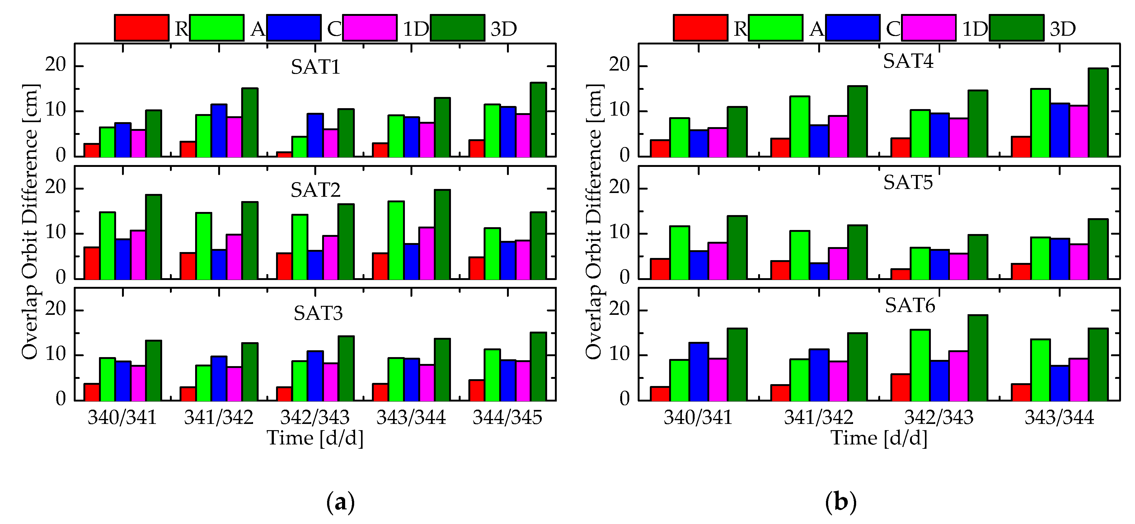
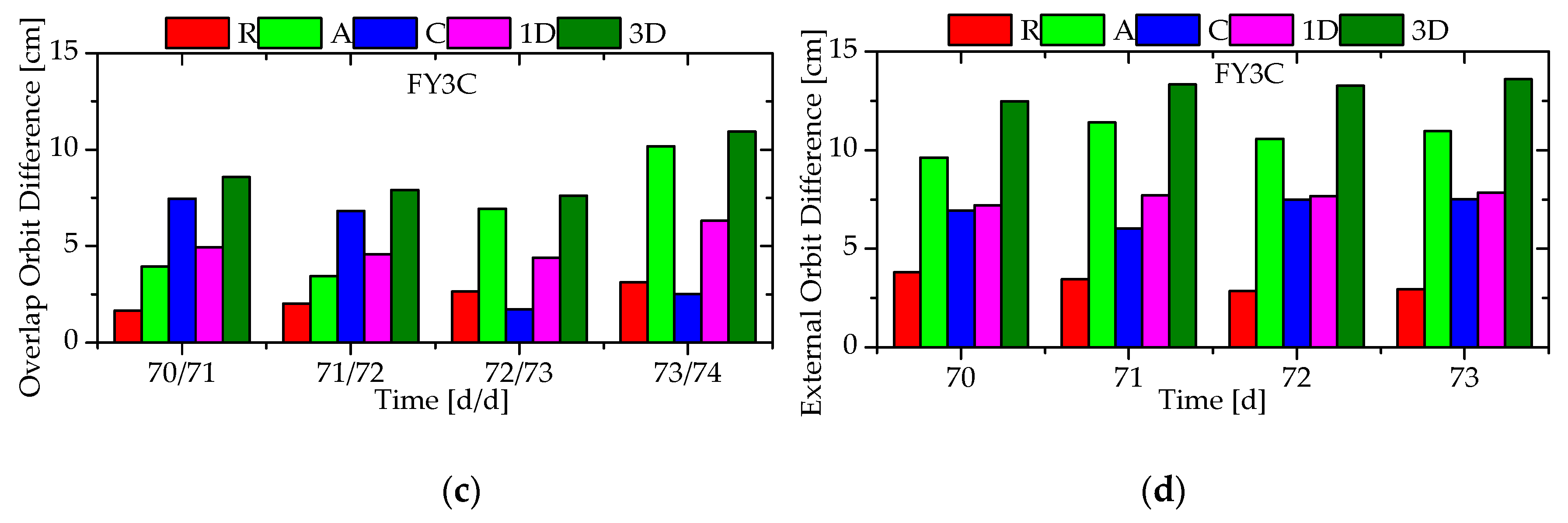
3.2. Reference Orbits

It is necessary to assess the post orbit accuracy firstly before using the post POD orbits of PANDA as reference. For the FY3C satellite with dual-frequency GPS/BDS receiver, the post POD orbits are generated by processing dual-frequency carrier-phase and pseudo-range measurements. Figure 1 shows the root mean square (RMS) statistics of the radial (R), along-track (A), cross (C), 1-dimensional (1D) and 3-dimensional (3D) orbit differences in the middle 5h-overlap arc between two 30 h POD arcs, and the daily RMS statistics of the difference between the post POD orbits and the external precise orbit products released by CMA/NSMC [5]. As can be observed from sub-graph (a), the 1D and 3D overlap differences are about 0.5–2.0 cm and 1.5–3.0 cm, respectively. Sub-graph (b) illustrates the 1D and 3D orbit differences from the external precise orbit products are about 1.0–2.0 cm and 2.5–3.5 cm, respectively, except for a poor performance on day 2015/74 due to less tracked GPS satellites over the arc of 16–24 h. Obviously, the post orbit accuracy of FY3C satellite is at the centimeter level (2–4 cm), so the post POD orbits can be treated as reference to assess the real-time orbit accuracy of SATPODS.
For the YG30/SAT1–SAT6 satellites, it is difficult to obtain high-precision post POD orbits with accuracies at the centimeter level, because the space-borne GPS/BDS receivers only provide single-frequency pseudo-range data. It seems impossible to assess the absolute accuracy of the post POD orbits, due to lack of external precise orbit products. The RMS statistics of the overlap orbit differences of the YG30/SAT1–SAT6 satellites are all shown in sub-graph (a) and (b) of Figure 2. As a comparison, the RMSs of overlap and external orbit differences of the FY3C satellite are also illustrated in sub-graph (c) and (d), where the precise orbits are generated by using only single-frequency pseudo-range measurements. As can be observed from sub-graphs (c) and (d), the RMSs of 1D and 3D overlap orbit differences of the FY3C satellite are about 4–7 cm and 7–11 cm, respectively, and those of 1D and 3D external orbit differences 5–8 cm and 12–14 cm, respectively. Sub-graphs (a) and (b) illustrate the RMSs of overlap orbit differences of SAT1–SAT6 satellites are all of similar magnitude, and the 1D and 3D differences are about 7–11 cm and 10–20 cm, respectively. It may be possible to give an external accuracy indicator for the YG30 series satellites by applying an RMS ratio parameter of FY3C satellite. The FY3C RMS ratio is defined as the ratio of the RMS of the external orbit differences over the RMS of the overlap orbit differences. If the YG30 series satellites are assumed to have the same RMS ratio of the FY3C satellite, then the RMSs of the “external” orbit differences of the YG30 series satellites are inferred from the RMSs of the overlap orbit differences, even if the external orbits of STA1–SAT6 satellites don’t exist.
Table 2 summarizes the overall statistics of the overlap and external orbit difference of the FY3C satellites. The RMS of the 3D overlap orbit differences is 8.9 cm, while that of the corresponding external orbit differences is 13.2 cm. It illustrates that the true orbit external accuracy is worse than the internal overlap accuracy. Moreover, it is reasonable to believe that, the post orbit accuracy of the FY3C satellite is at about 10–15 cm level if only using single-frequency pseudo-range measurements. The ratios of the external over the overlap statistics values are respectively 1.35, 1.59 and 1.33 in the R/A/C directions, and the 1D and 3D ratios are both 1.49. Applying these ratios, the RMSs of the “external” orbit differences of the YG30/SAT1–SAT6 satellites in R/A/C/1D/3D directions are obtained, which are listed in Table 2, too. The inferred “external” orbit accuracies are about 10–15 cm and 15–26 cm in terms of 1D and 3D orbit differences, respectively. It may be concluded that the true post orbit accuracies of the YG30/SAT1–SAT6 satellites are at about 20–25 cm level if only using single-frequency pseudo-range measurements. Compared to the FY3C satellite, the inferior post POD orbits are achieved for the YG30/SAT1–SAT6 satellites. The reason of the poor POD performance is probably that the pseudo-range measurement noises of the single-frequency GPS/BDS receiver onboard the YG30/SAT1–SAT6 satellites are higher than that of the dual-frequency GPS/BDS receiver onboard the FY3C satellite. Figure 3 presents the RMS statistics of single-frequency pseudo-range residuals after POD processing. The pseudo-range residuals of the FY3C satellites are at about 0.3–0.7 m level, while those of the YG30/SAT1–SAT6 satellites are about 0.8–1.8 m.
In summary, the reference orbits of the FY3C satellite are generated by using dual-frequency carrier-phase and pseudo-range measurements, and the orbit accuracy is at 2–4 cm level. The reference orbits of the YG30/SAT1–SAT6 satellites are generated by processing single-frequency pseudo-range measurements and the orbit accuracies are at 20–25 cm level.

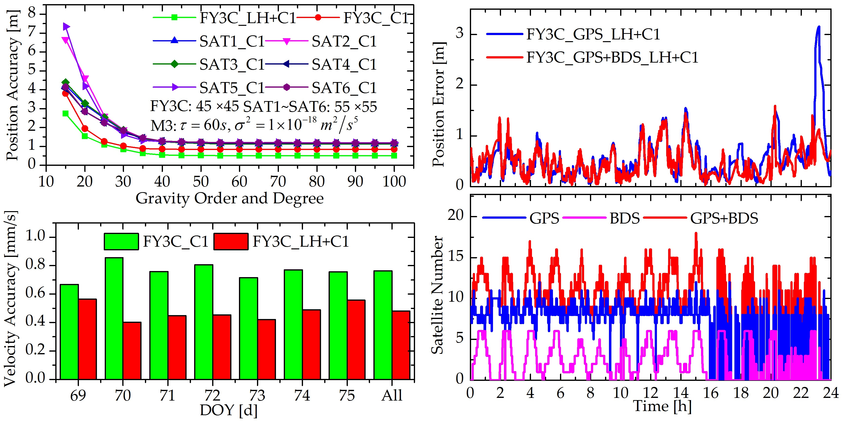
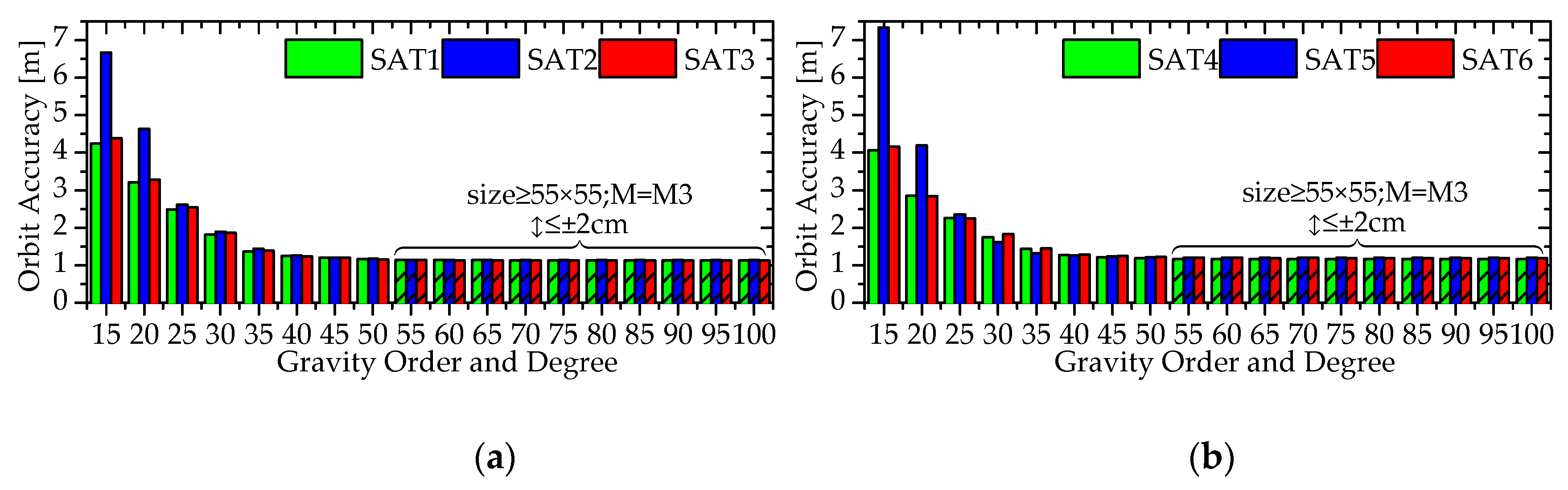
3.3. Force Model Trade-off

Among all perturbations on the LEO satellite orbits, the gravity of the Earth is absolutely a dominant factor for the overall computational load and real-time orbit accuracy. An Earth gravity model of high order/degree is required to obtain high-precision real-time orbit results, but this would lead to unacceptable onboard computing requirements. Therefore, it is necessary to truncate the Earth gravity model that reduces the onboard computational load and prevents notable loss of orbit accuracy at the same time. In addition, the empirical accelerations are estimated with a first-order Gauss-Markov model to compensate the inaccuracy of the force models. The correlated time τ and the power spectral density σ 2 of the process noise in the first-order Gauss-Markov model are essential stochastic parameters to make the force models fit with the measurements. Therefore, several tests with different sizes of gravity models and different stochastic parameters ( τ , σ 2 ) are conducted to assess the impact of force models with different qualities on orbit determination accuracy, and to identify a reasonable force model for the FY3C and YG30/SAT1–SAT6 satellites. The EGM2008 gravity model is used in the tests. The order/degree of the model varies from 5 × 5 to 100 × 100 in an increase of 5 orders and degrees, and thus there are 18 truncated models tested. At the same time, 4 sets of stochastic parameters ( τ , σ 2 ) are employed for each truncated gravity model, namely (1) τ = 1   s ,   σ 2 = 1 × 10 14   m 2 / s 5 ; (2) τ = 30   s ,   σ 2 = 1 × 10 16   m 2 / s 5 ; (3) τ = 60   s ,   σ 2 = 1 × 10 18   m 2 / s 5 ; (4) τ = 900   s ,   σ 2 = 1 × 10 20   m 2 / s 5 , which are abbreviated respectively as “M1”, “M2”, “M3” and “M4”. In these four sets of parameters, the one resulting in the best orbit accuracy is marked as “M” for each truncated gravity model. It should be noted that, both GPS and BDS measurements are used in the tests.
Figure 4 shows the real-time orbit accuracies in terms of the 3D position for the FY3C satellite under the force models of different settings, and sub-graphs (a) and (b) are corresponding to the carrier-phase-based and pseudo-range-based solutions, respectively. In the bottom panel of sub-graph (a), each curve represents a set of stochastic parameters ( τ , σ 2 ) and 18 truncated gravity models, and 4 curves correspond to M1, M2, M3 and M4. As can be seen, if the size of the gravity model is 15 × 15 or 20 × 20, the optimal stochastic parameters resulting in the best real-time orbit accuracy are M2. When the size is more than 35 × 35, the optimal setting is M3. The real-time orbit accuracies under different sizes of gravity models with the corresponding optimal stochastic parameters setting are listed in the top panel. As can be observed clearly, when the size increases from 5 × 5 to 45 × 45, the real-time orbit accuracy is improved from 2.730 m to 0.527 m monotonically. If the size increases from 45 × 45 to 100 × 100, the real-time orbit accuracy varies from 0.527 m to 0.513 m, where the accuracy is only marginally improved by 1.4 cm. Obviously, it is not worthy to achieve this slight accuracy improvement of less than 2.0 cm with the greatly increased onboard computational load caused by the large size of the gravity model. Therefore, 45 × 45 is the minimal order and degree, namely the most time-saving size, to get a reasonable orbit result without sacrificing the real-time orbit accuracy notably (≤ 2 cm). Sub-graph (b) is similar to (a), where 45 × 45 is the optimal size and M3 is the optimal stochastic parameters setting, too. As a whole, the gravity model of 45 × 45 together with the stochastic parameters of M3 are the optimal force model setting for the FY3C satellite, which results in the superior real-time orbit accuracies of 0.527 m and 0.847 m for the carrier-phase-based and pseudo-range-based solutions, respectively.
The real-time orbit accuracies of the YG30/SAT1–SAT6 satellites under different sizes of the gravity model are shown in Figure 5. For each size, only the orbit accuracy corresponding to the optimal stochastic parameters setting M is presented here. Similarly, for the YG30/SAT1–SAT6 satellites, the increase of the size after 55 × 55 only improves the orbit accuracy by less than 2.0 cm, so the most reasonable size of the gravity model is 55 × 55. Moreover, with the size of 55 × 55, the optimal stochastic parameters setting is all M3. With the optimal force models, the real-time 3D orbit accuracies of 1.143 m, 1.140 m, 1.144 m, 1.171 m, 1.1200 m and 1.197 m are achieved for the SAT1–SAT6 satellites, respectively. Compared to the FY3C satellite, a slightly bigger size of the gravity model is required for the YG30 series satellites. The reason for the difference is that the YG30 satellites are at a lower altitude of about 600 km compared to the FY3C at 836 km, which would require higher order/degree of the gravity model to account for the stronger gravity perturbation. In the following experiments, the gravity model is truncated to 45 × 45 and 55 × 55 for the FY3C and YG30 series satellites, respectively, and the stochastic parameters of empirical accelerations are all set as M3: τ = 60   s ,   σ 2 = 1 × 10 18   m 2 / s 5 .

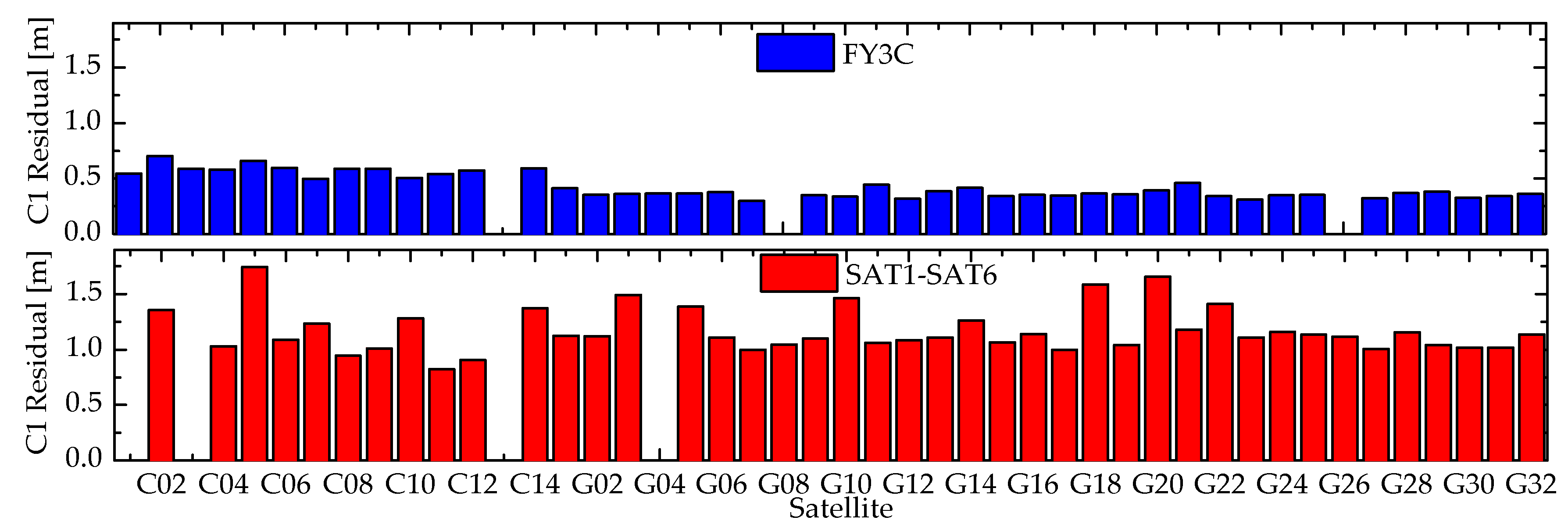
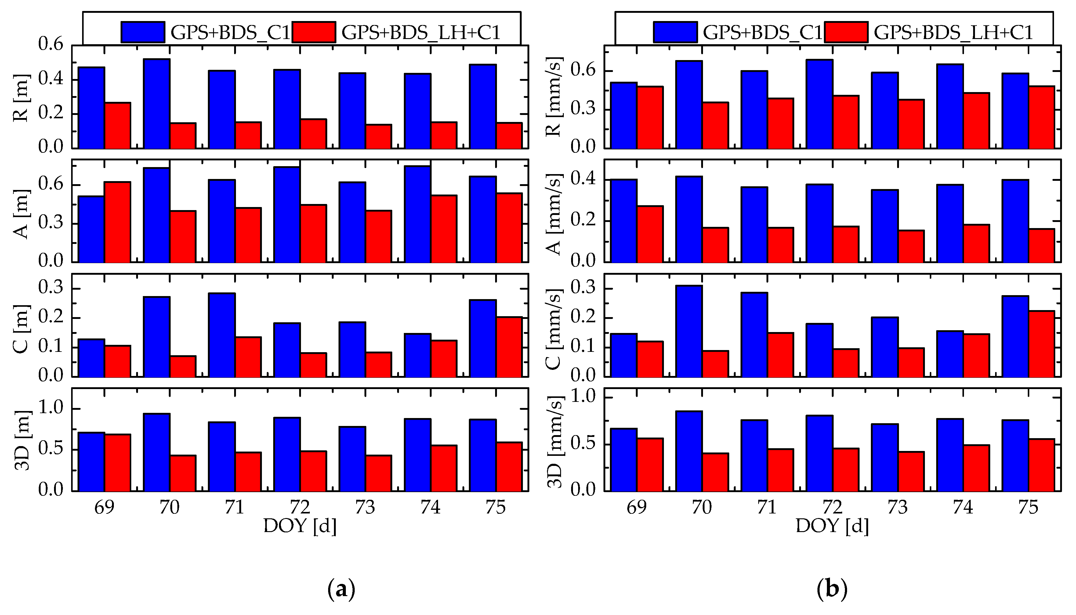
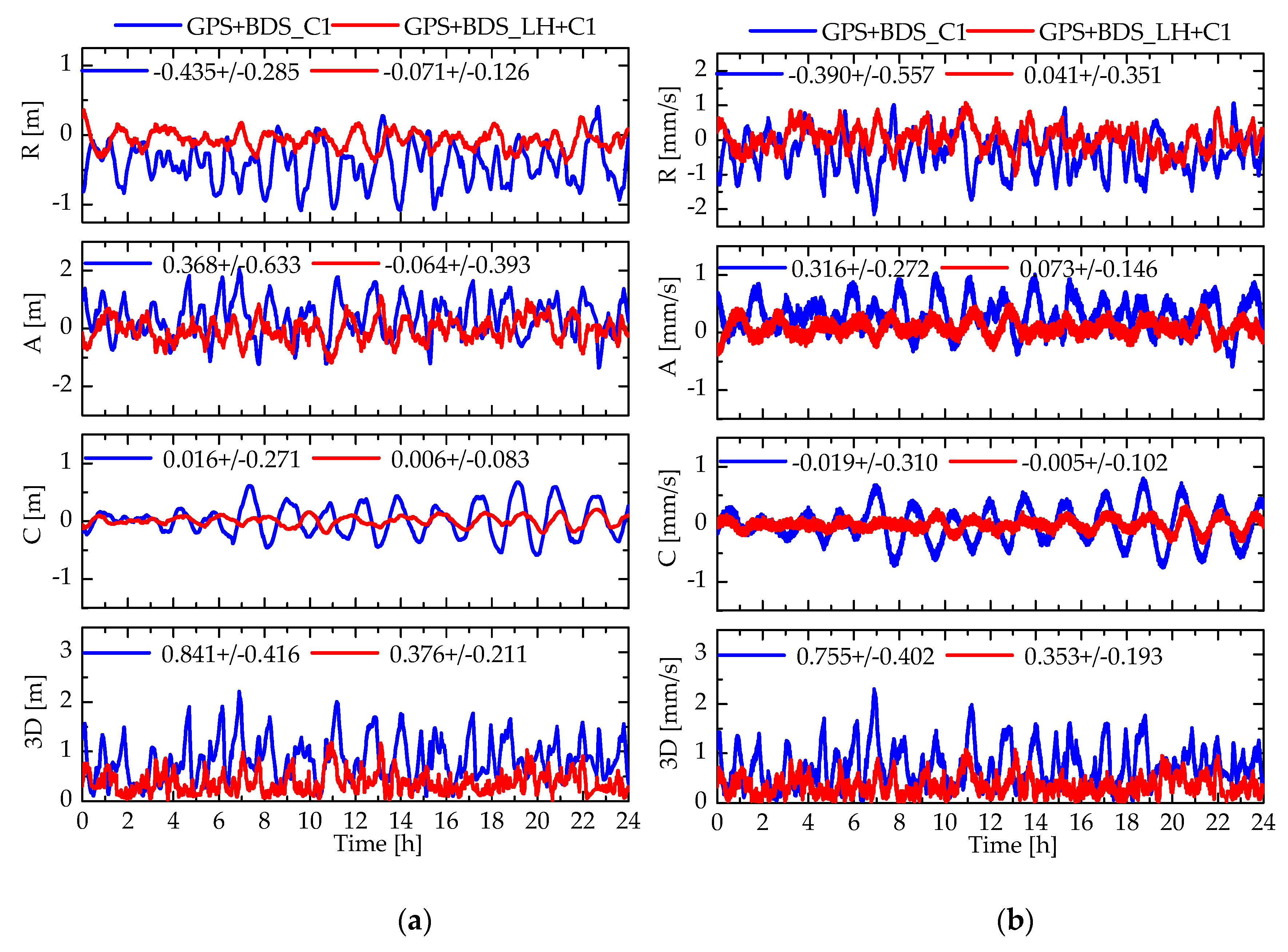
3.4. Effect of Measurements Type

As described above, for the single-frequency GPS/BDS receiver, two solutions with different types of measurements can be obtained: (1) the pseudo-range-based solution, namely only using the single-frequency GPS/BDS pseudo-range measurement (C1), which is abbreviated as “GPS+BDS_C1”; (2) the carrier-phase-based solution, namely using the GRAPHIC combination (LH) and pseudo-range measurement (C1), which is shortened as “GPS+BDS_LH+C1”. The daily position and velocity accuracy statistics of the GPS+BDS_C1 and GPS+BDS_LH+C1 solutions for the FY3C satellite on day 2015/69–75 are shown in Figure 6. The R/A/C/3D position accuracies of the pseudo-range-based solution are at 0.4–0.6 m, 0.5–0.8 m, 0.1–0.3 m and 0.7–1.0 m level, respectively, while those of the carrier-phase-based solution are improved dramatically to 0.1–0.3 m, 0.4–0.6 m, 0.1–0.3 m and 0.4–0.7 m level. Similarly, the R/A/C/3D velocity accuracies of the pseudo-range-based solution are about 0.5–0.7 mm/s, 0.4–0.5 mm/s, 0.1–0.4 mm/s and 0.7–0.9 mm/s, respectively, which are inferior to those of the carrier-phase-based solution, namely 0.4–0.5 mm/s, 0.2–0.3 mm/s, 0.1–0.3 mm/s and 0.4–0.6 mm/s. The results demonstrate that the real-time orbit accuracy of carrier-phase-based solutions is notably better than that of pseudo-range-based solutions.
The R/A/C/3D position and velocity errors of the pseudo-range-based and carrier-phase-based solutions on day 2015/71 are illustrated in Figure 7, and also their arithmetic mean and standard deviation statistics. As can be seen firstly, the variation magnitudes of the R/A/C/3D position and velocity errors of the carrier-phase-based solution are all notably smaller compared to those of the pseudo-range-based solution. Comparing the R/A/C error curves of these two solutions further, it can be observed that the R/A position and velocity errors of the pseudo-range-based solution all contains a notable overall deviation from the zero-axis, which indicates the real-time orbit results are affected by the systematic errors significantly. In the pseudo-range-based solution, the systematic errors include the residual ionospheric delay, broadcast ephemeris errors, group delay variation, phase center variation, and so on. According to the statistics, the arithmetic mean of the R/A position and velocity errors of the pseudo-range-based solution are −0.435 m, 0.368 m, −0.390 mm/s and 0.316 mm/s, respectively, while those of the carrier-phase-based solution are reduced to −0.071 m, −0.064 m, 0.041 mm/s and 0.073 mm/s dramatically, which means there is no obvious systematic error residua in the carrier-phase-based solution. The reason for the notably reduced systematic error in the carrier-phase-based solution is that the used GRAPHIC combination eliminates the first-order ionospheric error and the estimated pseudo-ambiguity could absorb the LOS error caused by the GNSS broadcast ephemeris or other error sources. In conclusion, a notably superior orbit results can be achieved if using the carrier-phase measurements, compared to the solution only using pseudo-range measurements.
For the YG30/SAT1–SAT6 satellites, only the pseudo-range measurement is available. Figure 8 presents the position and velocity accuracies of pseudo-range-based solution. As can be observed, the R/A/C/3D position accuracies of the SAT1–SAT6 satellites are at 0.4–0.8 m, 0.7–1.3 m, 0.2–0.7 m and 0.8–1.6 m, respectively, and the R/A/C/3D velocity accuracies are about 0.8–1.5 mm/s, 0.4–0.7 mm/s, 0.2–0.6 mm/s and 0.9–1.7 mm/s. The orbit accuracies for all satellites are similar, due to identical space-borne GNSS receiver and altitude. The overall real-time orbit accuracies of FY3C and YG30/SAT1–SAT6 satellites in the whole session are presented in Table 3. For the FY3C satellite, the real-time orbit accuracy is 0.527 m for position and 0.479 mm/s for velocity with the carrier-phase-based solution and 0.847 m for position and 0.764 mm/s for velocity with the pseudo-range-based solution, respectively. Compared with the FY3C satellite, the inferior real-time orbit accuracy is achieved for the YG30/SAT1–SAT6 satellites, which is about 1.1–1.2 m for position and 1.2–1.3 mm/s for velocity. The reason of the poor performance is probably that the pseudo-range measurements from the single-frequency GNSS receiver onboard the YG30/SAT1–SAT6 satellites have a ranging noise higher than that from the dual-frequency GNSS receiver onboard the FY3C satellite. Furthermore, the reference orbit accuracies of YG30/SAT1–SAT6 satellites are at 20–25 cm level, which are not sufficiently precise and perhaps also lead to worse real-time orbit accuracy assessment.

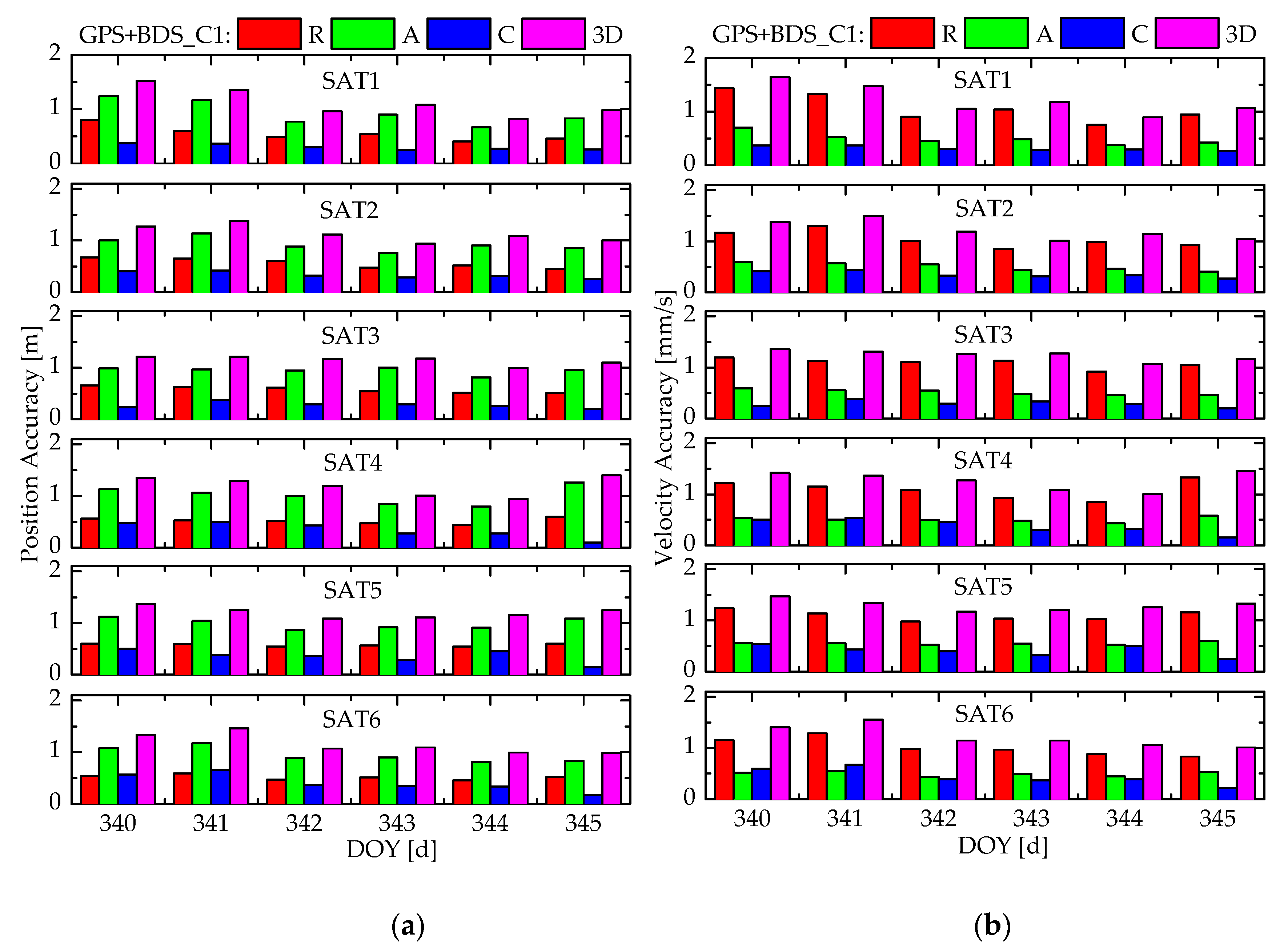
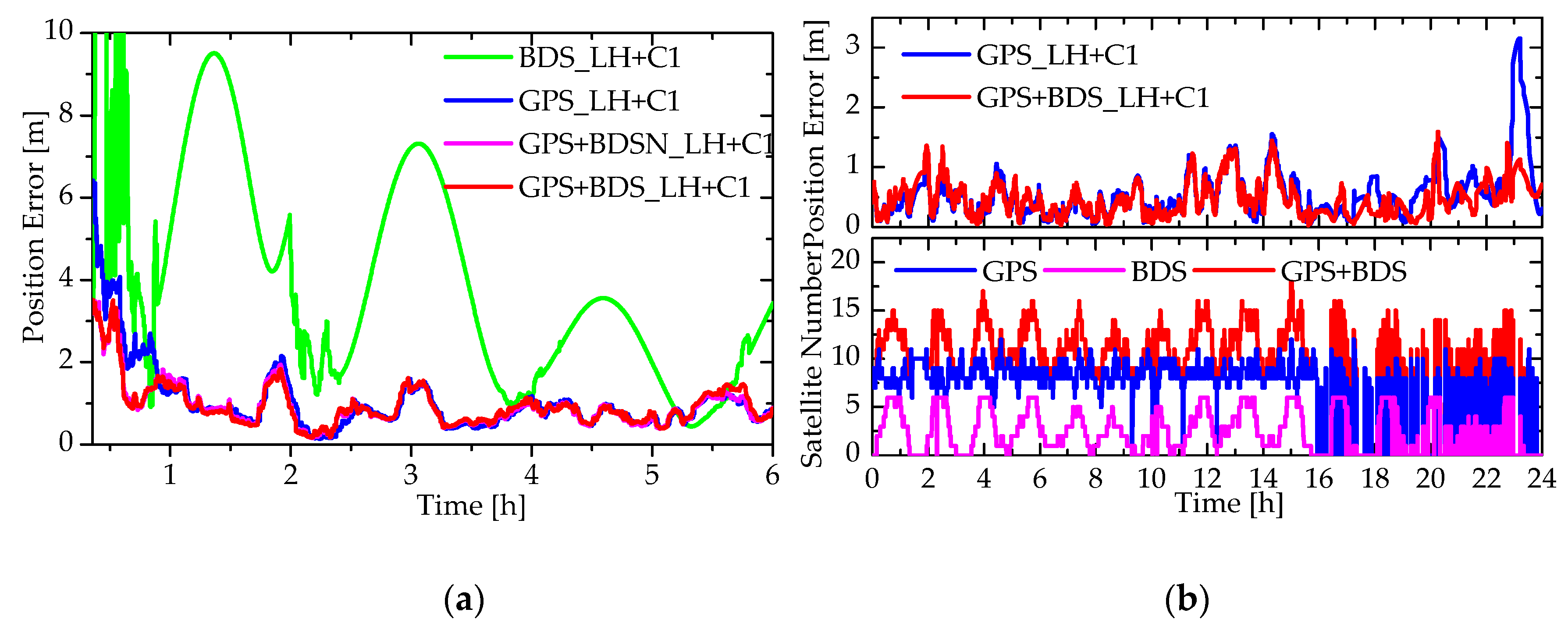
3.5. Impact of GPS/BDS Fusion

The most direct impact of the GPS/BDS fusion is to make more GNSS satellites observed to enhance the observation geometric condition of LEO satellite orbit determination. The number of tracked GNSS satellites by the FY3C and YG30/SAT1–SAT6 satellites for GPS/BDS fusion solutions are shown in Figure 9, where the SAT1 satellite represents all YG30 series satellites due to their similar orbit configurations. There are four types of GPS/BDS combinations to be compared in total: (1) BDS alone; (2) GPS alone; (3) GPS and BDS IGSO/MEO fusion, which is shorted as “GPS + BDSN”, where BDSN means the BDS GEO satellites are not included; (4) GPS and BDS fusion, which is marked as “GPS + BDS”. For the YG30 series satellites, the sub-satellite points distribute at the latitude range of ± 35°, due to their low inclination angles of about 35°. Only the BDS-2 regional navigation system is available for the FY3C and YG30 series satellites, so only in the Asia/Pacific region more than 4 BDS satellites can be tracked, and the numbers of tracked GNSS satellites in other regions are always less than 4. GPS is available for the global navigation service, thus in most places of the world more than 4 GPS satellites can be tracked. Compared to GPS-alone system, the GPS+BDSN and GPS+BDS combinations increase the number of tracked GNSS satellites notably, especially in the Asia/Pacific region where GEO/IGSO satellites of BDS are tracked. According to the statistics, the FY3C and YG30 series satellites can track an average of 8.4 and 10.7 GNSS satellites, while the average numbers of tracked GNSS satellites increase to 11.4 and 12.7, respectively, if the BDS satellites are added. The position dilution of precision (PDOP) can directly describe the observation geometry of LEO satellites. Table 4 summarizes the PDOP statistics of the FY3C and YG30/SAT1–SAT6 satellites under four GPS/BDS combinations. As can be observed clearly, the observation geometry is poor if only BDS is used and improves significantly if GPS is available, while the geometry improves further with the GPS/BDS fusion.
In order to realize the fusion of GPS and BDS data, the bias η between the GPS and BDS system is estimated as an unknown parameter in the onboard RTOD algorithm, which is modeled by a random walk process. Figure 10 shows the estimated bias sequences for the FY3C and YG30/SAT1 satellites. Since BDS is a regional system for the experiment times, there are apparently two scenarios. In the first one, no BDS satellites are trackable, and in the second one, both GPS and BDS satellites are trackable. Comparing the middle and bottom panels, it can be observed that, for the arcs without BDS satellites, the bias varies drastically, because no BDS observations are available to measure the bias. According to the statistics, the standard deviations (STD) of the estimated biases are up to 7.0 ns and 24.1 ns for the FY3C and YG30/SAT1 satellites, respectively. Obviously, the arcs without BDS satellites occur periodically, when the LEO satellites fly over the no-Asia/Pacific regions as shown in Figure 9. However, it should be noted that the inaccurate estimation of η on these arcs has no effect on the real-time orbit accuracy, because no BDS observations are used for the estimation of orbit parameters. On the other hand, considering the arcs with BDS satellites, as shown in the top panel, the variation amplitude of estimated bias reduces greatly where the STDs are only 3.8 ns and 7.9 ns for the FY3C and YG30/SAT1 satellites, respectively. It indicates that the system bias has been calibrated in the form of the estimated parameters with a certain precision on the arcs with GPS/BDS fusion. Of course, inevitably, the real-time estimation of η is affected by the error of GNSS broadcast ephemeris, the residual ionospheric error, the measurement noises and other uncorrectable errors, so the random jittering appears in the sequences of estimated bias. Compared to the FY3C satellite, the bias for YG30/SAT1 shows more notable variation. The reason of the poor performance is probably that the pseudo-range measurements noises of the YG30/SAT1 satellite are higher than those of the FY3C satellite. Furthermore, the YG30/SAT1 satellite at a lower altitude of 600 km is more susceptible to the ionospheric delays than the FY3C satellite at a higher altitude of 836 km, so the residual ionospheric error will be more obvious after the correction by Klobuchar model. After all, the calibration precision of several nanoseconds is enough for the onboard RTOD with the accuracy of sub-meter~meter level.
The real-time orbit accuracies of the FY3C and YG30/SAT1–SAT6 satellites under different types of GPS/BDS combinations are shown in Figure 11, where “All” represents the overall statistics of the whole interval. For the FY3C satellites, if only using BDS measurements, the real-time orbit accuracy is respectively about 1.5–3.0 m for position and 1.5–2.5 mm/s for velocity with the carrier-phase-based solution and about 2.0–9.0 m for position and 2.0–8.0 mm/s for velocity with the pseudo-range-based solution. The poor performance with BDS-alone system is caused by a few tracked BDS satellites and the large orbit and clock errors of the BDS broadcast ephemeris. If using GPS measurements, a real-time orbit accuracy of 0.4–0.7 m for position and 0.4–0.7 mm/s for velocity is achieved with the carrier-phase-based solution, while that of the pseudo-range-based solution is 0.7–1.0 m for position and 0.7–0.9 mm/s for velocity, respectively. Compared to the GPS-alone system, the GPS + BDSN and GPS + BDS combinations only improve the overall orbit accuracy of the carrier-phase-based solution by 3.2 cm, but decrease that of the pseudo-range-based solution by 1.7 cm. No matter improvement or degradation, the slight change of 1.0–3.0 cm level is of little significance or even meaningless from the view of accuracy. It indicates that GPS/BDS fusion could not contribute to accuracy improvement notably. The similar conclusion can be obtained from the real-time orbit accuracies comparison of the YG30/SAT1–SAT6 satellites with different GPS/BDS combinations. As can be seen from sub-graphs (c) and (d), for the YG30/SAT1–SAT6 satellites, the real-time orbit accuracy is about 3.0–10.0 m for position and 3.0–10.0 mm/s for velocity with the BDS-alone system, and that of the GPS-alone solution is about 1.1–1.2 m for position and 1.2–1.3 mm/s for velocity, while the GPS + BDSN and GPS + BDS fusions only improve or reduce the orbit accuracy by 1.0–3.0 cm, which could be negligible, too.
It should be noted that the GPS/BDS combination is of important significance from other aspects. Firstly, the fusion of GPS/BDS data could speed up the convergence of the Kalman filter, as shown in the sub-graph (a) of Figure 12. For the FY3C satellite, if only using BDS measurements, the filter is in the state of prediction at most epochs due to less than 4 tracked BDS satellites for most of the time, so it costs a long time to achieve convergence. If only using GPS measurements, the filter needs about 1.2 h for the position error to converge to less than 1.0 m, while the convergent time decreases to about 0.7 h for the GPS + BDSN and GPS + BDS solutions. More importantly, the main advantage of the GPS/BDS fusion is not reduced convergence time, but the improved reliability of the onboard RTOD. Sub-graph (b) of Figure 12 shows the position errors of the GPS-alone and GPS/BDS solutions and the corresponding number of the tracked GPS and BDS satellites on day 2017/74, where there is an anomalous arc covering 16–24 h. In this abnormal arc, the space-borne GPS/BDS receiver is in an unstable state and cannot track the GPS satellites continuously. As can be observed clearly, if only using GPS measurements, the position error varies drastically to 3.2 m, while the position error is reduced to less than 1.5 m dramatically when the BDS satellites are included. Obviously, the inclusion of BDS satellites could make more GNSS satellites observed to suppress the local orbit error in some anomalous arc where GPS satellites are in a bad tracking. Although the anomalous arcs may not occur often, it can be generally concluded that the GPS/BDS fusion guarantees the orbit accuracy, improves the reliability and availability of onboard RTOD.

4. Conclusions

We have studied the onboard RTOD algorithm only using single-frequency GPS/BDS pseudo-range and carrier-phase measurements. The effects of different force models, different measurements and different GPS/BDS fusions are analyzed in detail through the experiments of processing single-frequency GPS/BDS data from the FY3C and YG30 series satellites. The experiments demonstrate that, with an Earth gravity model of higher order and degree, higher real-time orbit accuracy can be achievable, while the corresponding computation would be more time-consuming, therefore, an appropriate size needs to be determined to save the computational load and avoid the notable loss of orbit accuracy at the same time. This leads to the use of order/degree 45 × 45 for the FY3C satellite and 55 × 55 for the YG30 series satellites. The different stochastic model settings of empirical accelerations will result in vastly different real-time orbit results, so a reasonable stochastic model is essential to get the best real-time orbit accuracy. Under the optimal force model, different measurements also lead to different real-time orbit accuracies. If using the single-frequency carrier-phase and pseudo-range measurements, a real-time orbit accuracy of 0.4–0.7 m for position and 0.4–0.7 mm/s for velocity is achieved for the FY3C satellite, which is notably superior to those of the solution only using pseudo-range measurements, where the real-time orbit accuracy is 0.7–1.0 m for position and 0.7–0.9 mm/s for velocity, respectively. For the YG30 series satellites, only the single-frequency pseudo-range measurements are available, the real-time orbit accuracy is about 0.8–1.6 m for position and 0.9–1.7 mm/s for velocity, respectively. No matter pseudo-range-based or carrier-phase-based solution, the different combination of GPS/BDS has different influence on onboard RTOD. If only using BDS measurements, the orbit accuracy is up to several meters due to only few tracked BDS regional navigation satellites and the large orbit and clock errors in the broadcast ephemeris. Of course, this poor performance will be improved if the BDS global navigation satellites are tracked in the near future. The GPS-alone solution could obtain a superior orbit results, but only slight accuracy improvement or even degradation is obtained when BDS satellites are included, even if the GPS/BDS fusion makes more GNSS satellites observed compared to GPS-alone system. However, the GPS/BDS fusion solution could speed up the convergence of Kalman filter effectively. Furthermore, the main advantage of the GPS/BDS fusion is to make up for the lack of tracked GPS satellites, suppress the local orbit errors and improve the reliability and availability of onboard RTOD, especially in some abnormal arcs.
For small/micro satellite missions with low-cost single-frequency GPS/BDS receivers, the design of the onboard RTOD algorithm depends on the computational capacity of onboard micro-processers and the availability of GPS/BDS data from the receiver. If the onboard micro-processer has enough computational capability and the receiver could provide carrier-phase and pseudo-range measurements, the carrier-phase-based solution with more complex force models can be adopted, and then a real-time orbit accuracy of 0.4–0.7 m level is achievable. However, if only the pseudo-range measurements are available for some missions, such as the YG30 series satellites, the pseudo-range-based solution with simpler force models might be the only alternative, and thus only the inferior orbit accuracy at the 0.8–1.6 m level is obtained. Moreover, from the view of reliability, the GPS/BDS fusion can lead to more reliable real-time orbit results, if both GPS and BDS satellites are tracked. In conclusion, robust and real-time orbit results with accuracies at the sub-meter to meter level are feasible for onboard RTOD with a low-cost single-frequency GPS/BDS receiver, which is of important significance for small/micro satellites. A stable and accurate onboard RTOD algorithm and software has been developed in this paper, which will be an alternative choice for more space missions in the future.

Author Contributions

In this study, X.G. and L.G. designed the algorithm, performed experiments and wrote this paper. F.W. and W.Z. designed the software, performed experiments, analyzed data and edited the manuscript. J.S., M.G. and H.S. supervised its analysis and edited the manuscript.

Funding

This research was funded by the National Natural Science Foundation of China (Nos. 91638203).

Acknowledgments

We are very grateful to the IGS MGEX to provide the GPS/BDS precise orbit and clock products. We would like to thank four reviewers for their valuable comments and suggestions. Special thanks to the Meteorological Administration/National Satellite Meteorological Center (CMA/NSMC) of China for providing the space-borne GPS/BDS data of the FY3C satellite and Wuxi Kalman Navigation Technology Co., Ltd. for providing the GPS/BDS data of the YG30 series satellites.

Conflicts of Interest

The authors declare no conflict of interest.

References

  1. Fang, B.T.; Seifert, E. An evaluation of Global Positioning System data for Landsat-4 orbit determination. In Proceedings of the AIAA 23rd Space Sciences Meeting, Reno, NV, USA, 14–17 January 1985. [Google Scholar]
  2. Montenbruck, O.; Ramos-Bosch, P. Precision real-time navigation of LEO satellites using global positioning system measurements. GPS Solut. 2008, 12, 187–198. [Google Scholar] [CrossRef]
  3. Wang, F.; Gong, X.; Sang, J.; Zhang, X. A novel method for precise onboard real-time orbit determination with a standalone GPS receiver. Sensors 2015, 15, 30403–34018. [Google Scholar] [CrossRef] [PubMed]
  4. Cerri, L.; Berthias, J.P.; Bertiger, W.I.; Haines, B.J.; Lemoine, F.G.; Mercier, F.; Ries, J.C.; Willis, P.; Zelensky, N.P.; Ziebart, M. Precision orbit determination standards for the Jason series of altimeter missions. Mar. Geod. 2010, 33, 379–418. [Google Scholar] [CrossRef]
  5. Li, M.; Li, W.; Shi, C.; Jiang, K.; Guo, X.; Dai, X.; Meng, X.; Yang, Z.; Yang, G.; Liao, M. Precise orbit determination of the Fengyun-3C satellite using onboard GPS and BDS observations. J. Geod. 2017, 91, 1313–1327. [Google Scholar] [CrossRef] [Green Version]
  6. Sweeting, M.N. Modern small satellites-changing the economics of space. Proc. IEEE 2018, 106, 343–361. [Google Scholar] [CrossRef]
  7. Collins, J.T.; Conger, R.E. MANS: Autonomous navigation and orbit control for communications satellites. In Proceedings of the 15th AIAA International Communications Satellites Systems Conference, San Diego, CA, USA, 28 February–3 March 1994. [Google Scholar]
  8. Guinn, J.R.; Williams, B.G.; Wolff, P.J.; Fennessey, R.; Wiest, T. TAOS orbit determination results using Global Positioning Satellites. Adv. Astronaut. Sci. 1995, 89, 95–146. [Google Scholar]
  9. Wertz, J.R. Autonomous navigation and autonomous orbit control in planetary orbits as a means of reducing operations cost. In Proceedings of the 5th International Symposium on Reducing the Cost of Spacecraft Ground Systems and Operations, Pasadena, CA, USA, 8–11 July 2003. [Google Scholar]
  10. Plam, Y.; Allen, R.V.; Wertz, J.; Bauer, T. Autonomous orbit control experience on TacSat-2 using Microcosm’s Orbit Control Kit (OCK). In Proceedings of the 31st Annual AAS Guidance and Control Conference, Breckenridge, CO, USA, 1–6 February 2008. [Google Scholar]
  11. Hart, R.C.; Hartman, K.R.; Long, A.C.; Lee, T.; Oza, D.H. Global Positioning System (GPS) Enhanced Orbit Determination Experiment (GEODE) on the small satellite technology initiative (SSTI) lewis spacecraft. In Proceedings of the ION-GPS-1996, Kansas City, MO, USA, 17–20 September 1996. [Google Scholar]
  12. Hart, R.C.; Long, A.C.; Lee, T. Autonomous navigation of the SSTI/Lewis spacecraft using the Global Positioning System (GPS). In Proceedings of the Flight Mechanics Symposium, GSFC, Greenbelt, MD, USA, 19–21 May 1997. [Google Scholar]
  13. Gill, E.; Montenbruck, O.; Brieß, K. GPS-based autonomous navigation for the BIRD satellite. In Proceedings of the 15th International Symposium on Spaceflight Dynamics, Biarritz, France, 26–30 June 2000. [Google Scholar]
  14. Gill, E.; Montenbruck, O.; Brieß, K. Flight experience of the BIRD onboard navigation system. In Proceedings of the 16th International Symposium on Space Flight Dynamics, Pasadena, CA, USA, 3–7 December 2001. [Google Scholar]
  15. Gill, E.; Montenbruck, O.; Kayal, H. The BIRD satellite mission as a milestone toward GPS-based autonomous navigation. Navigation 2001, 48, 69–75. [Google Scholar] [CrossRef]
  16. Montenbruck, O.; Gill, E.; Markgraf, M. Phoenix-XNS—A miniature real-time navigation system for LEO satellites. In Proceedings of the NAVITEC’2006, Noordwijk, The Netherlands, 11–13 December 2006. [Google Scholar]
  17. Gill, E.; Montenbruck, O.; Arichandran, K.; Tan, S.H.; Bretschneider, T. High-precision onboard orbit determination for small satellites-the GPS-based XNS on X-SAT. In Proceedings of the 6th Symposium on Small Satellites Systems and Services, La Rochelle, France, 20–24 September 2004. [Google Scholar]
  18. Montenbruck, O.; Nortier, B.; Mostert, S. A miniature GPS receiver for precise orbit determination of the Sunsat 2004 micro-satellite. In Proceedings of the 2004 National Technical Meeting of The Institute of Navigation (ION NTM 2004), San Diego, CA, USA, 26–28 January 2004. [Google Scholar]
  19. Montenbruck, O.; Markgraf, M.; Naudet, J.; Santandrea, S.; Gantois, K.; Vuilleumier, P. Autonomous and precise navigation of the PROBA-2 spacecraft. In Proceedings of the AIAA/AAS Astrodynamics Specialist Conference and Exhibit, Honolulu, HI, USA, 18–21 August 2008. [Google Scholar]
  20. Montenbruck, O.; Swatschina, P.; Markgraf, M.; Santandrea, S.; Naudet, J.; Tilmans, E. Precision spacecraft navigation using a low-cost GPS receiver. GPS Solut. 2012, 16, 519–529. [Google Scholar] [CrossRef]
  21. Zhang, Q.; Guo, X.; Qu, L.; Zhao, Q. Precise orbit determination of FY-3C with calibration of orbit biases in BeiDou GEO satellites. Remote Sens. 2018, 10, 382. [Google Scholar] [CrossRef]
  22. Shi, C.; Zhao, Q.; Geng, J.; Lou, Y.; Ge, M.; Liu, J. Recent development of PANDA software in GNSS data processing. In Proceedings of the International Conference on Earth Observation Data Processing and Analysis (ICEODPA), Wuhan, China, 28–30 December 2008. [Google Scholar]
  23. Wang, F. Theory and Software Development on Autonomous Orbit Determination Using Space-Borne GPS Measurements. Ph.D. Thesis, Wuhan University, Wuhan, China, 2006. [Google Scholar]
  24. Gong, X. Key Technologies and Software toward Decimeter-Level Autonomous Orbit Determination with Space-Borne GPS Carrier-Phase Measurements. Master’s Thesis, Wuhan University, Wuhan, China, 2015. [Google Scholar]
  25. Odijk, D.; Nadarajah, N.; Zaminpardaz, S.; Teunissen, P.J.G. GPS, Galileo, QZSS and IRNSS differential ISBs: Estimation and application. GPS Solut. 2017, 21, 439–450. [Google Scholar] [CrossRef]
  26. Nicolini, L.; Caporali, A. Investigation on Reference Frames and Time Systems in Multi-GNSS. Remote Sens. 2018, 10, 80. [Google Scholar] [CrossRef]
  27. Torre, A.D.; Caporali, A. An analysis of intersystem biases for multi-GNSS positioning. GPS Solut. 2015, 19, 297–307. [Google Scholar] [CrossRef]
  28. Montenbruck, O.; Gill, E. Ionospheric correction for GPS tracking of LEO satellites. J. Navig. 2002, 55, 293–304. [Google Scholar] [CrossRef]
Figure 1. The post orbit accuracy assessment of the FY3C satellite using dual-frequency carrier-phase and pseudo-range measurements in 2015/69–75: (a) The RMS statistics of the radial (R), along-track (A), cross (C), 1-dimensional (1D) and 3-dimensional (3D) orbit difference in the 5h-overlap arcs; (b) The daily RMS statistics of the R/A/C/1D/3D orbit difference from external precise orbit products.
Remotesensing 11 01391 g001
Figure 2. The post orbit accuracy assessment of the YG30/SAT1–SAT6 and FY3C satellites using single-frequency pseudo-range measurements (C1): (a) The RMS statistics of the radial (R), along-track (A), cross (C), 1-dimensional (1D) and 3-dimensional (3D) overlap orbit difference of the SAT1–SAT3 satellites; (b) The RMS statistics of the R/A/C/1D/3D overlap orbit difference of the SAT4–SAT6 satellites; (c) The RMS statistics of the R/A/C/1D/3D overlap orbit difference of the FY3C satellite; (d) The RMS statistics of the R/A/C/1D/3D orbit differences of the FY3C satellite from external precise orbit products.
Remotesensing 11 01391 g002aRemotesensing 11 01391 g002b
Figure 3. The RMS statistics of single-frequency pseudo-range residuals for the FY3C and YG30/SAT1–SAT6 satellites.
Remotesensing 11 01391 g003
Figure 4. Comparison of real-time orbit accuracies of the FY3C satellite under different order/degree of truncated gravity models (15 × 15~100 × 100) and different stochastic parameters setting (M1: τ = 1   s ,   σ 2 = 1 × 10 14   m 2 / s 5 ; M2: τ = 30   s ,   σ 2 = 1 × 10 16   m 2 / s 5 ; M3: τ = 60   s ,   σ 2 = 1 × 10 18   m 2 / s 5 ; M4: τ = 900   s ,   σ 2 = 1 × 10 20   m 2 / s 5 ): (a) The position accuracy of the carrier-phase-based solution; (b) The position accuracy of the pseudo-range-based solution.
Remotesensing 11 01391 g004
Figure 5. Comparison of real-time orbit accuracies of the YG30/SAT1–SAT6 satellites under different force models: (a) The position accuracy of the SAT1–SAT3 satellites; (b) The position accuracy of the SAT4–SAT6 satellites.
Remotesensing 11 01391 g005
Figure 6. Comparison of daily real-time orbit accuracies of the pseudo-range-based and carrier-phase-based solutions for the FY3C satellite: (a) The radial (R), along-track (A), cross (C), 1-dimensional (1D) and 3-dimensional (3D) position accuracy; (b) The R/A/C/3D velocity accuracy.
Remotesensing 11 01391 g006
Figure 7. Comparison of real-time orbit errors of the pseudo-range-based and carrier-phase-based solutions for the FY3C satellite on day 2015/71: (a) The radial (R), along-track (A), cross (C), 1-dimensional (1D) and 3-dimensional (3D) position errors; (b) The R/A/C/3D velocity errors.
Remotesensing 11 01391 g007
Figure 8. Daily real-time orbit accuracy of the YG30/SAT1–SAT6 satellites for the pseudo-range-based solution: (a) The radial (R), along-track (A), cross (C) and 3-dimensional (3D) position accuracy; (b) The R/A/C/3D velocity accuracy.
Remotesensing 11 01391 g008
Figure 9. The number of tracked GNSS satellites for different types of GPS/BDS combinations: (a) for the FY3C satellite; (b) for the YG30/SAT1 satellite.
Remotesensing 11 01391 g009
Figure 10. Estimation of the system bias between GPS and BDS: (a) the estimated bias sequences and the corresponding number of tracked BDS satellites for the FY3C satellite with the pseudo-range-based solution on day 2015/70; (b) the estimated bias sequences and the number of BDS for the YG30/SAT1 satellite with the pseudo-range-based solution on day 2017/341.
Remotesensing 11 01391 g010
Figure 11. Comparison of real-time orbit accuracies of the FY3C and YG30/SAT1–SAT6 satellites for four types of GPS/BDS combinations: (a) The position and velocity accuracy of the FY3C satellite for the carrier-phase-based solution; (b) The position and velocity accuracy of the FY3C satellite for the pseudo-range-based solution; (c) The position accuracy of the YG30/SAT1–SAT6 satellites for the pseudo-range-based solution; (d) The velocity accuracy of the YG30/SAT1–SAT6 satellites for the pseudo-range-based solution.
Remotesensing 11 01391 g011aRemotesensing 11 01391 g011b
Figure 12. Impact of GPS/BDS fusion: (a) Position errors of the FY3C satellite at the convergent stage with the carrier-phase-based solutions for different GPS/BDS combinations on day 2015/69; (b) Position errors of the FY3C satellite with the carrier-phase-based solutions and the number of tracked GNSS satellites on day 2015/74.
Remotesensing 11 01391 g012
Table 1. Comparison of onboard real-time orbit determination (RTOD) and post POD strategies.
ModelOnboard RTOD (SATPODS)Post POD (PANDA)
Measurement model
GNSS dataSingle-frequency GPS/BeiDou Navigation System (BDS) phase and pseudo-range measurements (LH + C1) for the FY3C satellite; and single-frequency pseudo-range data (C1) for the YG30/SAT1–SAT6 satellites (interval 30 s)Dual-frequency GPS/BDS phase and pseudo-range measurements for the FY3C satellite; and single-frequency pseudo-range data (C1) for the YG30/SAT1–SAT6 satellites (interval 10 s)
GNSS orbit and clockBroadcast ephemerisIGS MGEX final precise orbit and clock products
Receiver clockA receiver clock offset and a bias between GPS and BDS systemEpoch-wise receiver clock offset and a bias between GPS and BDS system
AmbiguityPseudo-Ambiguity with a random walk processReal constant value for each ambiguity pass
Dynamical model
Earth gravity fieldTruncated EGM 2008 with low order and degree, neglect the time-varying partEIGEN-6S, adopt 120 × 120, include the time-varying part
N-body gravitationMoon and Sun only, low precision analytic method (position)Moon, Sun and other planets, JPL DE405 (position)
Solid earth tideSimplified model, k 20 solid onlyIERS Conventions 2010
Earth pole tideNeglectedIERS Conventions 2010
Ocean tideNeglectedFES2004
Ocean pole tideNeglectedIERS Conventions 2010
Relativistic effectsNeglectedIERS Conventions 2010
Atmosphere dragModified Harris-Priester model (density), fixed effective area, drag coefficient with a random walk processDTM94 model (density), macro model, drag coefficients every 360 min
Solar radiationCannonball model, fixed effective area, radiation pressure coefficient with a random walk process Macro model, radiation pressure coefficients every 360 min
Earth radiationNeglectedMacro model, radiation pressure coefficients every 360 min
Empirical accelerationthree empirical accelerations in radial, along-track and cross with a first-order Gauss-Markov modelOne-cycle-per-orbit-revolution (1CPR) empirical accelerations in radial, along-track and cross
Reference frame
Coordinate systemWGS84/CGCS2000ITRF 2008/ITRF 2014
Precession/nutationIAU1976/IAU 1980 simplified modelIAU 2006/IAU 2000R06 model
Earth rotation parameterRapid predicted EOP in IERS Bulletin AIERS final EOP products
Estimation
EstimatorEKF filterLeast square
ModeSequential processing in real-timeBatch processing
Table 2. The overall statistics of overlap and external orbit difference and the inferred orbit accuracy of the FY3C and YG30/SAT1–SAT6 satellites.
SATOverlap Orbit Difference (cm)External Orbit Difference (cm)3D Orbit Accuracy (cm)
RAC1D3DRAC1D3D
FY3C2.46.75.35.18.93.310.77.07.613.210–15
Ratio1.351.591.331.491.49
SAT12.98.59.77.713.3~3.9~13.6~12.9~11.4~19.7~20–25
SAT25.814.57.610.017.4~7.8~23.2~10.0~14.9~25.9
SAT33.69.49.68.013.9~4.9~14.9~12.7~11.9~20.6
SAT44.012.08.88.915.5~5.4~19.2~11.7~13.3~23.0
SAT53.69.86.57.112.3~4.8~15.6~8.7~10.6~18.3
SAT64.112.210.49.616.6~5.6~19.5~13.8~14.2~24.6
Table 3. The overall statistics of real-time orbit accuracy.
Accuracy (RMS)Position/mVelocity/mm/s
RAC3DRAC3D
FY3C (LH + C1)0.1710.4830.1220.5270.4190.1860.1390.479
FY3C (C1)0.4670.6720.2170.8470.6180.3850.2310.764
SAT1 (C1)0.5610.9470.3071.1431.0880.5020.3191.240
SAT2 (C1)0.5670.9290.3401.1401.0520.5120.3591.224
SAT3 (C1)0.5810.9460.2771.1441.0890.5200.2961.242
SAT4 (C1)0.5040.9810.3961.1711.0610.4910.4271.245
SAT5 (C1)0.5720.9770.3991.2001.0880.5420.4381.292
SAT6 (C1)0.5140.9770.4631.1971.0610.4900.4921.268
Table 4. Comparison of position dilution of precisions (PDOPs) for different GPS/BDS combinations.
PDOPBDSGPSGPS + BDSNGPS + BDS
FY3C5.4992.4712.2472.123
SAT15.1481.2611.2441.221
SAT24.9951.2811.2521.236
SAT35.8541.2681.2471.222
SAT45.2581.3131.2931.269
SAT55.6301.3201.2951.275
SAT65.7261.2951.2661.244

