Star-Based Calibration of the Installation Between the Camera and Star Sensor of the Luojia 1-01 Satellite


1
State Key Laboratory of Information Engineering in Surveying, Mapping and Remote Sensing, Wuhan University, Wuhan 430079, China
2
School of Remote Sensing and Information Engineering, Wuhan University, Wuhan 430079, China
*
Author to whom correspondence should be addressed.
Remote Sens. 2019, 11(18), 2081; https://0-doi-org.brum.beds.ac.uk/10.3390/rs11182081
Submission received: 30 June 2019
/
Revised: 17 August 2019
/
Accepted: 3 September 2019
/
Published: 5 September 2019
Abstract
:Ground control points (GCPs) are generally used to calibrate the installation between the camera and star sensor of a satellite in orbit and improve the geometric positioning accuracy of the satellite. However, the use of GCPs for high-frequency calibration is difficult, and it is particularly difficult to acquire accurate GCPs for the image of a nightlight satellite. In this study, we developed a camera-star sensor installation calibration method that eliminates the need for GCPs. In the proposed method, the camera and star sensor lenses are simultaneously pointed at the star, and the camera-star sensor installation is accurately calibrated by processing the star map obtained by the camera and star sensors. Reference data such as road network and Moon position data were used to verify the proposed method and evaluate its positioning accuracy. The results of the application of the method to the positioning of the Luojia 1-01 satellite indicated an accuracy within 800 m, which is comparable with that of the traditional method.
1. Introduction
The stress release that occurs during the launch of a satellite and the change in the physical environment when the satellite enters orbit alter the installation between the satellite’s camera and star sensor, resulting in reduced geometric positioning accuracy of images obtained by the satellite. Generally, the orbit determination accuracy may be better than the level of sub-meters, indicating that the main determinant of the positioning accuracy is the attitude accuracy [1,2,3]. Therefore, after sending a satellite into orbit, it is usually necessary to calibrate the installation between the camera and the star sensor. Multiple studies have been performed on in-orbit geometric calibration using ground control points (GCPs). This GCP-based calibration method acquires the precise determination of the parameters of the camera-star sensor installation, thereby improve the image positioning accuracy.
Through a GCP-based method, the Advanced Land Observing Satellite (ALOS) launched from Japan in 2006 achieved an image absolute positioning accuracy of 8 m (3.2 pixels, 2.5 m resolution) [4,5,6]. Similarly, the Pleiades 1A satellite launched from France in 2011 achieved an absolute positioning accuracy of 5.6 m (8 pixels, 0.7 m resolution) [7]. In 2012, the Ziyuan 3-01 satellite was launched from China and achieved an image absolute positioning accuracy of 10 m (4.8 pixels, 2.1-m resolution) by GCP-based method [8,9,10]. The SPOT 6/7 satellite launched from France in 2012/2014 similarly achieved an image absolute positioning accuracy of 7.8 m (3.9 pixels, 2 m resolution) [11]. The Worldview-3/4 satellite launched in 2014/2016 achieved an image absolute positioning accuracy of 2.7 m (8.7 pixels, 0.31-m resolution) [12,13,14]. To eliminate the need for GCPs, Kubik et al., adopted the extremely agile maneuvers of the Pleiades satellite and developed an auto-calibration imaging mode that enables calibration of the camera-star sensor angle error without the use of GCPs [15,16,17,18]. Jiang similarly developed an autonomous calibration method based on agile-maneuver imaging and verified it by simulation [19,20].
However, single calibration cannot guarantee the long-term accuracy of satellite positioning without the use of GCPs. The seasonal illumination changes and temperature alternation between warm and cold that occur during an orbital cycle cause the attitude angle of the camera-star sensor to continuously change over a long period, eventually invalidating the attitude angle or installation obtained by a single calibration, resulting in reduced positioning accuracy. Degradation of the attitude determination accuracy of the ALOS is due to the relative installation changes that occur between its star sensors, which have periodic terms for an orbital cycle and exhibit very long-term drift. Hence, calibration activities are ongoing on GCP-based methods for improving positioning accuracy [21,22]. It has also been found that the positioning accuracy of the Ziyuan 3 satellite deteriorates with increasing time interval between the acquisitions of the calibration and verification images [23,24,25].
To address the problem of the installation change that occurs over an extended period, it is necessary to calibrate the camera-star sensor angle at short time intervals. However, the process of the acquisition of high-precision GCPs is expensive and difficult, and more so for global control points. Moreover, the occurrence of suitable imaging weather conditions without cloud and rain is limited. This makes the use of the existing GCP-based method for repeated calibration at short time intervals challenging. Further, in the case of night imaging satellites, the lack of control data makes it more difficult to achieve calibration through traditional methods. In addition, the auto-calibration method, which similar to that used by the Pleiades satellite, does not require control data, but strong agility of the satellite for the acquisition of a couple of images from the same orbit with 180° direction. The method is therefore poor applicability for the present purpose.
In the present study, we developed a non-GCP method for the calibration of the camera-star sensor of the Luojia 1-01 nightlight satellite. In the proposed method, a camera and star sensor are simultaneously used to obtain images of stars, and the star map so acquired is processed and used to accurately calibrate the installation of the camera-star sensor.
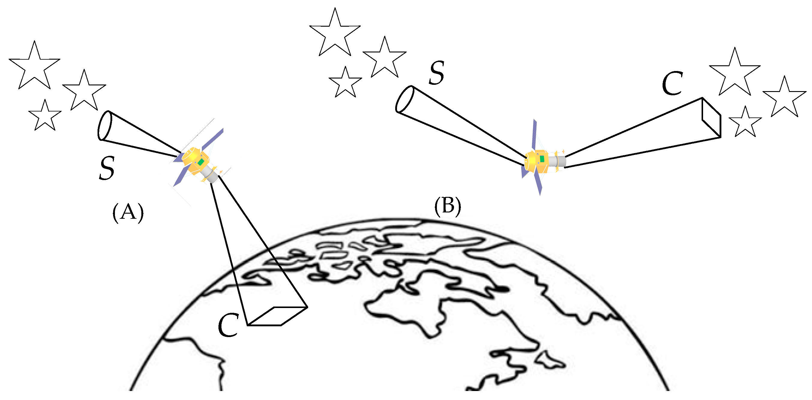
Figure 1A illustrates the conventional imaging model of the Luojia 1-01 satellite. The camera C is the optical axis pointing to a ground target, while the star sensor S is the optical axis pointing to stars. In an inertial system, the attitude of the star sensor is obtained from the ascension and declination of the stars acquired by the star sensor, while the attitude of the camera is obtained by pointing it to a known target (GCP). This enables the determination of the installation angle between the camera and the star sensor. The process corresponds to that of conventional geometric calibration, referred to here as the GCP-based method. The method proposed in this paper is illustrated in Figure 1B. As the satellite maneuvers with some combination of roll, pitch and yaw at a safe speed, it maintains its inertial motion when it assumes a stable positioning direction. The attitudes of the camera C and star sensor S in the inertial system are obtained when they simultaneously photograph stars. The angular relationship between the star sensor and the camera is then deduced and calibration is performed, referred to here as the Star-based method. Because there are no clouds in outer space, the satellite does not have to maneuver in a specific direction, but only needs to keep its camera and star sensor pointed at the star. Most satellites are able to satisfy this requirement.
The Luojia 1-01 satellite was successfully launched on 2 June 2018. The satellite was an experimental nightlight remote sensing satellite developed at the Wuhan University, China, with a resolution of 129 m at a sub-satellite point [26,27]. Star data collected by the camera of the Luojia 1-01 satellite were used in the present study. The details of the satellite and its camera are presented in Table 1. Regarding the imaging mode in the table, the nightlight and daytime modes respectively indicate that the camera is pointing to the earth at night and during the day while imaging; the Moon mode indicates that the camera is pointing to the Moon while imaging; and the star mode indicates that the camera is photographing stars.
2. Materials and Methods
2.1. Star-Based Calibration Principle and Verification Methods
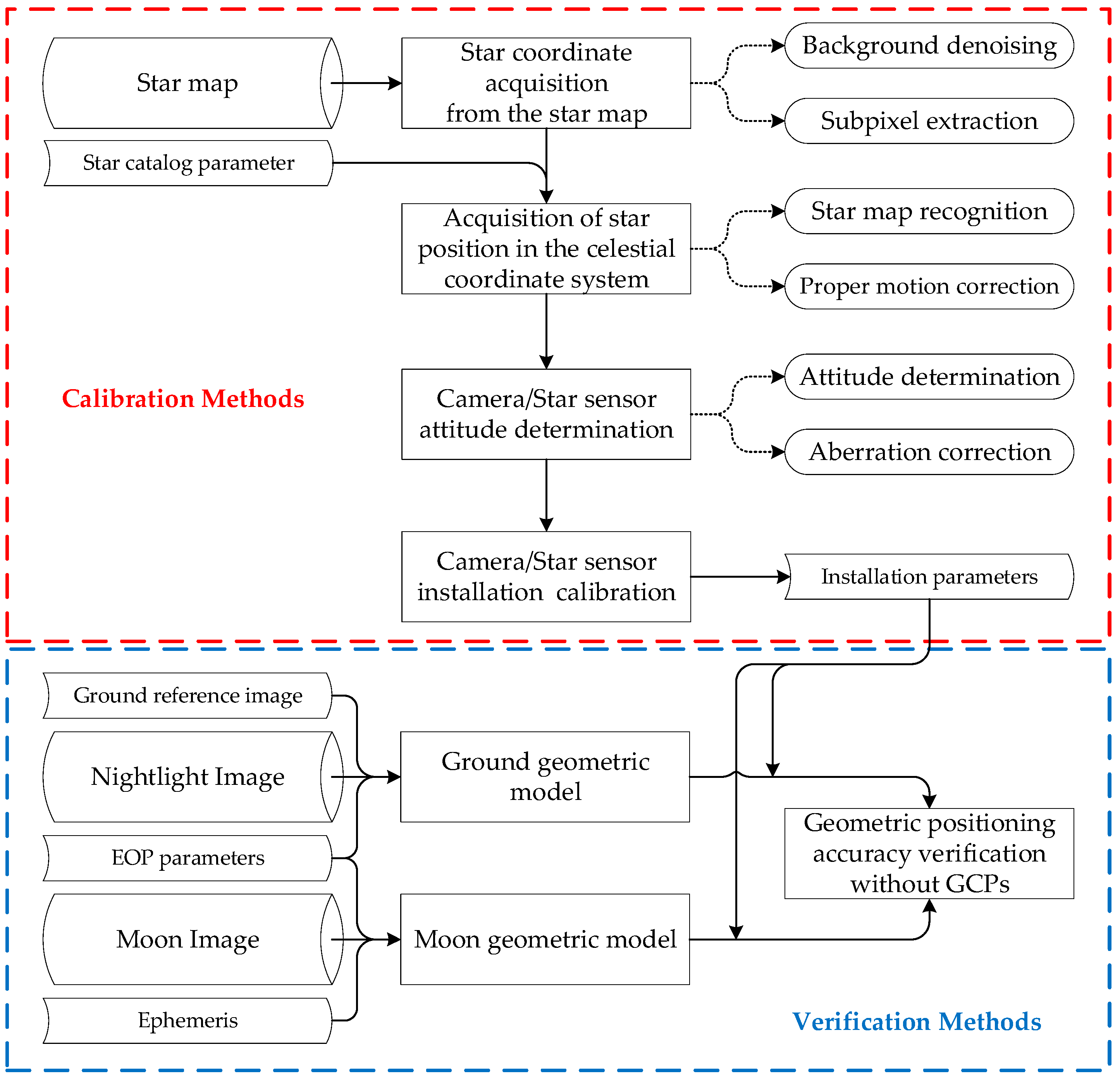
After photographing stars with the camera and star sensor, the star map is processed to determine the attitude of the camera and star sensor in the inertial system. This specifically includes the coordinate extraction of star points from the star map, acquisition of star position in the celestial coordinate system, determination of the attitude in the inertial system by the star sensor and camera, and installation calibration between the star sensor and camera. All these processes include one or two smaller processes, as presented in the calibration methods part of Figure 2. The updated installation parameters of Luojia 1-01 are subsequently acquired. In the present experiment, the geometric positioning accuracies of other images were used to verify the effectiveness of the parameters. Two verification method were considered. In the first method, which is the traditional verification method, check points (CPs) were acquired through the homonymy points between the ground reference images and nightlight images. A ground geometric model and installation parameters were then used to calculate the coordinates of different points. The offset of the calculated coordinates relative to the coordinates of the CPs is a measure of the positioning accuracy. The employed model utilized CPs and did not require the use of GCPs, and the process can thus be referred to as “Geometric positioning accuracy verification without GCPs.” In the second considered verification method, the Moon center was used to replace the CPs. This was a novel approach. The integrated flow chart in Figure 2 details the calibration and verification methods utilized in this study. The images obtained by Luojia 1-01 and other external data used in the study are introduced in the next subsection. Further details are presented farther in the paper.
2.2. Introduction to the Experimental Data
2.2.1. Luojia 1-01 Images
Eleven images obtained by Luojia 1-01 were used in this study. The star mode image was used for calibration and acquisition of the installation parameters from the other images. The nightlight mode and Moon mode images were used for verification. The effective duration of the star data obtained in this experiment was consisted of 146 scenes of star maps which imaging approximately 15 s (0.1 s exposition time per scene). The data details are presented in Table 2.
2.2.2. External Data
The employed star catalog data was obtained by the Smithsonian Astrophysical Observatory (SAO) in the J2000 epoch. Based on the limiting magnitude of the SAO catalog, which contains about 300,000 stars, stars with a magnitude of less than five were selected. Based on the proper motion correction algorithm, which depends on the position of the stars, approximately 1500 navigation stars were selected from the experimental catalog data [28].
The Earth orientation parameters (EOP) of the Earth reference system relative to the celestial reference system were obtained from the International Earth Rotation and Reference Systems Service. The parameters indicate the precession, nutation, and pole shift of the Earth and can be used to calculate the rotation matrix for the J2000 coordinate system to the WGS84 coordinate system at any epoch since 1960 [29].
The Ephemeris DE421 published by the Jet Propulsion Laboratory describe the motion of large bodies in the solar system, including the Moon and Earth. The data were acquired by different methods such as laser and radar ranging and are applicable to 1900–2050. They can be used to calculate the position and velocity of various celestial bodies in the solar system relative to the Earth at any given time [30].
The verification reference images were open access images obtained from Landsat, while the elevation reference data were obtained by a 90-m shuttle radar topography mission digital elevation model (SRTM DEM). The Landsat images were 30-m resolution and were acquired during the daytime. CPs could be acquired from the homonymy points between the verification images and Landsat images. The Landsat images and SRTM DEM data were with well-characterized geometric accuracy, which are adequate for positioning accuracy verification of the 129-m resolution images acquired by Luojia 1-01 [31].
2.3. Star Coordinate Acquisition from the Star Map
Theoretically, the background of the star photographs acquired by Luojia 1-01 is black, and the star point is relatively bright in the star map. The coordinates of the star point can thus be extracted. However, due to sunlight on the side of the camera lens or stray light from the earth, the actual star map has a strong background noise. The multi-scene star map of the photographing period can be accumulated, and the background noise value can be determined by averaging the value for each pixel. The star points can therefore be extracted after eliminating the influence of the background noise [32]. The brightness of the star map is expressed as , and the background noise extracted from the -scene of the star map can be calculated as follows:
If represents the background threshold, threshold segmentation of the original image can be conducted, and the image obtained after the thresholding can be expressed as follows:
Connected domain marks are used to identify pixels belonging to a given same-star point. The initial information regarding the position and brightness of each star point can thus be obtained. Using the grayscale square weighted centroid method [33], the centroid sub-pixel coordinates of the th star, , can be obtained as follows:
where represent the start and end points of the connected domain marks of a given star, respectively.
2.4. Acquisition of Star Position in the Celestial Coordinate System
2.4.1. Star Map Recognition
Following star point extraction, it is necessary to identify the corresponding star in the star catalog. This process is referred to as star map recognition and generally involves comparing the pattern formed by the stars captured by camera with the star catalog [34]. Before star recognition is undertaken, the camera direction is calculated by a laboratory installation. Based on the FOV of camera, the stars can be chosen from the star catalog so that the number of stars is decrease dramatically. Then Luojia 1-01 uses the grid method to recognize the star map [35,36]. The unknown star and its nearest star constitute the x-axis in the development of a plane coordinate system. A rotation and binarization process is performed on the star map using a grid of size . The grid elements are assigned values, with 1 indicating the presence of a star, and 0 indicating the absence of a star. The binarization pattern is regarded as the recognition feature of the star. A bit comparison with each pattern in the catalog is used to determine the best match with the catalog patterns. Agreement between two patterns is established by determining the total number of shared on-grid cells. For the sensor pattern and catalog pattern , the number of shared grids is given by
where is the logical ”and” of the two bits. The closest matching catalog pattern is considered to be the one that produces the largest sum from the above expression, implying that the sensor star should be paired with the catalog star .
Based on the results of the recognition, the th star in the conventional celestial coordinate system can be accessed with the right ascension and declination . The actual photographed stars must be corrected for their proper motion in order to accurately locate the position of the stars in the instantaneous celestial coordinate system.
2.4.2. Proper Motion Correction
Each star is in motion relative to the solar system, with the motion distances of different stars differing, hence the notion of star proper motion. The anniversary movement of most stars is less than 0.1″, although those of a few stars may reach a few arcseconds, with those of yet much fewer stars reaching 10″. There is thus the need to correct the displacement caused by the star proper motion [37]. Assuming that the star proper motion is regarded as constant over a short time, the influence of the proper motion on the right ascension and declination of stars over years can be expressed as follows:
where and are respectively the right ascension and declination of the -th star during a conventional epoch, and are respectively the proper angles of the annual right ascension and declination, and and are respectively the right ascension and declination of the -th star in the instantaneous epoch.
2.5. Attitude Determination of the Camera/Star Sensor
2.5.1. Attitude Determination
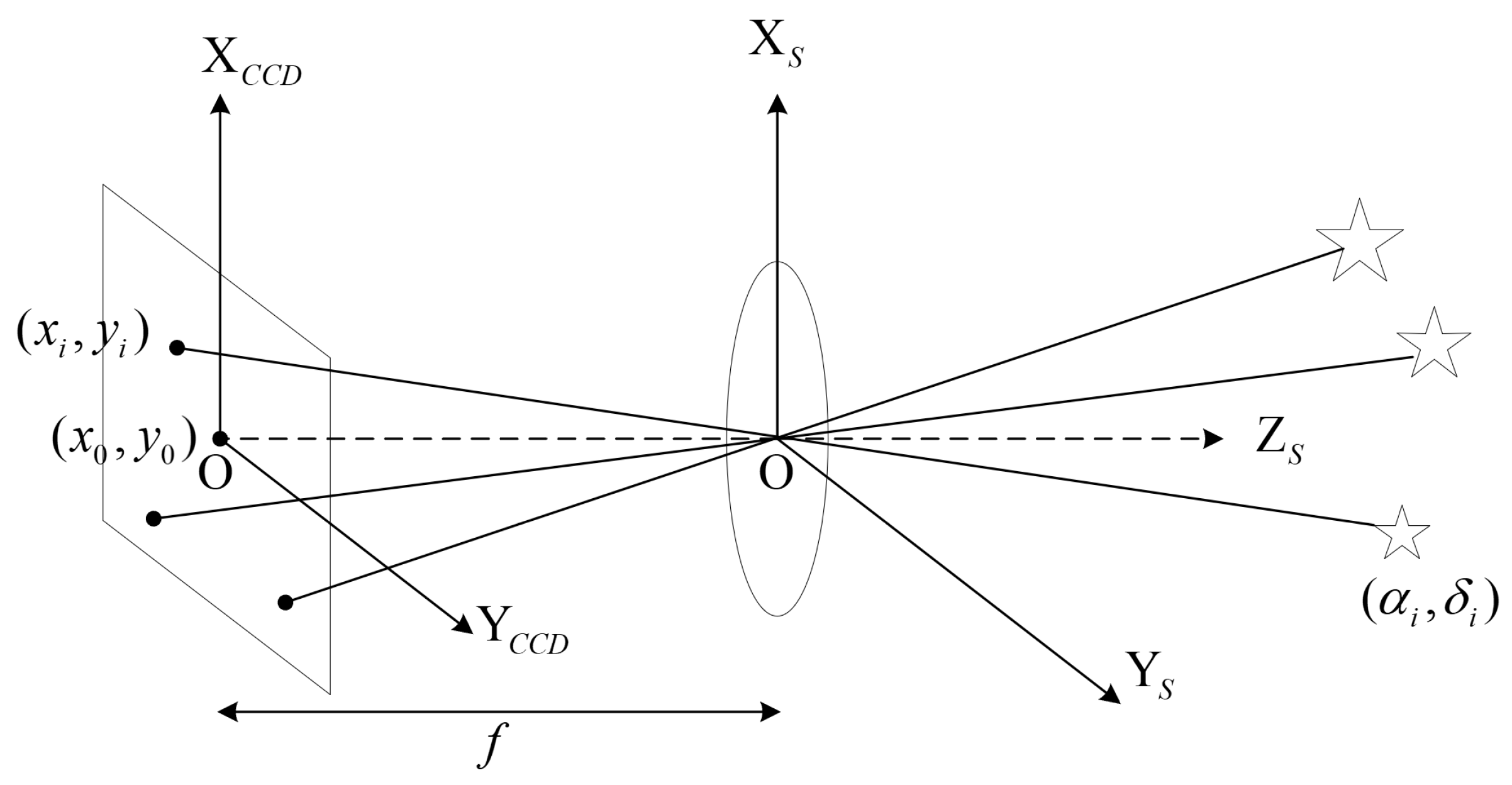
According to the ideal pinhole imaging model, there should be a one-to-one correspondence between a star vector in the star catalog and a star vector in the camera/star sensor coordinate system. As shown in Figure 3, in the instantaneous celestial coordinate system of J2000, the declination and right ascension of the -th star are denoted by . The observation vector can be expressed as follows:
After imaging, the coordinates of the -th star in the star map coordinate system O-XCCDYCCD are , and the measurement vector converted to the camera/star sensor coordinate system O-XsYsZs can be expressed as follows:
where is the focal length of the camera/star sensor’ optical lens, and is the intersection point between the optical axis of the lens and the image plane. When the camera/star sensor in the J2000 system is known and expressed as a certain attitude matrix , the star’s measurement vector and its observation vector are related as follows:
when using the TRIAD algorithm, only two stars are needed to obtain the attitude matrix . However, multiple stars are generally recognized in the field of view of a camera/star sensor and redundant observations are established for the multiple stars. The determination of the satellite triaxial attitude may be considered as equivalent to Wahba’s problem [38] and can be expressed as follows:
where is the minimum loss function, and is the weighting factor. The purpose is to find a that minimizes the sum of the residual errors for all the stars (). Using the Davenport q-method, quaternion estimator (QUEST) method, singular value decomposition (SVD) method, fast optimal attitude matrix (FOAM) method, estimator of the optimal quaternion (ESOQ) method, and other algorithms [39], the attitude can be obtained in quaternions such as . Thus, the attitude rotation matrix can be expressed as follows:
2.5.2. Aberration Correction
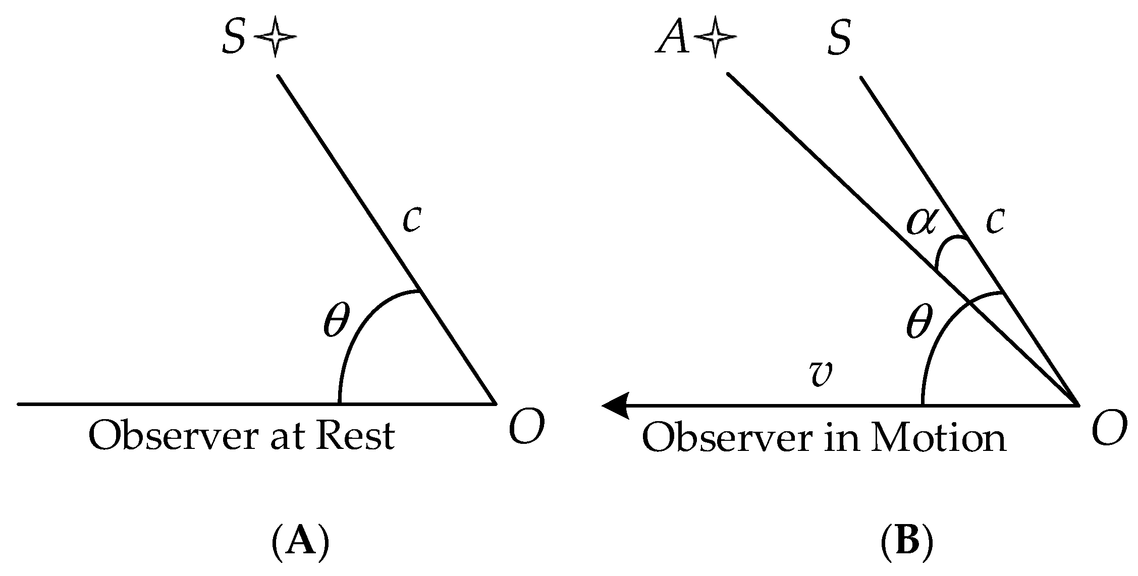
In celestial body observation, the observation angle of an observer at rest and an observer in motion observed in the same celestial body are inconsistent. This phenomenon is referred to as the aberration effect. As shown in Figure 4A, when the observer is at rest, the star is located in the direction S. When the observer is moving, the star light source observed by the observer always shifts toward the destination point, which is in the direction A, as shown in Figure 4B.
The angle between the directions of the motion and the light source is denoted by , while is the aberration migration angle, is the observer’s motion speed, and is the speed of light. The aberration formula can therefore be expressed as follows:
The aberration effect is similar to a bias with a magnitude and direction dependent on the relative velocity between the observer and the observed object. Because Luojia 1-01 moves fast in the true of date (TOD, an inertial coordinate system defined at the correct epoch) coordinate system, the aberration effect must be considered. In the case of star or stellar observation, the earth’s orbital motion must also be considered. The size of the aberration rate of the satellite is related to the satellite velocity within the heliocentric inertial frame and the optical axis orientation of the observation instrument [15,40,41]. Because the three coordinate axes of the heliocentric or geocentric celestial coordinate system of J2000 have the same direction, the satellite velocity can be directly added as follows:
where is the resultant velocity of the satellite in the heliocentric celestial coordinate system of J2000, is the velocity of the satellite in the geocentric celestial coordinate system of J2000, and is the velocity of the earth in the heliocentric celestial coordinate system of J2000. The optical axis direction of the camera in the celestial coordinate system of J2000 is denoted by , and the deviation angle caused by an aberration is defined as follows:
According to the deviation angle and rotation axis, the transformation relation can be expressed in the form of quaternions using the axis/angle formula. The aberration correction quaternion is expressed as follows:
where indicates normalization after cross product. Thus, the revised quaternion of the camera/star sensor can be obtained from the initial quaternion and time , as follows:
2.6. Calibration of Camera-Star Sensor Installation
The least squares method was used to calibrate the installation between the star sensor and camera. For example, under the inertia frame of J2000 at time , the attitude rotation matrix of the star sensor is , the attitude rotation matrix of the camera is , and the camera-to-the star sensor installation matrix is . The following formula is thus established:
where can be expressed as follows:
where are the nine parameters of the camera/star sensor rotation matrix at time , similar to . For multiple measurements, the least squares solution of can be obtained. For the values observed between times and , the installation parameter between the camera and star sensor can be expressed as follows:
where
A similar expression can be obtained for .
2.7. Geometric Positioning Model and Verification Methods
2.7.1. Verification Model Using Ground Reference
The camera-star sensor installation obtained by calibration was used to construct a ground geometric positioning model, and the image positioning accuracy without using GCPs was verified by the following formula:
where is the camera-star sensor installation parameter; denotes the position of any point in the WGS84 coordinate system; denotes the center of the satellite in the WGS84 coordinate system is the scale factor determined by the orbital altitude; is the matrix of the coordinate rotation from J2000 to WGS84, obtained by combining the EOP parameters with the imaging time is the attitude of the inertial system measured by the star sensor; denotes the numbers of row and column pixels in the image; denotes the center of the focal plane of the camera; and is the focal length of the camera.
For verification using a ground reference, all the parameters on the right side of Equation (22) can be acquired through the satellite platform. Hence, the ground coordinates of any point in the image yet to be verified can be calculated using Equation (22). By comparison with the coordinates of the homonymy point in the reference image, the positioning accuracy can be determined. However, if in Equation (22) is known, the coordinates can be acquired as GCPs from the corresponding homonymy point. The precision of can thus be calculated using the equation, which is the basic equation for GCP-based calibration.
2.7.2. Verification Model Using Moon Reference
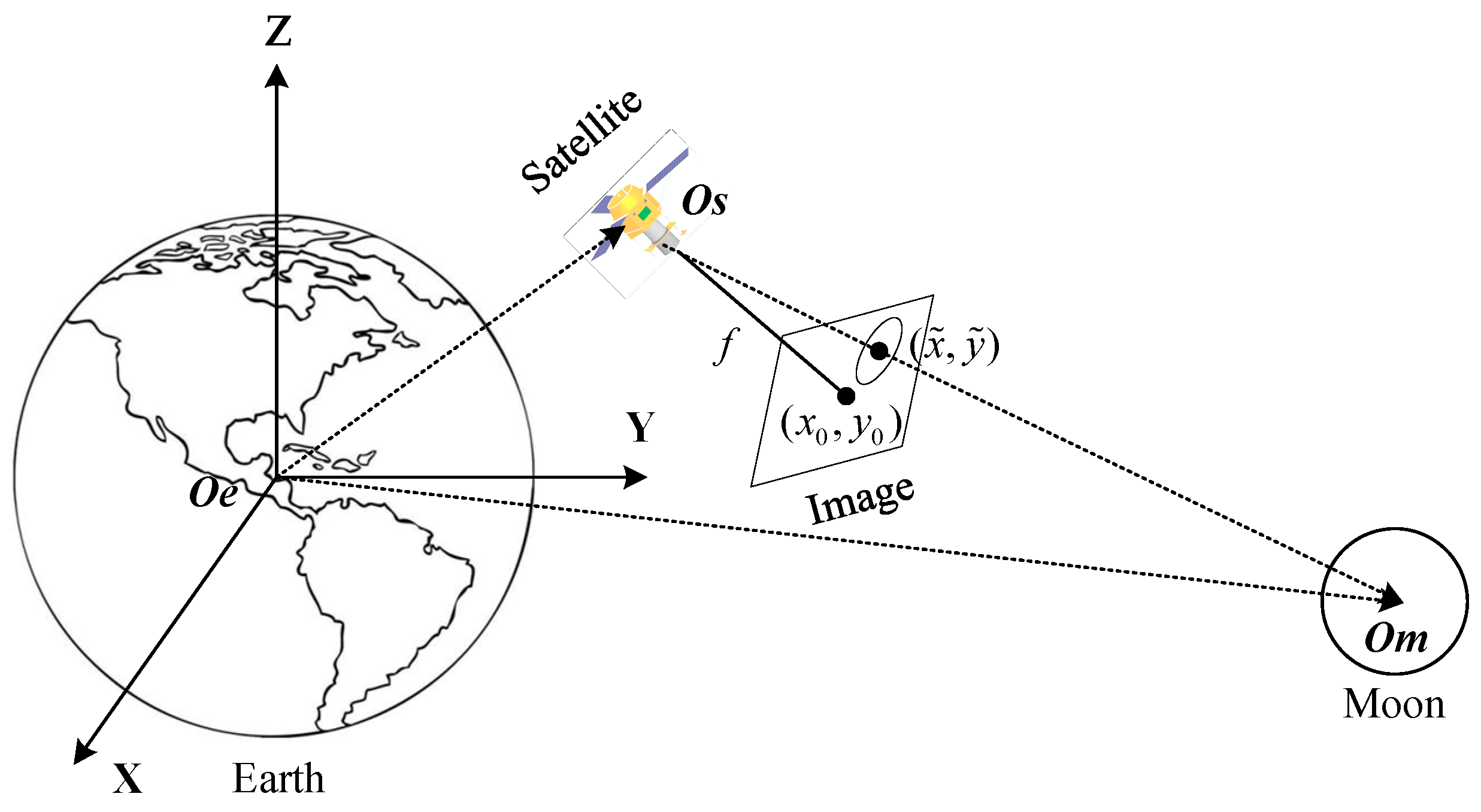
As shown in Figure 5, the centers of the Earth, , satellite, and Moon, , have the following geometric relationship in the J2000 coordinate system:
that is,
where denotes the coordinates of the Moon center in the J2000 coordinate system. The other notations are as previously described for the ground geometric positioning model.
When using Moon reference for verification, the coordinates of the Moon center can be acquired using the Ephemeris DE421 and the imaging time. Other parameters can also be acquired through the satellite platform. Hence, using the model, the coordinates of the Moon center can be obtained as , and those of the actual Moon center in the image as , enabling the determination of the positioning accuracy.
3. Results
3.1. Calibration and Verification of the Camera-Star Sensor Installation
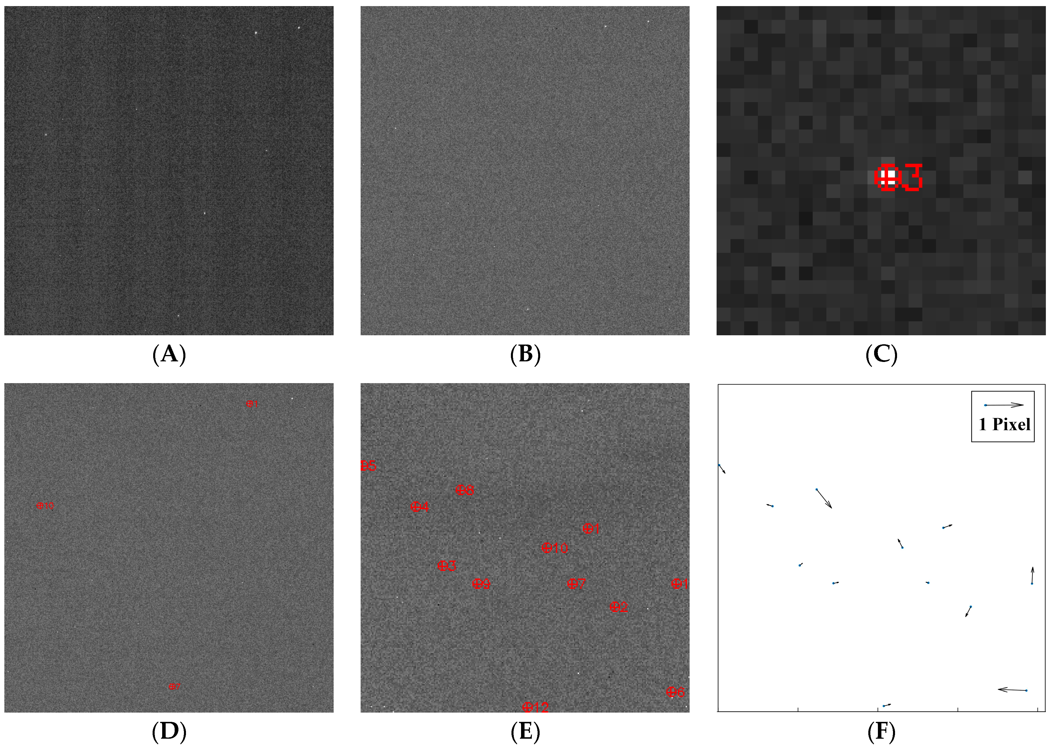
Figure 6 shows the results at various steps of processing the star map. Figure 6A shows the first scene of the star map acquired by Luojia 1-01. Stripe noise is visible in the original image. Figure 6B shows the star map after background denoising, while Figure 6C shows the extraction of a star, with the center at the centroid of the star point. The position of each star in the star map is acquired after this step. Figure 6D shows the result of the recognition using the SAO star catalog, while Figure 6E shows the star extraction result for the first star map. Owing to the sensitive magnitude of the Luojia 1-01 camera (less than fourth magnitude), only twelve stars were extracted from the first scene. There were insufficient control points for inner element calibration of the camera, though sufficient for the calibration of exterior elements such as the installation parameter. After this step, the coordinates of each star in the J2000 coordinate system was acquired. Combining the results in Figure 6C,E, the installation parameter between the camera and star sensor was acquired by the calibration method, as previously described.
After compensation of the installation parameter, the new position of each star in the star map was calculated. The difference between the new position of each star and the previously extracted position is the calibration error. The error includes the star extraction error, star proper motion error, aberration correction error, and camera inner element error. The calibration errors of the different stars are shown in Figure 6F. The root mean square (RMS) error was determined to be 0.4 pixels, which meets the requirements for installation calibration between the camera and star sensor of Luojia 1-01. At the same time, the error reflected that the consistency of each pixel in Luojia-1’s camera is so fine that four GCPs or even one GCP were used could reflect the absolute positioning accuracy when verification.
3.2. Verification of Camera-Star Sensor Installation
3.2.1. Verification Using Ground Reference
In this experiment, two groups of installation parameters after calibration were compared and verified. The groups of parameters are as follows:
- Installation parameters acquired by the star-based method, as shown in Figure 1B. The experimental images were obtained in the star imaging mode of Luojia 1-01 on 1 April 2019.
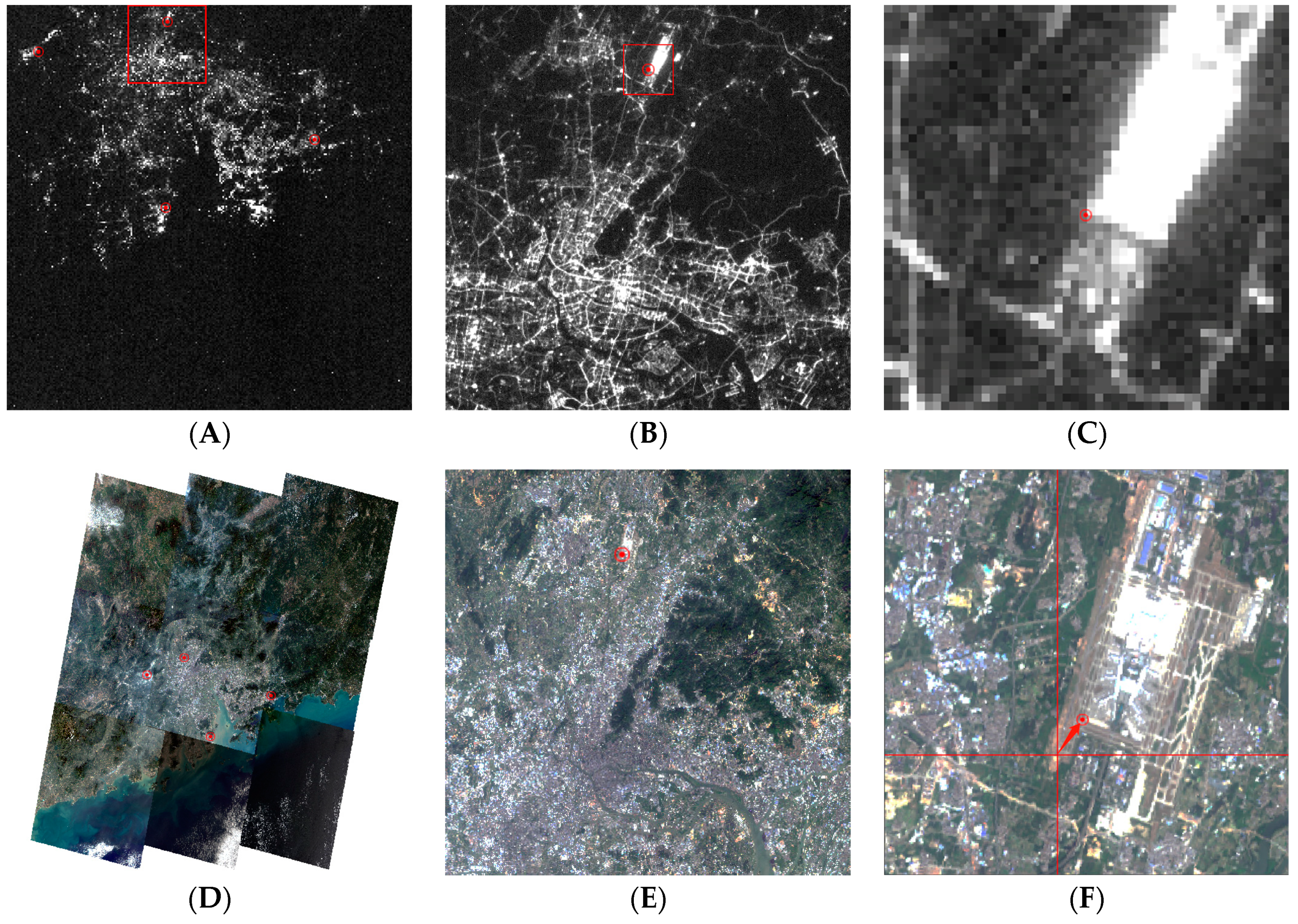
Figure 7 shows the relationship between the nighttime images obtained by Luojia 1-01 and the reference daytime images of differing scales obtained from Landsat. Four homonymy points were identified, as shown in Figure 7A,D. The coordinates acquired from Figure 7D were considered as the CPs of the nighttime images. The positions of the four points in the nightlight images were calculated after compensation of the installation parameter using the GCP-based method (Equation (22)) or star-based method. Figure 7B,E respectively show nightlight and daytime images of Guangzhou City. The red circles in the figures indicate homonymy points. The position (latitude and longitude) of the red circle in Figure 7C, calculated after compensation of the installation parameter, is at the cross hairs point in Figure 7F. The length of the arrow in the figure represents the positioning accuracy. The overall statistical results of positioning accuracy are presented in Table 3.
3.2.2. Verification Using Moon Reference
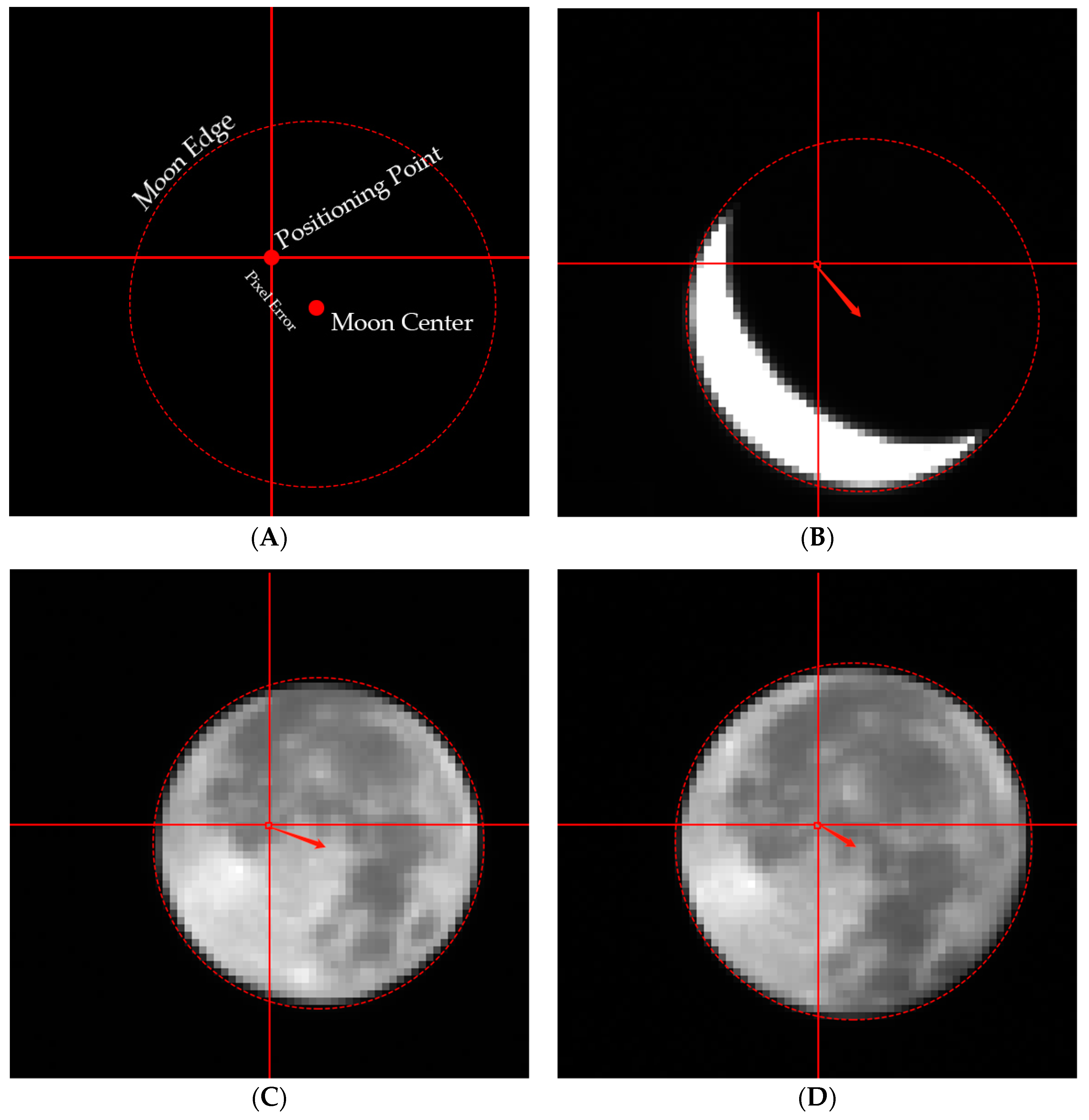
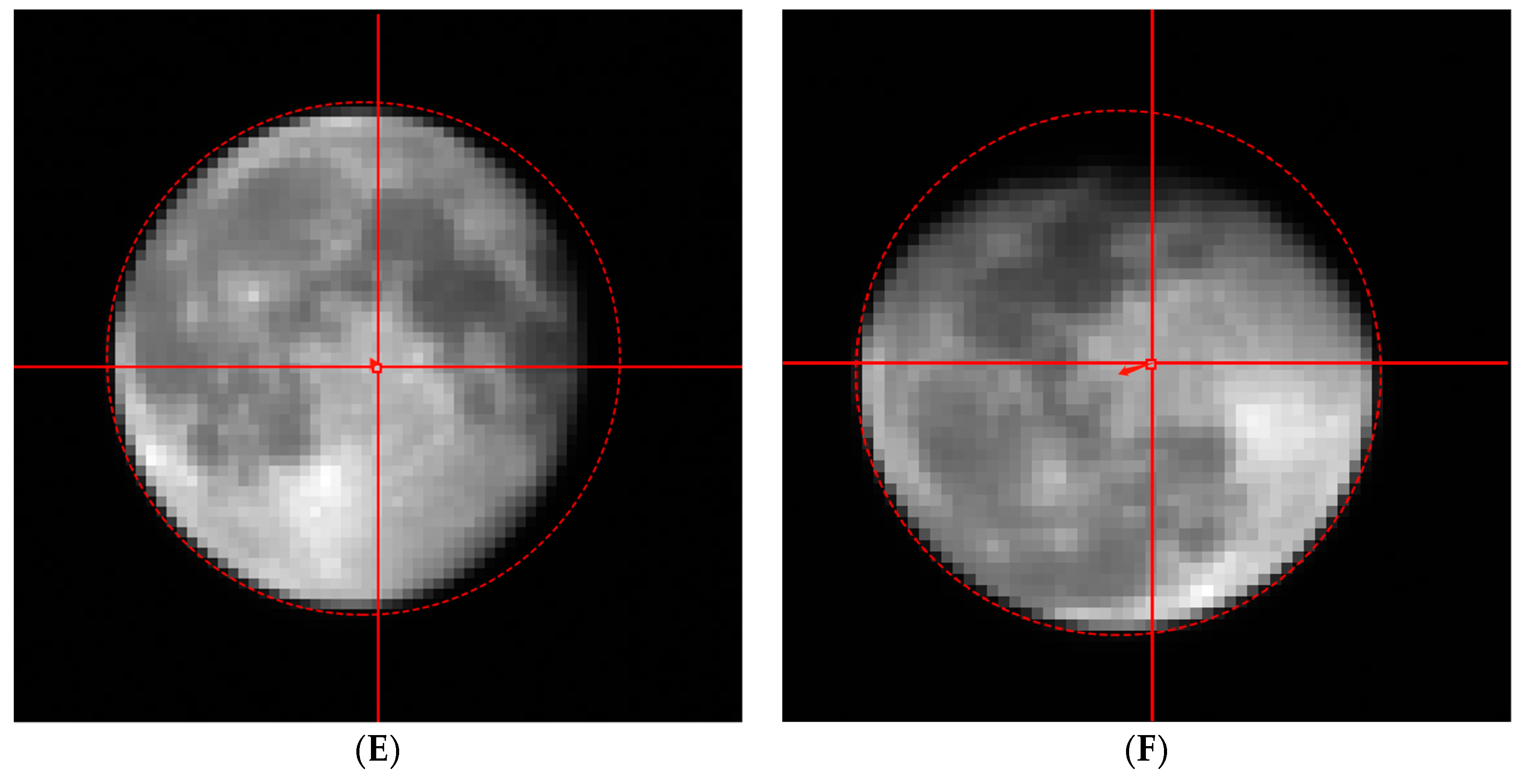
In the use of Moon reference for the verification, the laboratory measurement parameter, conventional GCP-based calibration parameter, and proposed star-based calibration parameter were used to construct the Moon geometric positioning model with the aid of Equation (24). Based on the Ephemeris data DE421 containing the position of the Moon, the positioning model was used to calculate the Moon position in the Luojia 1-01 image. By comparing the result with the actual extracted barycentric position of the Moon in the image, the positioning accuracy was determined. The overall positioning accuracy results for the proposed star-based calibration method are presented in Figure 7. The cross hairs point indicates the Moon center in the image, calculated by the positioning model, while the end of the arrow indicates the Moon center. The Sobel-Zernike operator is used to detect the edge of Moon, and searching algorithm based on circularity detection is used to find the Moon edge points for extracting the Moon center [42].
Figure 8A illustrates the Moon positioning accuracy, with the length of the arrow representing the positioning error of the Moon center. Figure 8B–F show five Moon center offset conditions. Because the images were obtained at different times, waxing and waning of the Moon occurred. Moreover, although the Moon was not full, the Moon center could still be accurately determined. The Moon positioning accuracies of the three calibration methods are presented in Table 4.
4. Discussion
As can be observed from Table 3 regarding the two images obtained on cumulative day 241, the positioning accuracy is approximately 900 m on the ground for both the GCP-based and Star-based methods. Regarding the two images obtained on cumulative day 282, the calibration parameter obtained through the star-based method affords a positioning accuracy of approximately 5–6 pixels on the image, and approximately 700 m on the ground. The RMS value indicated an accuracy within 800 m for star-based methods, which are comparable with the positioning accuracy of the GCP-based method.
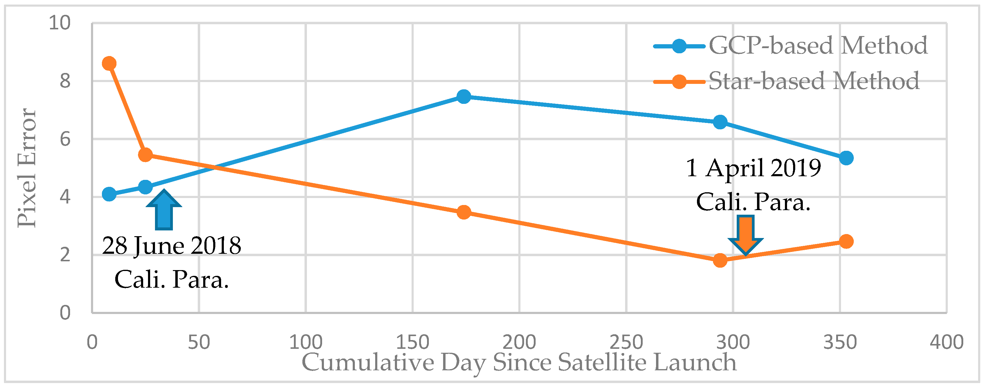
As can be observed from Table 4, before the calibration of the star sensor/camera in orbit, the geometric positioning error only reaches approximately 80 pixels, when only the laboratory calibration parameters are used. This implies a ground positioning accuracy of 80 × 129 m ≈ 10 km. After GCP-based calibration, the positioning accuracy is approximately 6 pixels on the image, corresponding to approximately 780 m on the ground. The star-based calibration images were captured on 1 April 2019, which is far from the data cumulative days 8 and 25, for which it afforded positioning accuracies of 700–1000 m. However, for the relatively close data cumulative day 174, the positioning accuracy is approximately 450 m. When the time difference between the calibration date and the data cumulative day is only approximately one week (cumulative day 294), the positioning accuracy reaches 235 m, or approximately 1.8 pixels. The positioning accuracy deteriorates with further increase of the cumulative day, being 2.46 pixels for cumulative day 353, which is about 50 days after the calibration date.
It is obvious from Figure 9 that a combination of the GCP-based and star-based calibration methods tends to improve the positioning accuracy when the Moon center changes, with the accuracy further increasing with decreasing time interval between the verification and calibration dates. Obviously, the Luojia 1-01 could be suggested a star-based calibration once a month which will maintain the positioning accuracy of less than three pixels. Considering that the positioning accuracy of optical satellites generally decreases over an extended time, the method developed in this study enables independent completion of the camera and star sensor calibration. Moreover, there is no strict satellite maneuverability requirement because the camera can be pointed to an arbitrary star. In other words, the satellite does not need to execute any special maneuver during the imaging besides maintaining its inertial motion. The calibration frequency depends on the required positioning accuracy of the satellite, and the geometric positioning remains good over an extended time. Compared with the ground calibration method, the requirement for control points in the proposed method is greatly reduced. The utilized control points are automatically obtained from stars, affording the additional advantage of significantly increased calibration speed.
5. Conclusions
Stellar photography was used to develop a method for calibrating the installation between the camera and star sensor of a satellite. The proposed method involves star extraction, recognition, aberration correction, and attitude determination. Experimental results demonstrated that the calibration accuracy was comparable with that of GCP-based methods. The proposed method was verified by using it to position the center of the Moon. It was observed that the shorter the time interval between the calibration and verification images, the higher the uncontrolled positioning accuracy.
The proposed calibration method can also be integrated with in-orbit processing to perform the calibration processes during the non-working hours of the satellite. Compared with the GCP-based method, the proposed method has significant advantages, including a broad imaging time and location range, which facilitate a high calibration frequency. The method offers a new approach to the geometric calibration of optical satellites. In its present demonstration, images of twelve stars were acquired and used to calibrate the installation parameters between the satellite’s camera and star sensor, which are external elements. The imaging of more stars would require a higher sensitivity level of the star magnitude. Further study is planned to apply the proposed method to the calibration of the internal elements of the camera for other high-resolution satellite.
Author Contributions
Z.G. and Y.J. conceived and designed the experiments; Z.L. provided the data; Z.G. and J.W. performed the experiments; Z.G., Y.J., and G.Z. analyzed the data; Y.J. contributed the analysis tools; Z.G. and Y.J. wrote the paper.
Funding
This work was supported by the Key Research and Development Program of Ministry of Science and Technology (Grant No. 2016YFB0500801), National Natural Science Foundation of China (Grant Nos. 41971412, 41901400, 91538106, 41501503, 41601490, and 41501383), National High Resolution Earth Observation Foundation (11-Y20A12-9001-17/18)
Acknowledgments
The authors are also grateful for the constructive comments and suggestions of the manuscript reviewers. We would like to thank Editage (www.editage.cn) for English language editing. The Software Routines used in the study were obtained from the IAU SOFA Collection (© International Astronomical Union Standards of Fundamental Astronomy, http://www.iausofa.org).
Conflicts of Interest
The authors declare no conflict of interest.
References
- Haines, B.; Desai, S.; Willis, P.; Bertiger, W.; Munson, T. Precise orbit determination for Jason-1: GPS and the 1-cm challenge. In Proceedings of the EGS-AGU-EUG Joint Assembly-1, Nice, France, 6–11 April 2003. [Google Scholar]
- Luthcke, S.B.; Zelensky, N.P.; Rowlands, D.D.; Lemoine, F.G.; Williams, T.A. The 1-Centimeter Orbit: Jason-1 Precision Orbit Determination Using GPS, SLR, DORIS, and Altimeter Data Special Issue: Jason-1 Calibration/Validation. Mar. Geod. 2003, 26, 399–421. [Google Scholar] [CrossRef]
- Wu, Q.B.; Zhao, C.M.; Zhu, G.B. Rapid Precision Orbit Determination Based on Dual-Frequency GPS Receiver for ZY3-02 Satellite. J. Geod. Geodyn. 2018, 38, 73–77. [Google Scholar]
- Tadono, T.; Shimada, M.; Murakami, H.; Takaku, J. Calibration of PRISM and AVNIR-2 Onboard ALOS “Daichi”. IEEE Trans. Geosci. Remote. Sens. 2009, 47, 4042–4050. [Google Scholar] [CrossRef]
- Takaku, J.; Tadono, T. PRISM On-Orbit Geometric Calibration and DSM Performance. IEEE Trans. Geosci. Remote. Sens. 2009, 47, 4060–4073. [Google Scholar] [CrossRef]
- Iwata, T. Advanced land observing satellite (ALOS): On-orbit status and platform calibration. In Proceedings of the 2007 IEEE International Geoscience and Remote Sensing Symposium, Barcelona, Spain, 23–27 July 2007; pp. 3583–3588. [Google Scholar]
- Amberg, V.; Dechoz, C.; Bernard, L.; Greslou, D.; De Lussy, F.; Lebègue, L. In-flight attitude perturbances estimation: Application to PLEIADES-HR satellites. Earth Obs. Syst. XVIII 2013, 8866, 886612. [Google Scholar]
- Jiang, Y.; Zhang, G.; Tang, X. High Accuracy Geometric calibration of ZY-3 Three-line Images. Acta Geod. Cartogr. Sin. 2013, 42, 523–529. [Google Scholar]
- Wang, T.; Zhang, G.; Li, D.; Tang, X.; Jiang, Y.; Pan, H.; Zhu, X.; Fang, C. Geometric Accuracy Validation for ZY-3 Satellite Imagery. IEEE Geosci. Remote Sens. Lett. 2014, 11, 1168–1171. [Google Scholar] [CrossRef]
- Li, D. China’s First Civilian Three-line-array Stereo Mapping Satellite: ZY-3. Acta Geod. Cartogr. Sin. 2012, 41, 317–322. [Google Scholar]
- Cutler, B. Pléiades 1B and SPOT 6 Image Quality status after commissioning and 1st year in orbit. In Proceedings of the2014 Joint Agency Commercial Imagery Evaluation (JACIE) Workshop, Louisville, KY, USA, 26–28 March 2014. [Google Scholar]
- Hu, F.; Gao, X.M.; Li, G. Dem Extraction from Worldview-3 Stereo-Images and Accuracy Evaluation. ISPRS Int. Arch. Photogramm. Remote. Sens. Spat. Inf. Sci. 2016, XLI-B1, 327–332. [Google Scholar] [CrossRef]
- Bresnahan, P.; Brown, E.; HenryVazquez, L. WorldView-3 Absolute Geolocation Accuracy Evaluation. In Proceedings of the Joint Agency Commercial Imagery Evaluation Workshop, Tampa, FL, USA, 5–7 May 2015. [Google Scholar]
- Longbotham, N.W.; Pacifici, F.; Malitz, S.; Baugh, W.; Camps-Valls, G. Measuring the Spatial and Spectral Performance of WorldView-3. In Proceedings of the Fourier Transform Spectroscopy and Hyperspectral Imaging and Sounding of the Environment, Lake Arrowhead, CA, USA, 1–4 March 2015. [Google Scholar]
- Greslou, D.; De Lussy, F.; Delvit, J.M.; Dechoz, C.; Amberg, V. Pleiades-Hr Innovative Techniques For Geometric Image Quality Commissioning. ISPRS Int. Arch. Photogramm. Remote. Sens. Spat. Inf. Sci. 2012, XXXIX-B1, 543–547. [Google Scholar] [CrossRef]
- Lebegue, L.; Greslou, D.; Delussy, F.; Fourest, S. PLEIADES-HR image quality commissioning. In Proceedings of the ISPRS—International Archives of the Photogrammetry, Remote Sensing and Spatial Information Sciences 2012, Melbourne, Australia, 25 August–1 September 2012. [Google Scholar]
- Philippe Kubik, L.L.S.F. First in-flight results of Pleiades 1A innovative methods for optical calibration. In Proceedings of the International Conference on Space Optics, Ajaccio, Corse, France, 9–12 October 2012. [Google Scholar]
- Fourest, S.; Kubik, P.; Lebègue, L.; Dechoz, C.; Lachérade, S.; Blanchet, G. Star-Based Methods for Pleiades Hr Commissioning. ISPRS Int. Arch. Photogramm. Remote. Sens. Spat. Inf. Sci. 2012, XXXIX-B1, 531–536. [Google Scholar] [CrossRef]
- Jiang, Y.; Xu, K.; Zhang, G. A Method of Exterior Auto Calibration for Linear CCD Array Pushbroom Optical Satellites. J. Tongji Univ. Nat. Sci. 2016, 44, 1266–1271. [Google Scholar]
- Jiang, Y.; Zhang, G.; Wang, T.; Li, D.; Zhao, Y. In-Orbit Geometric Calibration Without Accurate Ground Control Data. Photogramm. Eng. Remote. Sens. 2018, 84, 485–493. [Google Scholar] [CrossRef]
- Iwata, T.; Uo, M.; Kawahara, T. Attitude Determination Using Repeated Smoothing with Sequential Rate Bias and Attitude Estimation. In Proceedings of the Aiaa Guidance, Navigation, & Control Conference, Toronto, ON, Canada, 2–5 August 2010. [Google Scholar]
- Iwata, T.; Hoshino, H.; Yoshizawa, T.; Kawahara, T. Precision Attitude Determination for the Advanced Land Observing Satellite (ALOS): Design, Verification, and On-Orbit Calibration. In Proceedings of the Guidance, Navigation and Control Conference, Hilton Head, CA, USA, 20–23 August 2007. [Google Scholar]
- Zhang, G.; Guan, Z. Primary research on Reliability of satellite imaging quality. Geomat. Inf. Sci. Wuhan Univ. 2018, 43, 1954. [Google Scholar]
- Zhang, K.; Zhong, X.; Zhang, G.; Li, D.; Su, Z.; Meng, Y.; Jiang, Y. Thermal Stability Optimization of the Luojia 1-01 Nighttime Light Remote-Sensing Camera’s Principal Distance. Sensors 2019, 19, 990. [Google Scholar] [CrossRef]
- Guan, Z.; Jiang, Y.; Zhang, G. Vertical Accuracy Simulation of Stereo Mapping Using a Small Matrix Charge-Coupled Device. Remote Sens. 2018, 10, 29. [Google Scholar] [CrossRef]
- Zhang, G.; Wang, J.; Jiang, Y.; Zhou, P.; Zhao, Y.; Xu, Y. On-Orbit Geometric Calibration and Validation of Luojia 1-01 Night-Light Satellite. Remote. Sens. 2019, 11, 264. [Google Scholar] [CrossRef]
- Zhong, X.; Su, Z.; Zhang, G.; Chen, Z.; Meng, Y.; Li, D.; Liu, Y. Analysis and Reduction of Solar Stray Light in the Nighttime Imaging Camera of Luojia-1 Satellite. Sensors 2019, 19, 1130. [Google Scholar] [CrossRef]
- Myers, J.R.; Sande, C.B.; Miller, A.C.; Warren, W.H., Jr.; Tracewell, D.A. VizieR Online Data Catalog: SKY2000 Catalog, Version 3 (Myers+ 2000). VizieR Online Data Catalog, 2001; 5105. [Google Scholar]
- Altamimi, Z.; Collilieux, X.; Legrand, J.; Garayt, B.; Boucher, C. ITRF2005: A new release of the International Terrestrial Reference Frame based on time series of station positions and Earth Orientation Parameters. J. Geophys. Res. Space Phys. 2007, 112, 112. [Google Scholar] [CrossRef]
- Folkner, W.M.; Williams, J.G.; Boggs, D.H. The Planetary and Lunar Ephemeris DE 421. Interplanet. Netw. Prog. Rep. 2009, 178, 1–34. [Google Scholar]
- Landsat Data Access|Landsat Missions. Available online: https://landsat.usgs.gov/landsat-data-access (accessed on 16 August 2018).
- Yuan, Y.; Zheng, Y.; Du, L. High-Accuracy Centroid Algorithm of Star Points. J. Geomat. Sci. Technol. 2012, 29, 122–126. [Google Scholar]
- Zhang, G.; Li, L.; Jiang, Y.; Shen, X.; Li, D. On-Orbit Relative Radiometric Calibration of the Night-Time Sensor of the LuoJia1-01 Satellite. Sensors 2018, 18, 4225. [Google Scholar] [CrossRef]
- Liang, B.; Long, H.; Zhang, T. Research status and development tendency of star tracker technique. Chin. Opt. 2016, 9, 16–29. [Google Scholar] [CrossRef]
- Padgett, C.; Kreutz-Delgado, K.; Udomkesmalee, S. Evaluation of Star Identification Techniques. J. Guid. Control Dyn. 1997, 20, 259–267. [Google Scholar] [CrossRef]
- Liebe, C. Pattern recognition of star constellations for spacecraft applications. IEEE Aerosp. Electron. Syst. Mag. 1992, 7, 34–41. [Google Scholar] [CrossRef] [Green Version]
- Zhang, R. Design and Realization of Star recognition Algorithms Based on CCD Star Tracker. Master’s Thesis, the Information Engineering University, Zhengzhou, Henan, China, April 2007. [Google Scholar]
- Shuster, M.D. The generalized Wahba problem. J. Astronaut. Sci. 2006, 54, 245–259. [Google Scholar] [CrossRef]
- Markley, F.L.; Crassidis, J.L. Fundamentals of Spacecraft Attitude Determination and Control; Springer Science and Business Media LLC: Berlin/Heidelberg, Germany, 2014. [Google Scholar]
- Greslou, D.; De Lussy, F.; Montel, J. Light Aberration Effect in HR Geometric Model. ISPRS Int. Arch. Photogramm. Remote. Sens. Spat. Inf. Sci. 2008, XXXVII-B1, 859–864. [Google Scholar]
- Lai, Y.; Gu, D.; Liu, J. In-Flight Systematic Error Analysis and Calibration for Star Tracker/Gyro. In Proceedings of the 3rd China High Resolution Earth Observation Conference, Beijing, China, 20–21 December 2013. [Google Scholar]
- Pu, J.; Zheng, Y.; Li, C.; Zhan, Y.; Chen, S.; He, D. A Moon Image Center Extraction Algorithm Adapted to Moon Phrase Change. J. Geomat. Sci. Technol. 2017, 34, 461–465. [Google Scholar]
Figure 1.
Sketch map of calibrating by photographing stars. (A) GCP-based method; (B) Star-based mehtod.
Figure 1.
Sketch map of calibrating by photographing stars. (A) GCP-based method; (B) Star-based mehtod.

Figure 2.
Flow chart of camera and star sensor calibration and verification for Luojia-1.

Figure 3.
Principle of the camera/star sensor stars observation.

Figure 4.
Principle of aberration effect. (A) An observer at rest; (B) An observer in motion

Figure 5.
Moon geometric model.

Figure 6.
Star map processing results. (A) original star map with cropping, size of 400 × 400 pixels; (B) star map after background denoising, size of 400 × 400 pixels; (C) star point extraction result, size of 50 × 50 pixels; (D) star recognition result, size of 400 × 400 pixels; (E) recognition result of the first scene, size of 2048 × 2048 pixels; (F) calibration errors after compensation of the installation parameter, size of 2048 × 2048 pixels.

Figure 7.
Luojia 1-01 images and reference daytime images of under different scale (A–C are Luojia 1-01 images, and zoom levels increase gradually; D–F are daytime reference images acquired from 9 scenes of Landsat-8; A,D: Guangdong–Hong Kong–Macao Greater Bay Area, B,E: Guangzhou, C,F: Guangzhou Baiyun Airport.).

Figure 8.
Positioning bias of moon center under the calculation of stars-based calibration method. (A) Illustration of Moon positioning accuracy; (B) cumulative day 8 (10 June 2018); (C) cumulative day 25 (27 June 2018); (D) cumulative day 174 (23 November 2018); (E) cumulative day 294 (23 March 2019); (F) cumulative day 353 (21 May 2019).


Figure 9.
Positioning accuracy change trend with cumulative day and calibrate date.


Table 1.
Luojia 1-01 satellite parameters.
| Parameter | Value/Description |
|---|---|
| Orbit type | Sun-synchronous orbit |
| Orbit height | 645 km |
| Ground sampling distance | 129 m (sub satellite point) |
| Ground swath | 264 km × 264 km |
| Spectral range | 480–800 nm |
| Camera focal length | 55 mm |
| Camera pixel size | 2048 × 2048 |
| Camera detector size | 11 μm × 11 μm |
| Camera field of view (FOV) | 32.3° |
| Star sensor sampling frequency | 1 Hz |
| Star sensor FOV | 90° |
| Imaging mode | Nightlight mode/daytime mode/Moon mode/star mode |
| Attitude maneuverability | Pitch axis > 0.9°/s |
| Total satellite mass | < 20 kg |
| Envelope size | 520 mm × 870 mm × 390 mm |
Table 2.
Luojia 1-01 experiment data.
| Cumulative Day | Imaging Start Time | Imaging Mode | Imaging Angle/° (Roll, Pitch, Yaw) |
|---|---|---|---|
| 8 | 2018-06-10T08:04:10.65 | Moon mode | −84.81, −20.98, −13.07 |
| 25 | 2018-06-27T23:43:24.15 | Moon mode | −85.09, −13.96, 18.77 |
| 26 | 2018-06-28T11:20:46.18 | Daytime mode | 1.06, −12.62, 5.42 |
| 174 | 2018-11-23T22:45:05.29 | Moon mode | −120.84, −28.84, 29.07 |
| 241 | 2019-01-29T14:56:37.23 | Nightlight mode | −11.39, −0.37, −1.56 |
| 241 | 2019-01-29T14:57:02.26 | Nightlight mode | −11.39, −0.37, −1.56 |
| 282 | 2019-03-11T14:56:18.15 | Nightlight mode | −7.55, −0.21, −1.69 |
| 282 | 2019-03-11T14:56:38.17 | Nightlight mode | −7.53, −0.23, −1.68 |
| 294 | 2019-03-22T17:40:19.18 | Moon mode | −141.02, −43.05, 53.39 |
| 303 | 2019-04-01T03:33:15.69 | Star mode | −98.13, −45.44, 15.71 |
| 353 | 2019-05-21T15:03:00.15 | Moon mode | 163.62, −44.94, 142.04 |
Table 3.
Positioning accuracy comparison of Luojia 1-01 nightlight images under two method.
| Cum. Day | Imaging Date | GCP-Based Method | Star-Based Method | ||
|---|---|---|---|---|---|
| Image (pixel) | Ground (m) | Image (pixel) | Ground (m) | ||
| 241 | 29 January 2019 | 6.3 | 820 | 6.5 | 850 |
| 241 | 29 January 2019 | 6.9 | 900 | 6.8 | 890 |
| 282 | 11 March 2019 | 5.3 | 690 | 4.3 | 560 |
| 282 | 11 March 2019 | 4.4 | 570 | 5.2 | 680 |
| RMS | 5.80 | 748 | 5.78 | 745 | |
Table 4.
Moon position under different calibration method.
| Cum. Day | Imaging Data | Calibration Method | Calculated Moon Center (Pixel) | Measured Moon Center (Pixel) | Positioning Accuracy | |
|---|---|---|---|---|---|---|
| Pixel | Ground/m | |||||
| 8 | 10 June 2018 | Lab. | (1133.54, 679.72) | (1105.25, 606.67) | 78.34 | 10183.76 |
| GCPs | (1102.25, 603.89) | 4.09 | 531.70 | |||
| Stars | (1099.96, 599.89) | 8.60 | 1117.94 | |||
| 25 | 27 June 2018 | Lab. | (438.85, 1054.01) | (411.07, 977.75) | 81.16 | 10551.10 |
| GCPs | (408.44, 981.20) | 4.34 | 563.96 | |||
| Stars | (405.75, 976.58) | 5.45 | 708.13 | |||
| 174 | 23 November 2018 | Lab. | (1050.06, 1001.15) | (1018.46, 918.70) | 88.30 | 11478.76 |
| GCPs | (1019.89, 926.02) | 7.46 | 969.59 | |||
| Stars | (1017.29, 921.97) | 3.47 | 451.49 | |||
| 294 | 23 March 2019 | Lab. | (1037.89, 972.96) | (1003.77, 892.53) | 87.37 | 11357.83 |
| GCPs | (1007.62, 897.87) | 6.58 | 855.81 | |||
| Stars | (1005.05, 893.81) | 1.81 | 235.33 | |||
| 353 | 21 May 2019 | Lab. | (1019.58,959.01) | (984.65,881.27) | 85.23 | 11079.90 |
| GCPs | (989.25,883.98) | 5.34 | 694.20 | |||
| Stars | (986.69,879.90) | 2.46 | 319.80 | |||
| RMS | Lab. | 84.16 | 10941.31 | |||
| GCPs | 5.71 | 742.32 | ||||
| Stars | 5.00 | 650.04 | ||||
© 2019 by the authors. Licensee MDPI, Basel, Switzerland. This article is an open access article distributed under the terms and conditions of the Creative Commons Attribution (CC BY) license (http://creativecommons.org/licenses/by/4.0/).
Share and Cite
MDPI and ACS Style
Guan, Z.; Jiang, Y.; Wang, J.; Zhang, G. Star-Based Calibration of the Installation Between the Camera and Star Sensor of the Luojia 1-01 Satellite. Remote Sens. 2019, 11, 2081. https://0-doi-org.brum.beds.ac.uk/10.3390/rs11182081
AMA Style
Guan Z, Jiang Y, Wang J, Zhang G. Star-Based Calibration of the Installation Between the Camera and Star Sensor of the Luojia 1-01 Satellite. Remote Sensing. 2019; 11(18):2081. https://0-doi-org.brum.beds.ac.uk/10.3390/rs11182081
Chicago/Turabian StyleGuan, Zhichao, Yonghua Jiang, Jingyin Wang, and Guo Zhang. 2019. "Star-Based Calibration of the Installation Between the Camera and Star Sensor of the Luojia 1-01 Satellite" Remote Sensing 11, no. 18: 2081. https://0-doi-org.brum.beds.ac.uk/10.3390/rs11182081
Note that from the first issue of 2016, this journal uses article numbers instead of page numbers. See further details here.