1. Introduction
The geometric accuracy of high-resolution optical remote sensing satellites without ground control points (GCPs) is influenced by factors such as the orbit determination error, attitude determination error, time measurement error, calibration error of the optical camera, and observation conditions [
1,
2,
3]. The attitude determination measures the orientation of the satellite in the
J2000 (Julian year 2000) celestial coordinate system and can be expressed by a transformation matrix [
4]. When the orbit altitude is 500 km, an attitude measurement error of 1″ can introduce a geometric error of 2.4 m. Thus, the attitude measurement error becomes a key factor influencing the geometric accuracy of high-resolution optical remote sensing satellites without GCPs [
5].
Currently, to improve the geometric accuracy, a high-resolution optical remote sensing satellite is usually equipped with star sensors as the attitude determination system (ADS), owing to its advantages in anti-jamming, resistance to drift with time, and higher measurement accuracy [
6,
7,
8]. The star sensor utilizes a light detector to gather lines of sight from two or more stars in space and calculates the transformation matrix from the ADS coordinate system to the
J2000 celestial coordinate system [
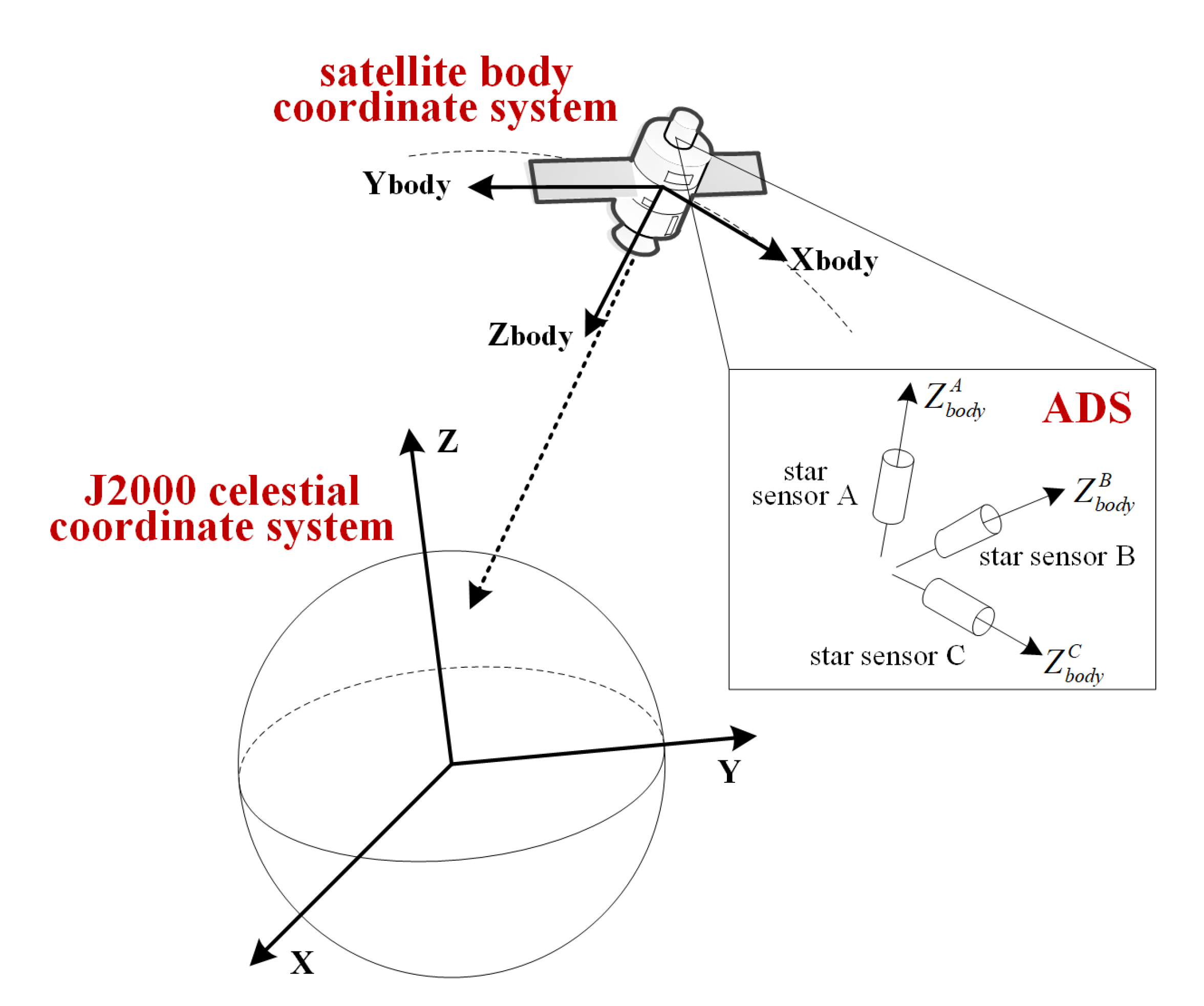
9]. Then, based on the installation parameters of the star sensor in the satellite body coordinate system, the orientation of the satellite body in the
J2000 celestial coordinate system can be obtained, as shown in
Figure 1. Generally, three star sensors are used to ensure the accuracy of the attitude determination. As influenced by the view angle of the optical satellite during imaging, some star sensors may be exposed to the sun, or the number and distribution of stars may be insufficient for a high-accuracy attitude determination. There are usually two star sensors working simultaneously, forming a variety of star sensor combination modes for precise attitude determination. These star sensors, which belong to a common combination mode, are denoted as conventional star sensors, i.e., star sensor B and star sensor C. The alternate star sensor is considered as the unconventional star sensor, and is denoted as star sensor A. The combined mode with star sensor B and star sensor C is considered as a conventional combined mode, whereas the combined modes with star sensor A and star sensor B or star sensor A and star sensor C are regarded as unconventional combined modes.
When the installation parameters of the star sensor in the satellite body coordinate system are measured exactly, the virtual body coordinate systems determined by the installation parameters of the different star sensor combination modes are consistent, and the orientation of the satellite body in the
J2000 celestial coordinate system can be calculated correctly. However, owing to vibrations and thermal shocks that arise during launch and orbit penetration process, there is a gap between the on-orbit actual installation parameters and the on-ground measured parameters [
10]. Therefore, the virtual body coordinate systems determined by the different star sensor combination modes are inconsistent, causing systematic errors in the precise attitude determinations of different combination modes [
11]. The on-orbit installation errors in star sensors seriously affect the geometric accuracy of the high-resolution optical remote sensing images, as the errors can reach hundreds of meters.
On-orbit calibration of the installation parameters in a multiple star sensors system is an effective approach for eliminating the inconsistency in different star sensor combination modes. Many researchers have focused on installation parameter calibration using a Kalman filter. Pittelkau proposed a calibration approach for an absolute installation parameter of a star sensor using an alignment Kalman filter (AKF). A U–D factorization was adopted to make the calibration method robust and flexible. The simulation results demonstrated the effects of miscalibration on a typical six-state on-orbit attitude estimation filter, and the performance of the AKF in estimating the star sensor installation parameters and gyro calibration parameters [
12]. Pittelkau then examined absolute and relative installation calibrations of a star sensor. The gyro was adopted as a body reference frame to calibrate the installation error of the star sensor using the AKF. The simulation results illustrated that the relative installation of the star sensor converged without ambiguity [
13]. Cao et al. selected a one star-sensor as a fiducial star-sensor [
14]. The relative installation parameter of the other star sensor was expanded into an extended Kalman filter (EKF) to improve the precision of the attitude in real time. Moreover, some researchers have calibrated installation parameters using a neural network. To improve the calibration accuracy under large installation angle errors, Zhang et al. presented a novel calibration approach using a regularized backpropagation neural network and achieved calibration without formula derivation and numerical calculation under both small and large installation angle errors [
15]. In the related area of inertial navigation systems (INSs), the calibration of the installation parameters of star sensors has also received significant attention [
16,
17]. Zhang et al. presented a star sensor installation error calibration approach on a swaying base for an INS using an AKF. A measurement equation was established using measurement data of an accelerometer, gravity, and a star sensor in the inertial frame, and a state equation was formed with the navigation error model [
18]. Ning et al. proposed a fast calibration approach for star sensor installation errors based on an observability analysis for a tightly coupled and integrated strap down inertial navigation system/celestial navigation system [
19]. However, for large installation errors, the initial value settings of installation parameters seriously influence the calibration accuracy for the AKF or EKF. Moreover, these calibration approaches require a gyro with high measurement accuracy and continuous measurement data over a long period of time to ensure the reliability of the calibration, which is inapplicable to some optical remote sensing satellite that only retains the measurement data during the imaging time.
For some high-resolution optical remote sensing satellites, to prolong the service life of the star sensors, there are only two star sensors with better measurement conditions working simultaneously, and these sensors download the measurement data to the ground for a precise attitude determination within the imaging time. Owing to the lack of measurement data from all three star sensors simultaneously, it is difficult to transform the unconventional combined modes to the conventional combined mode, or to calibrate the installation parameters of the unconventional star sensor in the unified satellite body coordinate system.
To address the installation calibration of a multiple star sensors system for high-resolution optical remote sensing satellite working with only two star sensors simultaneously, this study presents an on-orbit calibration method for the installation parameters of a multiple star sensors system using GCPs. Using the statistical characteristics of the angle between the axis of the star sensor and three fiducial vectors in the J2000 celestial coordinate system, the installation parameters of the conventional star sensors are calibrated in the fiducial coordinate system established by the on-ground installation parameters of the optical axes of the conventional star sensors. By analyzing the relationship between the conventional combined mode and unconventional combined mode, a relative fiducial matrix is proposed to achieve a transformation from the virtual body coordinate system to the fiducial coordinate system and is calculated using the GCPs. The installation parameters of the unconventional star sensor are calibrated from the relative fiducial matrix and the statistical characteristics of the angle with the fiducial vector. The proposed method is tested with simulated data and on-orbit measurement data. The results of the attitude determinations by different star sensor combination modes are consistent, and the geometric accuracy of the remote sensing images is evidently improved. The proposed method can calibrate the installation parameter of the optical axis based on the measurement accuracy of the optical axis, without the influence of the horizontal axis. Meanwhile, the proposed method performs well with a large installation angle error.
The rest of the correspondence is organized as follows.
Section 2 presents the proposed method for on-orbit installation parameter calibration in a multiple star sensors system.
Section 3 and
Section 4 provide the experimental results and discussion, respectively. Conclusions are drawn in
Section 5.
2. Methodology
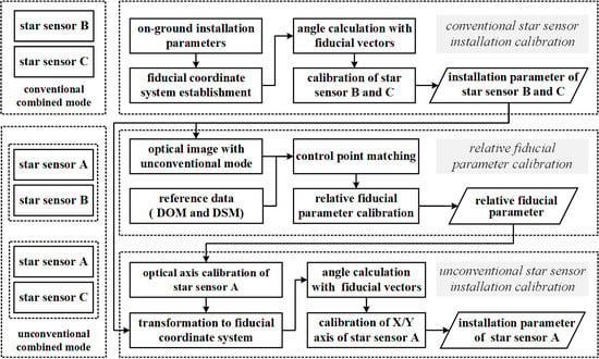
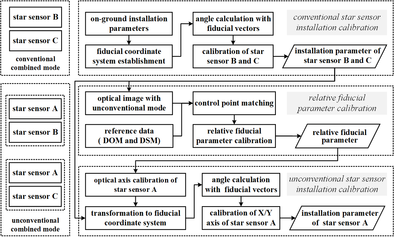
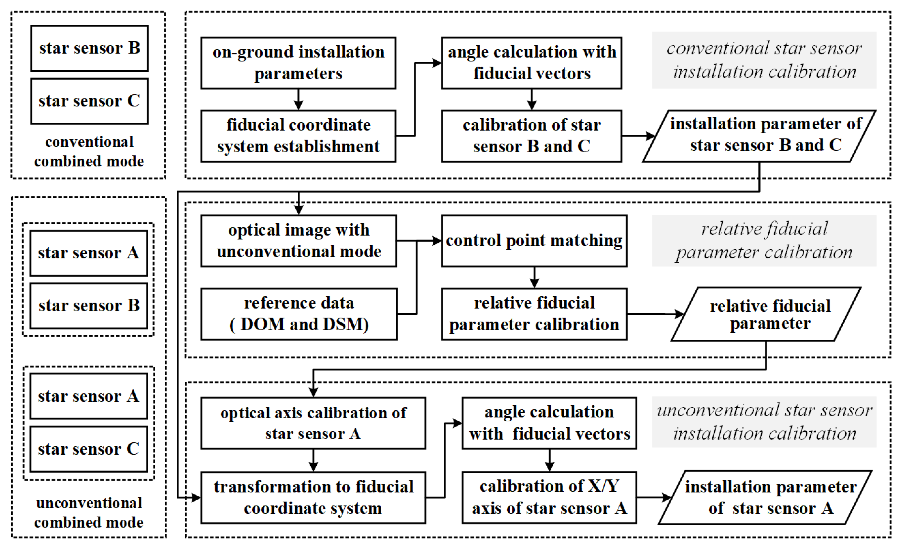
The proposed method for the on-orbit calibration of the installation parameters of a multiple star sensors system based on GCPs is divided into three parts: the installation parameters’ calibration of the conventional star sensor, relative fiducial parameters’ calibration, and installation parameters’ calibration of the unconventional star sensor, as shown in
Figure 2. Star sensors B and C are regarded as the conventional star sensors. Star sensor A is considered the unconventional star sensor. Based on the on-ground installation parameters of the optical axes of star sensors B and C, the fiducial coordinate system is proposed as the calibration coordinate system. The installation parameters of the conventional star sensors are calibrated using the statistical characteristics of the angle between the axis of the star sensor and the three fiducial vectors in the
J2000 celestial coordinate system. By analyzing the relationship between the conventional combined mode and unconventional combined mode, a relative fiducial model is proposed to achieve a transformation from the virtual body coordinate system decided by the unconventional combined mode to the fiducial coordinate system. Using GCPs, the relative fiducial parameters are calculated, and the installation parameter for the optical axis of star sensor A is calibrated. Based on the calibration result for the optical axis, the installation parameters of star sensor A are calibrated, based on the statistical characteristics of the angle in the unified fiducial coordinate system.
2.1. Installation Parameters Calibration of Conventional Star Sensors
2.1.1. Fiducial Coordinate System
On the ground, the satellite body coordinate system is seen as the fiducial coordinate system for installation parameter measurements of a star sensor. The origin of the body coordinate system is located at the centre of the satellite. The
x-axis points to the flight direction of satellite, and the
z-axis points to the observation direction with the ground. The direction of the
y-axis is defined by the right-hand rule. For the star sensor coordinate system, the origin is located at the center of the imaging plane of the light detector. The
z-axis (optical axis) is coincident with the optical axis of the star sensor, and the
x-axis and
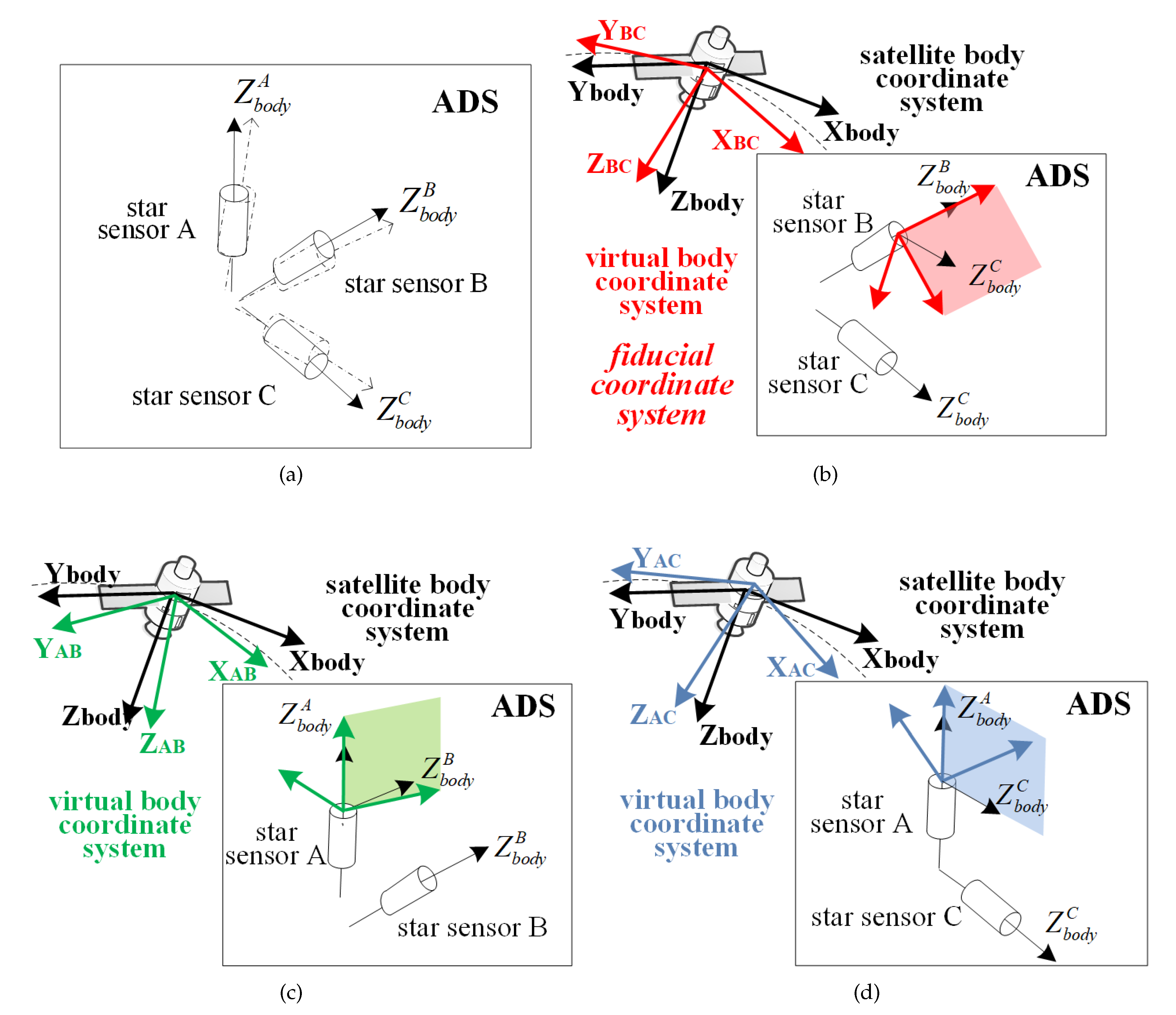
y-axis (horizontal axis) are located on the imaging plane. Using on-ground measurement, the installation parameters of the optical axes of the star sensors A, B, and C in the body coordinate system can be obtained, as shown by the dashed arrows in
Figure 3a. However, owing to the influences of emission vibrations, stress releases of the structure on-orbit, and the space thermal environment, the optical axis installations can be changed, as shown by the solid arrows in
Figure 3a.
Generally, the optical axis of star sensor B is non-parallel with the optical axis of star sensor C. Based on the unit vector of an optical axis in body coordinate system, three orthogonal vectors
can be calculated in the body coordinate system, using the following equation:
where
and
are the installation parameters of the optical axes of star sensor B and star sensor C in the body coordinate system, respectively. Based on
, the position of the satellite body coordinate system can be uniquely determined. When the optical axis vectors of the star sensors are accurate, the positions of the satellite body coordinate system, as determined using the different orthogonal vectors from the different star sensor combination modes, are consistent. If there is an installation error in the optical axis of the star sensors, it will cause the positions of the satellite body coordinate system as determined by the different star sensor combination modes to be inconsistent and will form different virtual body coordinate systems. As shown in
Figure 3b, the virtual body coordinate system formed by star sensor B and star sensor C is expressed by the red coordinate system
. The virtual body coordinate system formed by star sensors A and B is shown in
Figure 3c. The virtual body coordinate system formed by star sensors A and C is shown in
Figure 3d. Owing to the on-orbit installation error, different attitude transform matrices express the orientation of the corresponding virtual body coordinates for different star sensor combination modes in the
J2000 coordinate system, decreasing the accuracy in geometric positioning.
Before installation parameter calibration, a new fiducial coordinate system is proposed to replace the original satellite body coordinate system as the calibration coordinate system. For the satellite only working with two star sensors simultaneously, the virtual body coordinate system is defined by the orthogonal vectors constructed by the optical axes of the conventional star sensors. Therefore, in this study, the fiducial coordinate system for installation parameter calibration is . The orthogonal vectors are named as the fiducial vectors.
2.1.2. Conventional Star Sensor Calibration
According to the definition of the fiducial coordinate system, the on-ground installation parameter of the optical axis of the star sensor B is correct in the fiducial coordinate system. For conventional star sensor calibration, the installation parameters of the horizontal axes of star sensor B and the three axes of star sensor C need to be calibrated.
The measurement data of star sensor B and sensor C in the
J2000 coordinate system can be expressed as the following equation:
In the above,
are the unit vectors of the
x-axis,
y-axis, and
z-axis of star sensor B in the
J2000 coordinate system, respectively.
are the unit vectors of the
x-axis,
y-axis, and
z-axis of star sensor C in the
J2000 coordinate system, respectively.
Based on the unit vector of the optical axis, the fiducial vectors in
J2000 coordinate system
can be calculated using the following equation:
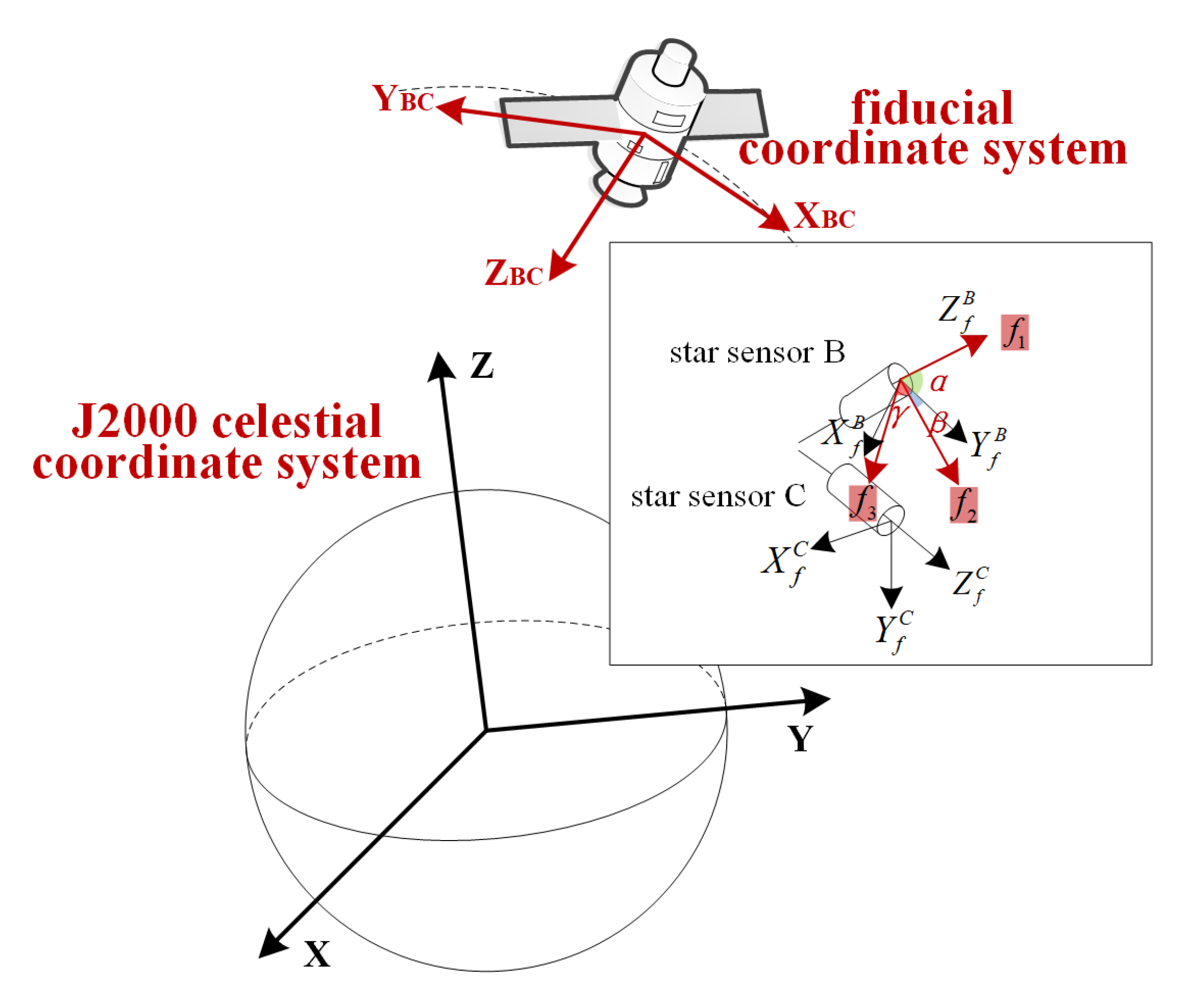
As shown in
Figure 4, the angle between the optical axis of star sensor C and the fiducial vectors in the
J2000 coordinate system can be expressed as in the following equation:
Here,
are the values of the angles between the optical axis of star sensor C and the fiducial vectors
in the
J2000 coordinate system, respectively.
In the fiducial coordinate system, the angle between the optical axis of the star sensor C and the fiducial vectors can be expressed by the following equation:
In this equation,
is the installation parameter of the optical axes of star sensor C in the fiducial coordinate system.
As the angles are equal, they can also be expressed by the following equation:
Let:
The foregoing can be expressed as the following equation:
When the number of measurement data of star sensor B and C is k, the optimal estimation of the angles is the expectation as the following equation:
The installation parameters of the optical axis of the star sensor C by on-orbit calibration can be obtained as:
Similarly, the installation parameters of the horizontal axes of star sensors B and C can be well-calibrated in the fiducial coordinate system.
2.2. Relative Fiducial Parameter Calibration
2.2.1. Relative Fiducial Parameters
In this study, owing to installation errors of star sensor A, there is a systematic angle deviation between the virtual body coordinate system formed by star sensors A and B or star sensors A and C and the fiducial coordinate system. This error is defined as the relative fiducial error. The relative fiducial parameters are used to express the relative fiducial error in the form of Euler angles, as in the following equation:
Here,
are the relative fiducial parameters from the virtual body coordinate system formed by star sensors A and B and the fiducial coordinate system.
are the relative fiducial parameters from the virtual body coordinate system formed by star sensors A and C and the fiducial coordinate system.
2.2.2. Calibration for Relative Fiducial Parameters
As there are only two star sensors working simultaneously, it is necessary to use an optical remote sensing image and the GCPs to calibrate the relative fiducial parameters. By imaging using the conventional combination mode, the geometric positioning model of an optical remote sensing satellite is shown as follows [
20,
21,
22,
23]:
In the above,
are the image coordinates,
are the object coordinates, and
represent the satellite position in the world geodetic system 1984 (WGS84). In that regard,
are the transformation matrices for the
J2000 conventional inertial system to the WGS84 system, the fiducial coordinate system to the
J2000 coordinate system, and the camera coordinate system to the fiducial coordinate system, respectively.
is a scale parameter.
When the satellite observes using an unconventional combination mode (e.g., star sensors A and B), the attitude of the satellite is determined by the installation parameters of the optical axes using the TRIAD algorithm [
24,
25,
26]. To ensure the consistency of the geometric accuracy of remote sensing image in the conventional combined mode, the relative fiducial parameters are adopted into the geometric positioning model, as shown in the following equation:
Then, the calibration model of the relative fiducial parameters can be expressed as in the following equation:
Let:
The calibration model for the relative fiducial parameters can also be expressed as in the following equation:
With the linearization, the error equation can be established as follows:
Here,
is a constant vector, calculated using the equation with the relative fiducial parameters.
is the coefficient matrix of the error equation.
X is the corrected value of the relative fiducial parameter.
is the weight matrix of observations and is set as the unit matrix. i is the index of the GCPs.
According to the error equation, when there are at least two non-collinear GCPs, the relative fiducial parameters can be calculated. To ensure the reliability of the calibration, with the high-precision digital orthophoto maps (DOM) and digital surface model (DSM), many uniformly-distributed and high-accuracy GCPs are automatically selected using a high-precision dense matching method to calculate the relative fiducial parameters.
With the proposed calibration model and the least squares adjustment principle, the iterative solution process for relative fiducial parameter calibration can be implemented.
The calculation of normal equation coefficient matrix is as follows:
The calculation of corrected value of the relative fiducial parameter with the least squares adjustment principle is as follows:
The update of the relative fiducial parameter is represented by:
Here,
j is the index of iteration.
The iterative calculation continues until the corrected value of the relative fiducial parameter is less than the setting threshold.
2.3. Installation Parameters Calibration of Unconventional Star Sensors
According to the relative fiducial parameters, the installation parameters of the optical axis of star sensor A in the fiducial coordinate system can be calibrated, using the following equations:
In the above,
is the installation parameter of the optical axis of star sensor A in the fiducial coordinate system.
is the on-ground installation parameter of the optical axis of star sensor A in the body coordinate system.
Based on the calibration results of the installation parameters of the optical axes of star sensors A and B, three orthogonal fiducial vectors are established. The expression of the fiducial vectors in the fiducial coordinate system
can be calculated as shown in Equation (
32). The expression of the fiducial vectors in the
J2000 coordinate system
can be calculated as shown in Equation (
33):
In that regard,
is the optical axis of star sensor A in the
J2000 coordinate system.
As the optical axis of star sensor A has been calibrated, the virtual body coordinate system determined by is coincident with the fiducial coordinate system. According to the statistical characteristics of the angle between the horizontal axes of star sensor A and the fiducial vectors in the J2000 coordination system, the installation parameters of the horizontal axes of star sensor A can be calibrated.
2.4. Calibration Accuracy Evaluation Index
Three indexes are adopted for evaluating the calibration accuracy of the proposed method. They are the relative installation error, attitude determination consistency, and geometric accuracy improvement.
In the approach for installation parameter calibration, the original satellite body coordinate system is replaced by the fiducial coordinate system. The absolute installation parameters in the fiducial coordinate system are different from those in the original satellite body coordinate system. However, the relative installation relationship between star sensors is constant in any coordinate system. Therefore, the relative installation error is applied here to evaluate the calibration accuracy. In this study, star sensor B is used as the fiducial star sensor. Thus, the relative installation parameter from star sensor A to star sensor B and the relative installation parameter from star sensor C to star sensor B are adopted here to verify the accuracy of calibration. The relative installation error from star sensor C to star sensor B can be expressed by the following equation:
In the above,
are the true on-orbit installation parameters of star sensor B and star sensor C in the original satellite body coordinate system, respectively.
is the true value of the relative installation matrix.
are the true values of the relative installation parameters. In the fiducial coordinate system in this study,
are the calibrated installation parameters of star sensor B, calibrated installation parameters of star sensor C, and the calibrated relative installation matrix, respectively.
are the calibration values of the relative installation parameters in the fiducial coordinate system. The relative installation error
between the calibrated relative installation parameters and the true value is adopted to evaluate the calibration accuracy.
When the installation parameters of the star sensor are well-calibrated, the results from the attitude determinations by the different star sensor combination modes are consistent. Therefore, the attitude determination consistency of the different star sensor combination modes is applied here to evaluate the calibration accuracy. The results of the attitude determinations with star sensors B and C are adopted here as the reference results for testing the attitude determination consistency with other attitude determination modes:
Here,
are the attitude parameters determined by star sensors B and C.
are the attitude parameters determined by star sensors A and B.
are the attitude parameters determined by star sensors A and C.
are indexes for the attitude determination consistency.
For an on-orbit remote sensing satellite working with only two star sensors, it is impossible to obtain the true value of the installation parameter in the satellite body coordinate system and the measurement data of the three star sensors simultaneously. The improvement in the geometric accuracy of the remote sensing images measured using the unconventional combined modes before and after calibration indicates the effect of the installation parameter calibration for the star sensor. Thus, the geometric accuracy improvement is also adopted to verify the accuracy and reliability of the proposed method for installation parameter calibration.
3. Experimental Results
3.1. Study Area and Data Source
To verify the accuracy and reliability of the proposed approach for installation parameter calibration of a multiple star sensors system, simulation data were utilized in the experiment. The simulation data included a simulation of the measurement data of the star sensor and a simulation of the high-resolution optical remote sensing image. In the measurement data simulation, the measurement accuracy of the optical axis of the three star sensors was
. The measurement accuracy of the horizontal axis of the three star sensors was
. The frequency was set to 4 Hz, and the number of data was 61. The difference between the on-orbit installation parameters and the on-ground parameters measurements is 100″. Detailed information regarding the on-ground and on-orbit installation parameters of the star sensors is listed in
Table 1. Based on the simulation attitude of the satellite in the
J2000 coordinate system and the on-orbit installation parameters, the true attitude data of the star sensors was calculated via a matrix operation. The measurement data of the star sensors was calculated by adding the measurement error of the axis to the true attitude. Star sensors B and C were adopted as the conventional star sensors, and star sensor A was seen as the unconventional star sensor. The on-ground installation parameters were used as the initial parameters for calibration.
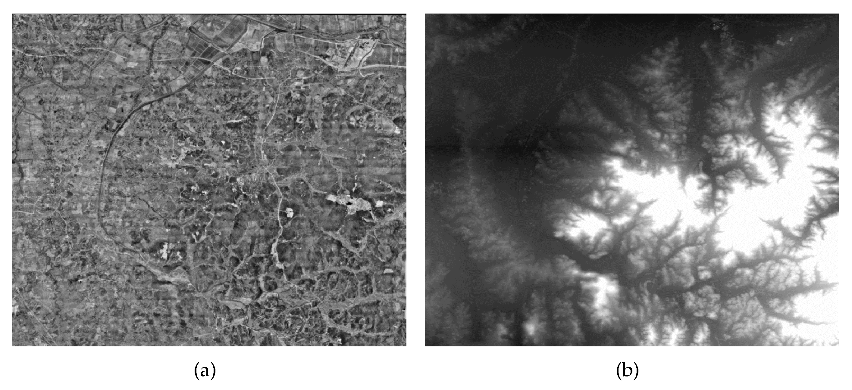
Table 2 lists detailed information regarding the parameters of the image simulation. The satellite orbit altitude was 500 km, and the resolution of the high-resolution optical remote sensing image was set as 0.5 m. A DOM with resolution of 0.1 m and a DSM with resolution of 5 m covering the Lujiang area in China were used as reference data for the image simulation, respectively, as shown in
Figure 5. With the orbit data, attitude data, camera parameters, and reference data, the high-resolution optical remote sensing image could be simulated by the rigorous geometric positioning model, for application to the relative fiducial parameter calibration.
3.2. Calibration for Multiple Star Sensors System
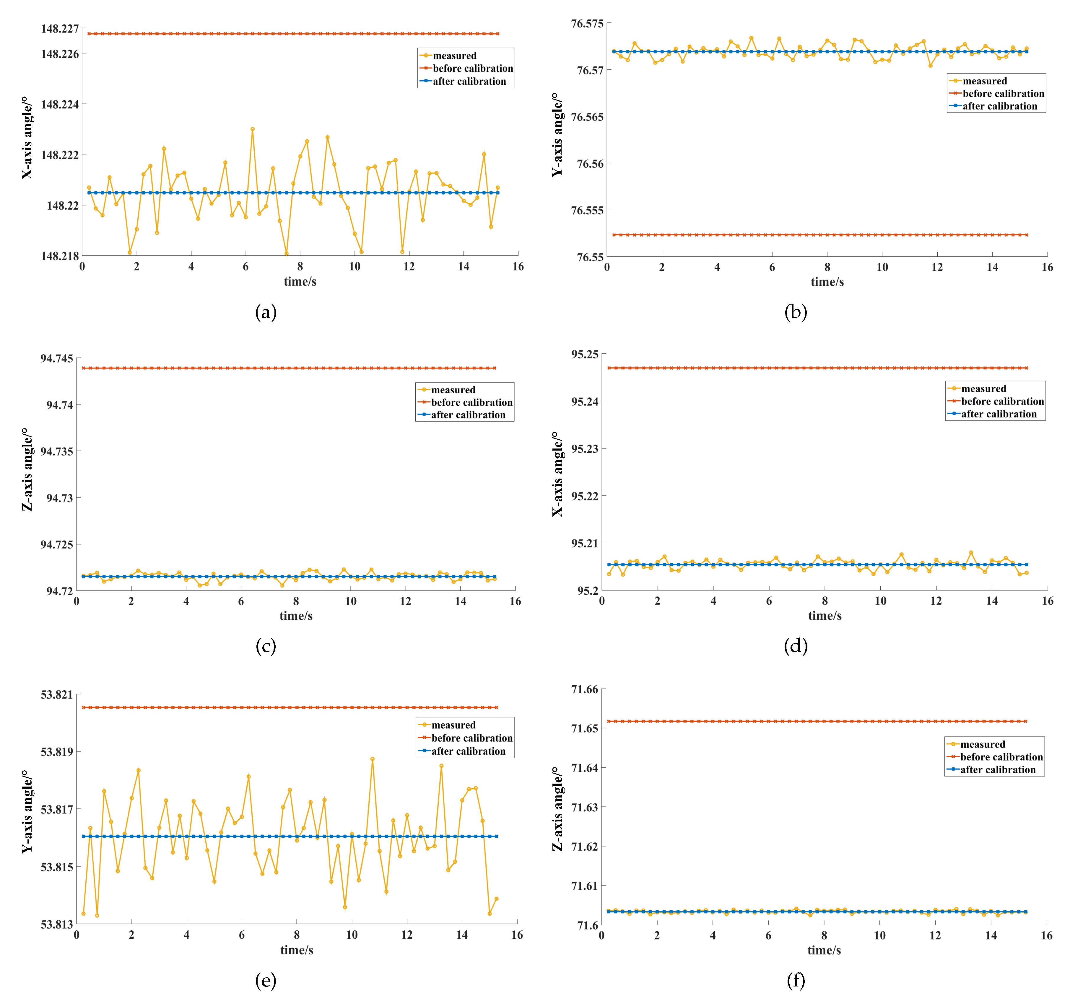
With regard to the installation parameters calibration for the conventional star sensors, the angles of the coordinate axes between star sensor B and star sensor C are shown in
Figure 6, and the errors of these angles (to the true values) are listed in
Table 3. For the measurement data in the
J2000 system, the
x-axis angle of star sensor B and C is from 148.218° to 148.223°, as shown in
Figure 6a. The
y-axis angle is from 76.570° to 76.573°, as shown in
Figure 6b. The
z-axis angle is from 94.721° to 94.722°, as shown in
Figure 6c. As the measurement accuracy of the horizontal axis is lower than that of the optical axis, the distribution range of the
x-axis angle and
y-axis angle of star sensors B and C is larger than that of the
z-axis angle, further influencing the differences in calibration accuracy among the three axes. As listed in
Table 3, the errors of the
x-axis angle,
y-axis angle, and
z-axis angle are −1.524″, −0.669″, and −0.159″, respectively. The calibration accuracy of the optical axis is higher than that of the horizontal axis. This is because the calibration accuracy of the
z-axis is only influenced by the measurement accuracy of the optical axis, whereas the calibration accuracies of the
x-axis and
y-axis are subjected to the measurement accuracies of both the optical axis and horizontal axis in the proposed method.
The relative installation error between star sensors B and C is calculated as listed in
Table 4. Before calibration, the relative installation errors of the yaw, roll, and pitch angles are 230.676″, 20.950″, and 208.190″, respectively. After calibration, the relative installation errors are a yaw of −1.349″, roll of 0.370″, and pitch of 0.558″. As restricted by the measurement noise of the star sensor, there is a certain deviation of the statistical angle with the fiducial vectors between the measurement data and the true value, which influences the calibration accuracy. The relative installation error of the yaw angle is larger than that of the roll or pitch angles. According to the relationship between the rotation angle and coordinate axis, the yaw angle of a relative installation parameter is only related to the calibration accuracy of the horizontal axis, whereas the roll and pitch angles of a relative installation parameter are related to the calibration accuracy of both the horizontal and optical axes. The calibration accuracy of the optical axis is not affected by the measurement accuracy of the horizontal axis and is higher than the calibration accuracy of the horizontal axis.
Using the calibration model and GCPs, the relative fiducial parameters from the virtual body coordinate system formed by star sensors A and B to the fiducial coordinate system can be calculated, as listed in
Table 5. The true value of a relative installation parameter is calculated by a matrix operation with the true value of the on-orbit installation parameters. The calibration accuracy of the relative fiducial parameters includes the errors in the yaw, roll, and pitch angles of the relative fiducial parameters, which are −0.012″, −0.010″, and −0.054″, respectively. As the attitude determination is only related to the optical axis, the calibration accuracy of the relative fiducial parameters is not influenced by the measurement accuracy of the horizontal axis, which is restricted by the measurement accuracy of the optical axis, geometric accuracy of the reference image, and matching accuracy.
For the unconventional combined mode with star sensors A and C, the calibration of the relative fiducial parameters is tested for comparison with the different combined modes. The errors in the yaw, roll, and pitch angles of the relative fiducial parameters are −0.100″, 0.069″, and 0.025″, respectively, i.e., similar to the calibration accuracy of the star sensors A and B combined mode. In the proposed method, the installation parameter of the optical axis of star sensor B is the on-ground parameter, and there is no need for the extra calibration. The installation parameter of the optical axis of star sensor C is calibrated. The approximate calibration accuracies of the different unconventional combined modes demonstrate that the optical axis of star sensor C is calibrated well using the proposed method.
Based on the installation parameter calibration of star sensor A, the angles of the coordinate axes between star sensor A and star sensor B are shown in
Figure 6, and the errors of these angles to the true values are listed in
Table 3. As the measurement accuracy of the horizontal axis is lower than that of the optical axis, the distribution range of the angles between the horizontal axes of star sensors A and B in
Figure 6d,e is larger than that of the optical axis in
Figure 6f. As listed in
Table 3, the errors of the angles of the
x-axis,
y-axis, and
z-axis are −1.671″, −1.922″, and −0.047″, respectively, similar to the characteristics of the angle of star sensors B and C. The calibration accuracy of the optical axis of star sensor A is only related to the calibration accuracy of the relative installation parameter, which is influenced by the measurement accuracy of the optical axis. The calibration accuracy of the
x-axis or
y-axis is subjected to the measurement accuracy of the optical axis and the horizontal axis under the proposed approach.
Table 6 lists the relative installation errors of star sensors A and B. Before calibration, the relative installation errors of the yaw, roll, and pitch angle were 167.027″, 272.050″, and 139.558″, respectively. After calibration, the relative installation errors of the yaw, roll, and pitch angles were −2.208″, 0.698″, and −0.145″, respectively, which is similar to the results from conventional star sensor calibration. The yaw angle of the relative installation error reflects the calibration accuracy of the horizontal axis, whereas the roll and pitch angles of the relative installation error reflect the calibration accuracy of the horizontal axis and optical axis. The installation parameter of optical axis of an unconventional star sensor is not influenced by the lower measurement accuracy of the horizontal axis.
3.3. Attitude Determination Consistency
The results of the attitude determination consistencies for the different combined modes are listed in
Table 7. The minimum error (MIN), maximum error (MAX), mean error (MEAN), and root mean squared error (RMS) of the Euler angles are calculated to evaluate the attitude determination accuracy.
Before calibration, for the unconventional combined mode with star sensors A and B, the yaw MEAN, roll MEAN, and pitch MEAN were −62.769″, −74.766″, and −185.459″, respectively. The yaw RMS, roll RMS, and pitch RMS were 62.782″, 74.772″, and 185.463″, respectively. For the unconventional combined mode with star sensors A and C, the yaw MEAN, roll MEAN, and pitch MEAN were −118.759″, −294.763″, and −16.900″, respectively. The yaw RMS, roll RMS, and pitch RMS were 118.780″, 294.772″, and 16.914″, respectively. Using the proposed approach for on-orbit calibration, the yaw MEAN, roll MEAN, and pitch MEAN of the attitude determination consistency with star sensors A and B were 0.114″, −0.033″, and 0.052″, respectively. The yaw MEAN, roll MEAN, and pitch MEAN of the attitude determination consistency with star sensor A and C were 0.083″, 0.075″, and −0.005″, respectively. The MEAN of the unconventional combined modes to the conventional combined mode is close to 0. This demonstrates that systematic error is eliminated by the proposed method. The yaw RMS, roll RMS, and pitch RMS of the attitude determination consistency with star sensors A and B were 1.185″, 0.551″, and 1.066″, respectively. The attitude determination consistency with star sensors A and C is also close to 1″, with a yaw RMS of 1.115″, roll RMS of 2.281″, and pitch RMS of 0.608″, which approximately reflects the measurement accuracy of the optical axis . The attitude determination consistency of the different combined modes is influenced by the measurement noise and does not include the system error, illustrating that the installation parameters of the three star sensors are calibrated well by the proposed method.
3.4. Geometric Accuracy Improvement
The geometric accuracy improvements for a remote sensing image from the different combined modes are listed in
Table 8. For conventional combined mode with star sensors B and C, the plane accuracy was 0.043 pixels before calibration, which was used as the attitude data for image simulation. After calibration, the plane accuracy was 0.148 pixels. Based on the principles of the TRIAD algorithm, the attitude result with the on-ground installation parameter is similar to that as determined by the calibration installation parameter, causing the similar geometric accuracy of the remote sensing images, and demonstrating that the optical axis of star sensor C is calibrated well. From the installation calibration of star sensor A, the geometric accuracy of the remote sensing image as simulated by the unconventional combined mode with star sensors A and B improved from 439.317 pixels to 1.890 pixels. The geometric accuracy simulated by the unconventional combined mode with star sensors A and C improved from 318.263 pixels to 3.082 pixels. The geometric accuracy of the unconventional combined modes evidently improved, demonstrating the unified calibration of the installation error of star sensor A in the fiducial coordinate system. The difference in geometric accuracy between the conventional star sensor mode and the unconventional star sensor mode is approximately 3 pixels, and is caused by the measurement noise of the optical axis.
3.5. Experiment with On-Orbit Satellite
For an on-orbit satellite that works with only two star sensors simultaneously, three panchromatic images are used as test images for evaluating the geometric accuracy improvement before and after installation calibration.
Table 9 lists the geometric accuracy before and after installation calibration with different star sensor combinations, as tested using the reference DOM and digital elevation model (DEM). The reference DOM was obtained from aerial images and WorldView3 satellite images. The second version of the ASTER global digital elevation model (GDEM2) was used as the reference DEM, with an average vertical accuracy of −0.20 m, and an accuracy of 17 m at the 95% confidence level [
27].
For the conventional combined mode with star sensors B and C, the plane error was 15.207 pixels before calibration. Using the proposed method, the plane error was 15.156 pixels, which is similar to the geometric accuracy before calibration. In that regard, the construction of the fiducial coordinate system in the proposed approach is based on the on-ground installation parameters of star sensors B and C. Thus, , , and are coplanar in the fiducial coordinate system. Based on the principle of the TRIAD algorithm, the results of the attitude determination before and after calibration express the orientation of the fiducial coordinate system in the J2000 system, causing the constant geometric accuracy.
Before calibrating the installation parameters of star sensor A, for the unconventional combined modes, the cross-track errors with star sensors A and B mode and star sensors A and C mode were 48.817 pixels and 350.708 pixels, respectively. The along-track errors were −86.385 pixels and −124.669 pixels, respectively. Affected by the installation errors of star sensor A, the geometric accuracies of three panchromatic images are inconsistent. After calibrating the installation parameters of star sensor A, the geometric errors with star sensor A and B mode and star sensor A and C mode were 8.558 pixels and 14.771 pixels, respectively. The geometric accuracy of the unconventional combined modes significantly improved. Therefore, the installation parameter of the unconventional star sensor A was calibrated well by the proposed method. According to the experimental results of the real data of on-orbit satellite, it demonstrates that the proposed approach makes the results of attitude determinations from different star sensor combination modes consistent and improves the geometric accuracy of the remote sensing images.
5. Conclusions
For a star sensor, owing to the vibrations and thermal shocks that arise during launch and the orbit penetration process, there are errors between the on-orbit installation parameters and on-ground measurement parameters, causing inconsistencies in attitude determinations from different combination modes, and seriously affecting the geometric accuracy of high-resolution optical remote sensing images. This study is dedicated to solving the on-orbit calibration of installation parameters of a multiple star sensors system, which is based on the statistical characteristics of the angles and GCPs. With the statistical characteristics of the angle in the J2000 celestial coordinate system, the installation parameters of the conventional star sensors are calibrated in the fiducial coordinate system. Then, the relative fiducial matrix is modeled to achieve the transformation from virtual body coordinate system to the fiducial coordinate system and is calculated using the GCPs. The installation parameters of the unconventional star sensor are calibrated using the relative fiducial matrix and the statistical characteristics of the angle with the fiducial vector.
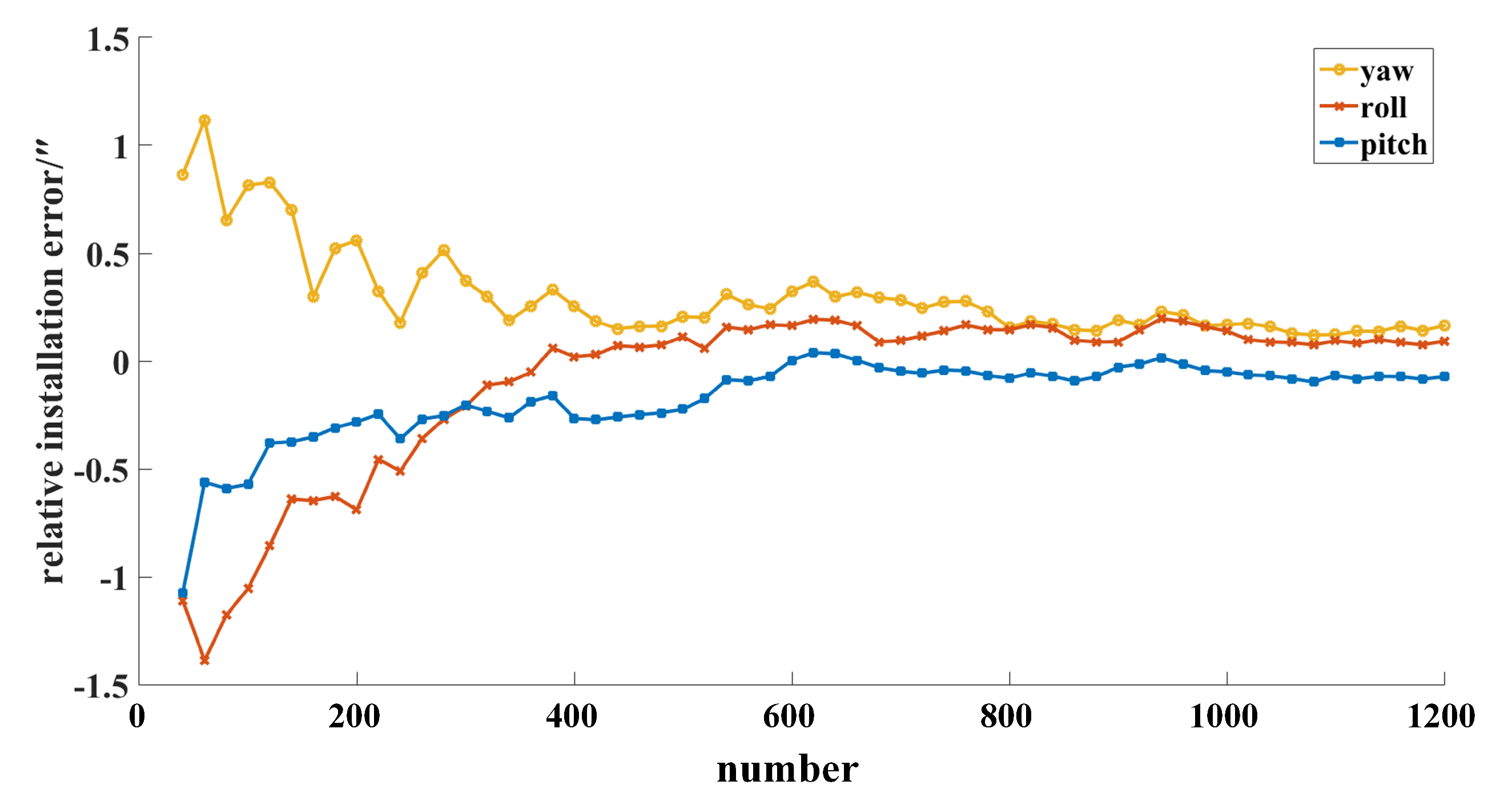
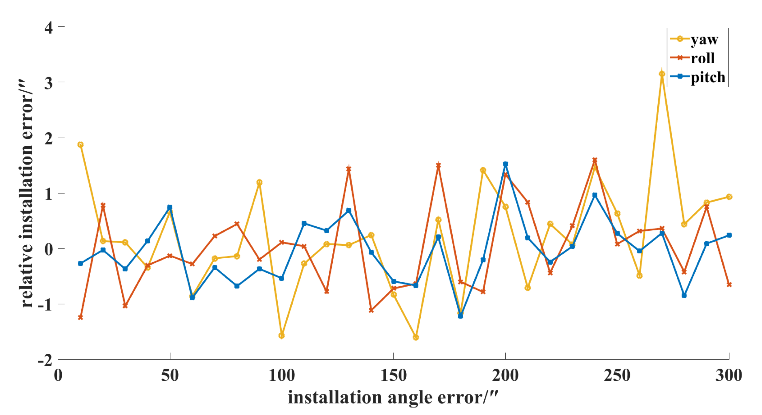
The proposed method is tested with simulated data and on-orbit measurement data. The results demonstrate that the proposed method can calibrate the optical axis of a star sensor without the measurement noise of the horizontal axis. With the increase of the number of measurement data, the calibration accuracy is gradually improved. A star sensor with a large installation angle error can be well-calibrated by the proposed approach. The results of attitude determinations from different star sensor combination modes are consistent, and the geometric accuracy of the remote sensing images is significantly improved.


