
Efficient Multipath Clutter Cancellation for UAV Monitoring Using DAB Satellite-Based PBR


1
School of Information and Electronics, Beijing Institute of Technology, Beijing 100081, China
2
Key Laboratory of Electronic and Information Technology in Satellite Navigation, Ministry of Education, Beijing 100081, China
3
State Radio Monitoring Center, Beijing 100037, China
4
Advanced Technology Research Institute, Beijing Institute of Technology, Jinan 250300, China
*
Author to whom correspondence should be addressed.
Remote Sens. 2021, 13(17), 3429; https://0-doi-org.brum.beds.ac.uk/10.3390/rs13173429
Submission received: 4 July 2021
/
Revised: 12 August 2021
/
Accepted: 25 August 2021
/
Published: 29 August 2021
Abstract
:The increasing accessibility of unmanned aerial vehicles (UAVs) drives the demand for reliable, easy-to-deploy surveillance systems to consolidate public security. This paper employs passive bistatic radar (PBR) based on a digital audio broadcast (DAB) satellite for UAV monitoring in applications with power density limitations on electromagnetic radiation. An advanced version of the extensive cancellation algorithm (ECA) based on data segmentation and coefficients filtering is designed to improve the efficiency of multipath clutter suppression while retaining robustness, for which the effectiveness is verified by theoretical derivation and simulation. The detectability of small UAVs with DAB satellite-based PBR is validated with experimental results, with which the influence of target altitude and bistatic geometry are also analyzed.
1. Introduction
With the progress of technology and cost reduction, unmanned aerial vehicles (UAVs) have been widely used in the military, industrial, and civil fields, for which the increasing accessibility poses unprecedented threats to infrastructure and public safety. Therefore, more and more attention has been paid to the corresponding monitoring technologies as detection is required before proper disposal. Compared with other surveillance means such as laser and photoelectricity, radar-based systems have an insensitivity to environmental changes and strong all-day, all-weather applicability and, thus, are used in many applications [1,2,3,4] in which the feasibility for UAV detection has been shown in [5,6,7]. Unfortunately, the high radiation power from active radar aggravates the complexity of the surrounding electromagnetic environment, and its use might be limited to avoid other severe safety accidents in some sensitive areas, such as oil depots and granaries.
For such scenarios, passive bistatic radar (PBR) based on an illuminator of opportunity becomes an attractive solution because of the feasibility of non-cooperative surveillance while staying radio-silent. Unlike conventional monostatic systems, passive radar utilizes the scattering of existing radio signals from targets to perform surveillance, which is accumulated according to the reference signal obtained with an additional receiving channel pointing towards the illuminator. Thus, target detection can be completed with less power consumption as long as a suitable radio emitter covers the target area, and the system’s impact on the surrounding electromagnetic environment can be ignored.
PBR usually uses a reference signal with stable radiation power, such as broadcast and cellular communication, to realize habitus monitoring, the capability of which has been shown to have many different terrestrial illuminators [8,9,10,11,12,13,14]. In practical usage, due to similar reasons as for active radar, the power density of electromagnetic radiation is limited in many cases [15,16], and thus, the system capability might be affected by the availability of appropriate illuminators.
Spaceborne illuminators can be applied to more scenarios because of the broader coverage area provided by their giant footprints and evenly distributed power density. In recent works, [17,18] used global navigation satellite system (GNSS) signals to realize UAV detection. Due to the low ground power density, a substantial receiving antenna is needed to intensify the echo from weak targets, dramatically increasing system costs. As an alternative, digital satellite TV systems (DVB-S) located in synchronous orbit are used in [19,20,21] to enlarge the detection range and to analyze the micro-Doppler signature of targets. Although with a higher power density and negligible emitter motion, the Ku band signals, more precisely from 10.7 GHz to 12.75 GHz, exacerbate the environmental attenuation and radar cross-sectional (RCS) fluctuation, limiting the gain from the coherent processing interval (CPI) increment. Therefore, the feasibility of UAV monitoring using spaceborne illuminators with lower radiation frequency is worthwhile to explore further.
Usually, target echoes are much weaker than direct wave and multipath interference, which inevitably leads to a massive mask effect in the two-dimensional cross-correlation function (2D-CCF). The influence on the detection performance needs to be prevented by the cancellation of multipath clutter, and many suppression algorithms have been proposed in previous works [22,23,24,25,26], some of which, such as [27,28,29,30], are designed in the sub-carrier domain for PBR based on orthogonal frequency division multiplex (OFDM) broadcasting and thus are not applicable to emitters such as DAB satellite.
Among the algorithms without specific modulation restriction, the extensive cancellation algorithm (ECA) derived from the least-squares (LS) estimation [31,32] is chosen in this work for its excellent convergence and suppression performance. Compared with the algorithms based on adaptive filters such as [26,33], the effect of ECA is determined by more intuitive factors such as the clutter extension range or Doppler resolution rather than the step size, which enhances the robustness of parameter selection. However, as mentioned in [23,26], the high computational cost of ECA brings a massive bottleneck to the real-time system.
Many efforts have been made to break the hindrance: the batch version (ECA-B) [31] reduces the processing delay via signal segmentation. However, the ineluctable notch broadening limits the maximum batch number, and the periodic modulation of slow targets restricts its usage. Although these limitations can be overcome via the sliding process, which was introduced by sliding ECA (ECA-S) [34], the computational burden is more severe as the total Flops increase sharply with the batch number. ECA-expectation (ECA-E) and its simplified version (ECA-ES) [35] were developed for better real-time performance via more radical segmentation, making batch-level parallel computing implementable. However, as mentioned later, the constant weight limits the notch width formed via ECA-E (S), and the moving clutters need to be rejected by other algorithms, such as ECA-B.
In this paper, PBR based on a digital audio broadcast (DAB) satellite is selected to detect UAVs in which the illuminator, which is also located at synchronous orbit, works at a frequency band close to GNSS while having a much higher ground power density. An advanced version of ECA is derived based on the orthogonality between clutter subspaces of different Doppler frequencies to reduce the processing overhead and to improve the detectability of low-speed targets. The algorithm first segments the sampled data thoroughly, and each batch’s clutter coefficients are then estimated. After being smoothed with a low-pass filter, these coefficients regenerate the clutter component to perform cancellation. Theoretical analysis and numerical simulation demonstrate the advantage in slow target retention. Additionally, the efficiency improvement and memory usage reduction, which benefit from the compatibility with precompression, are verified for the close-range monitoring. Three groups of experimental data are obtained to validate the detectability of small UAVs, and the influence from target altitude and bistatic geometry is also discussed.
The rest of this paper is organized as follows. The signal model of PBR based on a DAB satellite and the algorithm derivation are given in Section 2 and Section 3. The computational cost and cancellation capability are evaluated theoretically and compared with existing ECA versions in Section 4. In Section 5 and Section 6, the proposed algorithms’ effectiveness is verified by simulation and experimental data, respectively. A further discussion about the experiments is presented in Section 7. Finally, Section 8 concludes the paper with some critical remarks.
2. Signal Model
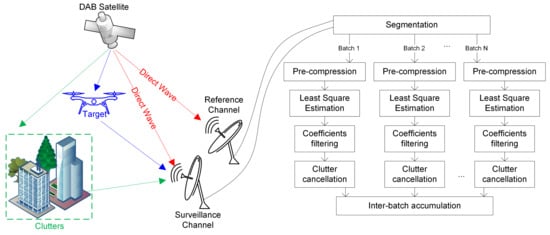
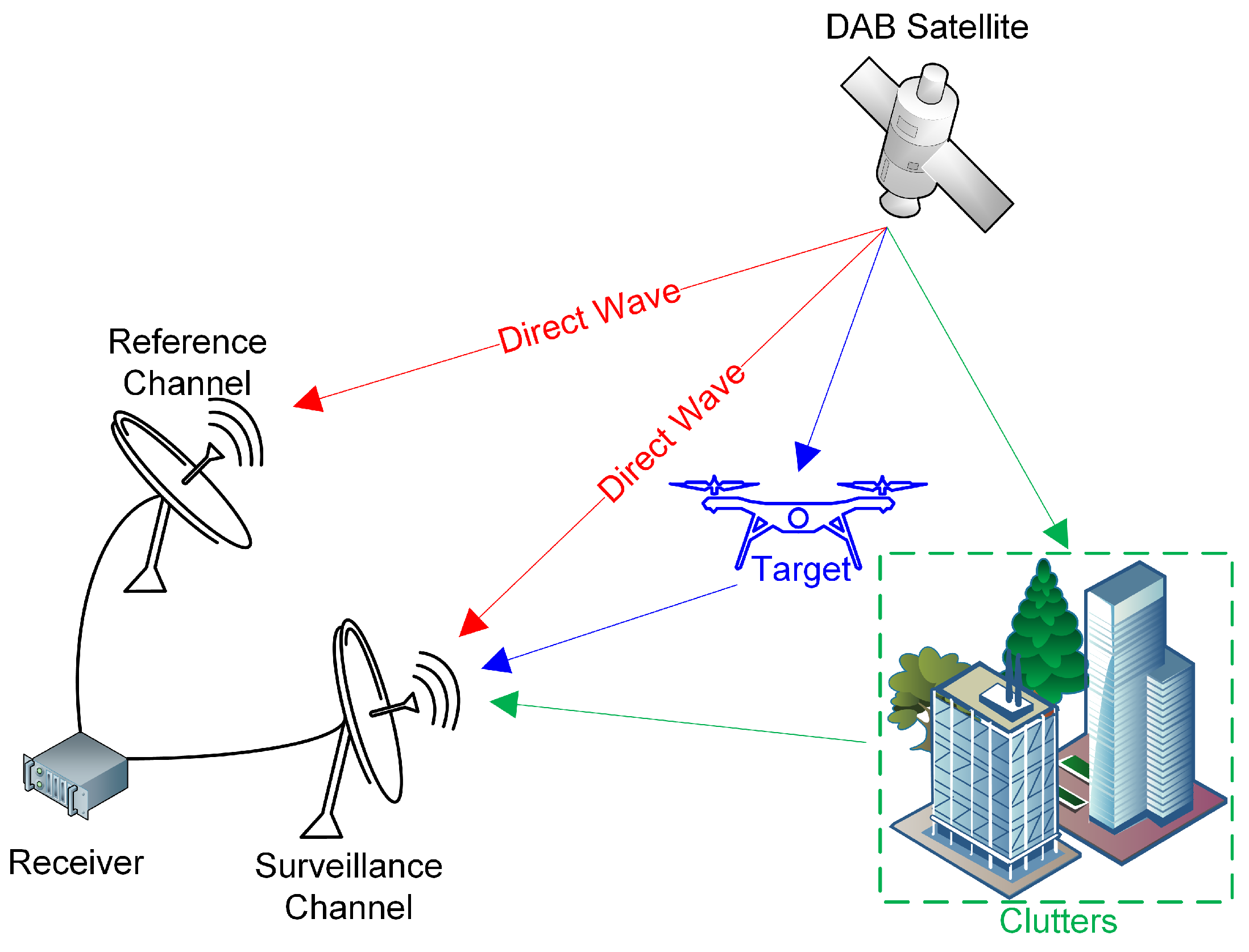
As shown in Figure 1, a typical PBR system based on DAB satellite contains a reference channel and a surveillance channel. The former’s antenna points towards the illuminator to record the pure direct signal. Due to the high signal-to-noise ratio (SNR) from the antenna gain and the reconstruction technology, both the thermal noise and the multipath distributions can be ignored during signal processing [25]. Thus, the reference signal can be expressed as
where represents the complex amplitude and is the normalized direct wave.
On the other hand, the surveillance beam covers the target area, and its recorded signal comprises the direct wave, clutter, the target echo, and receiver noise, which can be modeled as
where , , and represent the amplitude, relative bistatic delay, and Doppler frequency of the ith clutter while , , and denote the same parameters as for the ith target. and are the number of clutters and targets, respectively. indicates the receiver noise. The direct wave is regarded as a stationary clutter at the origin in the formula above without losing generality.
For reliable target detection, the 2D-CCF of the two signals above is calculated to achieve coherent integration, for which the expression can be described as follows:
where denotes a complex conjugate. and are the relative bistatic delay and Doppler frequency of the hypothesized target. T and represent the CPI and the beginning of accumulation, respectively. The result depicted in a range-Doppler map could be processed with a constant false-alarm rate (CFAR) detector.
Unfortunately, most of the targets’ echoes is masked by the clutter component after accumulation because of the continuous illumination and the targets’ weak scattering, which must be resolved prior to the detection stage.
3. Suppression Algorithm
An advanced ECA version is proposed to realize efficient and flexible multipath clutter suppression in the focused scenario. Let denote the sampling frequency of the PBR system; the matrix form of (2) after discrete sampling becomes
where is a vector containing the surveillance signal. and represent the clutter base and target base, for which the column vectors are built with replicas of the reference signal with different delays and Doppler frequencies. and are the corresponding coefficient vectors. denotes the noise vector.
To achieve effective clutter suppression, the standard ECA evaluates the cancellation weights by solving the following LS problem:
with which the restored clutter component can be obtained by and the signal after suppression turns into .
When the base matrices and are orthogonal to each other, it can be proven that the clutter is perfectly canceled, and only consists of the target echo and the noise within the orthogonal space of , the expression of which is as follows:
In order to reduce the matrix dimension, the extended clutter base and estimated coefficient vector are divided according to Doppler frequency, i.e.,
where the subscripts denote the Doppler of each block. Without losing generality, the size of each sub-clutter base, or , is assumed to be , for which the column vectors correspond to the kth range bin in order. When is an integer for all m, could be approximated with a block diagonal matrix. Thus, can be estimated separately:
Similar to [35], the surveillance vector and the sub-clutter base are partitioned into B batches along the column, i.e.,
and the decomposed form of (8) is given by
where represents the solution of each decomposed problem, for which the expression is
The above derivation is only tenable when is non-singular for all . Otherwise, the matrix inversion in (11) does not exist. When the oversampling rate is moderately low, such a premise is well guaranteed because contains only the components with the same Doppler frequency, which prevents the rank reduction caused by the decreasing Doppler resolution. Apart from that, with a stationary reference signal, , and can be approximated by their expectations that differ only in amplitude. Hence, the matrix calculation in (10) can be substituted with a scalar weighting for simplicity at the cost of negligible accuracy loss, of which the expression is as follows:
where and ⊙ represent the norm and the Hadamard product, respectively. indicates the vector of a reference signal modulated by the clutter Doppler phase, of which the column partitions are denoted with subscript b similar to that in (10). Due to its constant modulus, can be ignored during the calculation.
When the reference channel has stable received power and (8) is segmented evenly, the weighting coefficients and (12) can be further simplified as follows:
The above derivation extends the evaluation stage in ECA-E (S) from stationary clutters to moving ones based on the orthogonality between different sub-clutter bases, with which the optimal output is achievable by independent cancellation of different Doppler frequencies. However, the processing faces the dimension inflation caused by Doppler extension, as has to be calculated separately for different . Further approximations are needed to reduce this computational burden.
Notice that the decreasing Doppler resolution drastically enhances the correlation between different within the same batch. When , the following expressions can be taken into (11)
and becomes
Thus, only the zero-Doppler estimations need to be solved at each batch, and the coefficients of moving clutters can be obtained by
With (16), the redundant calculation in the evaluation stage is well eliminated. The same approximation can be applied to the cancellation stage as well, where the following vector is reconstructed to achieve a suppression factor of at specific Doppler frequencies:
The concatenated vector of (17), , can be regarded as a substitution of with a stepped Doppler phase instead of a continuous one. Since , , and have similar outputs after 2D-CCF, its impact on detection is negligible. In fact, can be viewed as a low rank approximation of the corresponding column partition of , and (17) is the result of projection.
Considering that is an N-dimensional Fourier basis, (17) can be reformulated with a circular filter:
where is the output filtered by the following weights:
According to the former analysis, an ECA version based on batch segmentation and circular filter is derived. As discussed in [34], reducing the sampling length decreases the Doppler resolution, bringing about a higher correlation between the low-Doppler clutter bases and the zero-Doppler one. As a result, each batch’s evaluation contains more nonzero-frequency components, some of which are eliminated by the proposed algorithm, named ECA-Circular Filter (ECA-CF), to control the notch width and to retain the target’s energy. Unlike ECA-B, ECA-CF tends to segment the data thoroughly to enlarge the Doppler tolerance range, for which the suppression area is mainly determined by the filter weights instead of the batches’ number. ECA-ES in [35] can be regarded as a particular case of ECA-CF with a constant filter weight of , of which the passband determines that ECA-ES cannot be applied to situations requiring Doppler extension. In contrast, ECA-CF makes clutter cancellation more flexible as the filter weights in (18) can be adjusted separately for different range bins if varying rejection ranges in the Doppler domain are required in practical processing. Although the nonconstant filter weights increase a certain amount of calculation burden, it can be neglected compared with coefficients evaluation as the cost of matrix factorization is much higher.
The above derivation is based on the hypothesis that the extended clutter base only contains the components satisfying . The discontinuity of circular filtering limits the suppression performance of clutters with non-orthogonal frequencies. The filter in (18) can be replaced with a linear one to avoid discontinuity and to ameliorate the above problem. Such a process, called ECA-Linear Filter (ECA-LF), can be regarded as a sliding version of ECA-CF with a step size of 1. Unlike ECA-S towards ECA-B, ECA-LF has an equal computational cost to ECA-CF within the same integration time, as the LS estimations can be reused. However, the unavoidable group delay brought by linear filtering deteriorates ECA-LF’s real-time performance, which can be alleviated to some extent by asymmetric filter weights [36].
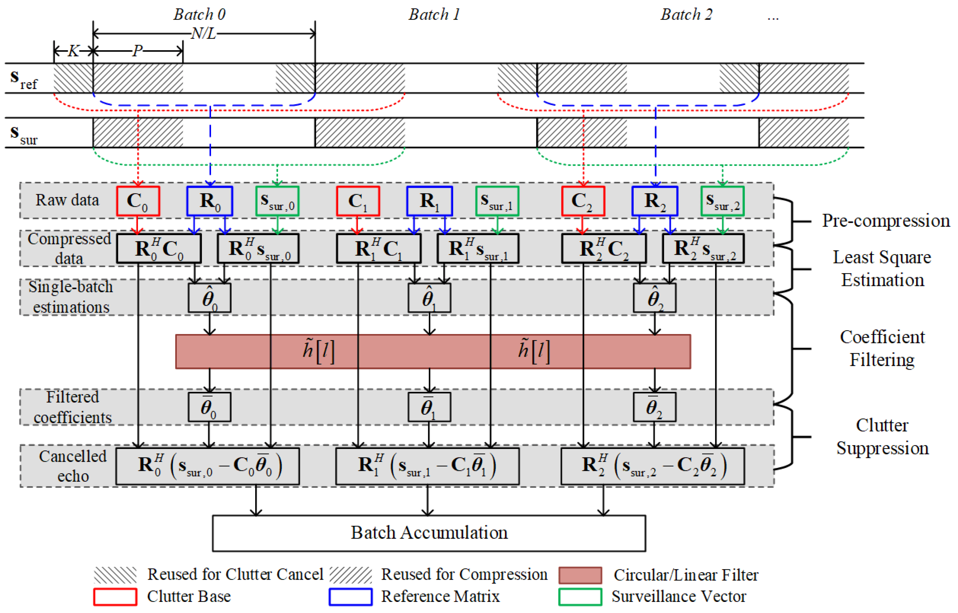
The 2D-CCF is usually calculated using batched 1D-CCF and inter-batch accumulation for efficiency, which resembles the pulse compression and moving target detection (MTD) in traditional pulse radar signal processing. Since the clutter base utilized in ECA-C/LF only contains components with zero Doppler, the 1D-CCF, or pulse compression, can be precalculated before the evaluation stage to reduce data transmission and processing overhead. Such an efficiency improvement can also be attributed to the approximation of the segmented clutter base used in (16) and (17), as otherwise, the separate compression of extended clutter components is unavoidable. It should be noticed that the batch level precompression is not appliable to ECA-B; even only the stationary clutter base is utilized during the suppression. As discussed in Section 4.2, the limited batch number B cannot form an extensive enough Doppler tolerance range, leading to unacceptable SNR loss for targets with high speed.
Assume that the target area contains only the first L range bins and . The multiplied matrix for pulse compression at each batch is denoted as , the partitioned matrix for the first K range bins of which can be expressed as as follows:
where contains the first K columns of the data selection matrix , of which the definition is as follows:
The estimation of each batch based on compressed signal can be expressed as follow:
When , in the above formulation can be replaced with and
Thus, the precompression has little impact on each batch’s estimation, while a considerable computation reduction can be achieved for close target detection, which is discussed further in Section 4.1.
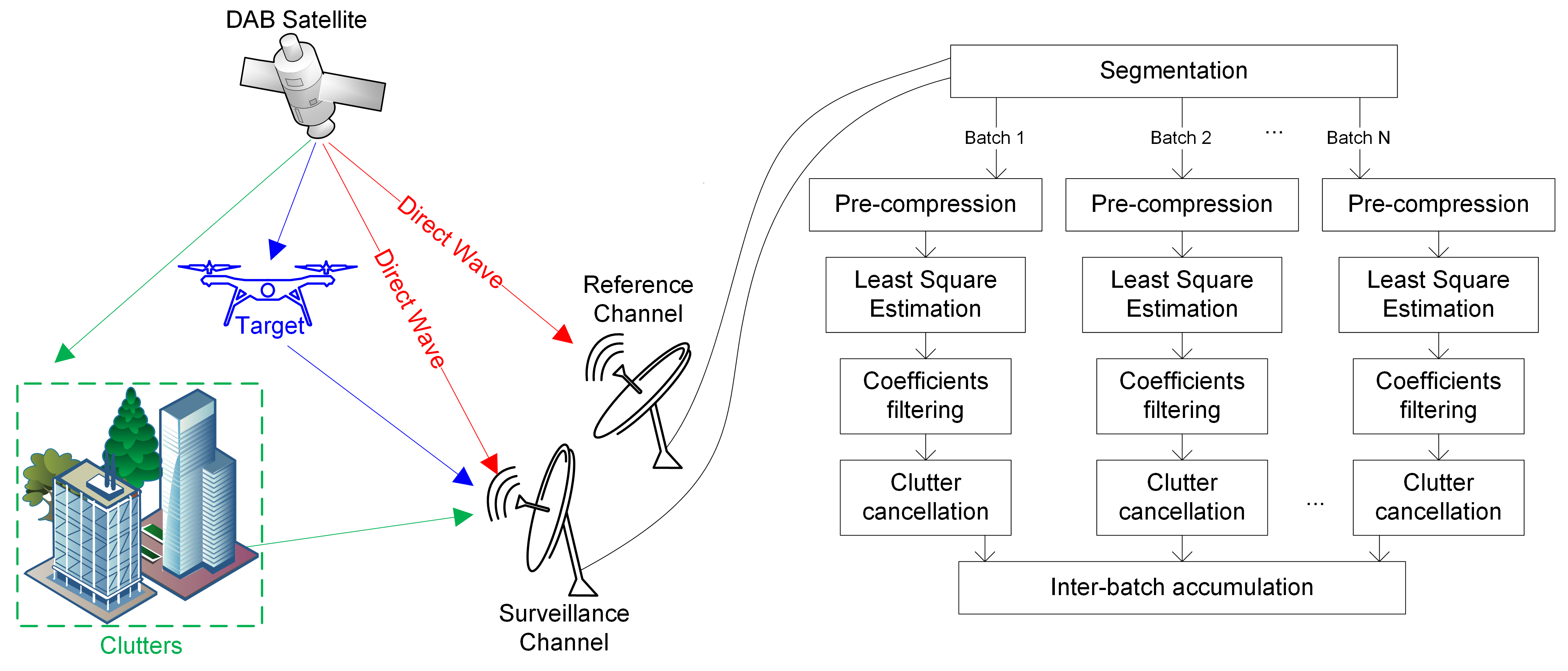
In practical processing, overlapped data can be included in each batch to complete the signal length to avoid the SNR loss caused by (20). As shown in Figure 2, the processing flow of ECA-C/LF with precompression (ECA-C/LF-PC) can be described as follows:
- (1)
- Signals of two channels are compressed by batches.
- (2)
- Least-square estimation of each batch is solved.
- (3)
- Coefficients are smoothed with low-pass filters.
- (4)
- Clutter component is canceled with the filtered estimations.
- (5)
- Two-dimensional cross-correlation function is obtained via inter-batch accumulation.
It needs to be re-emphasized that the derivation of ECA-C/LF is based on the assumption of an unchanged reference power. For scenarios where the illuminated power changes shape, the filter’s inputs need to be weighted according to the amplitude fluctuation such as in ECA-E [35]. Such a process is not discussed in this paper due to the stability of the satellite broadcast.
4. Performance Analysis
The computational cost and the clutter cancellation capability of ECA-C/LF are analyzed and contrasted in this section. Due to their advantages in convergence and intuitive parameters, the comparison is only among different ECA versions.
4.1. Computational Cost
Similar to [35], the computational cost is divided into two stages for all ECA versions: adaptive coefficients evaluation and clutter cancellation. For ECA-C/LF-PC, the additional compression for the reference channel is included in the first stage. For simplicity, let N denote the sampling length within a CPI, B indicate the total batch number, while L and K represent the number of range bins in the target area and suppression region, respectively.
In practical applications, the LS estimation is usually solved by matrix factorization and Gaussian elimination rather than inversion and multiplication in (10) for better efficiency and numerical accuracy.
If the evaluations are solved with uncompressed signals, a Cholesky factorization of is selected as is usually significantly larger than K and the hermitian sampling covariance matrix is positive-definite. On the other hand, for ECA-C/LF-PC, the calculation of and leads to no size reduction. Thus, a direct LU factorization of is a better choice, although its complexity is about twice that of a Cholesky factorization with the same size.
The total overheads within the evaluation stage of different ECA versions are calculated assuming that a complex addition involves two Flops, while a complex multiplication involves six Flops. The results are listed in Table 1, where denotes the sliding window length of ECA-S. The times of products and summations required for the factorization and other matrix calculations can be found in [37,38]. Similarly, the cost for the cancellation stage is derived as Flops for ECA-C/LF-PC and Flops for other versions since the sampling length N is consistent.
It can be found that, except for ECA-S, the increased overall Flops of ECA versions with a larger B can be neglected when , as the LS estimation costs much less than the sampling covariance matrix calculation or pulse compression. Standard ECA has the minimum complexity among all versions without precompression for applications with no Doppler extension, as the LS problem is solved only once in each CPI. However, only standard ECA needs an extended clutter base to form a wider notch, which can be achieved with a smaller batch length for ECA-B and ECA-S or filters with a broader passband for ECA-C/LF. Thus, the overall overhead of batched versions is much less in real applications, as the moving clutters cannot be neglected in most scenarios, and a wider notch and a wider notch can improve system robustness [31].
Moreover, a thorough segment can reduce the average overhead at each batch for ECA-B and ECA-ES, which is only valid with for ECA-C/LF-PC and for the non-precompressed version. The above boundaries are rarely reached as the second term in Table 1 cannot be neglected in this case, and the tolerance range seems excessive. It must be noticed that the precompression does not always reduce the total Flops. When , it is appropriate to only count the first term in Table 1, and a vague boundary can be given as
Since L and K have the same order of magnitude in close-range monitoring, the above formulation indicates the computational efficiency of precompression in such applications.
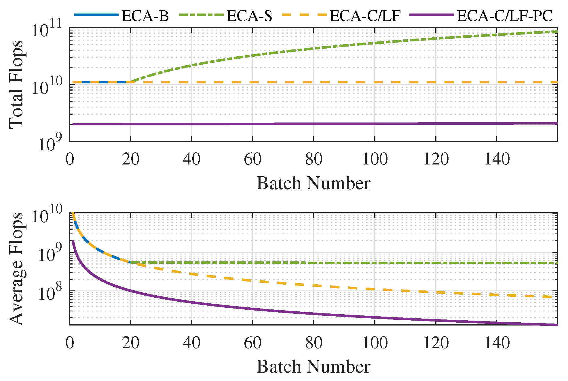
In order to better comprehend the above analysis, the total/average Flops of different ECA versions are shown in Figure 3, with , , , and . The maximum B of ECA-B and the minimum B of ECA-S are set at 20 to control the notch width. It should be noted that the curves only represent the trend of a Flops change, as only a few batch numbers can be selected to ensure uniform segmentation. As can be seen, precompression can reduce the Flops by about five times. Since the range of B is far from reaching the boundary in (24), the average Flops of all ECA versions monotonically decreases in the figure, except for ECA-S with a notable increasing total Flops.
Besides the Flops, precompression can significantly save memory usage when , bringing about better cache efficiency, which is much more critical for modern processors with high frequency [39]. The above benefit is tenable in the focused scenarios, as the low RCS of UAV results in a long accumulation time and the effective monitoring area is relatively small. In other words, the processing parameters include large N, and small K and L, which guarantees efficiency improvement under the complete segmentation needed in ECA-C/LF-PC. Although cache efficiency is difficult to evaluate before implementation, (24) is still a rough criteria for algorithm selection.
4.2. Suppression Capability
Notice that ECA-C/LF can be regarded as a linear, time-invariant system once the reference signal is determined, ensuring that the contribution from different clutters/targets to the cancellation vector could be calculated independently. Without loss of generality, only the on-grid echoes are discussed in this section, and the suppression capability of ECA-CF could be demonstrated based on the following simplified hypotheses similar to the following [34]:
- (1)
- The surveillance channel includes a stationary clutter and a moving target/clutter at the same range bin with a Doppler frequency of , in which the sampled vector becomes the following:where and are the complex amplitudes.
- (2)
- The correlation between the reference signal’s delayed replicas is negligible. Thus, the clutter base turns into a column vector:
- (3)
- The segmentation used by the 1D-CCF calculation is consistent with that of ECA-C/LF’s evaluation.
With the above assumptions, the estimation of each batch, or , is reduced to a single complex coefficient:
where indicates the noise component and represents the Doppler slice of the bth batch’s normalized ambiguity function without relative delay. For a constant modulus signal with normalized amplitude, it can be expressed as follows:
Equation (27) needs to be smoothed with a circular filter before clutter suppression. Assuming that and , the cancellation vector for each batch can be reconstructed as follows:
where is the filtered noise component and denotes the frequency response of , the definitions of which are as follows:
With the above formulation, the 1D-CCF of each batch’s canceled signal is
and the output of inter-batch accumulation compensated with a Doppler of can be expressed as
Compared with the ideal 2D-CCF output , the first term in (32) has a amplitude attenuation of
The above derivation applies to any for ECA-LF as the filter in (29) is replaced with a linear one.
Equation (33) reflects the attenuation degree of target echoes and clutters after processing, in which the approximate form under extreme cases should be taken into consideration for the parameter selection:
- (1)
- For fast-moving targets, , as is located in the filter’s stopband and . Thus, the batch segmentation needs to be thorough enough to ensure the reference signal’s Doppler tolerance range. Unfortunately, the flatness of near the origin makes the corresponding SNR improvement reduce sharply with larger B, while the total computation burden and temporary memory usage still maintain a fixed increase factor. In order to avoid unnecessary overhead, the targets’ Doppler range and allowed SNR loss should be designed first, with which the up-limited batch size can be determined based on the ambiguity function of the reference signal.
- (2)
- For slow-moving targets/clutters, , as . Since the clutter components need to be covered by the filter’s passband to avoid the masking effect mentioned above, target echoes around zero Doppler are suppressed to the same extent. A suitable notch width is crucial to preserving the detectability of low-speed targets. The filter weights can be designed based on the estimated suppression range for applications with stable clutter characteristics. While for time-varying scenarios, the passband can be adjusted in real-time according to the residual clutter power.
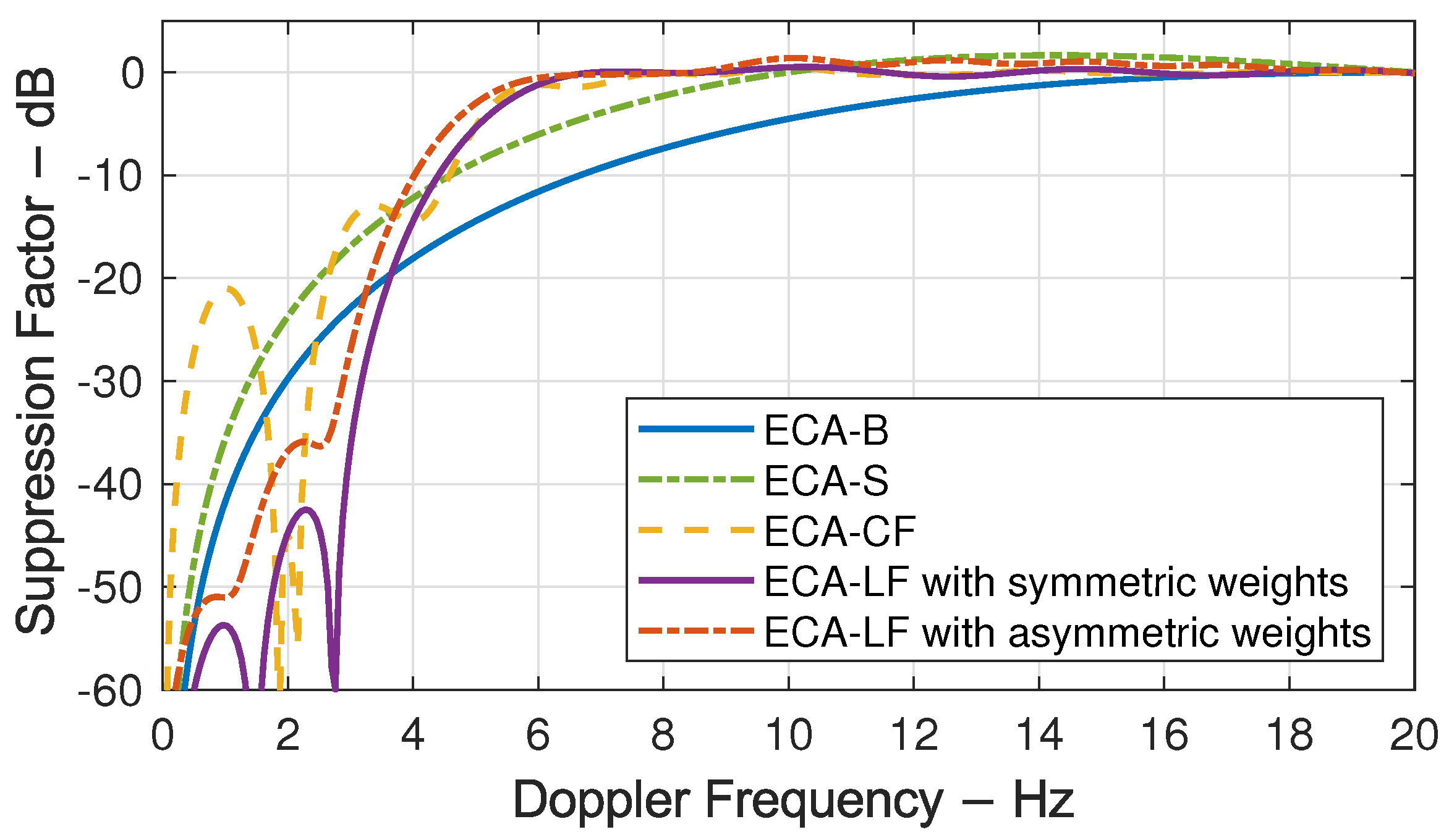
Compared with ECA-B, the Doppler ambiguity caused by segmentation is well prevented for ECA-C/LF, as the unambiguous range is much broader than the tolerance range if the allowed SNR loss caused by is limited. Moreover, ECA-C/LF can form a steeper notch edge, which is of great value for improving the detectability of low-speed targets. To better show these features, the suppression factor (SF) of a 3 MHz bandwidth DAB signal along the Doppler domain is compared between different ECA versions at a sampling frequency of 3.25 MHz. The ECA parameters are , , while the batch numbers of ECA-B, ECA-S, and ECA-C/LF are 10, 50, and 1000, respectively. The length of the sliding window used by ECA-S is . A 999-order symmetric lowpass filter with a 3 dB bandwidth of 8.8 Hz designed via the LS method is utilized by ECA-C/LF.
As shown in Figure 4, since the total sampling time is , the orthogonal frequencies are an integral multiple of 2 Hz, where ECA-CF and ECA-LF have the same performance. In contrast, for other frequencies within the filter’s 3 dB bandwidth, the performance of ECA-CF deteriorates obviously with a maximum value of 47 dB at and the area where SF is better than −20 dB is reduced from to . It can also be found that the difference between ECA-CF and ECA-LF is negligible outside the filter’s passband, and the sharp edge is well preserved. However, the SF provided by ECA-CF for moving clutters with is worse than ECA-B and ECA-S, which might influence the robustness and must be counted in practice to determine the applicability of ECA-CF.
As mentioned above, the process lag of ECA-LF can be reduced with asymmetric weights, for which the performance can be verified by a filter obtained with the same LS setting except for a reduced group delay of 100. Notice that it is precisely the extra delay caused by ECA-S when the sliding step is 1. The result shows that the asymmetric filter decreases the notch width a little while effectively retaining the sharp edge and that the SF deterioration is much weaker than that in ECA-CF. If can be divided by the step size, ECA-S can be approximated with ECA-LF using constant filter weights, for which the bandwidth can only be adjusted by the filter’s order. Using asymmetric coefficients, ECA-LF can apply higher-order filters with the same delay to achieve steeper edges, which is attractive in practical real-time processing.
5. Simulation
The same DAB illuminator in the above section was simulated with seven targets, the parameters of which are listed in Table 2, to further evaluate the performance of moving clutter rejection. The clutter region covers the first 41 range bins, for which the clutter-to-noise ratio (CNR) decreases linearly from 70 dB to 0 dB. An exponential power spectrum density (PSD) was used to model the fluctuation of clutters caused by moving scatters [40]:
where the stationary component is represented by the delta function multiplied with the power proportion factor r, while the moving clutters’ statistic characteristic is dependent on the radar wavelength and the shape factor determined by the wind speed. The above parameters were settled as and for all clutter cells.
The simulation was performed via Julia [41] on a desktop with Intel (R) Core (TM) i5-9600KF CPU at 3.7 GHz, and all ECA versions were implemented with the same parameters in Section 4.2, except for . Both ECA-C/LF were realized with precompression, and ECA with a Doppler extension ranging from −2 Hz to 2 Hz in steps of 1 Hz was also simulated. A 1000-point Taylor window with a maximum sidelobe level of 35 dB was applied to decrease the energy leakage alongside the Doppler domain, leading to an extra SNR loss of about 0.92 dB.
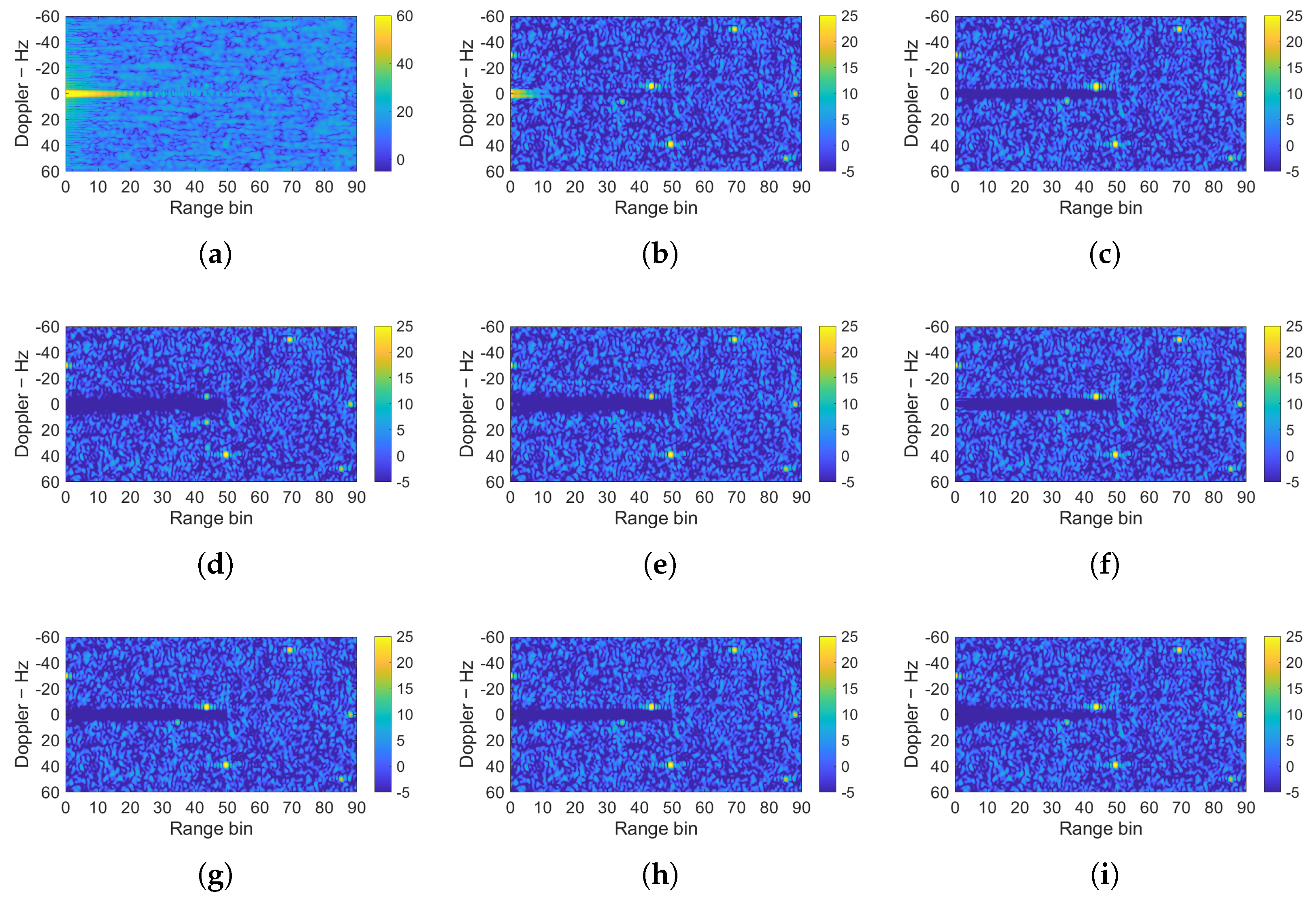
The 2D-CCFs, normalized according to the noise power, are compared in Figure 5, for which the consistent noise distribution verifies the rational approximation introduced in (23). The limited suppression of standard ECA without Doppler extension is verified by the strong residual in Figure 5b, although its influence on detection is mitigated to some extent by the Taylor window. On the contrary, all other versions can form a wider notch around the zero Doppler, leading to better robustness when dealing with moving clutters. Notice that some performance regression caused by ECA-CF’s discontinuity can be found at the notch’s edge in Figure 5f around the 0th range bin, for which the residual power has the same level as noise and is thus negligible in this example. The mentioned flexibility of ECA-C/LF can be comprehended with the triangular rejection area in Figure 5i, which is formed by a set of low-pass filters with linearly decreasing bandwidth. Since the clutter intensity usually decays with the increasing bistatic delay, similar processing can preserve the distant targets with low speed while removing the close clutter thoroughly.
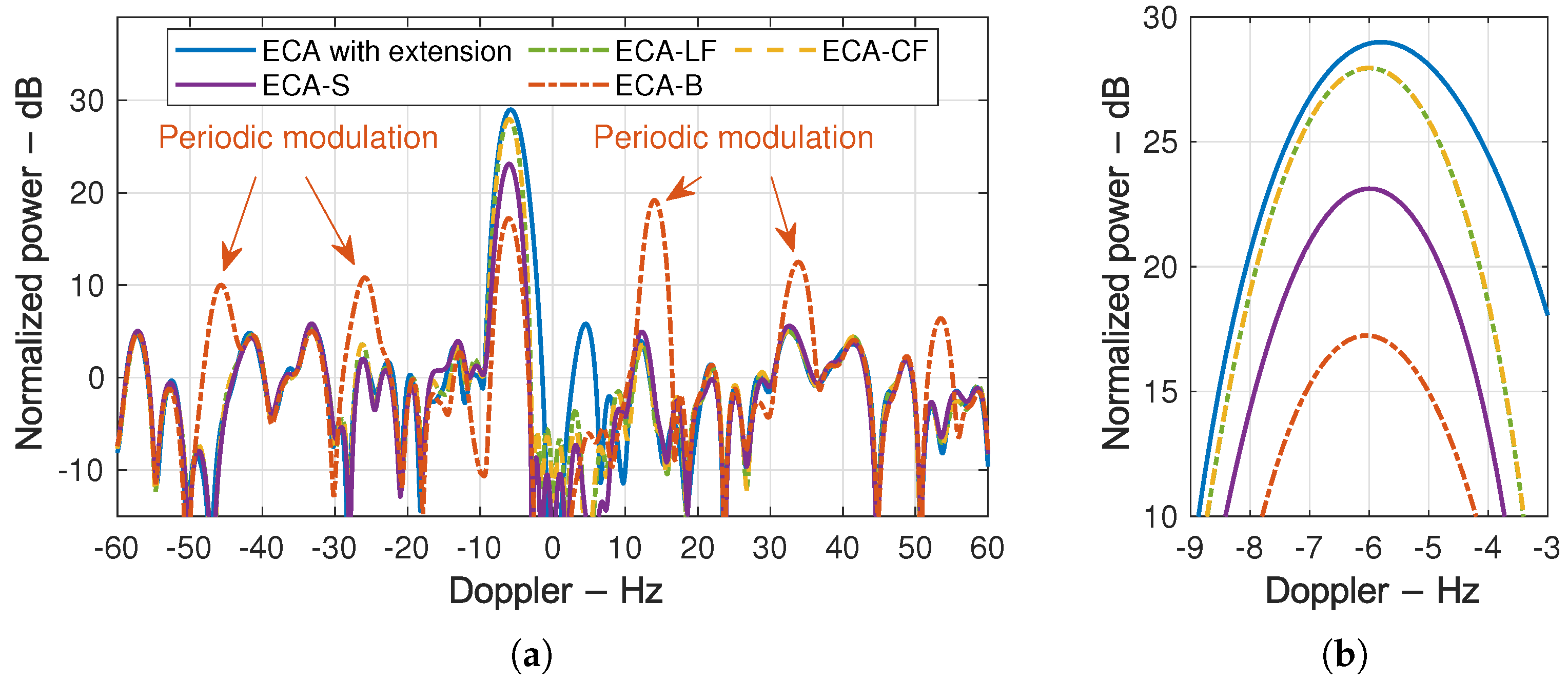
The Doppler slice of target three is shown in Figure 6 with its zoomed-in view to better indicate the influence of ECA-B’s Doppler ambiguity, where the periodic modulations are marked with arrows and the peak values at the target Doppler demonstrate the different retention of low-speed targets well. Although ECA with a Doppler extension has the highest output SNR, a Doppler offset of about 0.18 Hz could be found in the zoomed-in view, which has no effect on target detection but makes the Doppler estimation unbiased. A denser Doppler extension with a smaller step size can overcome this problem at the cost of extra SNR loss and computational burden.
In order to better compare the performance of different ECA versions, their time cost together with the third target’s SNR after suppression are measured and listed in Table 3, where the influence of Doppler ambiguity is also summarized. It can be found that the extra loss caused by ECA-LF, ECA-CF, ECA-S, and ECA-B is 0.45 dB, 1.11 dB, 5.95 dB, and 11.46 dB, respectively, for which the consistency with Figure 4 verifies the analysis in Section 4.2. Other than that, although ECA with Doppler extension performs best on target retention, its processing cost is far more than the other algorithms and thus impractical for real-time processing. In contrast, ECA-LF-PC can achieve a similar reservation performance with the minimal processing cost among all ECA versions.
6. Experimental Results
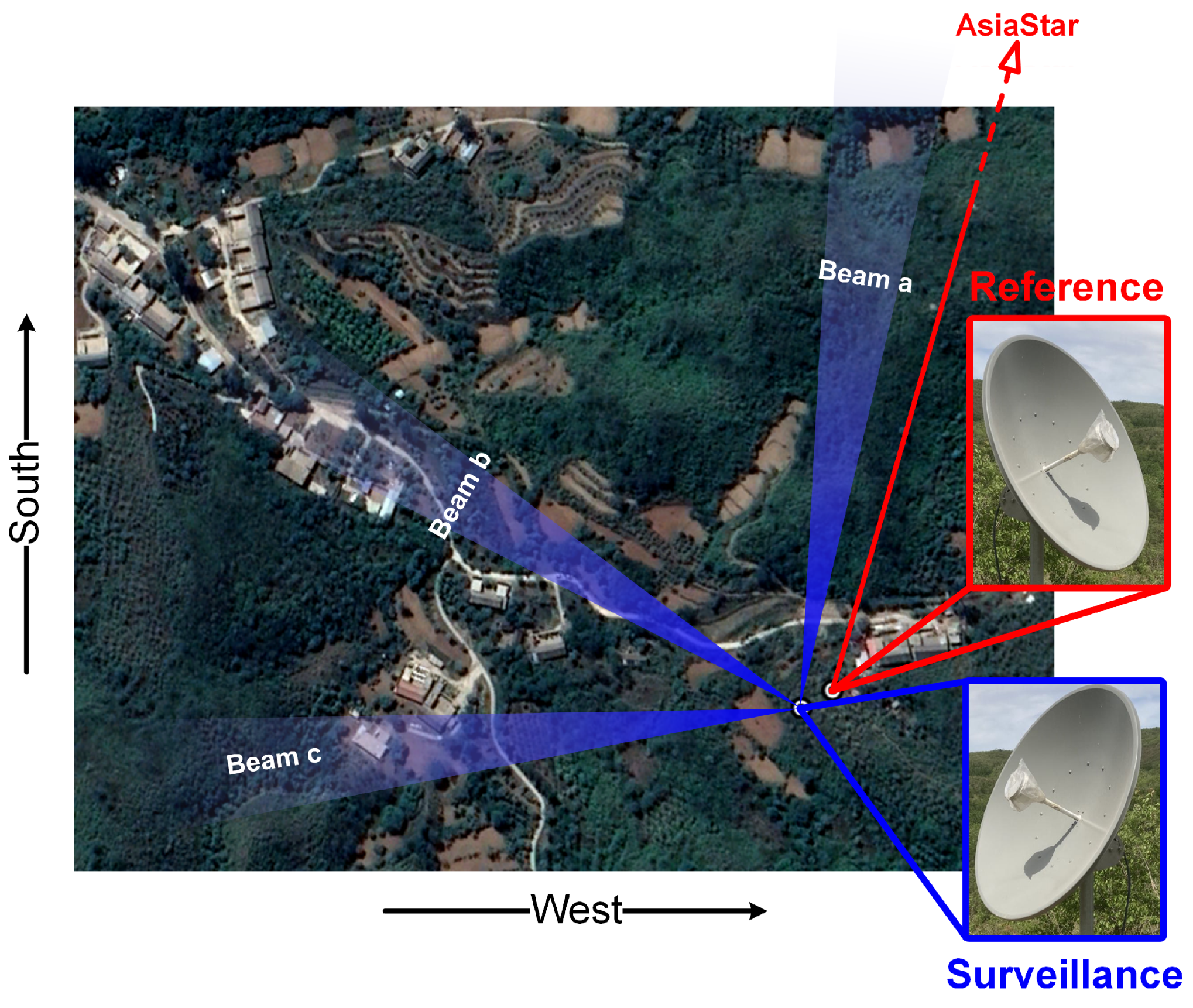
The experiments were carried out in May 2021 in YiXian, HeBei, China, with a receiver based on software-defined radio (SDR). Two identical parabolic antennas with a gain of 23.5 dBi in the frequency range of 1460 MHz to 1500 MHz were applied to the reference and surveillance channels, for which the 3 dB beamwidth is about . The geostationary DAB satellite, AsiaStar, was selected as the illuminator, the position and transmission parameters of which are listed in Table 4. The downlink channel with the best coverage, with a center frequency of 1469 MHz, was recorded at a sampling frequency of 3.125 MHz. A DJI’s amateur quadcopter for aerial photography, Phantom 4, was used as the non-cooperative target.
The observation geometry of the PBR system is shown in Figure 7, where an arrow from the reference antenna indicates the orientation towards the DAB satellite. Target echoes from three azimuths were collected to demonstrate the influence of the bistatic angle on the detection performance, and the corresponding surveillance beams are marked with different letters in Figure 7. The height of the UAV relative to the surveillance antenna was kept at 120 m during data acquisition, which lasted for 2 min for each beam.
Both ECA-LF and ECA-LF-PC were implemented using batch-level parallelism to analyze the efficiency gain brought by precompression. The parameters were set to , and a 300-order symmetric filter was employed for clutter suppression. The process was performed on the same desktop as in Section 6, during which all 375 million samples were prefetched into the memory at the first stage to reduce the impact of file loading. According to Table 1, precompression can reduce the Flops by about 80% with the above settings. In contrast, the profile shows that the overall costs for coefficient evaluation and cancellation of ECA-LF-PC are 0.33 s and 0.01 s, respectively, and those of the non-precompressed version are 1.32 s and 0.40 s, where the slight difference is acceptable considering that Flops is not the only factor determining the time cost. Compared with the benchmark results in Section 6, the time cost of ECA-LF-PC in experiments is reduced to about 40% because of the smaller K and larger .
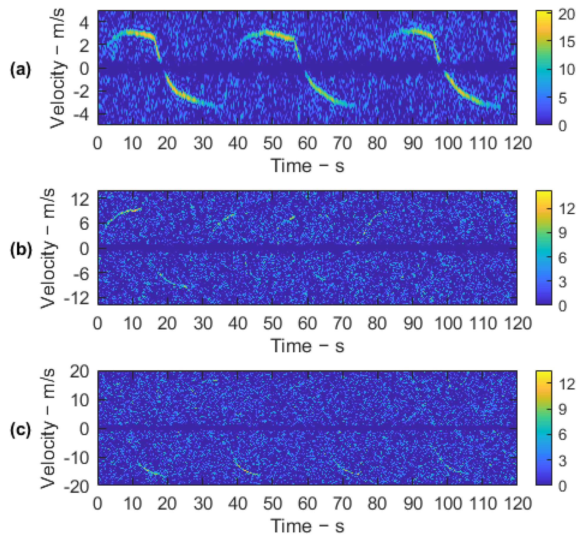
Due to the limited range resolution and fixed beams, the influence of UAV motion on the echo’s envelope is negligible during the analysis. Therefore, a short-time Fourier transform can be performed directly after the clutter suppression to observe the target’s varying bistatic velocity, which was applied to the range bins where the UAV locates to achieve an equivalent CPI of 0.5 s. The normalized energy distributions of different beams are shown in Figure 8, where the Doppler notch with the same width exists in all results because of the same filtering coefficients. Compared with the other two beams, an SNR improvement of more than 6 dB can be found in the first beam’s data because of the higher RCS brought by forward scattering. In contrast, although the backscattering geometry brings about higher bistatic velocity, the UAV is more challenging to be detected because of the lower echo energy.
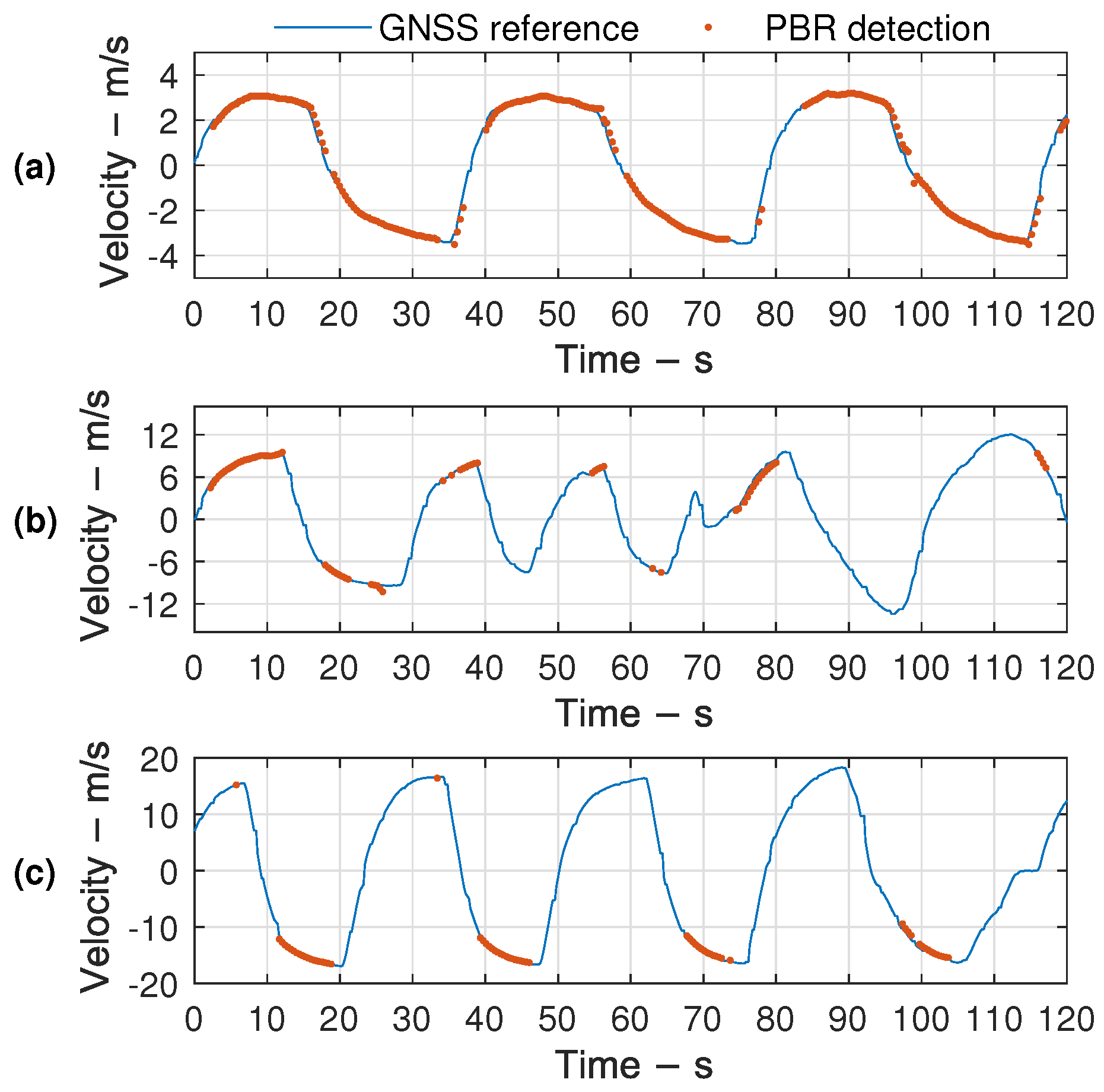
The CPI was increased to 2 s before detection to reduce the impact of a low SNR, where the high-order Doppler phase caused by the UAV’s acceleration was compensated by fractional Fourier transform. The corresponding results of the three data set are shown in Figure 9, in which the correctness can be verified by excellent alignment with the velocity reference calculated from a UAV’s GNSS data. The target in the first beam can be well detected outside the Doppler notch, and the interruptions of 37 s to 40 s and 78 s to 84 s could be attributed to the fixed surveillance beam. In contrast, the number of detectable CPI in the non-forward geometry is significantly reduced, leading to more apparent interruption. When located in the third beam, the UAV can hardly be detected when it moves toward the antenna, which indicates the influence of scattering fluctuation caused by the target attitude change.
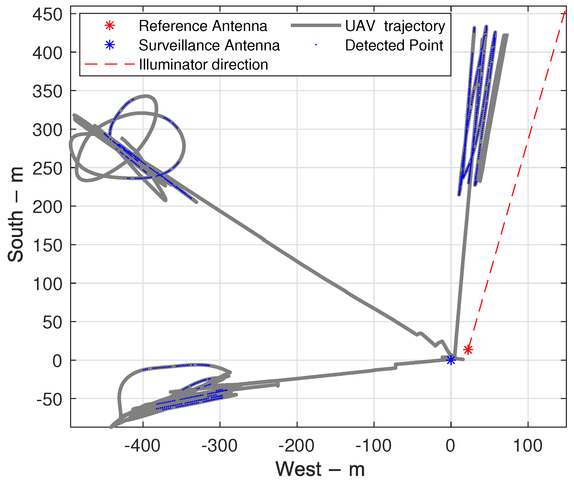
In order to analyze the monitoring range of the PBR system, the detected points associated with the UAV’s GNSS trajectory according to the timestamps are shown in Figure 10. The radial distances of the farthest detection are calculated in Table 5, where the maximum SNR and the proportion of detectable CPIs are also listed. The extra loss caused by long-time accumulation is found to be reduced by more than 1 dB in the forward scattering beam compared with the others, reflecting the influence of bistatic geometry on target scattering fluctuation to some extent. The different detectable proportions can be explained by the combination of such phenomena and the weaker scattering intensity. Although there is a massive gap in the other three indicators, the detectable distances of all the three data sets exceed 400 m, verifying the feasibility of the DAB satellite signal for UAV monitoring.
7. Discussion
UAV monitoring with PBR based on a DAB satellite is studied in this work, for which an advanced version of ECA is designed to suppress the multipath clutters with high efficiency in the focused close-range scene. Compared with the existing ECA versions, precompression is the key to efficiency gain, as the time cost is reduced via fewer Flops rather than improved parallelism. In practical systems, especially those using a multi-channel antenna for surveillance, the sampled data could be compressed in a batch after the acquisition and then transmitted to the host for subsequent cancellation and detection. The decreased demand for bus bandwidth further reduces the system cost.
Although the feasibility of target detection is demonstrated in Section 6, there are still some limitations in the experiments. First, the fixed antenna with narrow beamwidth leads to unavoidable echo-free data. Limited by calibration and measurement tools, it is difficult to obtain the accurate beam coverage of the experiments, and there might be some error in the proportion of detectable CPIs. Second, the UAV’s position was not estimated because of the limited bandwidth and the lack of angle measuring. As an alternative, the detectable range was obtained by the aligned UAV’s GNSS trajectory according to bistatic Doppler and timestamps during the data processing. Last but not least, although echos from the forward scattering region have much more vital energy, the capability of using it to expand the system’s detectable range is impractical because of the restricted observation geometry. Since the efficiency of coherent accumulation decreases with the increase in CPI, in order to further extend the detection range, an antenna with a higher gain is needed.
Possible future works include enlarging the observation azimuth of the system through multi-channel antennas, with which targets could be localized with the additional direction of arrival information. Other than that, the data fusion of multiple surveillance channels could be utilized to improve the position estimation accuracy.
8. Conclusions
In this paper, the detection of UAVs is addressed using PBR with a DAB satellite as an illuminator. The main work contained three parts. First, an advanced ECA version is designed to improve the efficiency of multipath clutter suppression via batch-level parallelism and precompression for close-range monitoring. Second, the proposed algorithm’s performance is analyzed and compared with the existing ECA versions, and the selection of its parameters is discussed and summarized. Theoretical derivation and numerical simulation show that the algorithm has better efficiency and preservation of slow targets. Finally, the experiments validate the feasibility of DAB satellite signals for UAV monitoring, in which the results demonstrate the influence of observation configuration and target attitude on the target’s detectability. For targets in non-forward beams, the system performance is vulnerable to fluctuation due to weak scattering while the forward geometry can significantly enhance the energy and thus improve the continuity of detection. The limitation of a fixed surveillance beam will be overcome with multi-channel antennas in future works.
Author Contributions
Conceptualization, Y.M. and J.L.; methodology, Y.M. and F.L.; software, Y.M.; formal analysis, Y.M. and Y.B.; writing—original draft preparation, Y.M.; visualization, Y.B.; writing—review and editing, F.L. and C.H.; project administration, C.H. and J.L. All authors have read and agreed to the published version of the manuscript.
Funding
This work was supported by the Special Fund for Research on National Major Research Instruments (grant No. 31727901) and the National Natural Science Foundation of China (grant No. 62071045 and grant No. 61625103).
Data Availability Statement
The data that support the findings of this study are available from the corresponding author, C.H., upon reasonable request.
Acknowledgments
The authors thank the editors and anonymous reviewers for their help comments and suggestions.
Conflicts of Interest
The authors declare no conflict of interest.
References
- Alizadeh, M.; Abedi, H.; Shaker, G. Low-cost low-power in-vehicle occupant detection with mm-wave FMCW radar. In Proceedings of the 2019 IEEE SENSORS, Montreal, QC, Canada, 27–30 October 2019; pp. 1–4. [Google Scholar] [CrossRef] [Green Version]
- Solla, M.; Lagüela, S.; Riveiro, B.; Lorenzo, H. Non-destructive testing for the analysis of moisture in the masonry arch bridge of Lubians (Spain). Struct. Control. Health Monit. 2013, 20, 1366–1376. [Google Scholar] [CrossRef]
- Fulton, J.W.; Anderson, I.E.; Chiu, C.L.; Sommer, W.; Adams, J.D.; Moramarco, T.; Bjerklie, D.M.; Fulford, J.M.; Sloan, J.L.; Best, H.R.; et al. QCam: SUAS-based Doppler radar for measuring river discharge. Remote Sens. 2020, 12, 3317. [Google Scholar] [CrossRef]
- Rasol, M.A.; Pérez-Gracia, V.; Solla, M.; Pais, J.C.; Fernandes, F.M.; Santos, C. An experimental and numerical approach to combine Ground Penetrating Radar and computational modeling for the identification of early cracking in cement concrete pavements. NDT E Int. 2020, 115, 102293. [Google Scholar] [CrossRef]
- Shin, D.H.; Jung, D.H.; Kim, D.C.; Ham, J.W.; Park, S.O. A Distributed FMCW Radar System Based on Fiber-Optic Links for Small Drone Detection. IEEE Trans. Instrum. Meas. 2017, 66, 340–347. [Google Scholar] [CrossRef]
- Laučys, A.; Rudys, S.; Kinka, M.; Ragulis, P.; Aleksandravičius, J.; Jablonskas, D.; Bručas, D.; Daugėla, E.; Mačiulis, L. Investigation of detection possibility of uavs using low cost marine radar. Aviation 2019, 23, 48–53. [Google Scholar] [CrossRef] [Green Version]
- Klare, J.; Biallawons, O.; Cerutti-Maori, D. UAV detection with MIMO radar. In Proceedings of the 2017 18th International Radar Symposium (IRS), Prague, Czech Republic, 28–30 June 2017; pp. 1–8. [Google Scholar] [CrossRef]
- Schüpbach, C.; Patry, C.; Maasdorp, F.; Böniger, U.; Wellig, P. Micro-UAV detection using DAB-based passive radar. In Proceedings of the 2017 IEEE Radar Conference (RadarConf), Seattle, WA, USA, 8–12 May 2017; pp. 1037–1040. [Google Scholar]
- Liu, Y.; Wan, X.; Tang, H.; Yi, J.; Cheng, Y.; Zhang, X. Digital television based passive bistatic radar system for drone detection. In Proceedings of the 2017 IEEE Radar Conference (RadarConf), Seattle, WA, USA, 8–12 May 2017; pp. 1493–1497. [Google Scholar]
- Samczynski, P.; Malanowski, M.; Krawczyk, G.; Kulpa, J.; Żywek, M. Passive radar as a part of critical infrastructure protection system. In Proceedings of the 2018 International Conference on Radar (RADAR), Brisbane, QLD, Australia, 27–31 August 2018; pp. 1–5. [Google Scholar]
- Poullin, D. Countering illegal UAV flights: Passive DVB radar potentiality. In Proceedings of the 2018 19th International Radar Symposium (IRS), Bonn, Germany, 20–22 June 2018; pp. 1–10. [Google Scholar]
- Vorobev, E.; Veremyev, V.; Tulenkov, N. Experimental DVB-T2 Passive Radar Signatures of Small UAVs. In Proceedings of the 2019 Signal Processing Symposium (SPSympo), Krakow, Poland, 17–19 September 2019; pp. 67–70. [Google Scholar]
- Martelli, T.; Colone, F.; Cardinali, R. DVB-T based passive radar for simultaneous counter-drone operations and civil air traffic surveillance. IET Radar Sonar Navig. 2020, 14, 505–515. [Google Scholar] [CrossRef]
- Geng, Z.; Xu, R.; Deng, H. LTE-based multistatic passive radar system for UAV detection. IET Radar Sonar Navig. 2020, 14, 1088–1097. [Google Scholar] [CrossRef]
- Seyfi, L. Measurement of electromagnetic radiation with respect to the hours and days of a week at 100 kHz–3 GHz frequency band in a Turkish dwelling. Measurement 2013, 46, 3002–3009. [Google Scholar] [CrossRef]
- Batool, S.; Bibi, A.; Frezza, F.; Mangini, F. Benefits and hazards of electromagnetic waves, telecommunication, physical and biomedical: A review. Eur. Rev. Med Pharmacol. Sci. 2019, 23, 3121–3128. [Google Scholar] [PubMed]
- Ilioudis, C.V.; Cao, J.; Theodorou, I.; Striano, P.; Coventry, W.; Clemente, C.; Soraghan, J. GNSS based passive radar for UAV monitoring. In Proceedings of the 2019 IEEE Radar Conference (RadarConf), Boston, MA, USA, 22–26 April 2019; pp. 1–6. [Google Scholar]
- Ilioudis, C.; Clemente, C.; Soraghan, J. GNSS-based passive UAV monitoring: A feasibility study. IET Radar Sonar Navig. 2019, 14, 516–524. [Google Scholar] [CrossRef] [Green Version]
- Ummenhofer, M.; Lavau, L.C.; Cristallini, D.; O’Hagan, D. UAV Micro-Doppler Signature Analysis Using DVB-S Based Passive Radar. In Proceedings of the 2020 IEEE International Radar Conference (RADAR), Washington, DC, USA, 28–30 April 2020; pp. 1007–1012. [Google Scholar]
- Martelli, T.; Cabrera, O.; Colone, F.; Lombardo, P. Exploitation of Long Coherent Integration Times to Improve Drone Detection in DVB-S based Passive Radar. In Proceedings of the 2020 IEEE Radar Conference (RadarConf20), Florence, Italy, 21–25 September 2020; pp. 1–6. [Google Scholar]
- Filippini, F.; Cabrera, O.; Bongioanni, C.; Colone, F.; Lombardo, P. DVB-S based Passive Radar for Short Range Security Application. In Proceedings of the 2021 IEEE Radar Conference (RadarConf21), Atlanta, GA, USA, 7–14 May 2021; pp. 1–6. [Google Scholar]
- Palmer, J.E.; Searle, S.J. Evaluation of adaptive filter algorithms for clutter cancellation in passive bistatic radar. In Proceedings of the 2012 IEEE Radar Conference, Atlanta, GA, USA, 7–11 May 2012; pp. 0493–0498. [Google Scholar]
- Garry, J.L.; Baker, C.J.; Smith, G.E. Evaluation of direct signal suppression for passive radar. IEEE Trans. Geosci. Remote Sens. 2017, 55, 3786–3799. [Google Scholar] [CrossRef]
- Liu, Y.; Yi, J.; Wan, X.; Zhang, X.; Ke, H. Evaluation of clutter suppression in CP-OFDM-based passive radar. IEEE Sens. J. 2019, 19, 5572–5586. [Google Scholar] [CrossRef]
- Malanowski, M. Signal Processing for Passive Bistatic Radar; Artech House: Norwood, MA, USA, 2019. [Google Scholar]
- Guan, X.; Hu, D.H.; Zhong, L.H.; Ding, C.B. Strong echo cancellation based on adaptive block notch filter in passive radar. IEEE Geosci. Remote Sens. Lett. 2014, 12, 339–343. [Google Scholar] [CrossRef]
- Zhao, Z.; Wan, X.; Shao, Q.; Gong, Z.; Cheng, F. Multipath clutter rejection for digital radio mondiale-based HF passive bistatic radar with OFDM waveform. IET Radar Sonar Navig. 2012, 6, 867–872. [Google Scholar] [CrossRef]
- Schwark, C.; Cristallini, D. Advanced multipath clutter cancellation in OFDM-based passive radar systems. In Proceedings of the 2016 IEEE Radar Conference (RadarConf), Philadelphia, PA, USA, 2–6 May 2016; pp. 1–4. [Google Scholar]
- Zhao, Z.; Zhou, X.; Zhu, S.; Hong, S. Reduced complexity multipath clutter rejection approach for DRM-based HF passive bistatic radar. IEEE Access 2017, 5, 20228–20234. [Google Scholar] [CrossRef]
- Bolvardi, H.; Derakhtian, M.; Sheikhi, A. Dynamic clutter suppression and multitarget detection in a DVB-T-based passive radar. IEEE Trans. Aerosp. Electron. Syst. 2017, 53, 1812–1825. [Google Scholar] [CrossRef]
- Colone, F.; O’hagan, D.; Lombardo, P.; Baker, C. A multistage processing algorithm for disturbance removal and target detection in passive bistatic radar. IEEE Trans. Aerosp. Electron. Syst. 2009, 45, 698–722. [Google Scholar] [CrossRef]
- Haykin, S.S. Adaptive Filter Theory; Pearson Education India: Delhi, India, 2008. [Google Scholar]
- Attalah, M.A.; Laroussi, T.; Gini, F.; Greco, M.S. Range-Doppler fast block LMS algorithm for a DVB-T-based passive bistatic radar. Signal Image Video Process. 2019, 13, 27–34. [Google Scholar] [CrossRef]
- Colone, F.; Palmarini, C.; Martelli, T.; Tilli, E. Sliding extensive cancellation algorithm for disturbance removal in passive radar. IEEE Trans. Aerosp. Electron. Syst. 2016, 52, 1309–1326. [Google Scholar] [CrossRef]
- Fu, Y.; Wan, X.; Zhang, X.; Yi, J.; Zhang, J. Parallel processing algorithm for multipath clutter cancellation in passive radar. IET Radar Sonar Navig. 2018, 12, 121–129. [Google Scholar] [CrossRef]
- Yoshida, T.; Aikawa, N. Transfer function of the reduced-delay low-pass maximally flat FIR digital differentiators. IEEJ Trans. Electron. Inf. Syst. 2016, 136, 157–164. [Google Scholar]
- Hunger, R. Floating Point Operations in Matrix-Vector Calculus; Munich University of Technology, Inst. for Circuit Theory and Signal: Munich, Germany, 2005. [Google Scholar]
- Golub, G.H.; Van Loan, C.F. Matrix Computations; JHU Press: Baltimore, MD, USA, 2013; Volume 3. [Google Scholar]
- Hennessy, J.L.; Patterson, D.A. Computer Architecture: A Quantitative Approach; Elsevier: Amsterdam, The Netherlands, 2011. [Google Scholar]
- Billingsley, J.B. Low-Angle Radar Land Clutter: Measurements and Empirical Models; IET: Washington, DC, USA, 2002. [Google Scholar]
- Bezanson, J.; Edelman, A.; Karpinski, S.; Shah, V.B. Julia: A fresh approach to numerical computing. SIAM Rev. 2017, 59, 65–98. [Google Scholar] [CrossRef] [Green Version]
Figure 1.
System diagram of PBR based on DAB satellite.

Figure 2.
Block diagram of the ECA-C/LF with precompression.

Figure 3.
Total and average Flops of different ECA versions.

Figure 4.
Suppression performance of different ECA versions.

Figure 5.
Two-dimensional cross-correlation function of different ECA versions. (a) Without suppression. (b) ECA without extension. (c) ECA with extension. (d) ECA-B. (e) ECA-S. (f) ECA-CF-PC. (g) ECA-LF-PC with symmetric weights. (h) ECA-LF-PC with asymmetric weights. (i) ECA-LF-PC with varying weights.

Figure 6.
The two-dimensional cross-correlation function’s Doppler slice of different ECA versions: (a) global view and (b) zoomed-in view.
Figure 6.
The two-dimensional cross-correlation function’s Doppler slice of different ECA versions: (a) global view and (b) zoomed-in view.

Figure 7.
The geometry configuration of the experiments: The surveillance and reference antennas are marked in blue and red, respectively. The direction of AsiaStar is indicated with a red arrow. Three surveillance beams, denoted with “Beam a/b/c”, of different azimuths were used during the experiments.

Figure 8.
SNR distributions of data from different orientations: (a) beam a, (b) beam b, and (c) beam c.
Figure 8.
SNR distributions of data from different orientations: (a) beam a, (b) beam b, and (c) beam c.

Figure 9.
Bistatic velocity of detection and the GNSS reference: (a) beam a, (b) beam b, and (c) beam c.
Figure 9.
Bistatic velocity of detection and the GNSS reference: (a) beam a, (b) beam b, and (c) beam c.

Figure 10.
Diagram of the system’s detectable range.


Table 1.
Flops of different ECA verisons within the evaluation stage.
| Algorithm | Flops |
|---|---|
| ECA | |
| ECA-B | |
| ECA-S | |
| ECA-ES | |
| ECA-C/LF | |
| ECA-C/LF-PC |
Table 2.
Target parameters.
| Target | 1 | 2 | 3 | 4 | 5 | 6 | 7 |
|---|---|---|---|---|---|---|---|
| SNR/dB | 25 | 17 | 30 | 28 | 25 | 20 | 20 |
| Range bin | 0 | 35 | 44 | 50 | 70 | 86 | 89 |
| Doppler/Hz | −30 | 6 | −6 | 39 | −50 | 50 | 0 |
Table 3.
Performance of different ECA versions.
| Algorithm | SNR of Target Three/dB | Periodic Modulation | Time Cost/ms |
|---|---|---|---|
| ECA with extension | 29.02 | No | 1755.17 |
| ECA-B | 17.62 | Yes | 23.13 |
| ECA-S | 23.13 | No | 113.84 |
| ECA-LF-PC | 28.63 | No | 3.62 |
| ECA-CF-PC | 27.97 | No | 3.62 |
Table 4.
Parameters of AsiaStar.
| Parameter | Value |
|---|---|
| Longitude | |
| Inclination | |
| Perigee altitude | 35,776 km |
| Apogee altitude | 35,811 km |
| EIRP | 53 dBw |
| Downlink bandwidth (single channel) | 1.84 MHz |
Table 5.
Detection performance of different beams.
| Beam a | Beam b | Beam c | |
|---|---|---|---|
| Maximum distance/m | 452.6 | 551.6 | 416.7 |
| Maximum SNR/dB (CPI = 0.5 s) | 20.57 | 14.25 | 13.51 |
| Maximum SNR/dB (CPI = 2 s) | 25.44 | 17.76 | 16.73 |
| Proportion of detectable CPIs | 85.5% | 26.0% | 22.5% |
Publisher’s Note: MDPI stays neutral with regard to jurisdictional claims in published maps and institutional affiliations. |
© 2021 by the authors. Licensee MDPI, Basel, Switzerland. This article is an open access article distributed under the terms and conditions of the Creative Commons Attribution (CC BY) license (https://creativecommons.org/licenses/by/4.0/).
Share and Cite
MDPI and ACS Style
Miao, Y.; Li, J.; Bao, Y.; Liu, F.; Hu, C. Efficient Multipath Clutter Cancellation for UAV Monitoring Using DAB Satellite-Based PBR. Remote Sens. 2021, 13, 3429. https://0-doi-org.brum.beds.ac.uk/10.3390/rs13173429
AMA Style
Miao Y, Li J, Bao Y, Liu F, Hu C. Efficient Multipath Clutter Cancellation for UAV Monitoring Using DAB Satellite-Based PBR. Remote Sensing. 2021; 13(17):3429. https://0-doi-org.brum.beds.ac.uk/10.3390/rs13173429
Chicago/Turabian StyleMiao, Yingjie, Jingchun Li, Yao Bao, Feifeng Liu, and Cheng Hu. 2021. "Efficient Multipath Clutter Cancellation for UAV Monitoring Using DAB Satellite-Based PBR" Remote Sensing 13, no. 17: 3429. https://0-doi-org.brum.beds.ac.uk/10.3390/rs13173429
Note that from the first issue of 2016, this journal uses article numbers instead of page numbers. See further details here.