
Motion Phase Compensation Methods for Azimuth Ambiguity Suppression in HRWS SAR
by
 ,
,
Junying Yang
1,2,3, 
Xiaolan Qiu
1,2,3,* ,
,
Mingyang Shang
1,2,3,
Lihua Zhong
1,2,3 and
Chibiao Ding
1,3,4 1
Aerospace Information Research Institute, Chinese Academy of Sciences, Beijing 100094, China
2
Key Laboratory of Technology in Geo-Spatial Information Processing and Application Systems, Institute of Electronics, Chinese Academy of Sciences, Beijing 100190, China
3
School of Electronic, Electrical and Communication Engineering, University of Chinese Academy of Sciences, Beijing 100049, China
4
National Key Laboratory of Microwave Imaging Technology, Institute of Electronics, Chinese Academy of Sciences, Beijing 100190, China
*
Author to whom correspondence should be addressed.
Remote Sens. 2021, 13(17), 3543; https://0-doi-org.brum.beds.ac.uk/10.3390/rs13173543
Submission received: 26 July 2021
/
Revised: 2 September 2021
/
Accepted: 4 September 2021
/
Published: 6 September 2021
(This article belongs to the Section Remote Sensing Communications)
Abstract
:The azimuth multi-channel synthetic aperture radar (SAR) is widely used in marine observation, because of its excellent imaging ability of high-resolution and wide-swath (HRWS) signals. Different from the static targets, the azimuth ambiguity of the ships on the open sea resulting from the radial motion seriously affects the SAR image quality and ship detection probability. As a result, two methods of azimuth ambiguity suppression for moving ships based on motion phase compensation are proposed to apply to different practical application conditions. The simulation and real measured data experiments verify the ability of image quality improvement by proposed methods.

1. Introduction
Geometric resolution and imaging coverage swath are always two major performance indicators of synthetic aperture radar (SAR) images. However, the traditional single-channel SAR system cannot realize high-resolution and wide-swath (HRWS) imaging simultaneously because of their conflicting requirements for the pulse repetition frequency (PRF) setting of the transmitter [1]. The azimuth multi-channel SAR has been a considerable technology to produce HRWS images in recent years, which broke through the inherent limitation of traditional SAR [2,3]. To avoid range ambiguity, the antenna phase center transmits the signal at the PRF lower than the Doppler bandwidth. Combined with the advanced digital signal processing technology on the receiver to improve the geometric resolution. Therefore, the most significant feature of the azimuth multi-channel SAR is that the data of a certain channel cannot be imaged separately, and the data of multiple channels must be equivalent to the full-sampling data of a traditional single-channel before imaging.
HRWS SAR is an effective tool for ocean scenes that need wide-area and real-time monitoring. As for maritime moving ship targets, the additional radial motion results in serious azimuth ambiguity after the imaging algorithm, which is different from the static scenes [4]. The performance of azimuth ambiguity in the image is that there are several pairs of false targets whose intensity decreases in turn on both sides of the real target [5,6,7,8,9,10]. The existence of false targets seriously degrades the image quality, as well as increases the false alarm rate of subsequent ship target detection.
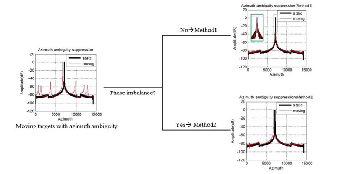
There have been some studies on moving target unambiguous imaging algorithms. Baumgartner et al. proposed that the reconstruction of a moving target can be achieved by maximizing the signal-to-noise ratio (SNR) by using matched reconstruction filter bank (MRFB) [5]. Because of the iterative operation, the algorithm requires a large amount of computation and has poor timeliness. Zhang et al. used the prior knowledge of the radial velocity to set up an appropriate filter to extract each ambiguous component and got the complete spectrum free from ambiguity [6]. Similarly, Yang et al. estimated the radial velocity of the target based on the sparse direction-of-arrival (DOA) estimation and then used space-time adaptive processing (STAP) to suppress clutter and image the moving target [7]. As we all know, the most inevitable problem of STAP is the huge amount of computation. Jin et al. proposed a moving target reconstruction filter method based on known radial velocity to obtain the unambiguous spectrum [8]. Although the methods improve the image quality of moving targets, they are developed for a single target. For the HRWS SAR images, the number of moving targets is usually more than one. Then, the existing methods need to be iterated many times. Therefore, the reason why they have a large amount of computation is mainly due to the algorithm complexity for a single target and iteration operation dealing with multiple targets. Besides, the residual phase errors between channels will affect the accuracy of velocity estimation [9]. Therefore, the improvement of ocean scene image quality will have poor performance when the imbalance between channels cannot be completely corrected. Also, the phase error estimation in ocean scenes has always been a difficult problem. In [10], the unambiguous imaging scheme of moving ships for maritime scenarios is proposed. Based on the imaging scheme, this letter will propose two motion phase compensation methods to suppress the azimuth ambiguity of marine moving targets. The proposed two methods are suitable for the cases that the phase imbalance between channels is completely corrected and the residual phase imbalance between channels cannot be ignored, respectively.
This communication is organized as follows: Short reviews of the multichannel HRWS SAR signal model of moving target are presented in Section 2; In Section 3, two methods of motion phase compensation are described in detail; Section 4 gives results of the simulation data and real data experiments, and the conclusions in Section 5 close the technical note.
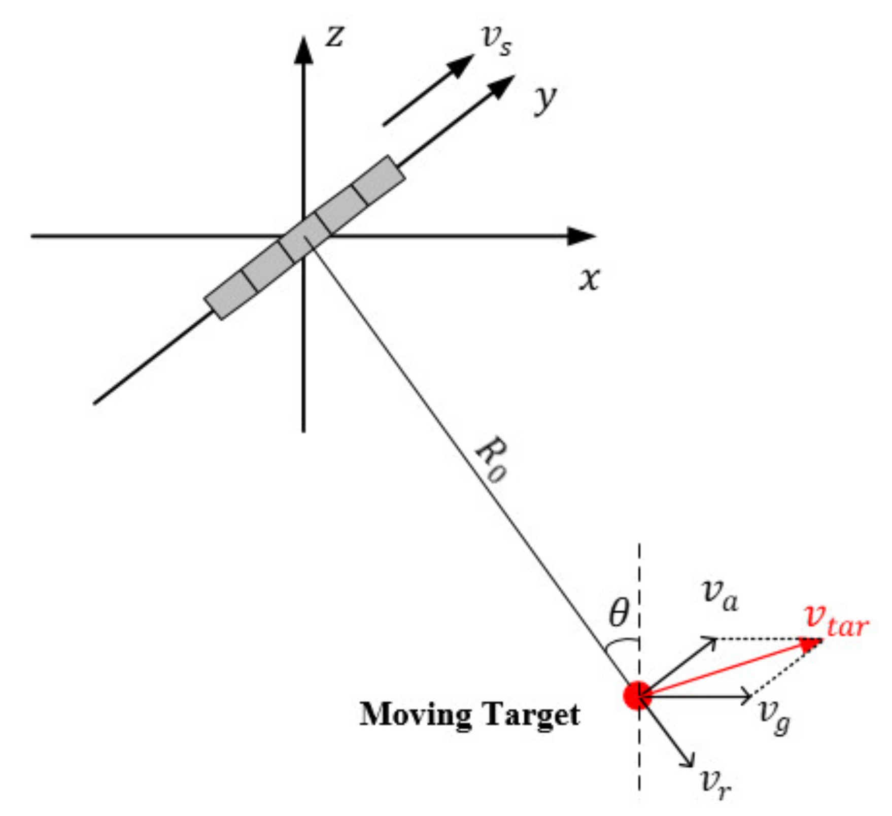
2. Signal Model
The geometry of the azimuth multichannel SAR system is illustrated in Figure 1. The azimuth direction is along the y-axis, and platform velocity is presented as . There is a moving target in the imaging scene, whose shortest slant range is and the incident angle is . It is supposed that the velocity of the target along the ground is . In general, the velocity is decomposed into the along-track velocity and the cross-track velocity . The radial velocity is the projection of the cross-track velocity in the slant range direction. During the continuous illumination of the SAR sensor, the radial velocity of the target is considered as a constant value reasonably. In this letter, we only focus on the radial velocity, because it is the main factor causing azimuth ambiguity.
According to the imaging geometry, the instantaneous slant range between the n-th channel and the moving target can be expressed as:
where:
The distance between two receive phase centers is , and represents the initial coordinates of the target.
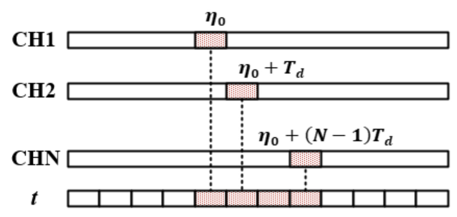
It assumed that the channels are completely consistent, and the system parameters satisfy the uniform sampling condition [4]. And we use for the azimuth time of the single-channel sampling as shown in Figure 2, i.e.,
In such a situation, for the static target (), when the data of multiple channels are cross arranged, the equivalent single-channel echo is written as:
The instantaneous slant range expression of the static target is consistent with that in traditional SAR after reconstruction [11]. For a moving target, however, the equivalent single-channel echo is written as:
where:
Therefore, when the target has radial motion, the reconstructed signal is no longer equivalent to the single-channel uniformly sampled signal but introduces a phase error along the channel dimension.
The essential reason for the existence of false targets is the periodic extension of the spectrum when the data sampling of each channel does not satisfy the sampling theorem. If there are no errors between channels, the ambiguous parts of the signal spectrum can cancel each other after multi-channel data reconstruction. However, when the amplitude or phase of the channel is imbalanced, the ambiguous parts cannot be offset, resulting in false targets. In an HRWS SAR image, even if the channel imbalance is compensated and the unambiguous spectrum of the scene is obtained after the reconstruction algorithm, the echo of the moving target still suffers from additional phase errors, which leads to obvious azimuth ambiguity in the image. Moreover, the location of the false targets is expressed as:
where represents PRF of the system and is Doppler rate. Thus, the number of false targets is generally . When , the false target is introduced by the sidelobe of the antenna pattern.
3. Methods
In this section, the azimuth ambiguity is suppressed by motion phase compensation for the echo of moving targets. In the processing of multi-channel data of maritime scenarios, the phase imbalance between channels can be corrected accurately according to the internal calibration information or estimated value [3,12]. In such a situation, the radial velocity of the marine ship can be estimated correctly to suppress false targets and realize relocation. It is worth mentioning that there have been some relatively efficient and accurate radial velocity estimation algorithms, i.g., the subspace-based method (SBM), and the modified frequency correlation method (MFCM) [9]. However, strong noise or too many vessels will affect the phase error estimation performance and even cause phase error estimation unavailable for ocean scenes. The residual phase error leads to inaccurate velocity estimation, which results in the poor effect of azimuth ambiguity suppression [9]. In order to suppress the azimuth ambiguity and improve the image quality of ocean scenes under different practical application conditions, two motion phase compensation methods will be introduced in detail based on the imaging scheme in [10].
3.1. Method 1
After range compression, the expression of the echo in the range frequency domain is as follows: (for the convenience of expression and without losing generality, the amplitude of the received signal is ignored):
where and represent the range frequency and radar frequency. And represents the speed of light. The wavelength of the carrier is expressed as .
For a static target, the received signal of -th channel can be written as:
while for a moving target, the echo of -th channel is expressed as:
From (1), the relationship between the static target and the moving target is:
where:
After motion phase compensation, the echo of the moving target is equivalent to that of the static target in each channel. From (12), there are two terms in the compensation phase: the first term is the range walk of the range cell migration curve caused by the radial motion; the second one is the Doppler center shift result in the position deviation in the azimuth direction.
In summary, the compensation function (12) is calculated based on the radial velocity estimation, and the moving target is completely equivalent to the stationary one so that the azimuth ambiguity is suppressed. Meanwhile, the misplaced target returns to the right position by correcting the Doppler shift.
3.2. Method 2
For method 1, the higher the accuracy of velocity estimation, the higher the accuracy of relocation, and the better the performance of false target suppression. However, the velocity estimation is sensitive to the residual phase error between channels. If the users only have high requirements for image quality, the additional phase errors caused by radial motion in the echo of the moving target can be compensated directly, so as to achieve false target suppression. Therefore, what we focus on is the relationship of the signal between the -th channel and the reference channel (-th channel). The instantaneous slant range of -th channel can be written as:
Thus, the expression of the echo in the range frequency domain is as follows:
where:
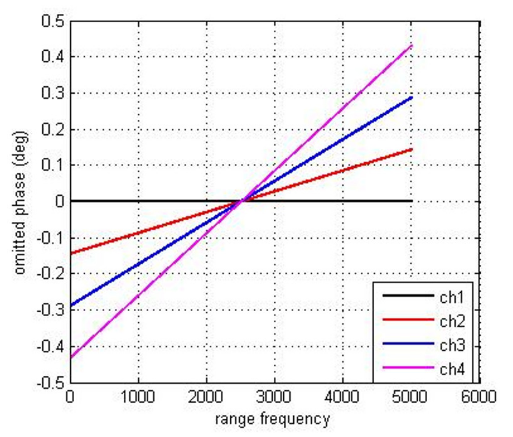
Given that the frequency of spaceborne SAR usually reaches GHz level, i.e., , the first term of the compensation function (15) can be ignored. Consequently, the signal of each channel is equivalent to that of the reference channel after a simple time delay by correcting the linear phase error along the channel dimension. The motion phase compensation function is approximately by:
It is implied in (16) that the influence of radial velocity on the multi-channel signal of a moving target is mainly reflected in the additional phase error. If the prior knowledge of radial velocity is unknown, the aim of azimuth ambiguity suppression can be achieved by estimating and compensating phase imbalance for the echo of the moving target directly. The effective phase imbalance estimation methods are the signal subspace comparison method (SSCM) [3] and frequency domain correlation method (FDCM) [12], et al. After channel imbalance correction, the reconstructed is completely equivalent to the moving target echo of the traditional single-channel SAR, which is written as:
where:
Compared with Equations (5) and (18), the core idea of Method 2 is to make the multi-channel echo equivalent to the traditional single-channel echo by compensating the motion phase. The azimuth ambiguity is suppressed, while the position deviation caused by radial motion still exists.
4. Experimental Results
4.1. Simulation Data
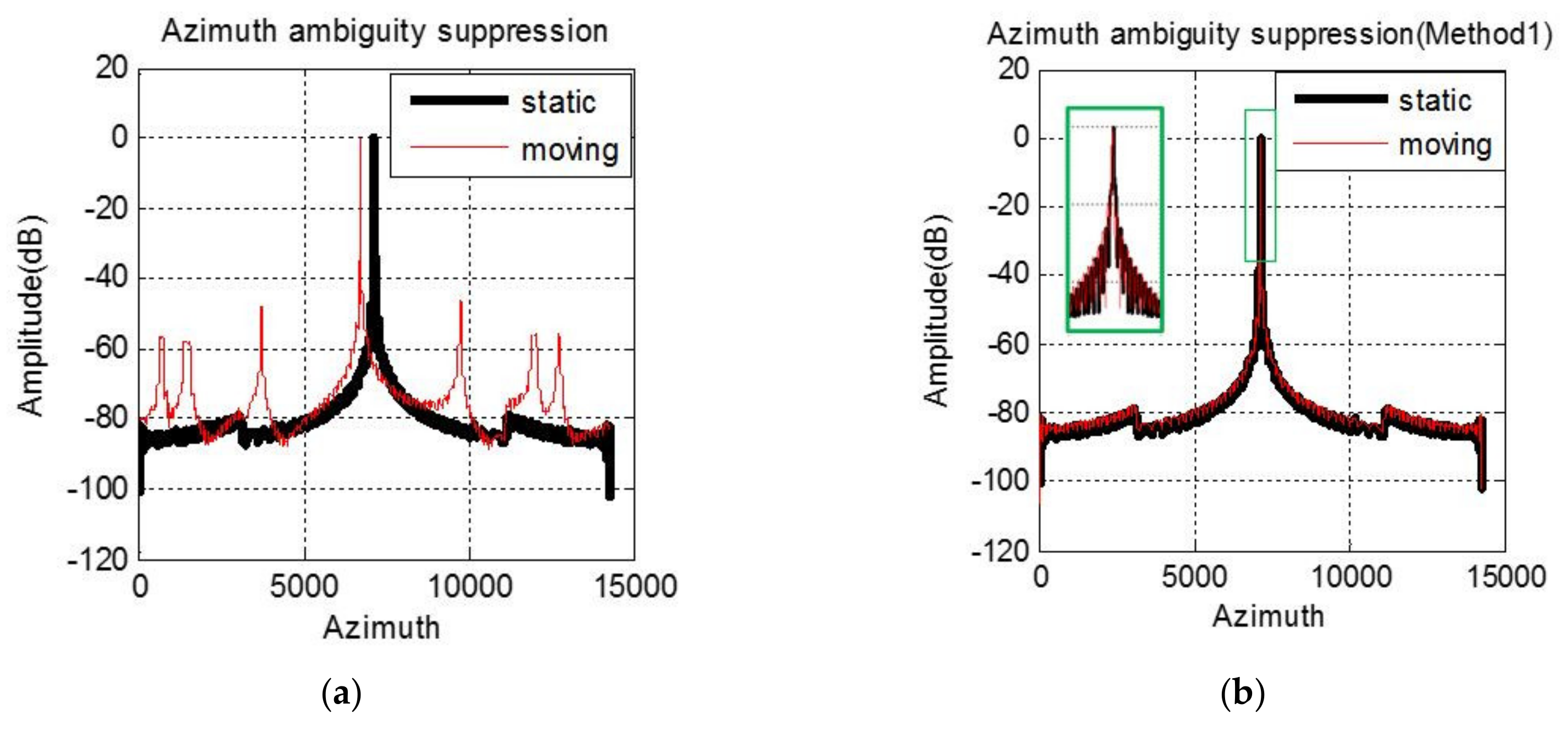
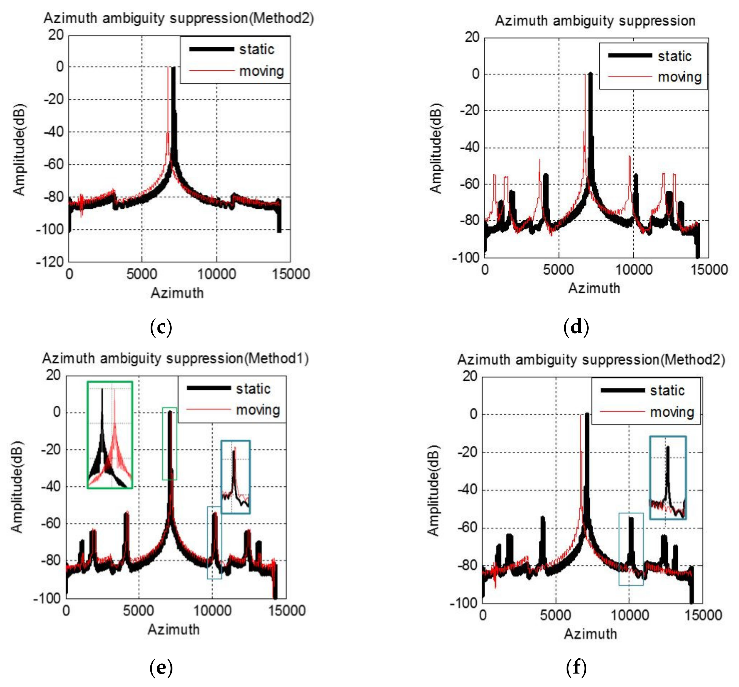
A C-band azimuth four-channel SAR system is simulated to verify the difference of moving target imaging before and after motion phase compensation under different experimental conditions. The wavelength and PRF of the simulated SAR system are 0.056 m and 1189.8 Hz. The bandwidth and sampling rate of the signal is 106 MHz and 127 MHz. The antenna baseline is 1.5 m. The platform moves at the speed of 7614 m/s. A static target and a moving target with a radial velocity of 5 m/s are simulated in the experiment, and they are located in the same azimuth position. We simulate two possible cases in the actual processing: the first case is that the phase error between channels is compensated successfully shown as in Figure 3a–c while the second case is that there is residual phase error shown as in Figure 3d–f which shows the azimuth envelope of the imaging result under different situations. When the phase characteristics of multi-channel are completely consistent, the static target is free from the azimuth ambiguity, while the moving one has obvious false targets along the azimuth direction, which is shown in Figure 3a. In this case, the radial velocity estimation result of the moving target is 4.98 m/s. After motion phase compensation with Method 1, the false target is greatly suppressed and relocated to the same position as the static one, which is illustrated in Figure 3b. From Figure 3c, although the position of the moving target remains unchanged, the unambiguous imaging result is also obtained with Method 2. However, if there is residual phase error between channels, not only the moving targets but also the static ones will suffer from the azimuth ambiguity, shown as in Figure 3d. In this case, the estimated radial velocity is 5.82 m/s, which deviates from the real value of 5 m/s. Therefore, with Method 1, both the false targets suppression and relocation fail, which is illustrated in Figure 3e. But the azimuth ambiguity is suppressed successfully in Method 2, shown in Figure 3f. For the ocean scene with only bright ships in the open sea, Method 2 has extremely important application value. For Method 2, because the radial velocity cannot be estimated accurately, we approximate the compensated phase (15) to (16). Figure 4 shows the omitted phase terms of each channel for the simulated four-channel SAR system, which is the phase value varying with range frequency. The maximum value does not exceed 0.5 degrees, which has little influence on image quality. Therefore, the proposed method is reasonable.
4.2. GF-3 UFS Mode Data
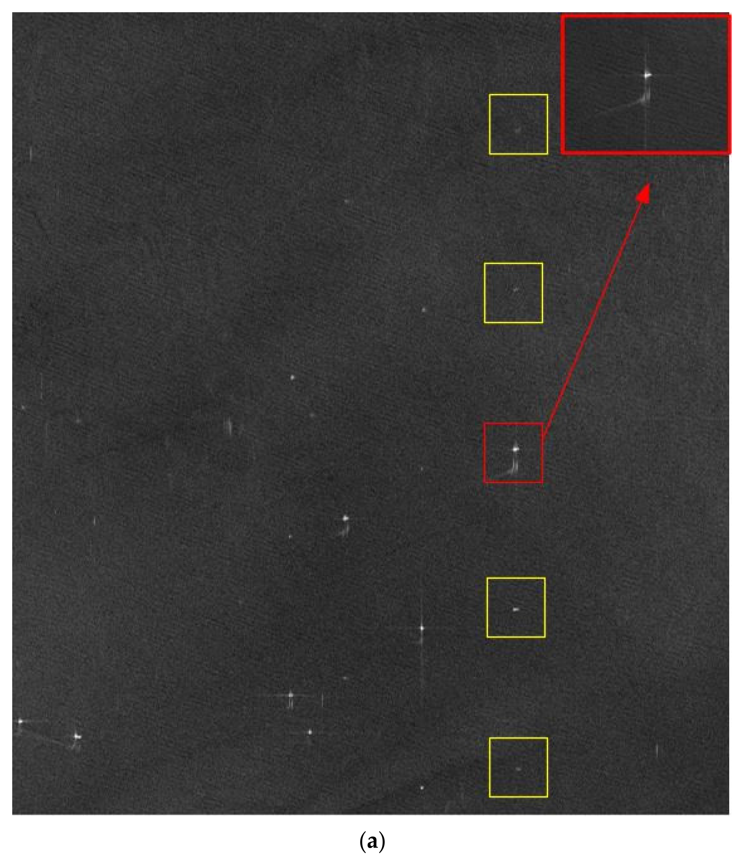
Figure 5a shows the HRWS ocean scene SAR image obtained by GaoFen-3 (GF-3) satellite in ultra-fine stripmap (UFS) imaging mode on 2 July 2018. From Figure 5a, we can see the false targets on both sides of the real target marked with a red box. And the false targets are marked with yellow boxes. The serious azimuth ambiguity makes the SAR image appear disorderly. Besides, from the wake of the ship in the red box, it can be judged that the ship deviates from the correct position, which is caused by the radial velocity. To suppress the azimuth ambiguity, this letter adopts the imaging scheme in [10], and the results of two motion phase compensation methods are compared with each other.
GF-3 is the first azimuth multi-channel SAR system in China, and its phase imbalance correction performance for the land scenes is stable. In boot time in UFS mode, GF-3 can acquire dozens of SAR images. These images usually contain rich scenes, including ocean, land, and the ocean-land boundary. However, the phase imbalance of these data can be considered to be the same [12]. Due to the low signal-to-noise ratio (SNR) of ocean scene echo data, the phase error estimation has always been a difficult problem to be solved. For the land scene echo data with high SNR, the phase error estimation result is accurate and stable. Therefore, the phase error estimation results of adjacent land scenes are used to compensate for the phase inconsistency of ocean scene echo data. Subsequently, the radial motion information is obtained by the method in [9]. The ships in Figure 5a are numbered from left to right, and the radial velocities of the seven ships are listed in Table 1. The signal-to-clutter ratios (SCR) are measured in the range compression domain.
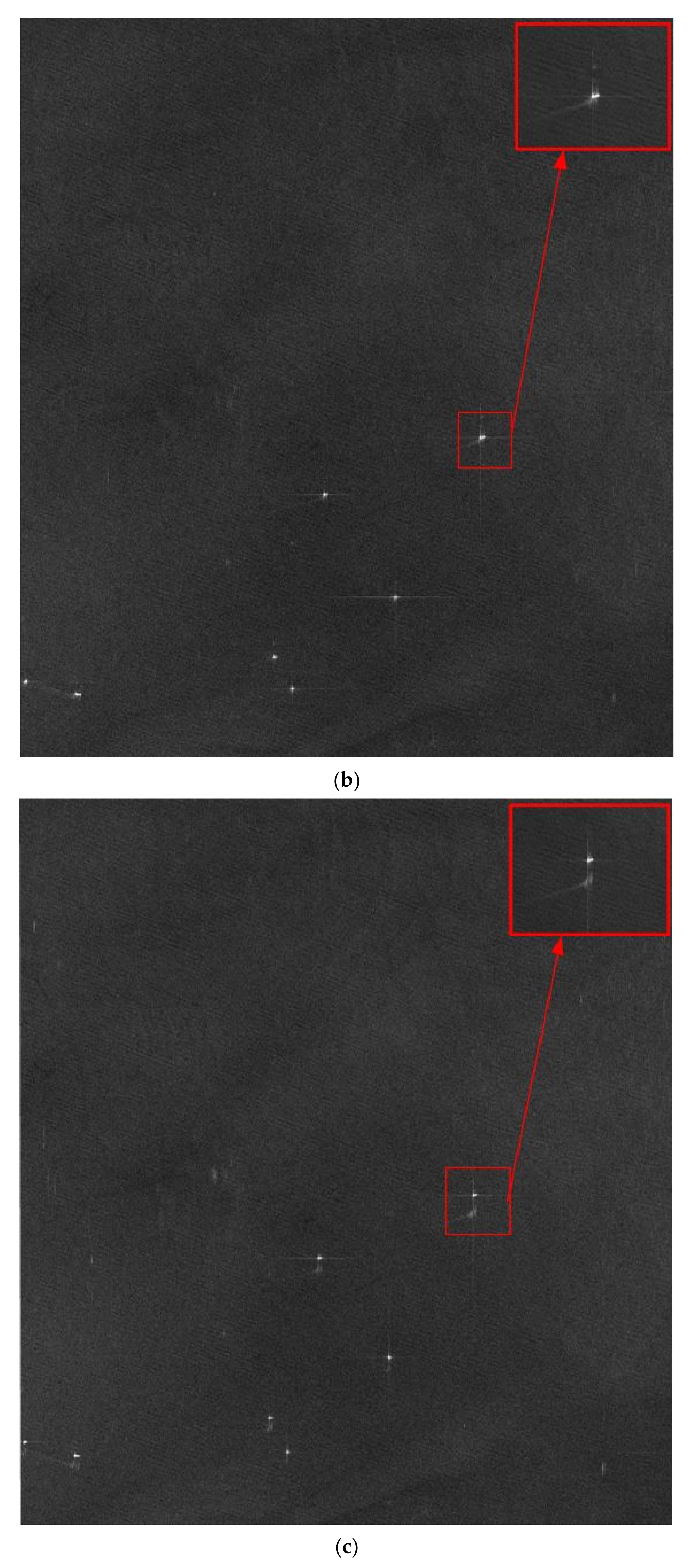
From Figure 5b, method 1 can suppress the false targets and improve the image quality significantly. Besides, it can also realize the relocation of the moving ships after motion phase compensation. The red box shows that the ship coincides with its wake. And Figure 5c illustrated that Method 2 also achieved the effect of false target suppression, but the positions of ships remain unchanged.
5. Conclusions
In order to suppress the azimuth ambiguity of marine moving targets, two motion phase compensation methods are proposed to apply to different practical application conditions. When the phase imbalance between channels is corrected completely and the radial velocity can be estimated accurately, the false targets can be suppressed and the moving target can be relocated by the motion phase compensation in Method 1. Method 2 is suitable for the situation that the phase error between channels cannot be estimated accurately. The combination of the two methods can significantly improve the quality of marine SAR images.
Author Contributions
Conceptualization, J.Y. and X.Q. Methodology, J.Y. and X.Q. Software, J.Y., X.Q., L.Z. and M.S. Investigation, J.Y. Resources, X.Q., L.Z. and M.S. Funding acquisition, X.Q. Supervision, C.D. Writing-original draft preparation, J.Y. Writing-review and editing, X.Q., L.Z., M.S. and C.D. All authors have read and agreed to the published version of the manuscript.
Funding
This research was funded by the National Science Foundation of China under Grant No. 61991421 and No. 61725105.
Conflicts of Interest
The authors declare no conflict of interest.
References
- Freeman, A.; Johnson, W.T.K.; Huneycutt, B.; Jordan, R.; Hensley, S.; Siqueira, P.; Curlander, J. The “Myth” of the minimum SAR antenna area constraint. IEEE Trans. Geosci. Remote Sens. 2000, 38, 320–324. [Google Scholar] [CrossRef] [Green Version]
- Gebert, N.; Almeida, D.; Krieger, G. Airborne Demonstration of Multichannel SAR Imaging. IEEE Geosci Remote Sens. Lett. 2011, 8, 963–967. [Google Scholar] [CrossRef]
- Yang, T.; Li, Z.; Liu, Y.; Bao, Z. Channel error estimation methods for multichannel SAR systems in azimuth. IEEE Geosci Remote Sens. Lett. 2013, 10, 548–552. [Google Scholar] [CrossRef]
- Gebert, N.; Krieger, G.; Moreira, A. Digital beamforming on receive: Techniques and optimization strategies or high-resolution wideswath SAR imaging. IEEE Trans. Aerosp. Electron. Syst. 2009, 45, 564–592. [Google Scholar] [CrossRef] [Green Version]
- Baumgartner, S.V.; Krieger, G. Simultaneous high-resolution wide-swath SAR imaging and ground moving target indication: Processing approaches and system concepts. IEEE J. Sel. Top. Appl. Earth Obs. Remote Sens. 2015, 8, 5015–5029. [Google Scholar] [CrossRef]
- Zhang, S.; Xing, M.; Xia, X.; Guo, R.; Liu, Y.; Bao, Z. A Novel Moving Target Imaging Algorithm for HRWS SAR Based on Local Maximum-Likelihood Minimum Entropy. IEEE Trans. Geosci. Remote Sens. 2014, 52, 5333–5348. [Google Scholar] [CrossRef]
- Yang, T.; Wang, Y.; Li, W. A Moving Target Imaging Algorithm for HRWS SAR/GMTI Systems. IEEE Trans. Aerosp. Electron. Syst. 2017, 53, 1147–1157. [Google Scholar] [CrossRef]
- Jin, T.; Qiu, X.; Hu, D.; Ding, C. Unambiguous imaging of static scenes and moving targets with the first Chinese dual-channel spaceborne SAR sensor. Sensors 2017, 17, 1709. [Google Scholar] [CrossRef] [PubMed] [Green Version]
- Yang, J.; Qiu, X.; Shang, M.; Lv, S.; Zhong, L.; Ding, C. Radial Velocity Estimation of Ships on Open Sea in the Azimuth Multichannel SAR System. IEEE J. Sel. Top. Appl. Earth Obs. Remote Sens. 2021, 14, 3787–3798. [Google Scholar] [CrossRef]
- Yang, J.; Qiu, X.; Zhong, L.; Shang, M.; Ding, C. A Simultaneous Imaging Scheme of Stationary Clutter and Moving Targets for Maritime Scenarios with the First Chinese Dual-Channel Spaceborne SAR Sensor. Remote Sens. 2019, 11, 2275. [Google Scholar] [CrossRef] [Green Version]
- Cumming, I.; Dettwiler, M.; Wong, F. Digital Signal Processing of Synthetic Aperture Radar Data: Algorithms and Implementation; Artech House: Norwood, MA, USA, 2004. [Google Scholar]
- Shang, M.; Qiu, X.; Han, B.; Ding, C.; Hu, Y. Channel imbalances and along-track baseline estimation for the GF-3 azimuth multichannel mode. Remote Sens. 2019, 11, 1297. [Google Scholar] [CrossRef] [Green Version]
Figure 1.
Imaging geometry of HRWS SAR system.

Figure 2.
The relationship between the azimuth time of each channel and that of the reconstructed equivalent single-channel.
Figure 2.
The relationship between the azimuth time of each channel and that of the reconstructed equivalent single-channel.

Figure 3.
Simulation imaging results. There is no phase imbalance between channels: (a–c); There is residual phase error between channels: (d–f).
Figure 3.
Simulation imaging results. There is no phase imbalance between channels: (a–c); There is residual phase error between channels: (d–f).


Figure 4.
The omitted phase terms in (16) of each channel for the simulated azimuth four-channel SAR system.
Figure 4.
The omitted phase terms in (16) of each channel for the simulated azimuth four-channel SAR system.

Figure 5.
Imaging result of GF-3 UFS mode: (a) Before motion phase compensation; (b) After motion phase compensation by Method 1; (c) After motion phase compensation by Method 2.
Figure 5.
Imaging result of GF-3 UFS mode: (a) Before motion phase compensation; (b) After motion phase compensation by Method 1; (c) After motion phase compensation by Method 2.


Table 1.
The radial velocity of the seven ships in Figure 5a.
Table 1.
The radial velocity of the seven ships in Figure 5a.
| Radial Velocity | SCR (Range Compression Domain) | |
|---|---|---|
| Ship 1 | 3.28 m/s | 18.25 dB |
| Ship 2 | 2.89 m/s | 17.03 dB |
| Ship 3 | 3.40 m/s | 24.45 dB |
| Ship 4 | 2.46 m/s | 24.07 dB |
| Ship 5 | 3.38 m/s | 17.11 dB |
| Ship 6 | 4.12 m/s | 21.65 dB |
| Ship 7 | 5.98 m/s | 20.87 dB |
Publisher’s Note: MDPI stays neutral with regard to jurisdictional claims in published maps and institutional affiliations. |
© 2021 by the authors. Licensee MDPI, Basel, Switzerland. This article is an open access article distributed under the terms and conditions of the Creative Commons Attribution (CC BY) license (https://creativecommons.org/licenses/by/4.0/).
Share and Cite
MDPI and ACS Style
Yang, J.; Qiu, X.; Shang, M.; Zhong, L.; Ding, C. Motion Phase Compensation Methods for Azimuth Ambiguity Suppression in HRWS SAR. Remote Sens. 2021, 13, 3543. https://0-doi-org.brum.beds.ac.uk/10.3390/rs13173543
AMA Style
Yang J, Qiu X, Shang M, Zhong L, Ding C. Motion Phase Compensation Methods for Azimuth Ambiguity Suppression in HRWS SAR. Remote Sensing. 2021; 13(17):3543. https://0-doi-org.brum.beds.ac.uk/10.3390/rs13173543
Chicago/Turabian StyleYang, Junying, Xiaolan Qiu, Mingyang Shang, Lihua Zhong, and Chibiao Ding. 2021. "Motion Phase Compensation Methods for Azimuth Ambiguity Suppression in HRWS SAR" Remote Sensing 13, no. 17: 3543. https://0-doi-org.brum.beds.ac.uk/10.3390/rs13173543
Note that from the first issue of 2016, this journal uses article numbers instead of page numbers. See further details here.