
Towards a Multimodal Representation: Claudia Octavia’s Bequeathal


1
Department of Engineering, Università Degli Studi Della Campania Luigi Vanvitelli, Via Roma 29, 81031 Aversa, Italy
2
Escuela Técnica Superior de Arquitectura, Universitat Politècnica de València, Camino de Vera, 46022 Valencia, Spain
*
Author to whom correspondence should be addressed.
Remote Sens. 2022, 14(2), 429; https://0-doi-org.brum.beds.ac.uk/10.3390/rs14020429
Submission received: 29 November 2021
/
Revised: 5 January 2022
/
Accepted: 13 January 2022
/
Published: 17 January 2022
(This article belongs to the Special Issue 3D Virtual Reconstruction for Cultural Heritage)
Abstract
:Through a non-contact survey methodology, based on image-based techniques, the authors digitally ‘build’ a three-dimensional hypothesis of a monumental complex carved on a first-century AC marble tombstone. Guided by the mathematical rationality recognised in the artefact, the paper illustrates the reasons for the reconstructive choices and then proposes a reflection on the architectural contents. The ultimate goal focuses on the potential use of the digital product, which, thanks to and by virtue of the use of dedicated platforms, promotes strategies that include identity values by superimposing technical, social, and economic aspects. The setting up of collaborative spaces programmed with different strategies can effectively support the cognitive experience by verifying the possibility of “remedying” contents that, in our case, direct the study, dissemination, and protection of cultural heritage according to the most recent UNESCO recommendations.
1. Introduction
The 3D reconstruction of an artefact in its entirety aims at reconstructing its hypothetical original aspect; hence, the main problem refers to its authenticity and can be overcome with rigorous philological methods. This permits us to rebuild virtually a building adding the missing parts not through invention but basing them on concepts and comparisons that make them reliable [1]. In the literature, these 3D models have been called different things, such as simulative models [2], visualisations [3], and 3D approximations [4], in order to underline the fictional character of their realisation and to highlight the interpretations that led to the reconstruction. The procedure is not immune to problems regarding trustworthiness and scientific accuracy, mostly because usually it reconstructs structures from little information or a few details, starting from remains. On the other hand, these models can be of great value not only for the visualisation and hence dissemination of Cultural Heritage to non-experts, in order to simplify the understanding of the artefact, but also for study and documentation, since they can be the basis for different hypotheses, allowing for a better understanding of complex information. This process can be done using Computer-Aided Design software, such as 3D Studio Max or Rhinoceros, but considering the added value that the external information can give to the comprehension of the reconstruction, BIM software seems to be the best choice.
Since the term ‘Building Information Modelling’ (BIM) describes the process of creating and managing a digital model containing information of different types (structural, energy, geometric, plant engineering, etc.) on a building, whether it is in the design/construction phase or already existing, a specific tool for managing all the information, which can be used by all the actors involved, is required. It is precisely for this reason that the need arises to have a data sharing environment. In many countries, this environment is a Common Data Environment (CDE) as defined by the British PAS 1192 standards and is adopted to allow for the best use of the interoperability of BIM. In the passage from analogic to digital culture, the communication system is also changed. The CDE is a single digital environment for sharing all the information content needed for the management of a property within its life cycle. The CDE is therefore the tool used to collect, manage, and exchange the model, the non-graphic data, and all the documentation (i.e., the set of all pieces of information on the project created in a BIM environment) between all the members of the project team, facilitating their collaboration and helping them to avoid duplication and errors. The identification of the authorship of each piece of information within the CDE is essential. The individual models produced by different members of the project team thus have a clear authorship and remain separate, while contributing, each with its own specialisation, to the realisation of the overall model [5,6,7]. The integration of information relating to the model can be implemented through the use of CDEs, which allow for different types of documentation organised by specific directories to be stored in a shared cloud, from which it will be possible to manage access depending on the roles covered.
For the preservation of Cultural Heritage, it is mandatory to find a way to take care of its redevelopment over time. Hence HBIM, or the need to use digitalisation by applying BIM to historic buildings, which, by their very nature, are often the result of layering of evolutionary phases, materials, and architectural changes over the years. All this information is difficult to assimilate through traditional management, which denotes a high risk of loss of important data necessary to the subsequent intervention phases. Furthermore, the entities that manage the historical-artistic heritage are usually multiple and different from each other, often leading to the fragmentation of information. Therefore, every time an intervention has to be planned on an existing historic building, most of the initial time is spent on researching and organising information and data. Historical or Heritage Building Information Modelling is the process applied to existing buildings or monuments that aims not only at the mere restitution of the three-dimensional model, but above all at the creation of so-called “intelligent models”. The latter are rich in geometric information and include the state of conservation of the materials, in which all components are parametric objects with well-defined semantics and capable of containing all the historical information derived from appropriate documentary analyses [8]. The objective of the HBIM process, therefore, is to generate an information model that is congruent and geometrically consistent with reality, where most of the information collected up to that moment is contained, as if it were a digital “catalogue” that can be interrogated in case of necessity [9]. The steps in the HBIM process can be summarised as follows:
- Acquisition of the historical-construction information on the artifact.
The correct approach to HBIM involves searching for all available paper and digital documentation, historical and recent, available from state archives, local authorities, libraries, and any archive that may have information relating to the construction. This action represents the first step in the correct application of the process, with a view to recovery and restoration consistent with the history of the building.
- b.
- Survey.
As the basis of the modelling for the graphical rendering, a survey through laser scanning or photogrammetry must necessarily take place.
- c.
- Creation of the model.
The next step is to create the model. By creating specific libraries of parametric objects, the information content is enriched to compose the complete BIM of the product. In fact, from a three-dimensional surface that originates from the surveyed work, it is necessary to create a parametric BIM. Considering then that the existing buildings hardly ever-present characteristics of regularity and repetitiveness, the modelling of these artifacts becomes a rather complex operation with a considerable waste of time and resources.
- d.
- Population of documentary information within the model.
The HBIM can be considered complete only when the correlations are in place within the multiple masses of data that allow the user to interrogate the model from the historical document point of view. Furthermore, the possibility of integrating the information within the model over time is of fundamental importance, will be reflected throughout the life of the building, and will allow us to keep track of any intervention or integration over the years.
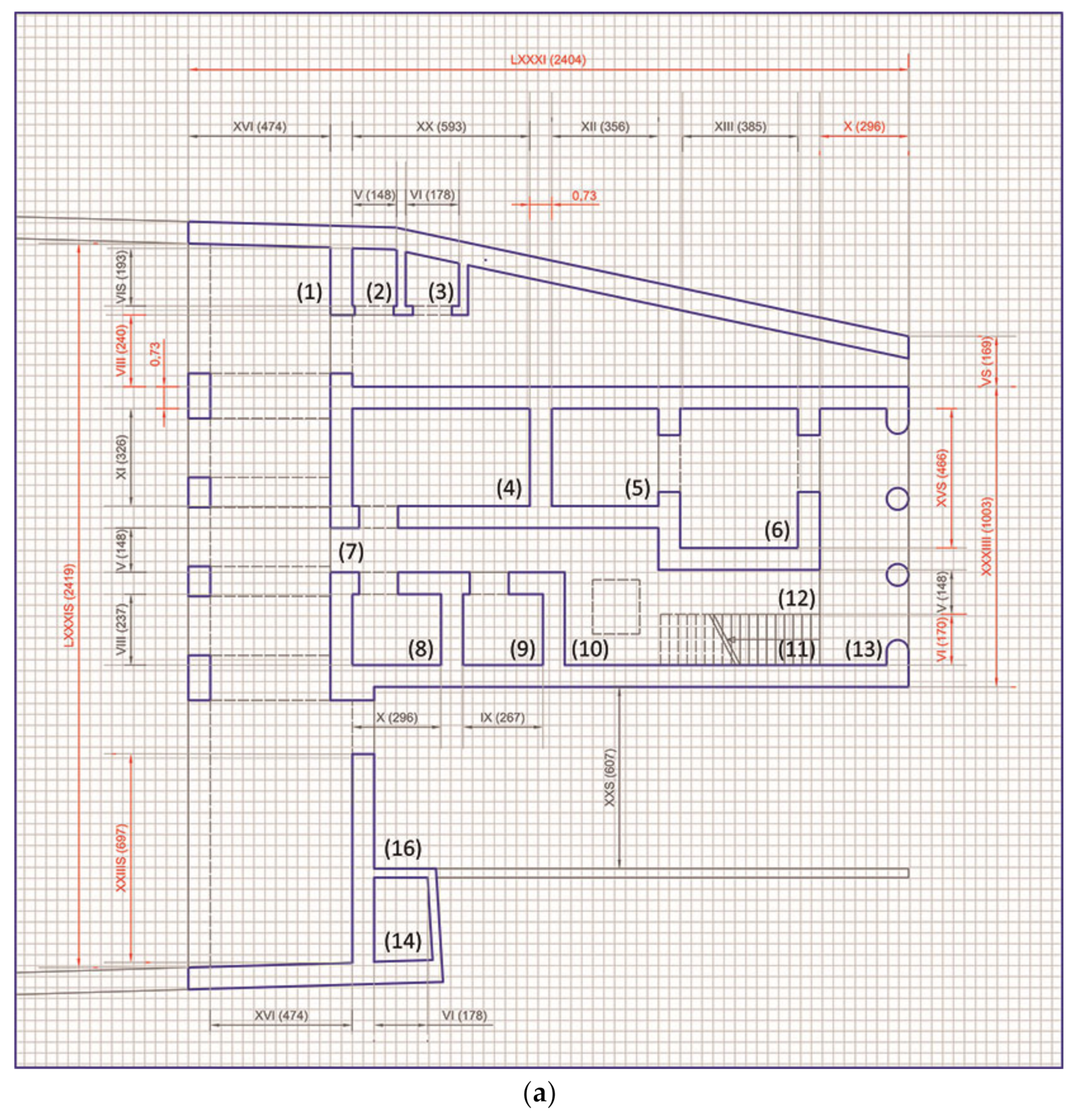
This article proposes a potential reflection on the architectural contents of the documented heritage, explaining the passage that leads from the interpretation of the iconographies to the design control of the scheme of virtual reconstructions. The discussion uses modelling and digitisation as keys to the analysis of attributes and properties, thus expressing the design complexity of a self-sufficient virtual environment in dynamic equilibrium.
The three-dimensional reconstruction of the legacy in favour of Claudia Peloris, liberta of Claudia Ottavia, is in fact an opportunity to reflect on the methods that carry the massive collection of data towards a digital ecosystem that uses a dedicated platform to convey the interests of the audience to the broader shared cultural vision. This vision is intended as a place of social and economic profit as well as a technical and useful cultural one to advance both our knowledge of the processes of documentation of the asset and the strategies suitable for protecting and enhancing them.
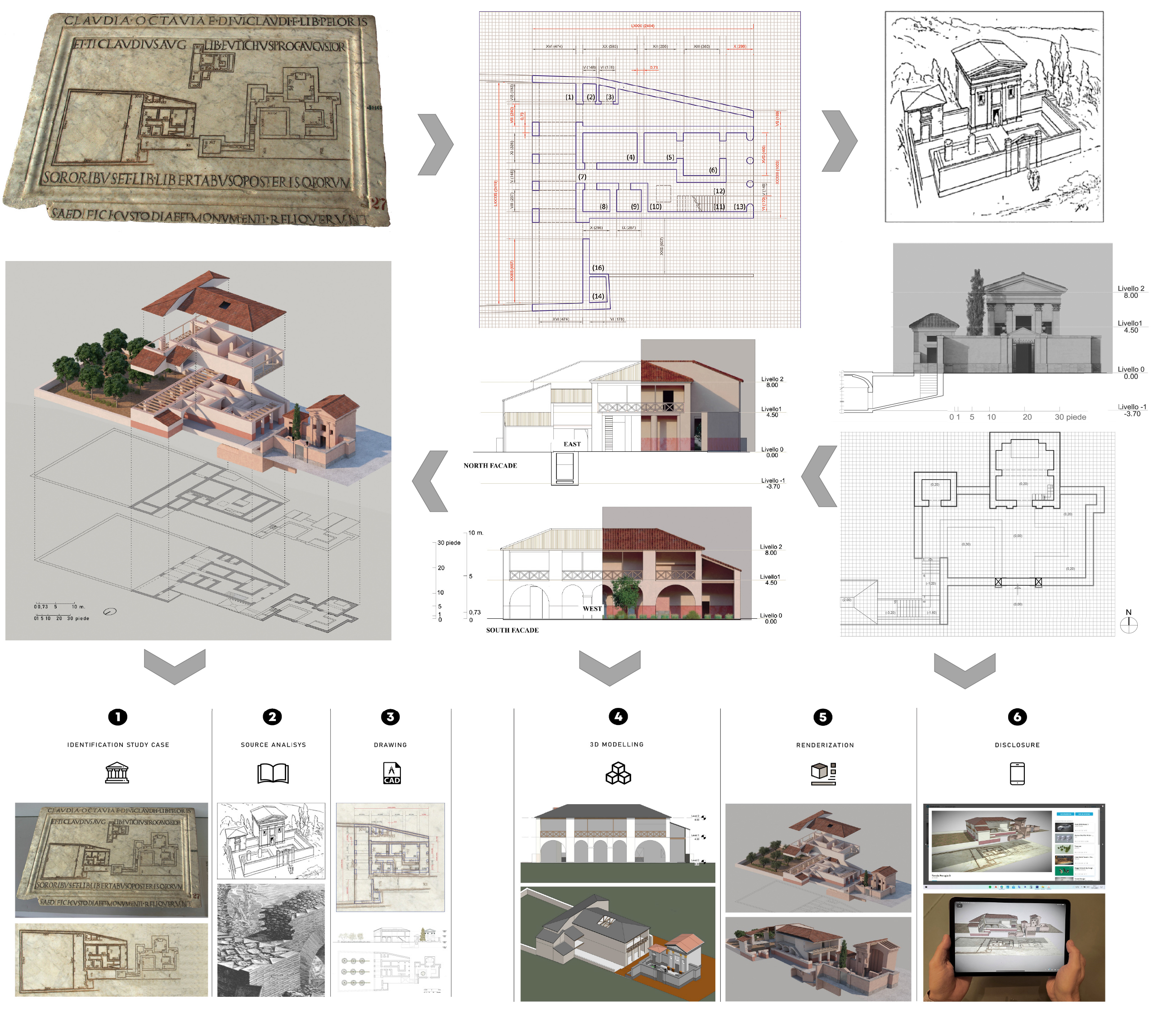
The artefact analysed in this paper (Figure 1) is now preserved in the Archaeological Museum of Perugia (Museo Archologico Nazionale di Perugia, n. 225 “Pianta marmorea con iscrizione funeraria di liberti di Ottavia e di Nerone” Marmo 54–68 dC. Coll. Gaddi Coll. Oddi, Inv. Com. 486. Rep. No. 45555555555) [10] (p. 63) and comes from Rome’s “Bastioni del Belvedere” (1544–1548). It is a rectangular, marble slab approximately 580 × 820 mm in size, conserved in excellent condition, and only missing a small portion in the lower left corner.
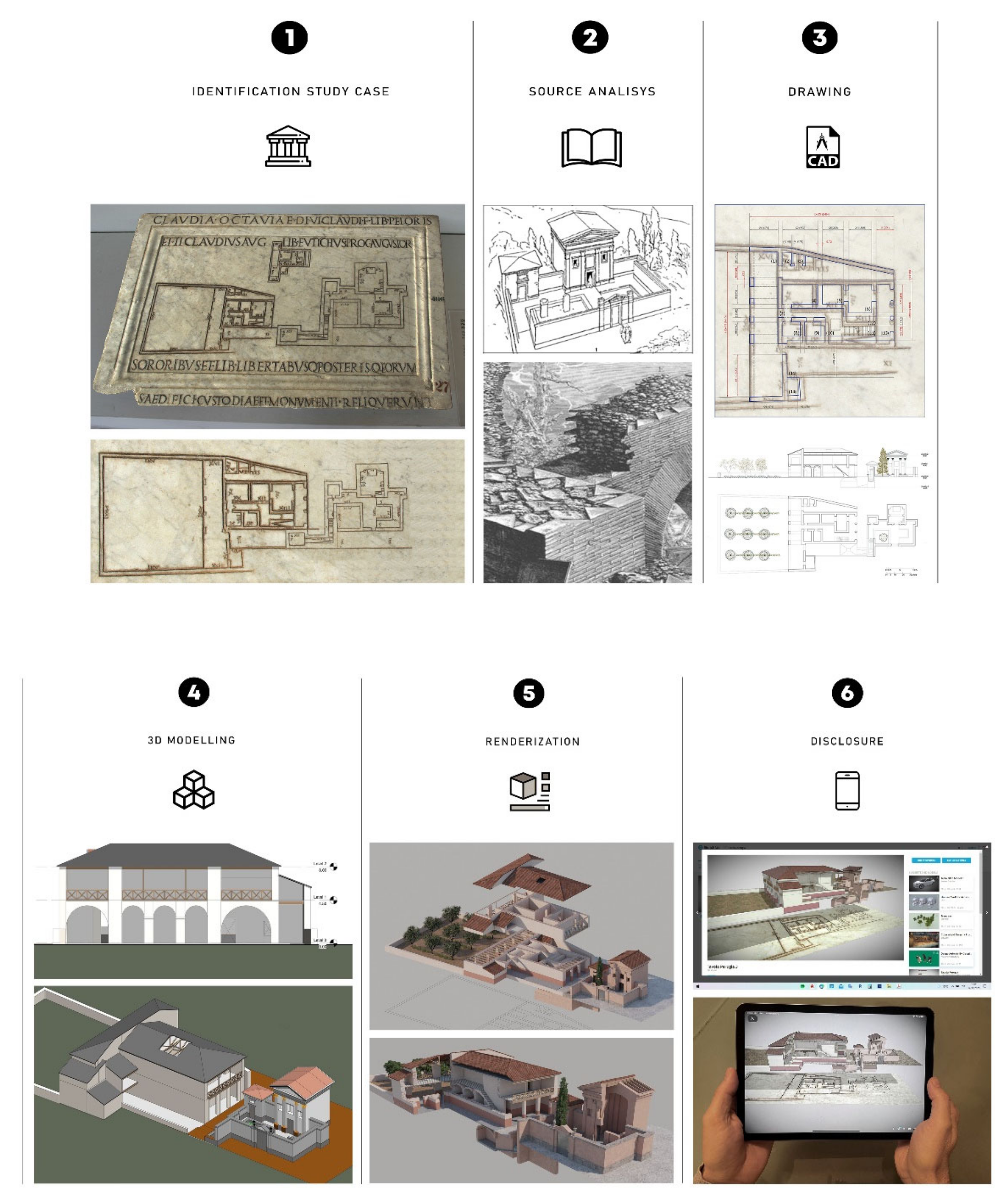
This paper presents the processing from a 3D reality-based acquisition of the slab in order to obtain an orthophoto on which accurate measurements can be taken for the following steps. The floor plan developed in CAD software was imported into Autodesk’s Bim Outoring Revit software, which supports the construction industry, fuelling new production and prefabrication channels in the design and management phases.
Proceeding with the extraction of the geometries of the classified components by analysing the three iconographies of the slab, an initial information model was developed referring to both the geometric characteristics (LOD—detail) and the informative ones (LOI—information). As this is a first-century building, no family archives useful for digital construction have been found to date. However, it is possible to proceed correctly if it is remembered that “without exclusion of priorities and according to specific needs, the specific references, logic, objectives, and structure of use of the LOD-LOI are clearly stated” [UNI: 11337-4 2017]. In line with the Italian standard (https://www.ingenio-web.it/18667-sistema-dei-lod-italiano-uni-11337-4-2017, accessed on 28 November 2021) that, in order to distinguish more clearly between Development, Definition, and Detail, identifies a new “qualitative–quantitative development level referred to as the geometric shape” (LOG), which is believed to be able to configure a corresponding model (LOG 3D). Geometric virtualisations can be visited taking advantage of the free service made available by Sketchfab defined with a type C level of detail of the general scale of LODs [11] (LOD A, symbolic object; LOD B, generic object; LOD C, defined object; LOD D, detailed subject; LOD E, specific object; LOD F, executed object; LOD G, updated object). The work started from a 3D survey with photogrammetry of the marble slab to obtain an orthophoto to be used as a basis for the subsequent steps. Even if the plan engraved in the slab is not perfectly dimensioned (the first floor is evidently smaller compared with the lower one), the measurements of each wall helped in understanding the real dimensions of the complex. On the other hand, they helped the interpretation of the process followed in reducing the plan of each building because of the small amount of space available on the slab. The following step in the analysis of the ancient complex considered the measurements and the geometry indicated in the slab for a rational 3D reconstruction of the complex as it should have been in antiquity. The possibility to use not only the drawing of the plans of the two floors of the house and the temple but also the measurements helped in creating a more plausible reconstruction. Archival documents and a comparison with other similar monuments still visible today gave a more accurate idea of the structure of the building. The reasons for and the path that led to the digital reconstruction of the architectural complex [12] were applied in compliance with the guidelines disclosed in the “Document on Authenticity” [13] and the subsequent declarations on the Safeguarding of Intangible Cultural Heritage [14].
2. Materials and Methods
The engravings of the slab of Perugia represent a sepulchral temple on the right of the slab, to the left of which is engraved the plan of the ground floor of a rustic villa with a vegetable garden behind it, while in a heliocentric position, considerably reduced, is a plan of the mezzanine floor, the hypothetical residence of the keeper. The epigraph is visibly engraved on two lines on the top and on the bottom of the slab, with a flat strip dividing them as a kind of frame. The caption reads:
Claudia Peloris, freedwoman of Octavia, daughter of the divine Claudius and Tiberius Claudius Eutychus freedman of Augustus, procurator Augustus, left the plan of the sepulchral monument and the custody building to the sisters and their freedmen and freedwoman and posterity (Claudia, Octaviae divi Claudi f(iliae) lib(erta) Peloris/et Ti(berius) Claudius Aug(usti) lib(ertus) Eutychus, proc(urator) Augustor(um), /sororibus et lib(ertis) libertabusq(ue) posterisq(ue) eorum//formas aedifici custodiae et monumenti reliquerunt).
The inscription clarifies that it consists of a bequest to Claudia Peloris, freedwoman of Claudia Octavia, daughter of the Emperor Claudio and of his third wife Valeria Messalina. The date of birth of princess Octavia is probably 40–42 AC, while the date of death, on the contrary, was uniquely determined by Publius Cornelius Tacitus [15], who reports that in June 62 AC the head of the twenty-two-year-old Octavia, abhorred by her husband, the emperor Nero, who forced her into exile where she was assassinated the following year [16], was brought to Rome to be shown to Sabina Poppea who, in the same year, became the wife of the emperor Nero. The engraving of the table therefore falls between the death of Claudius, poisoned in 54 AC, and the death of Octavia (according to Tacitus, she would have died at the age of twenty in 62 AC, and therefore would have been born in 42–43. According to Cassio Dione, she would have come to light in 41, while for contemporary scholars she would have been born before 40 AC "when Claudius had so little importance in the imperial family that the birth of the child was not news worthy of mention”).
While the dating of the slab falls between 54 and 62 AC and is, therefore, certain, the origin is not [17]. For some scholars, the slab was inserted into the base of the mausoleum represented on it [18] (pp. 31–34); for others, the priority is to ascertain where the monumental complex was located, since it is not certain or obvious that it was located in Rome or its surroundings. As a matter of fact, this information is not important for the investigation described in this paper, which aims at reconstructing the monumental complex starting from the plans and especially the dimensions indicated along each wall engraved. Due to its shape, material, and conservation, it is suitable to be studied and investigated without contact survey techniques.
Marco Vitruvius Pollio described in the first twenty years of the first century AC some ways (species dispositionis) through which to reason on the appearance of artefacts (adumbrationes). About Ichnographia (the plant) in particular, Vitruvius explains how the footprint of the building is used to perform measurement operations [18]. In the plans on the slab of Perugia, engraved a few decades later, the dimensions, calculated in the anthropometric units used at the time and proportionally reported, quantify the lengths of the walls.
A few erudite texts select the three engravings as emblems of the mathematical rationality of which the Romans of the first century AC were capable of. The first to make a detailed examination of the find was the German philologist Heinrich Jordan [19], who in 1878 emphasised the originality, the merits, and the limits of the graphic signs engraved on the plate. The unit of measurement is the “foot” (Pes in Latin), defined as 16/28ths of the cubit of Nippur (the theoretical value of Nippur’s cubit is exactly 518,616 μm; consequently, the Roman foot is 296,352 µm ≤ 29.64 cm. Under Severus and Diocletian, the foot had undergone a slight shortening, so as to make its attribute no more than 0.29421 m, equivalent to 29.64 cm [20] (p. 238). In late antiquity, the foot was divided into twelve parts (uncia); before the medieval period, however, it was subdivided into sixteen parts, or digitus [21] (p. 354), corresponding, in the current international system, to 0.29574 m [19]. The “S” with which some Roman numerals end, the symbol of “Span” (half a cubit, 9 inches, or 22.86 cm) or “Semis” (half a foot, about 15 cm), confirms the juridic nature (formas…reliquerunt) of the document [17] (p. 37), undoubtedly of importance to the degree of centesimal approximation of the measures and of no sense if the plan were a project drawing.
The pipeline for an accurate 3D reconstruction starts from the analysis of the material available. In this case, no physical remains are visible; hence, the study of the plans engraved on the marble were fundamental, not only to the drawing but also the measurements indicated for almost every wall. In this way, it was possible to unify the graphical and geometrical aspects with the numerical ones in order to achieve the best solution to the 3D modelling.
2.1. Analysis of the Engravings
Guglielmo Gatti calculated the reduction scale of 1:83 for the monumental temple, almost doubled for the ground floor of the rustic villa served by the back garden and sculpted on a scale of 1:140 and tripled for the caretaker’s housing reported on a scale of 1:230, by comparing the geometric configurations and the real measurements [22] (p. 33). The differences in the scalar ratios are applied to the symbolic importance of the artefacts rather than to the level of detail or development of the building. Some perplexities, however, are raised by the position of the smallest of the plans, which is clumsily wedged against the upper epigraph as if it were unexpected or added.
The photogrammetric survey served as a basis for the hypothetical reconstruction of the monuments, giving metric information on which the mathematical calculation of the proportions started. Considering the anomalies in the dimensions of the three plans, the orthophoto created from the 3D photogrammetric model helped in identifying the correct proportions of the real buildings. This metric information, integrated into the information gained through the analysis of the engravings and previous studies, allowed us to accurately reconstruct the buildings, taking into consideration the geometrical and architectonical proportion of the shapes.
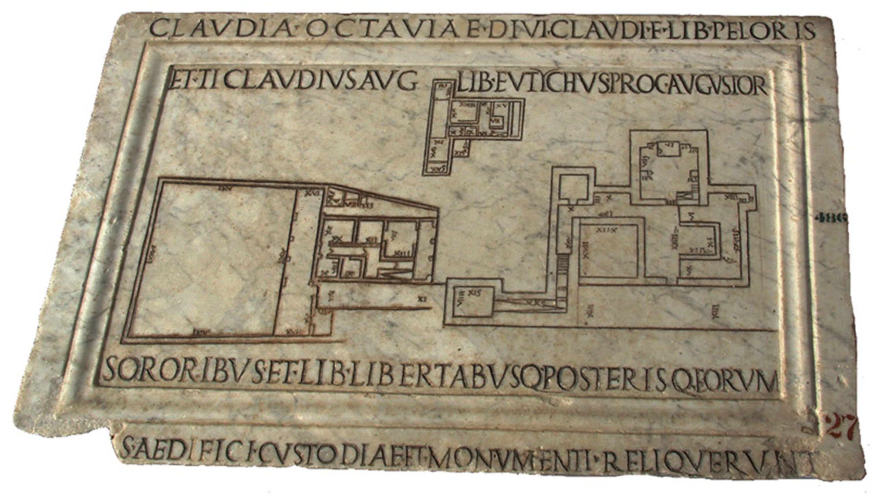
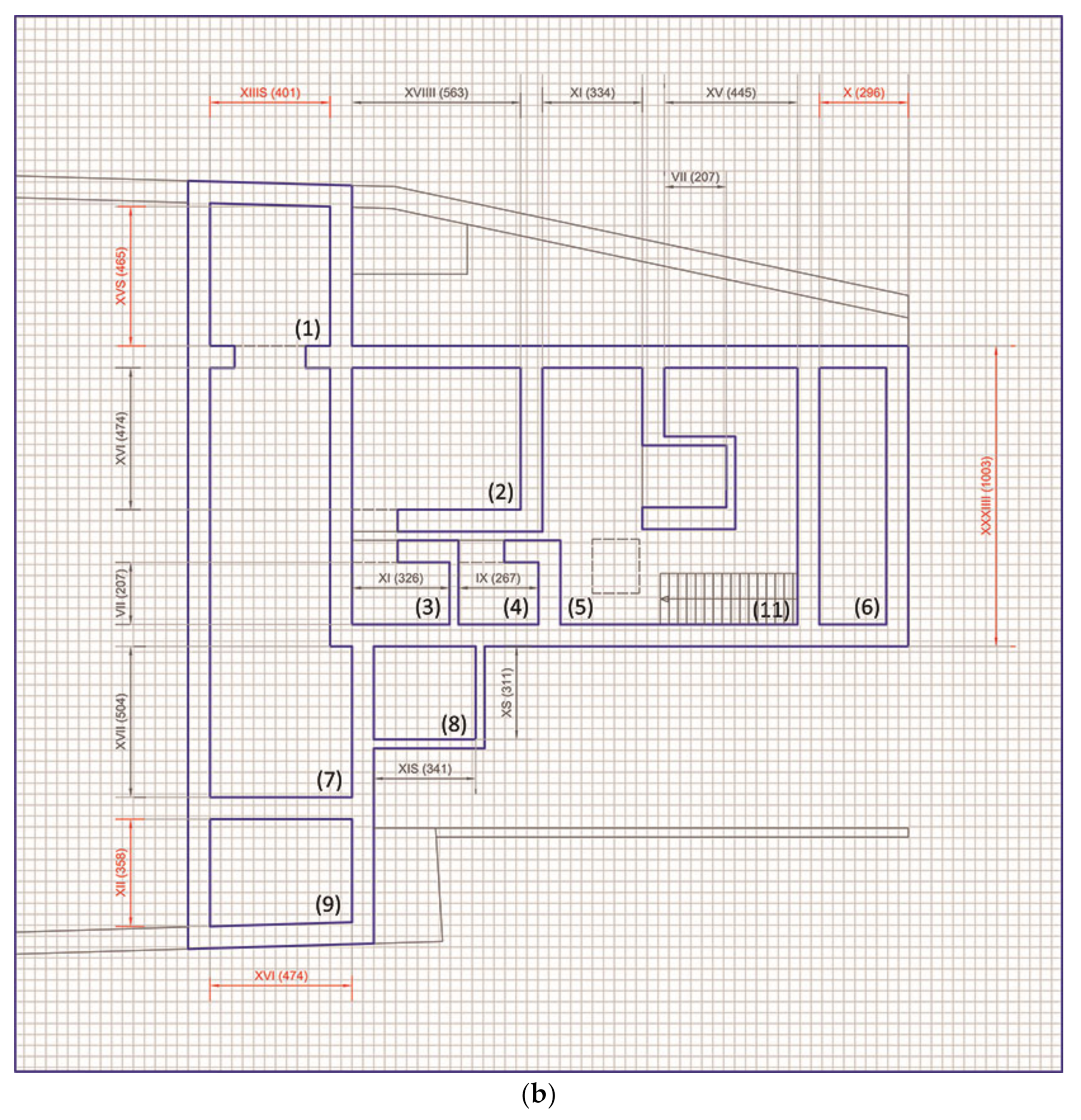
The anomalies have been noted accordingly (Figure 2) on a grid of commensuration of the parts derived from the thickness of the wall. All the measurements were then used to draw a plan of the first floor and the upper floors, which was then compared to the engravings on the slab metrically derived from the orthophoto in order to identify the differences.
The survey was carried out using a Canon 60D camera with a 20 mm fixed lens. Three shots were enough to obtain a 3D metric model (to be more precise, a 2.5D model). The distance from which the images were taken was about 1 m and, due to the light conditions of the museum, a tripod was used that permitted us to set the ISO at 200 and the aperture at 11, which provided the required accuracy. The Depth of Field was 1.314 m and the Ground Sampling Distance was 0.2 mm. The orthophoto was created using Agisoft Metashape, scaling the 3D model with the proprietary target placed all around the slab, and automatically detected by the software. To refine the scaling, two metallic scalebars were positioned, one horizontal and one vertical, near the artefact. In this way, out of the six scalebars, the four that gave the lowest error were used to scale the model. After extracting the orthophoto and digitising the building plan, the subsequent analysis superimposed and integrated plans of material, textual, and iconographic information.
2.2. Distribution and Functionality of the Environments
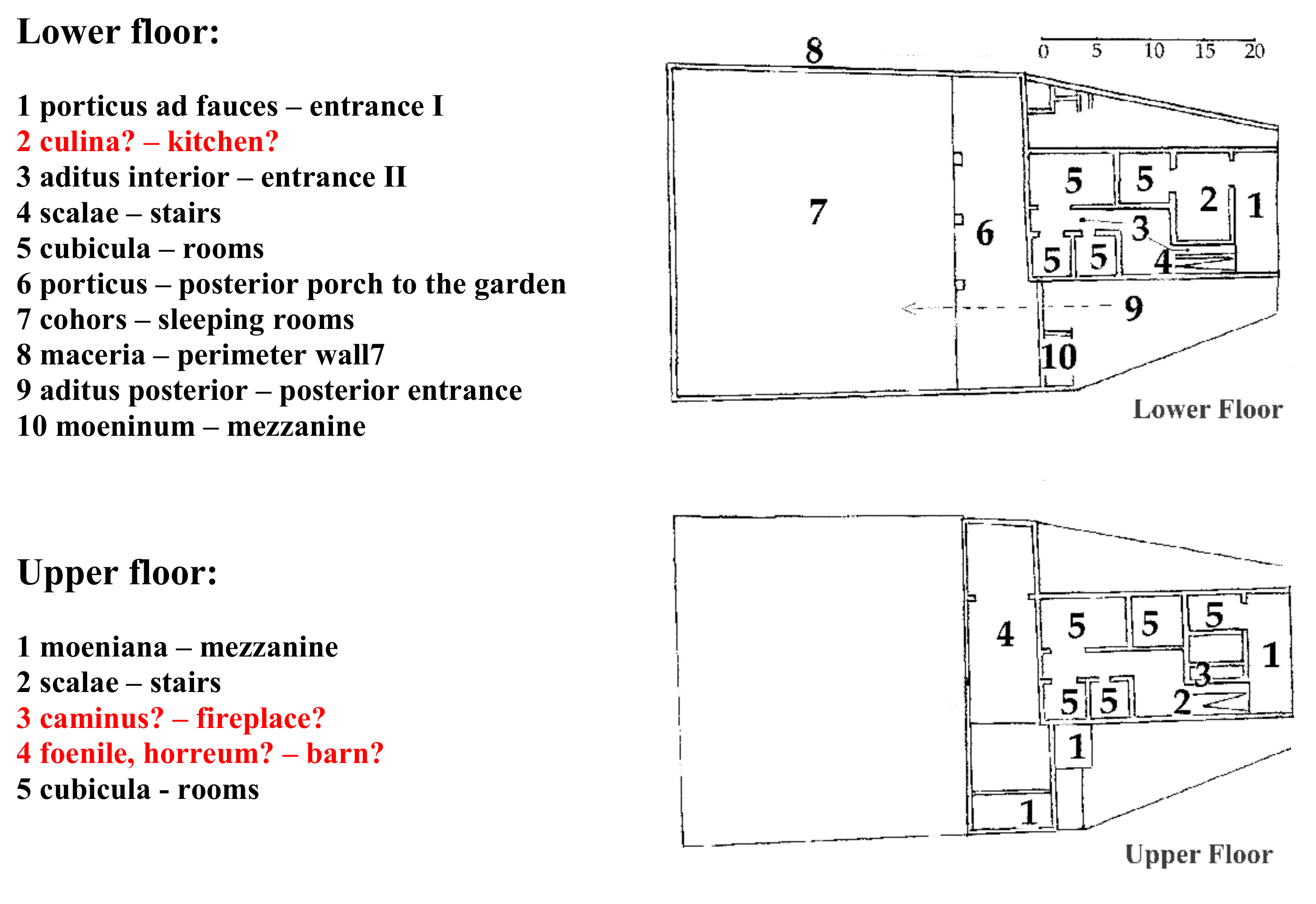
The most interesting and amazing thing is that the precision of the conventions and symbols seems to be practically unchanged after two millennia. The graphical description of the walls, for example, is defined by two parallel lines cut nearby the sectioned light compartments. According to the recommendations of Vitruvius, the temple was most likely positioned taking into consideration the apparent path of the stars [23], while it is possible that the positioning of the monumental building was carried out on a trigonometric and, perhaps, astronomical-projective basis [24]. As far as the distribution of the rooms of the aedificium custodiae is concerned, where functional needs are more urgent, the microclimatic needs imposed by the habitability were certainly taken into account, considering that usually the buildings had no windows [18]. The rooms of the villa are distributed around the path connecting the anterior and the posterior porch and in the middle is visible the vertical connection for the first floor. The stairs are marked, as still happens today, with a very long and acute angular sign, a sort of “V”, as in the access corridor to the underground cubicle adjacent to the temple. Considering the hypothesis regarding the internal distribution of the rooms as found in the literature (Figure 3), it is fundamental to identify the specific signs that univocally depict the features according to methodologically repeatable procedures. This process makes them criticisable in any place and time.
As highlighted in the text by Emilio Rodriquez Almeida [17] (Figure 13, Chapter IV), it should be remembered that the Romans did not know about fireplaces, which appeared in Italy only around the 13th century [25] (p. 191). The term Atrium itself derives from “ater”, which means ‘dark’ or ‘black’, due to the black soot that covered the walls in the place where originally wood was burned to cook or smoke food and, subsequently, water was collected. The smoke mainly found its way out in the natural draft derived from the hole in the roof, an extreme legacy of the one made on the top of pre and protohistoric huts. From this necessity derives the opening for light and air close to the kitchen that also provided the necessary light to the staircase connecting the side of the rustic villa to the rear and front porch.
2.3. Technical Problems for Reconstruction
All the data gained from the dimensions of the engravings derived from the orthophoto and the number on the slab permitted us to hypothesise with high accuracy about the geometry and proportions of the different rooms, their exact location in the plan, and their use based on a comparison with still-preserved villae. On the other hand, no information on the elevations is given by the engravings and this makes it more difficult to understand the building, because the vertical information is what usually allows non-expert to understand more about not only the subdivision of the plan but also the specific purpose of each room [26]. Ignoring the size of the risers or the slopes of the ramps, an estimation derived from the mathematical dimensioning of the plant was done in detail and vectorised on the same metric scale, adopting an average value derived from a comparison of the reported and calculated quotas shown in Table 1.
2.4. Reconstruction Hypothesis
The first step in transcribing quantities calculated in geometrical qualities is the verification of how many times a sample unit is contained in the lengths to be described. The material extension of architecture, however, is not only and exclusively measured through the geometries and arithmetic relationships. The history of the technique, of the culture, and of the place is also needed along with the programmatic outcomes. Hence, the interpretative process of the 3D form lies in a comparison with coeval ruins with similar planning. Among the textual evidence, the most reliable is the aforementioned De Architettura by Vitruvius, made public about fifty years before the execution of the slab of Perugia.
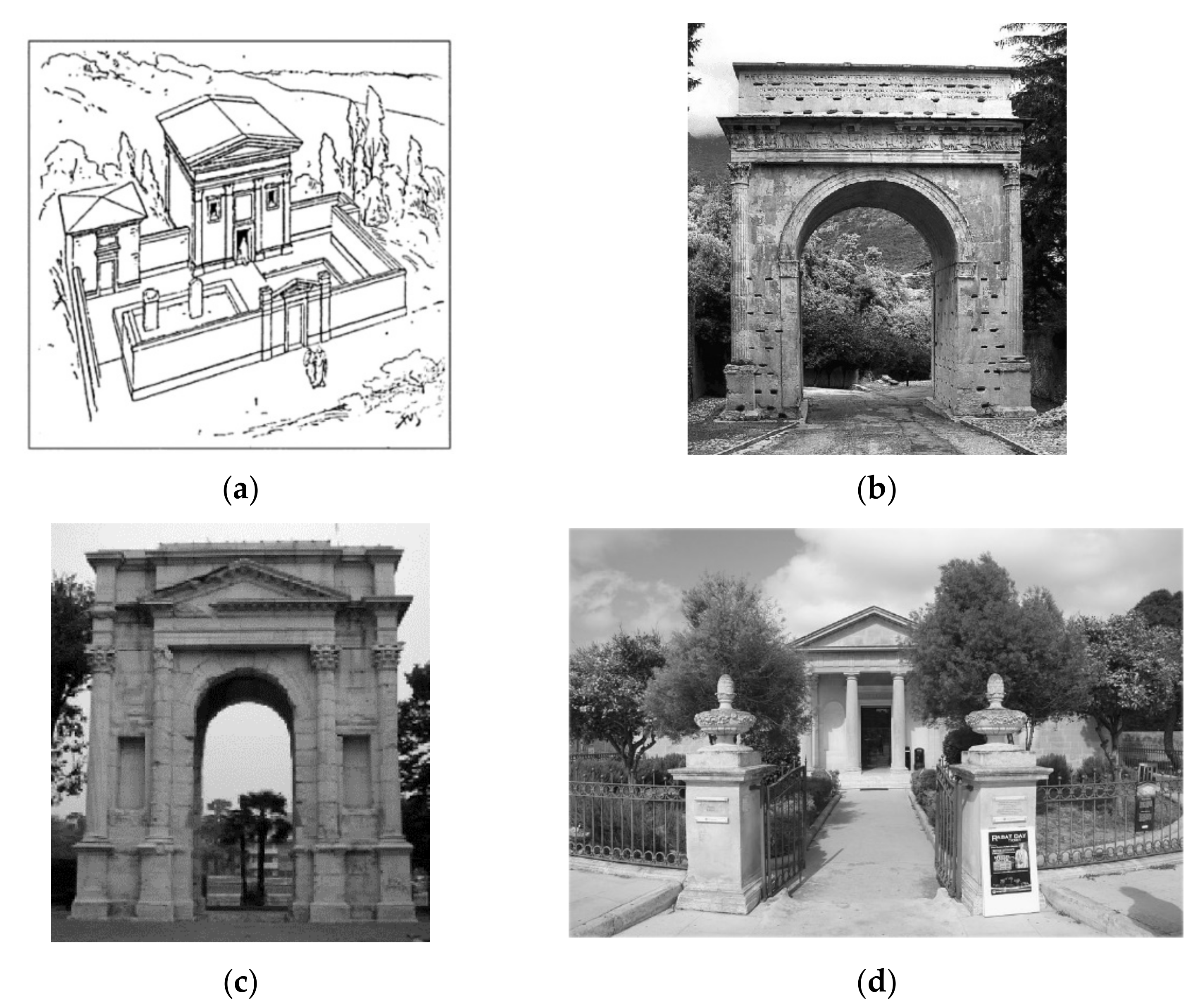
For this purpose, the studies of nineteenth-century archaeologists also served as a typological reference. The axonometric sketch (Figure 5a) of the monumental building reconstructed on the façade was made by Christian Carl Friedrich Hülsen [29] (p. 53). The expert in classical and medieval tradition hypothesised about its appearance, replicating the style of the triumphal arches built by the imperial families of the Augustan and Julio-Claudian ages. The Arc of Susa (Figure 5b), built in 9–8 BC, was used as a reference alongside the arch of Gavi (Figure 5c), which was built in the second half of the first century AC along the Via Postumia in Verona and is a rare case of a monumental arch intended for private individuals. More frequently, the mausoleums were inspired by the Arc de Triomphe in Orange from the first century AC and by the architecture of ancient Greece erected with memorial-funerary values [30]. The monumental building with a hypogeum environment accessible by a ramp (Figure 5d), rebuilt around the archaeological findings of the first century AC, that came to light by chance in 1881 when planting the Park of Rabat, today an important and rich museum of the Domus Romana of the island of Malta (https://Malta.italiani.it/domus-romana/, accessed on 27 November 2021), was the main basis for the reconstruction of the buildings shown on the slab of Perugia.
The collected documentation makes the geometric reconstruction of the mortuary temple plausible. The morphological reconstruction of the rustic villa appears to be much more arbitrary. However, the transparency of the sources allows us to evaluate the historical reliability of the interpretations and reconstructions. Additionally, for this reason it was considered appropriate to transcribe the representations into digital re-fabrications [31] (pp. 179–184). At the basis of the adopted practice is the objective data obtained from the analysis of the finds. The iconographies were studied in detail, vectorised by adopting an average value obtained by comparing the dimensions calculated with the geometry of the engravings, and are reported in metric scale in Figure 6.
The transformation of the shapes into effective components [32] presupposes the segmentation of the parts and the definition of the information and development levels of the system components extracted hierarchically. In this case, they were divided into: (a) vertical wall structures; (b) horizontal floor structures; and (c) roof structures.
2.4.1. Vertical Structures
The load-bearing masonry structure has an average thickness of 72–74 cm (2.5 Roman feet) and was built by using a double row of bricks into which the concrete was cast [33]. In the first century, after the standardisation of the brick, they were supplied with improved cuts. In particular, the “Opus Testaceum” (which was combined with other construction techniques) made it possible to break the bricks along the lines to create corner solutions and effective clamping with the internal concrete. The characteristics of the wall (Figure 6) also lent themselves to receiving and discharging adequately, within the thickness of the vertical structure, the pushing forces generated by the arches that in the villas supported the floors (the floors were flat and wooden exclusively in insulae (with this name, the Romans designated the house, which, originally, being separated from the neighbouring houses by means of a free space of two and a half feet (ambitus), resembled an island. However, usually, the insula is an entire block of flats, distinguished from the domus by specific constructive and architectural characteristics: overlapping of floors in order to reach the legal height established at 18 m and then at 16 m (4 or 5 floors); the main facades on the street, equipped with shops, stairs, windows, balconies, and secondary facades on large open courtyards or gardens; and the plan of the apartments designed so that the destination of the individual rooms is left to the will of the tenant. These three constructive principles bring the insula closer to modern houses, which precisely find their Latin origin in them) and more modest houses) [33].
2.4.2. Horizontal Structures
To select the typological components to be included in the model, it should be remembered that the Romans preferred, at least originally, the trilithic system. This system involved very limited horizontal forces, allowing the opening of the light compartments to be elegantly resolved. These compartments, however, could not exceed 4 feet, as the weight of the blocks tended to break. On the other hand, the arches made it possible to divert part of the load onto the jambs, with the immediate advantage of widening the span of the rooms. This is why in the second royal period the full arch archivolt became a sort of alphabet for the language of Roman architecture. Among the known curvatures, the round arch was the preferred one due to the speed at which it could be built and the greater freedom of movement that the full-centre shape offers compared with elliptical or oval profiles [34] (pp. 503–505). On site, it was common to shape regular wooden arches [35] in circular shape [36,37] using a mainsail. The wooden rib directed the arrangement of the ashlars necessary to compose the structure of a “simple” vault, such as the barrel vault, since the intrados belonged to only one geometric surface, on which a perfectly levelled screed was placed to hold the floor. When necessary, “compound” vaults were used; among the most common were those generated by the intersection of the two cylinders (a cross-vault).
2.4.3. Cover Structure
In the domus or in the villas, the roofs were mostly made with double or quadruple pitches since they facilitated the outflow of rainwater [38]. The structure, with a sufficient slope, was built with wooden decks. For this purpose, rectangular beams and freshly roughened props were used, or sawn planks with a thickness between 5 and 10 cm, on which joints of heavy tiles were laid. Where, on the other hand, the snow fell abundantly, the slope of the pitches, like their strength, was increased with the use of reinforcing props [39].
3. Results
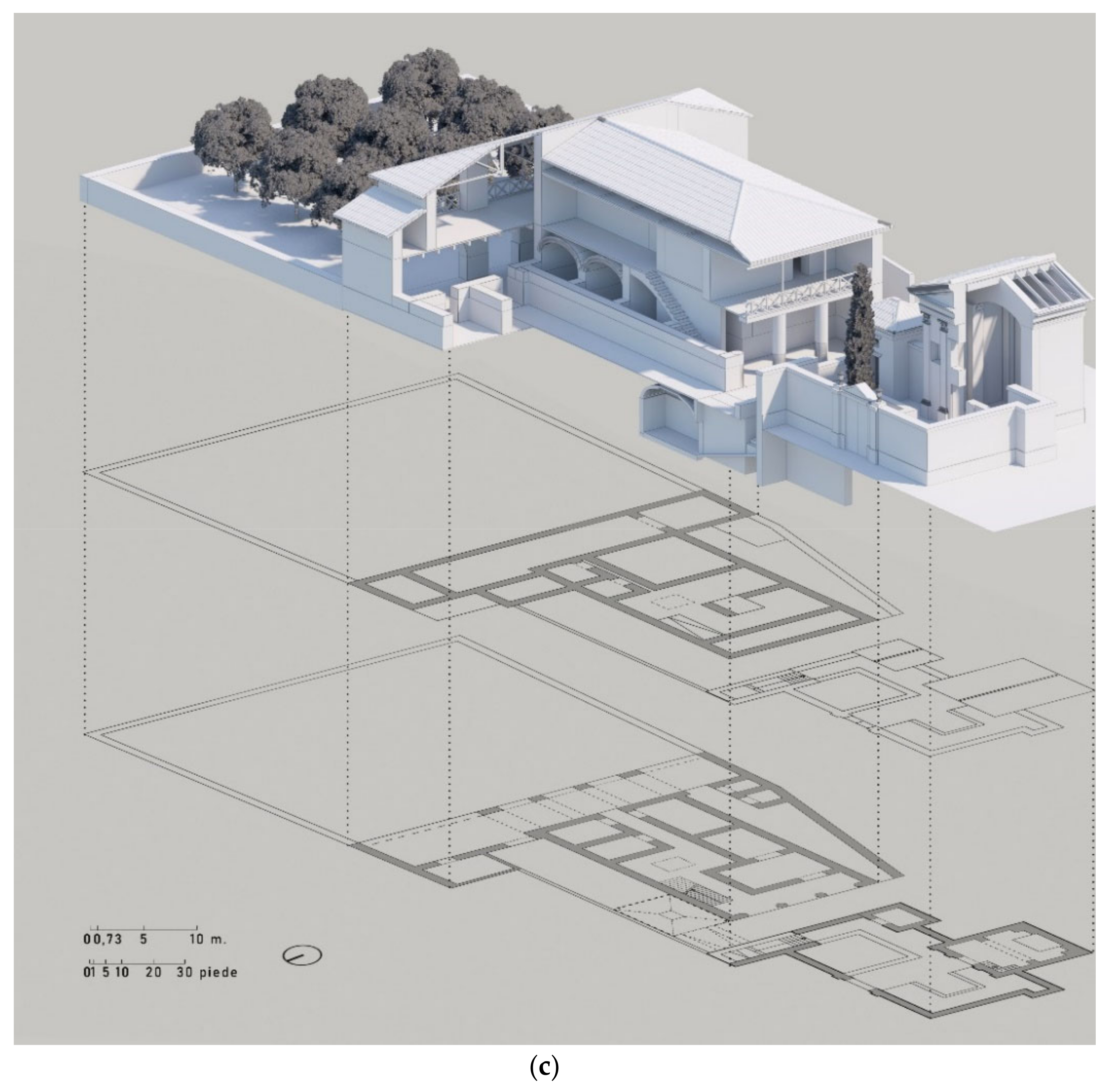
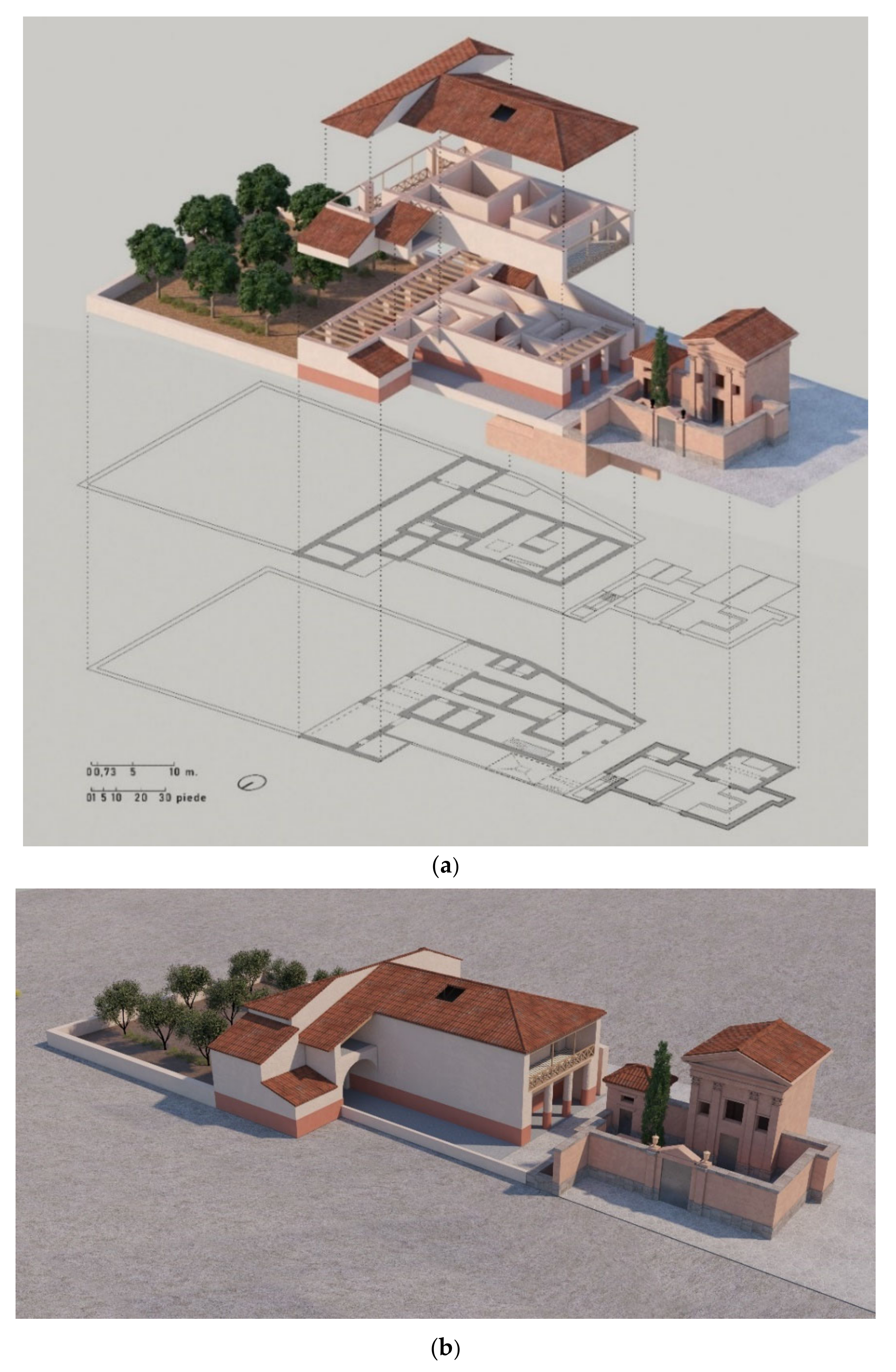
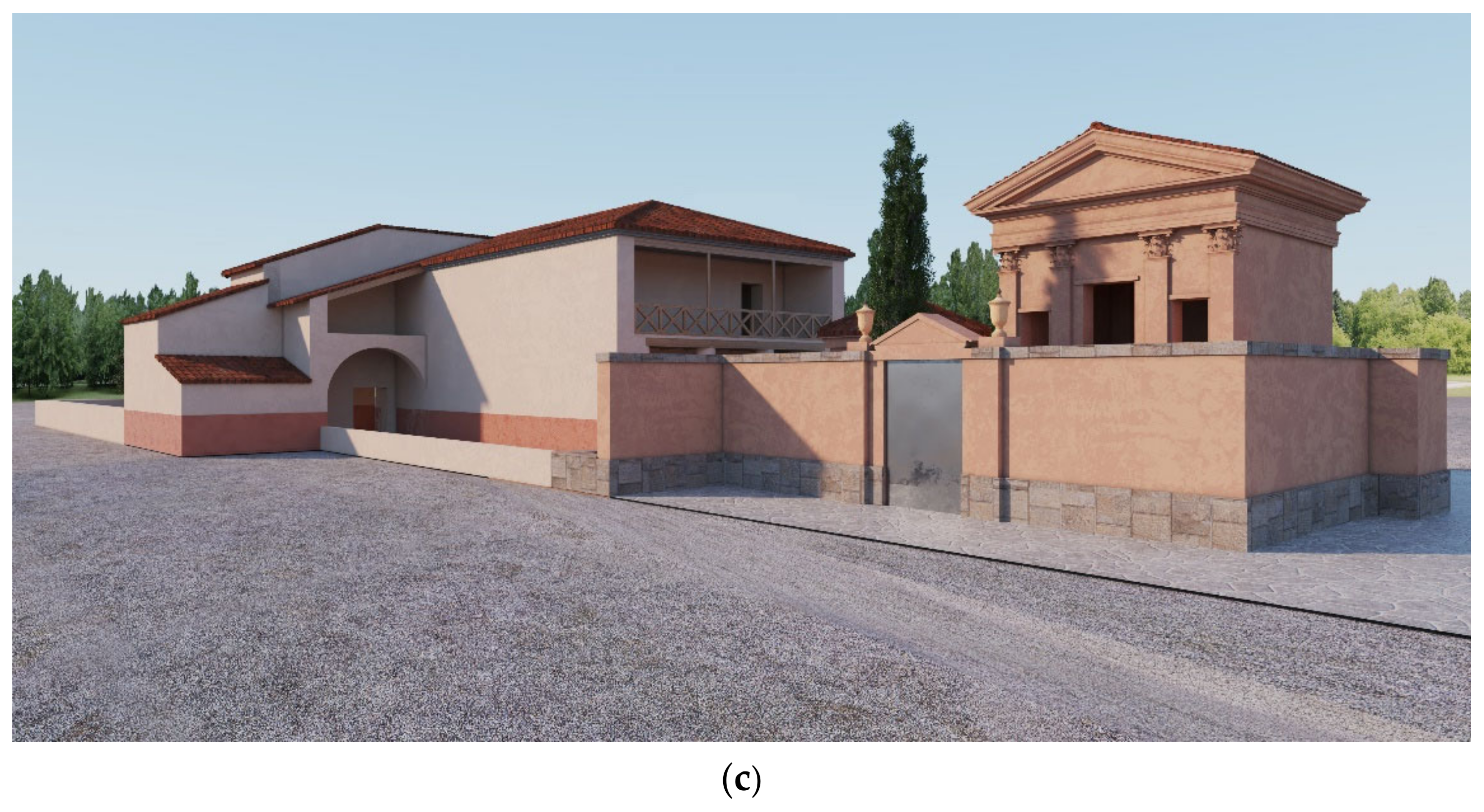
The 3D model of the villa and the temple (Figure 7 and Figure 8) was then produced inside Revit software because of the possibility of using procedural modelling. All the information gathered through the analysis of the archival and bibliographic documentation, the calculations done on the measurements, and the plans engraved on the slab permitted us to reach an accurate reconstruction of the building. As shown in the figures, the process started with the planimetric drawing of the three parts of the building complex, readjusted with the calculation of the scale reductions. Based on this information, and with the help of coeval examples still visible, the vertical structures were recreated.
4. Discussion
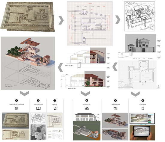
The cognitive process was therefore supported by planning digital virtualisation in the “direct” form. The procedure involved the following steps:
- -
- classification of the construction elements (semantic);
- -
- geometry extraction (segmentation);
- -
- BIM (according to the level of detail and development established); and
- -
- structuring of the taxonomic system of information and sub-models.
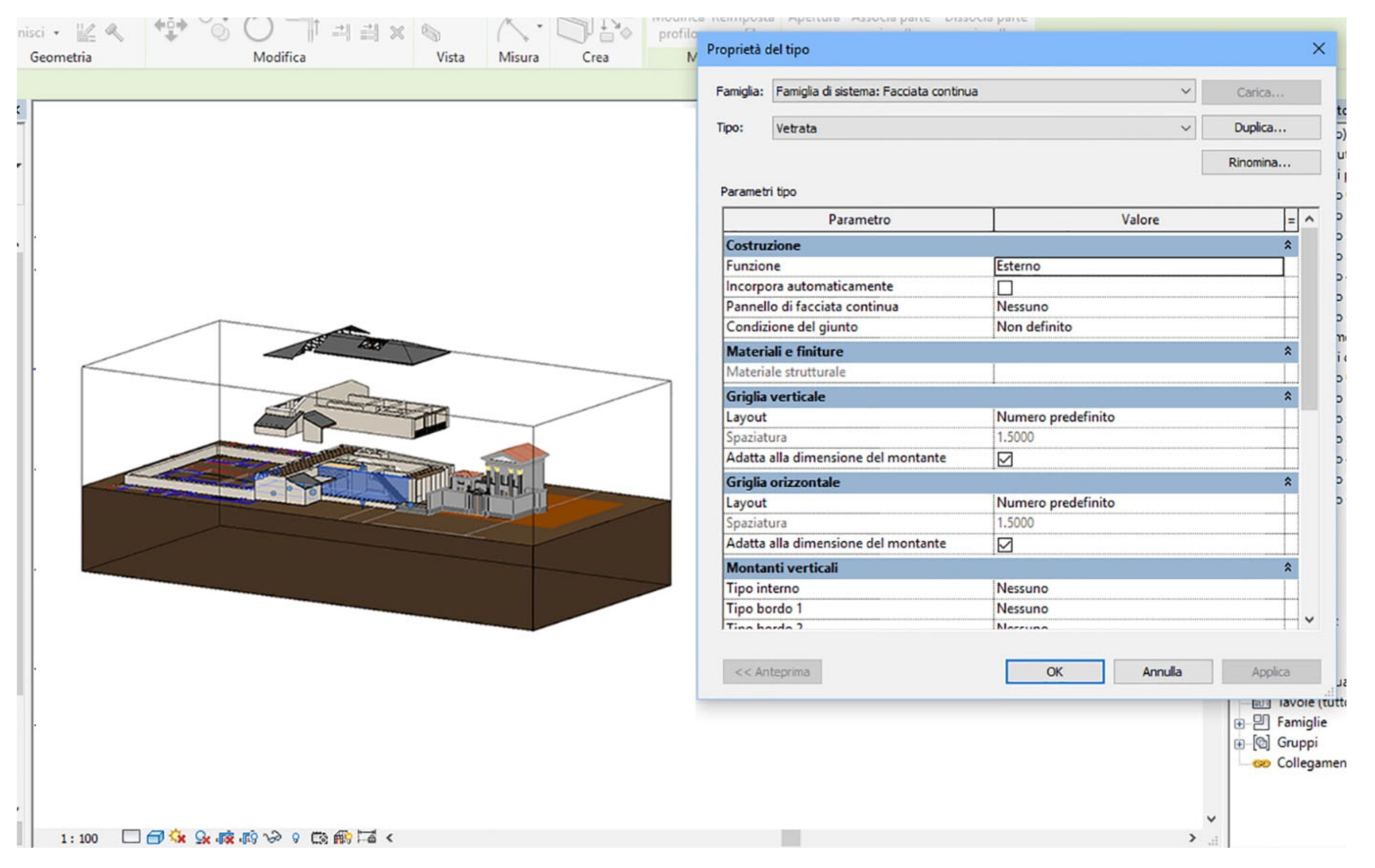
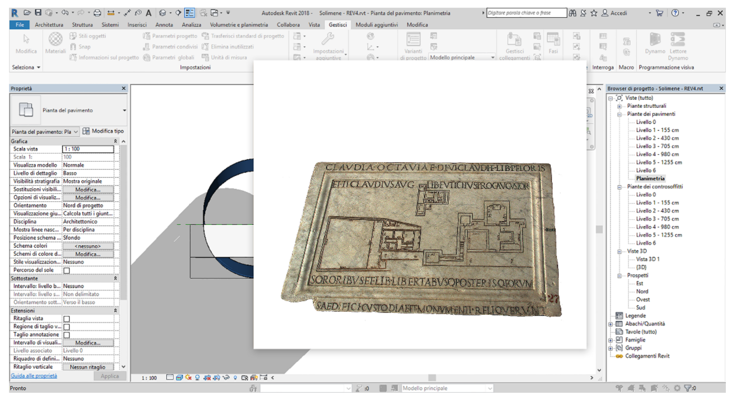
From the CAD planimetry imported into the Revit software, the geometries were connected to and associated with exclusive types technologically determined and stored in the dedicated system instructions (Figure 9). In other words, the identified surfaces were linked to contents of exclusive types (families) [32].
In the simulated space, which can also be navigated in an immersive way, the complexity of the space–time experience in the past, reserved usually for the physical use of architectures, is now recovered. Strolling in an artificial space, when it is not tautologically exhausted in an autistic virtuality, makes the experience fluid and immediate, helps one to become familiar with the problem to be analysed and solved, and guides the reconfiguration of the relationship between the observer and the object. Changing the point of view changes the mind’s eye. The more the system is adaptable to immersive navigation, the more the contents are shaped, oriented by the user’s cultural background, desires, and expectations, and recorded with extreme precision and speed with the technological systems available.
Aware of the pitfalls that interpretations run into, and at the same time persuaded by the opportunity to ‘remedy’ the critical contents in order to continue performing the work of exegesis that updates the inherited heritage [40], the authors explored the potential of the model built with Revit Autodesk software 2020 (Figure 10). This seems to guarantee an adequate level of control over the virtual space, which is suitable for:
- -
- sharing acquisitions that can be implemented and modified over time according to versatile procedures;
- -
- offering an interoperable system to compare alternative manufacturing processes; and
- -
- proposing spaces for collaboration to involve and satisfy a public that is variously erudite and qualified.
With regard to this last point, “recreating” intangible heritage is a need for those who promote the advancement of scientific research in relation to civil commitment and economic development [41]. Originally, visitors to a cultural heritage site had the training to understand the works; today, “consumers of culture” queue up patiently to perform the ritual of the “visit” such that the paradigm has passed from a single communication to an absorption of information [42] (p. 154). With the transition from analogue to digital culture, the way that cultural heritage sites are used has changed radically and with it the way of preserving, disseminating information about, and protecting them. It is necessary to take into account language as a complex system of signs used subjectively by the human mind to give meaning to what has been seen and studied. An aspect reconsidered in the contemporary panorama, not only from a philosophical point of view [43] (pp. 565–574) but also from a constructive operational point of view [41], is the means of digital communication. This type of communication is modelled starting from the characteristics and purposes identified with the old media, but rethought on the basis of innovations [44]. From this perspective, an online deposit was set up for the issues addressed using the free service made available by Sketchfab. This allows one to view the downloadable templates on any smartphone or tablet computer.
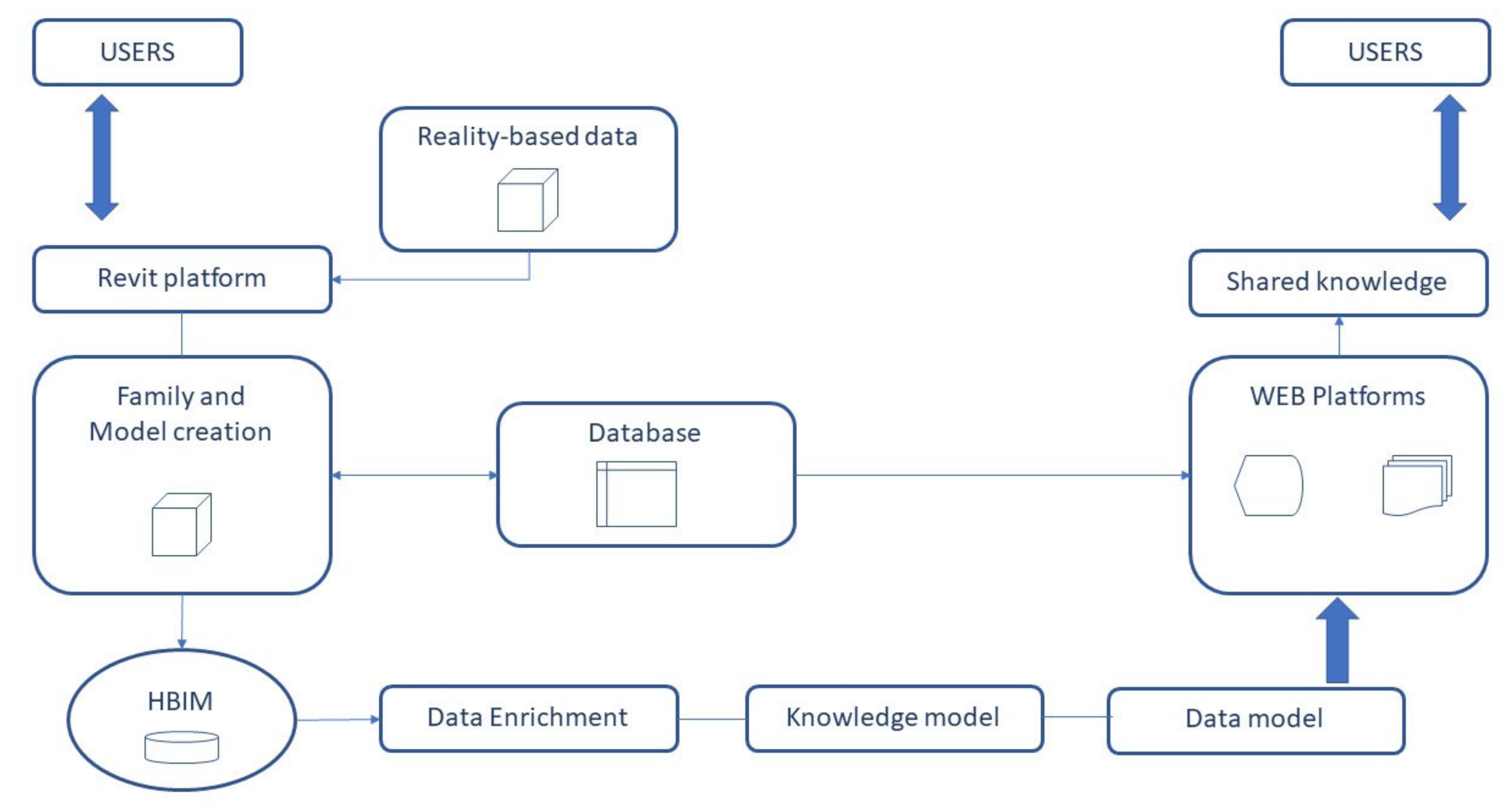
The final objective, currently in progress, is focused on the opportunity to create a system that can advance our knowledge of the documentation processes (Figure 10) of the asset in question but which at the same time discloses the themes analysed according to social and economic strategies that have repercussions for the protection and enhancement of the analysed finds [45] (pp. 13–39). Different communication and content construction strategies offer the possibility of using AR and VR, which, independently or in synergy with each other, are suitable for remedying the mathematical rationality recognised by the Perugia table in order to satisfy the identified research objectives [46], which include:
- Focusing on the reconstruction of the model and documenting the reasons;
- Comparing alternative manufacturing processes;
- Backdating some aspects of the history of the graphical representation;
- Satisfying a variously erudite and qualified public;
- Disseminating awareness and educating users;
- Encouraging policies for the protection and enhancement of digitised assets; and
- Discussing the organisational characteristics of CDE platforms.
The progress of the work will rely on the completion of the HBIM platform with all the gathered information and the completion of the VR application. The idea is to present a pipeline that can be easily adapted to similar artefacts in order to provide a robust and accurate method for the 3D reconstruction of ancient buildings.
5. Conclusions
A virtual reconstruction of a monumental complex of the imperial era is based on a scrupulous examination of it. An unprecedented dimensional analysis was validated by photogrammetric restitution of the bas-relief. A review of the process and a proportioning of the parts then guided the transposition of the quantitative data into qualitative data. In the absence of archaeological traces, the philological reconstruction used virtual modelling to mathematically control the passage from the interpretation carried out on the “iconographies” of the survey to the digital construction. This is a legitimate operation on a scientific level that is founded on the transparent collection of goals and paradigms [47] as well as on the transparency of the interpretative process of historical sources and documents on which the modelling is based.
In light of the London charter [48] for the virtual visualisation of cultural heritage (http://www.londoncharter.org (2009) (accessed on 27 November 2021) and the subsequent “Principles of Sevilla” (2012)), as well as the UNESCO recommendations [15,17] shared in international scientific contexts [49], p. 60, the results are repeatable in an application of the “falsification principle” and self-correction [16]. The virtual reconstruction was carried out in Autodesk Revit. This software allows expert users to understand the nature and purposes of the developed product, since it links the geometric detail to the materials and technologies used. The level of digital maturity of the reconstructed model is not high; according to US standards, the «normalised LOD» proposes a model with qualitative and quantitative attributes of type C (level of development of objects and geometric attributes: LOD A, symbolic object; LOD B, generic object; LOD C, defined object; LOD D, detailed subject; LOD E, specific object; LOD F, executed object; LOD G, updated object) [48]. If, on the other hand, it refers to European standards drawn from international agreements (LOI, UNI EN ISO 19650), the geometric “representations/virtualisations” use a Level of Information Need linked to technical data sheets. However, nothing prevents us from implementing or self-correcting the data in order to quickly modify the formal choices or dwell on the reconstructive path of the model to compare alternative manufacturing processes. Both aspects are useful for developing a VR/MR-based approach to:
- building spaces for collaboration, independently or in synergy with each other;
- involving, disseminating, and educating a public that is variously erudite and qualified;
- encouraging policies for the protection and enhancement of digitised assets;
- developing tools that allow for the intelligent use of processes that direct the design and collaboration of multiple users and multiple roles; and
- discussing the “intelligent” sharing of sources and analyses elaborated in diachronic projects, wisely stimulating subjective collaboration within a predetermined path.
The techniques and languages of production and the distribution of information evolve rapidly, pushing us towards a multimodal representation of information. Following the “rules of the game”, the user is in charge of archiving, sharing, and managing data in a common data environment.
CDE can include the context and explore the functionality of the interfaces that create and condition the user experience. The goal is configured as a willingness to involve forms of planning relating to the transmission and communication of existing assets to encourage multiuser functions. The aim requires the manipulation of heterogeneous materials with coherent methodologies and tools. This passes from hyper-realistic simulations representative of real data to progressively abstract ethereal transparencies to distinguish the real from the hypothetical and the material from the immaterial.
It is a question of recognising how the systematic production of structured data, starting from the studied find, proves to be decisive for the capitalisation of knowledge and for efficient decision-making processes. At the centre of the communication potential there are information technologies connected to shared network services [45]. Organised data structures are increasingly replacing massive data clouds [49].
With the help of ‘learning’ machines, the preferences of individuals are conveyed and lead to information supports. This can be reached through alternating dynamic paths that emphasise interaction and the choice of visual, auditory, and tactile interfaces. The data encourage reflection on the architectural contents of the slab in terms of civil commitment and economic development.
The ongoing objective therefore focuses on the opportunity to shift the interest in representation from the physical characteristics of the exhibit to the representation of a digital ecosystem suitable for developing a cultural vision of the aspects that bind it to the Imperial culture, which is today recognised as the origin of the European community. The modelling and digitisation process of the case study led us to distinguish multidisciplinary aspects since they refer to the characteristics that express the complexity of matter, form, spaces, behaviours, and transformations. The analysis of these data highlights the specific production mechanisms that contribute to building the technical–cultural knowledge on which to develop social and economic interests. What follows is the opportunity to create a system that, managed by a dedicated platform, app, and open-source software, attracts different users towards a single source of information content capable of “remedying” the inherited heritage to promote the advancement of scientific research in relation to social and economic development.
Seen through the lens of current events, the analysis of the data acquired and processed highlights the specific production mechanisms of each discipline. It also sets in motion actions progressively directed towards the idea of scientific knowledge articulated around the interdependence of space–time forms, the configuration of objects, and models. This contributes to building collective knowledge systems.
Between premises and purposes, how is possible to direct the design and collaboration of multiple users and multiple roles? In addition, in a specific case, who has to do what? How long will it take? How is it to be done?
The image shown in Figure 9 sketches an initial attempt to provide a project breakdown structure (PBS). From this structured organisation derives the stages of a path that arranges the elements along a timeline of actions. We aim to try to use an emblematic way of acting to think about the information space.
These reconstructive hypotheses should accompany the shift from the representation of physical characteristics to the representation of an adaptable digital ecosystem around semantic needs. This is no longer or not just only a cloud formed from the accumulation of a massive amount of data but on the contrary a multi-dimensional data production and storage system. This process is suitable for developing a shared cultural vision that is intelligible not only for cultural but also for socio-economic purposes.
Author Contributions
Conceptualisation, A.R.; methodology, A.R. and S.G.B.; validation, A.R., S.G.B. and S.L.G.; writing—original draft preparation, S.G.B.; writing—S.G.B. and A.R.; supervision A.R.; photogrammetry S.G.B.; 3D modelling, S.L.G.; HBIM setup, S.L.G., S.G.B. and A.R. All authors have read and agreed to the published version of the manuscript.
Funding
This research received no external funding.
Data Availability Statement
The model can be found on Sketchfab: https://sketchfab.com/3d-models/tavola-perugia-3-d4bb0e6229514c1884b56476e14a1179 (accessed on 26 November 2021).
Conflicts of Interest
The authors declare no conflict of interest.
References
- Pietroni, E.; Ferdani, D. Virtual Restoration and Virtual Reconstruction in Cultural Heritage: Terminology, Methodologies, Visual Representation Techniques and Cognitive Models. Information 2021, 12, 167. [Google Scholar] [CrossRef]
- Clark, J.T. The Fallacy of Reconstruction. In Cyber-Archaeology; Forte, M., Ed.; Archeopress: Oxford, UK, 2010; pp. 63–73. [Google Scholar]
- Baker, D. Defining Paradata in Heritage Visualization. In Paradata and Transparency in Virtual Heritage; Bentkowska-Kafel, A., Denard, H., Baker, D., Eds.; Routledge: London, UK, 2012; pp. 238–251. [Google Scholar]
- Barratt, R.P. Defining a Methodology for 3D Approximations in Archaeology: The Issue with Alternative Models. In Proceedings of the 23rd International Conference on Cultural Heritage and New Technologies, Vienna, Austria, 12–15 November 2018; p. 12. [Google Scholar]
- Daniotti, B.; Pavan, A.; Lupica Spagnolo, S.; Caffi, V.; Pasini, D.; Mirarchi, C. Collaborative Working in a BIM Environment (BIM Platform). In BIM-Based Collaborative Building Process Management; Springer Tracts in Civil Engineering; Springer: Cham, Switzerland, 2020. [Google Scholar] [CrossRef]
- Nieto-Julián, J.E.; Lara, L.; Moyano, J. Implementation of a TeamWork-HBIM for the Management and Sustainability of Architectural Heritage. Sustainability 2021, 13, 2161. [Google Scholar] [CrossRef]
- Banfi, F.; Brumana, R.; Stanga, C. Extended Reality and Informative Models for the Architectural Heritage: From Scan-to-BIM Process to Virtual and Augmented Reality. Virtual Archaeol. Rev. 2019, 10, 14–30. [Google Scholar] [CrossRef]
- Jordán Palomar, I.; García Valldecabres, J.L.; Tzortzopoulos, P.; Pellicer, E. An online platform to unify and synchronise heritage architecture information. Autom. Constr. 2020, 110, 103008. [Google Scholar] [CrossRef]
- Woodward, A.; Heesom, D. Implementing HBIM on conservation heritage projects: Lessons from renovation case studies. Int. J. Build. Pathol. Adapt. 2021, 39, 96–114. [Google Scholar] [CrossRef]
- Cante, M.; Manconi, D.; Cipollone, M. (Eds.) Perugia: Museo Archeologico Nazionale dell’Umbria: Chiostro Maggiore e Lapidario; Volumnia Editrice, Soprintendenza per i Beni Archeologici dell’Umbria: Perugia, Italy, 2004. [Google Scholar]
- Jallow, H.; Renukappa, S.; Suresh, S.; Alneyadi, A. Implementing a BIM Collaborative Workflow in The UK Infrastructure Sector. In Proceedings of the 2019 3rd International Conference on Information System and Data Mining—ICISDM 2019, Houston, TX, USA, 6–8 April 2019; pp. 103–108. [Google Scholar]
- UNESCO. World Heritage Cultural Landscape. 2009. Available online: https://unesdoc.unesco.org/ark:/48223/pf0000187044 (accessed on 27 November 2021).
- UNESCO. Nara Document on Authenticity; Retrieved on November (1994). 2016. Available online: https://www.icomos.org/charters/nara-e.pdf (accessed on 27 November 2021).
- UNESCO. Convention for the Safeguarding of Intangible Cultural Heritage. 2003. Available online: https://ich.unesco.org/en/convention (accessed on 27 November 2021).
- Tacitus, P.G.C. Libri Qui Supersunt, Tom. I: Ab Excessu Divi Augusti (Annales) (Bibliotheca Scriptorum Graecorum et Romanorum Teubneriana); (114–120 d.C. c.a); K.G. Saur Verlag: Munich, Germany, 2008; Volumes 60–64, pp. 154–196. ISBN1 3598718349. ISBN2 9783598718342. [Google Scholar]
- Madeo, L. Ottavia: La Prima Moglie di Nerone; Mondadori: Milano, Italy, 2006. [Google Scholar]
- Rodríguez Almeida, E. Forma Urbis Antiquae. Le Mappe Marmoree di Roma tra la Repubblica e Settimio Severo. In École Fra-nçaise de Rome: Le Forme Marmoree di Roma di Tradizione Augustea; Publications de l’École française de Rome: Rome, Italy, 2002; Volume 79, p. 2013. Available online: https://books.openedition.org/efr/1886?lang=en (accessed on 27 November 2021).
- Meneghini, R. Pianta di Perugia. In Formae Urbis Romae: Nuovi Frammenti di Piante Marmoree Dallo Scavo dei Fori Imperiali; Meneghini, R., Santangeli, V.R., Valenzani, R.S., Eds.; L’Erma di Bretschneider: Roma, Italy, 2006; pp. 31–34. [Google Scholar]
- Heinrich, J.; Hülsen, C. Topographie der Stadt Rom im Alterthum; Weidmannsche Buchhandlung: Berlin, German, 1878. [Google Scholar]
- De Baillou, G. Memoria intorno al sistema metrico agrario degli antichi Romani del cavalier Giovanni De Baillou letta all’adunanza dei Gergofili del dì 27 febbrajo 1818. In I Georgofili; Tomo I, Trim. I; Atti della Accademia dei Georgofili: Firenze, Italy, 1818; pp. 207–233. [Google Scholar]
- Mazzi, A. Nota metrologica. In Archivio Storico Lombardo; Lombard Historical Society: Milan, Italy, 2002; pp. 1000–1002. Available online: https://www.lombardiabeniculturali.it/archivi/unita/MIUD0AA590/ (accessed on 27 November 2021).
- Gatti, G. La Pianta Marmorea Severiana in Topografia ed Edilizia di Roma Antica; Ris. An. Articoli di Guglielmo Gatti Pubblicati dal 1934 al 1979; “L’Erma” di Bretschneider: Roma, Italy, 1989; p. 1874. [Google Scholar]
- Vitruvio, P.M. I Dieci Libri dell’Architettura di M. Vitruuio. Tradotti & Commentati da Monsignor Barbaro Eletto Patriarca d’Aquileggia. Venezia, Francesco Marcolini, 1556. Available online: https://www.palladiomuseum.org/library/libroantico/71?lang=en (accessed on 27 November 2021).
- Bodel, J. Roman Tomb Gardens. In Gardens of the Roman Empire; Jashemski, W.F., Gleason, K.L., Hartswick, K.J., Malek, A.A., Eds.; Cambridge University Press: Cambridge, UK, 2017; pp. 199–242. [Google Scholar]
- Russo, F. Il Controllo del Territorio, da Federico II di Svevia All’arma dei Carabinieri; Ministero della Difesa: Roma, Italy, 2019.
- Heidegger, M. Sein und Zeit; Max Niemeyer Verlag: Tübingen, Germany, 1967; Available online: https://taradajko.org/get/books/sein_und_zeit.pdf (accessed on 27 November 2021).
- Argan, G.C. Modulo-misura e modulo-oggetto. In Progetto e Destino; Casa editrice il Saggiatore: Milano, Italy, 2021; pp. 104–115. [Google Scholar]
- De Fusco, R. Il Codice dell’Architettura Antologia di Trattatisti; Edizioni Scientifiche Italiane: Napoli, Italy, 1968. [Google Scholar]
- Hülsen, C.C.F. Piante Icnografiche Incise in Marmo. Mittheilungen des Kaiserlich Deutschen Archäeologischen Instituts Roemische Abteilung 1890, 5, 208–210. Available online: https://www.worldcat.org/title/mitteilungen-des-deutschen-archaeologischen-instituts-roemische-abteilung/oclc/8799287#relatedsubjects (accessed on 27 November 2021).
- Fontana, V.; Morachiello, P. l’Arco Trionfale e Onorario Romano. Available online: http://www.engramma.it/eOS/index.php?id_articolo=1703 (accessed on 27 November 2021).
- Brusaporci, S.; Maiezza, P.; Tata, A. Framework for architectural heritage HBIM semantization and development. Int. Arch. Photogramm. Remote Sens. Spat. Inf. Sci. 2018, XLII-2, 179–184. [Google Scholar] [CrossRef] [Green Version]
- Fai, S.; Graham, K.; Duckworth, T.; Wood, N.; Attar, R. Building information modelling and heritage documentation. In Proceedings of the 18th International Conference on Virtual Systems and Multimedia, Milan, Italy, 2–5 September 2012. [Google Scholar]
- Adam, J.P. L’Arte di Costruire Presso i Romani: Materiali e Tecniche; Longanesi: Milan, Italy, 2017. [Google Scholar]
- Choisy, A. L’Art de Bâtir Chez les Romains; Paris Rist. Anast.; Armando Forni Editore: Bologna, Italy, 1873. [Google Scholar]
- Choisy, A. L’Art de Bâtir Chez les Égyptiens; E. Rouveyre: Paris, France, 1904. [Google Scholar]
- Cejka, J. Tonnengewölbe und Bogen islamischer Architektur: Wölbungstechnik und Form. Ph.D. Dissertation, Technology University Fachbereich Architektur, München, Germany, 1978. [Google Scholar]
- El-Naggar, S. Les Voûtes Dans l’Architecture de l’Égypte Ancienne; Institut Français d’Archéologie Orientale: Le Caire, Egypt, 1999. [Google Scholar]
- Cipriani, L.; Fantini, F.; Bertacchi, S. Survey and representation of vaults and cupolas: An overview on some relevant Italian UNESCO sites. In Proceedings of the International Conference on Virtual Systems & Multimedia (VSMM), Hong Kong, China, 9–12 December 2014; pp. 50–57. [Google Scholar] [CrossRef]
- Heisel, J.P. Antike Bauzeichnungen; Wissenschaftliche Buchgesellschaft: Darmstadt, Germany, 1993. [Google Scholar]
- Bolter, J.D.; Grusin, R. Remediation—Understanding New Media; MIT Press: Cambridge, UK, 1999. [Google Scholar]
- UNESCO. Managing Cultural World Heritage; UNESCO World Heritage Centre: Paris, France, 2013; Available online: https://whc.unesco.org/en/managing-cultural-world-heritage/ (accessed on 27 November 2021).
- Irace, F. (Ed.) Design & Cultural Heritage: Immateriale Virtuale Interattivo; Electa: Milano, Italy, 2013; Volume 1. [Google Scholar]
- Landi, L. Cassirer, Husserl e l’ermeneutica. Rivista di Storia della Filosofia 1984, 1991, 565–574. [Google Scholar]
- McLuhan, M. Understanding Media: The Extension of Man; MITT Press: Cambridge, MA, USA, 1967. [Google Scholar]
- Bortolotti, A.; Calidoni, M.; Mascheroni, S.; Mattozzi, I. Per l’Educazione al Patrimonio Culturale: 22 Tesi; Franco Angeli: Milano, Italy, 2008. [Google Scholar]
- Silberman, N.; Purser, M. Collective memory as affirmation: People-centred cultural heritage in a digital age. In Heritage and Social Media: Understanding Heritage in a Participatory Culture; Giaccardi, E., Ed.; Routledge: Abingdon, UK, 2012; pp. 13–39. [Google Scholar]
- Bentkowska-kaFel, A.; Denard, H. Paradata and Transparency in Virtual Heritage; Routledge: Abingdon, UK, 2012. [Google Scholar]
- Hugh, D. A new introduction to The London Charter. In Paradata and Transparency in Virtual Heritage; Routledge: Abingdon, UK, 2012; pp. 57–71. [Google Scholar]
- Fleishner, E. “Che cos’è Oggi la Crossmedialità?”, Treccani.it WebTV. Available online: http://www.treccani.it/webtv/videos/Int_Edoardo_Fleischner_crossmedialita.html (accessed on 24 November 2021).
Figure 1.
National Archaeological Museum of Perugia, “Marble plan with funerary inscription of a freedwoman and a freedman of Octavia and Nero” Marble 54–68 AC Coll. Gaddi Coll. Oddi, Inv. Com. 486. Rep. n. 45 (CIL VI, 2, 9015).
Figure 1.
National Archaeological Museum of Perugia, “Marble plan with funerary inscription of a freedwoman and a freedman of Octavia and Nero” Marble 54–68 AC Coll. Gaddi Coll. Oddi, Inv. Com. 486. Rep. n. 45 (CIL VI, 2, 9015).

Figure 2.
Vectorisation of the unified iconographies in the reduction scale. Comparison of the data obtained from the no-contact survey, from the analyses available in the literature, and from the calculation of the annotated measurements in Roman figures. Hypothesis of the derived commensuration grids for the ground and the upper floor: (a) drawing and measurements of the lower floor; (b) drawing and measurements of the upper floor; and (c) comparison between the vectorisation done on the orthophoto and the reconstructed 3D model based on recalculated measurements.


Figure 3.
Aedificium custodiae. Distribution of the rooms from [12] (Figure 13, Chapter IV). The figure compares the ground floor and the mezzanine floor of the aedificium custodiae.
Figure 3.
Aedificium custodiae. Distribution of the rooms from [12] (Figure 13, Chapter IV). The figure compares the ground floor and the mezzanine floor of the aedificium custodiae.

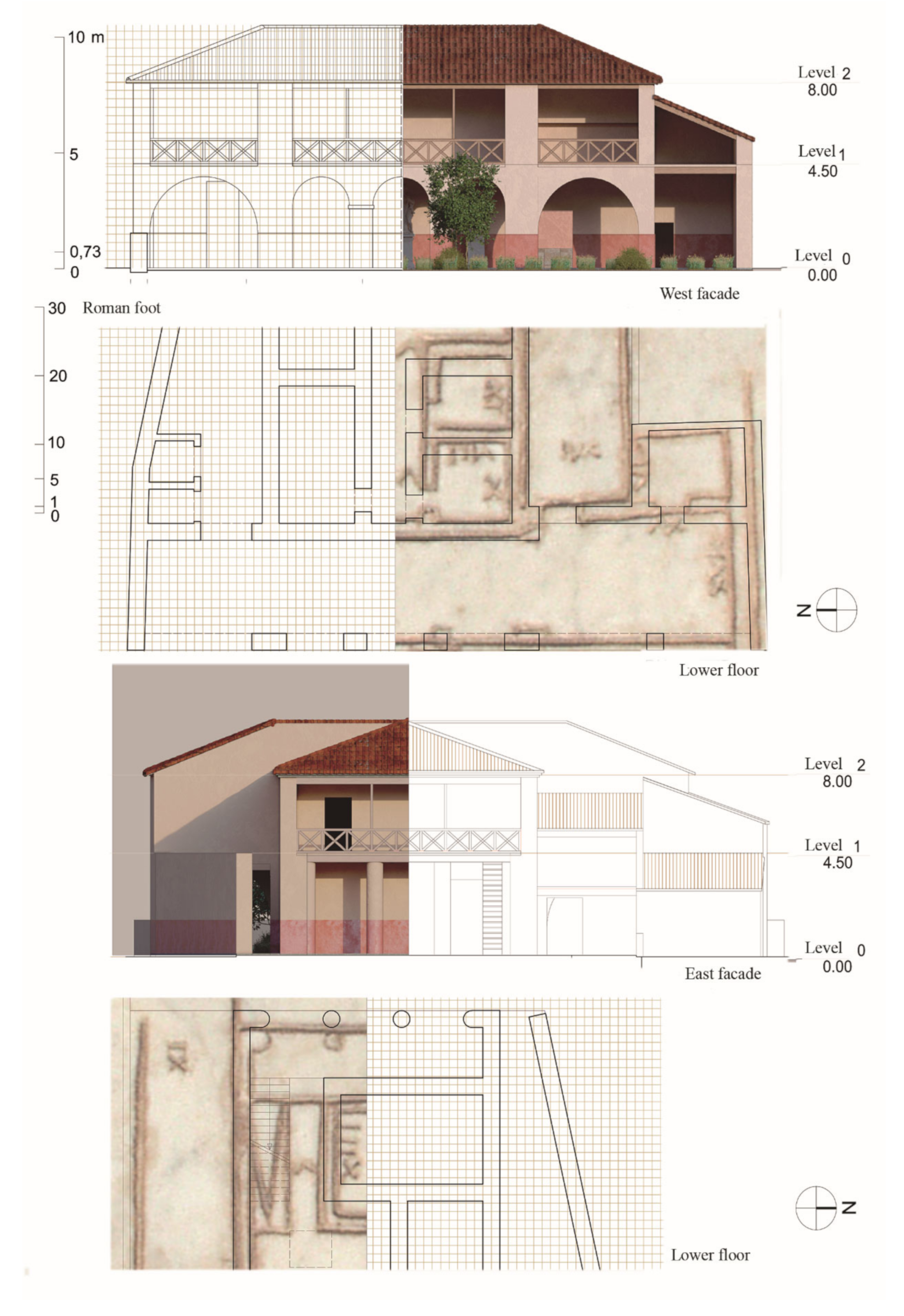
Figure 4.
Reconstructive hypothesis of the Aedificium custodiae’s East and West façades referred to the related plan.
Figure 4.
Reconstructive hypothesis of the Aedificium custodiae’s East and West façades referred to the related plan.

Figure 5.
Reconstruction of the Aedificium Monumentalis: (a) axonometric sketch by Christian Carl Friedrich Hülsen [29]; (b) the Arch of Susa at the foot of Mont Cenis, dedicated to Augustus; (c) the Arco dei Gavi, which was built along the Via Postumia in Veronanella; and (d) reconstruction of the Domus Romana, today the archaeological museum of the island of Malta.

Figure 6.
References in Revit software of the information on and characteristics of the walls.

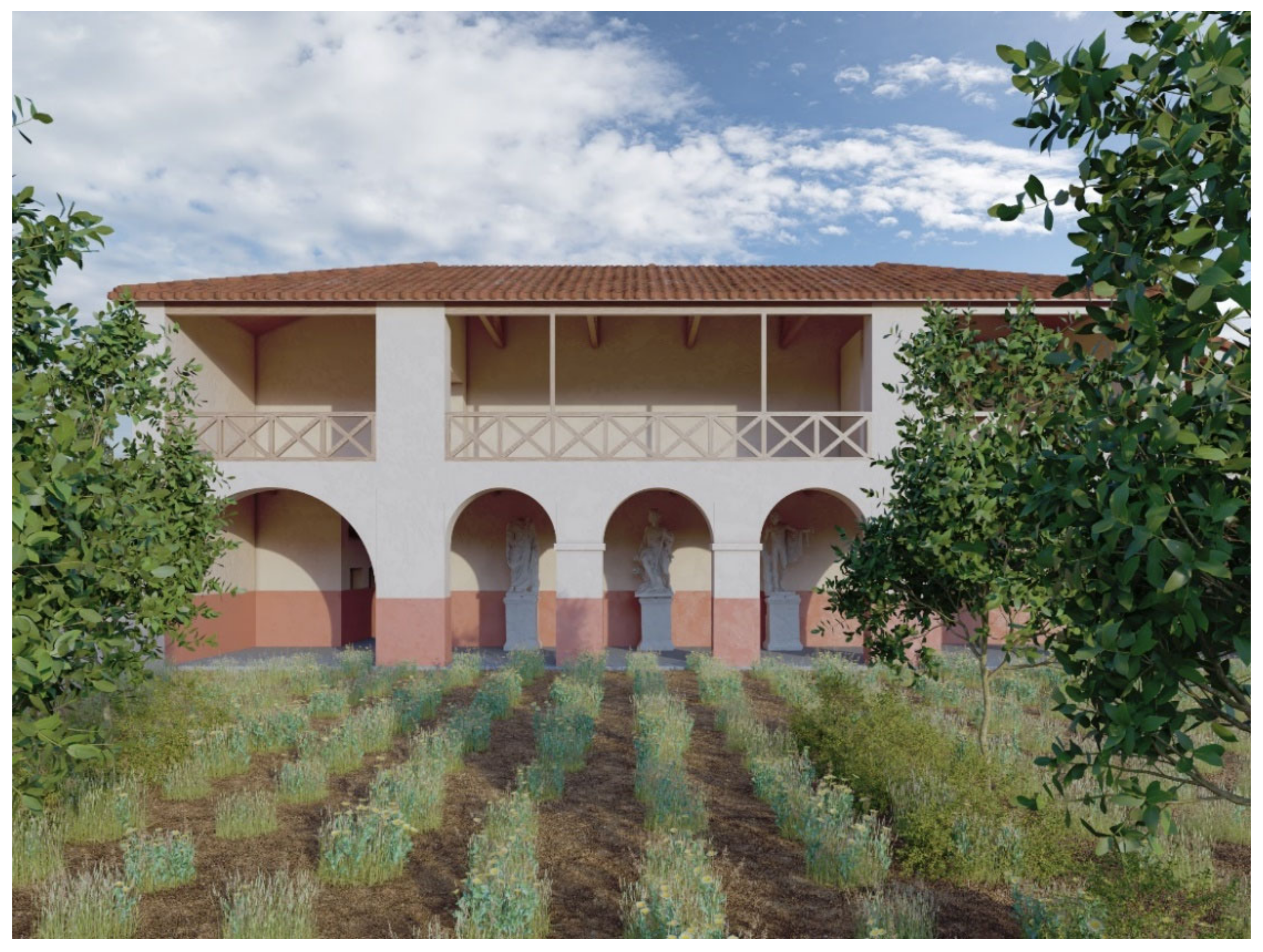
Figure 7.
Reconstructive hypothesis of the monumental complex. Rendering of the porch.

Figure 8.
Reconstructive hypothesis of the monumental complex: (a) isometric exploded view of the rendered model; (b,c) different views of the rendered model.
Figure 8.
Reconstructive hypothesis of the monumental complex: (a) isometric exploded view of the rendered model; (b,c) different views of the rendered model.


Figure 9.
The association of the information with the 3D model.

Figure 10.
Schema of the process.


Table 1.
The analysis of the dimensions engraved on the slab and the calculation of the correct ones considering mathematical proportions.
Table 1.
The analysis of the dimensions engraved on the slab and the calculation of the correct ones considering mathematical proportions.
| N. | LOWER FLOOR | Dimensions in Roman Feet. Width–Length | Measurements in cm. Width–Length | Measurements Taken from Geometry |
| Hypothetic Function | ||||
| 1. | Anterior porch | XVI–LXX | 474–2075 | 474–2419 |
| 2. | Room n 2 | V–VIS | 148–193 | 148–193 |
| 3. | Room n 3 | VI–(-) | 178–(-) | 178–181 |
| 4. | Room n 4 | XX–XI | 593–326 | 593–326 |
| 5. | Room n 5 | XII–XI | 356–326 | 356–326 |
| 6. | Room n 6 | XIII–VIIS | 385–222 | 385–466 |
| 7. | Corridor | (-)–V | (-)–148 | 782–148 |
| 8. | Room n 8 | X–VIII | 296–237 | 296–237 |
| 9. | Room n 9 | IX–VIII | 267–237 | 267–237 |
| 10. | Atrium | (-) | (-) | 313–458 |
| 11. | Staircase | (-) | (-) | 531–170 |
| 12. | Corridor | (-)–V | (-)–148 | 531–148 |
| 13. | Posterior porch | (-) | (-) | 296–857 |
| 14. | Stable | VI–(-) | 178–(-) | 178–281 |
| 15. | Garden | LXV–LXX | 1926–2075 | 2390–2419 |
| 16. | Access road | (-)–XXS | (-)–607 | 1890–445 |
| N. | UPPER FLOOR | Dimensions in Roman Feet. Width–Length | Measurements in cm. Width–Length | Measurements Taken from Geometry |
| Hypothetical Function | ||||
| 1. | Anterior porch | XS–(-) | 311–(-) | 401–495 |
| 2. | Room n 2 | (-)–XX | 474–563 | 636–593 |
| 3. | Room n 3 | XI–VII | 326–207 | 296–207 |
| 4. | Room n 4 | IX–VII | 267–207 | 267–207 |
| 5. | Atriu | XXX–(-) | 889– | 889–1005 |
| 6. | Posterior porch | (-) | (-) | 291–1005 |
Publisher’s Note: MDPI stays neutral with regard to jurisdictional claims in published maps and institutional affiliations. |
© 2022 by the authors. Licensee MDPI, Basel, Switzerland. This article is an open access article distributed under the terms and conditions of the Creative Commons Attribution (CC BY) license (https://creativecommons.org/licenses/by/4.0/).
Share and Cite
MDPI and ACS Style
Gonizzi Barsanti, S.; Giner, S.L.; Rossi, A. Towards a Multimodal Representation: Claudia Octavia’s Bequeathal. Remote Sens. 2022, 14, 429. https://0-doi-org.brum.beds.ac.uk/10.3390/rs14020429
AMA Style
Gonizzi Barsanti S, Giner SL, Rossi A. Towards a Multimodal Representation: Claudia Octavia’s Bequeathal. Remote Sensing. 2022; 14(2):429. https://0-doi-org.brum.beds.ac.uk/10.3390/rs14020429
Chicago/Turabian StyleGonizzi Barsanti, Sara, Santiago Lillo Giner, and Adriana Rossi. 2022. "Towards a Multimodal Representation: Claudia Octavia’s Bequeathal" Remote Sensing 14, no. 2: 429. https://0-doi-org.brum.beds.ac.uk/10.3390/rs14020429
Note that from the first issue of 2016, this journal uses article numbers instead of page numbers. See further details here.