
Close Observation of the Evolution Process during Initial Stage of Triggered Lightning Based on Continuous Interferometer

 , and
, and 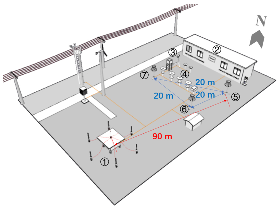
Abstract
:1. Introduction
2. Experiment and Data
3. CINTF Error Calibration for the Initial Stage of the UPL
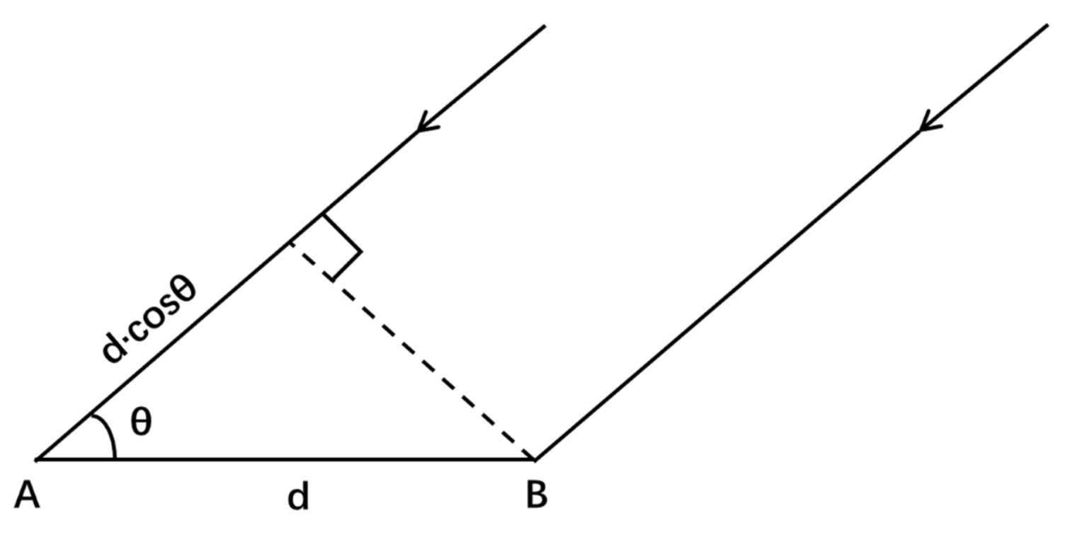
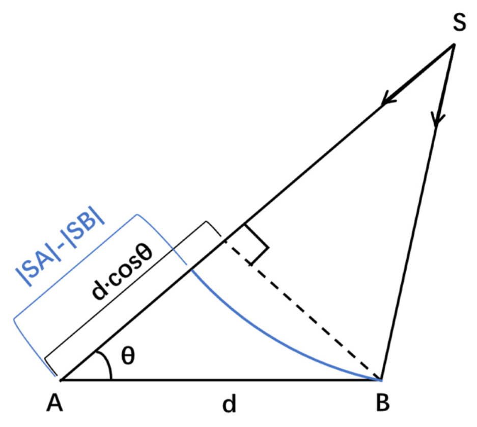
3.1. Basic Principle of CINTF Positioning
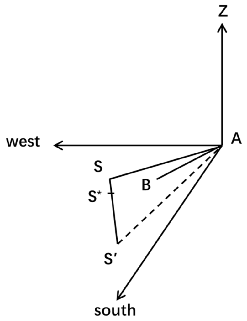
3.2. CINTF Error Calibration Method for the Initial Stage of the UPL
3.3. Analysis of CINTF Positioning Error in Initial Stage of UPL
4. Evolution Characteristics during Initial Stage of UPL: Results and Discussion
4.1. The Single Initial Process Form
4.2. The Multiple Initial Process Form
5. Conclusions
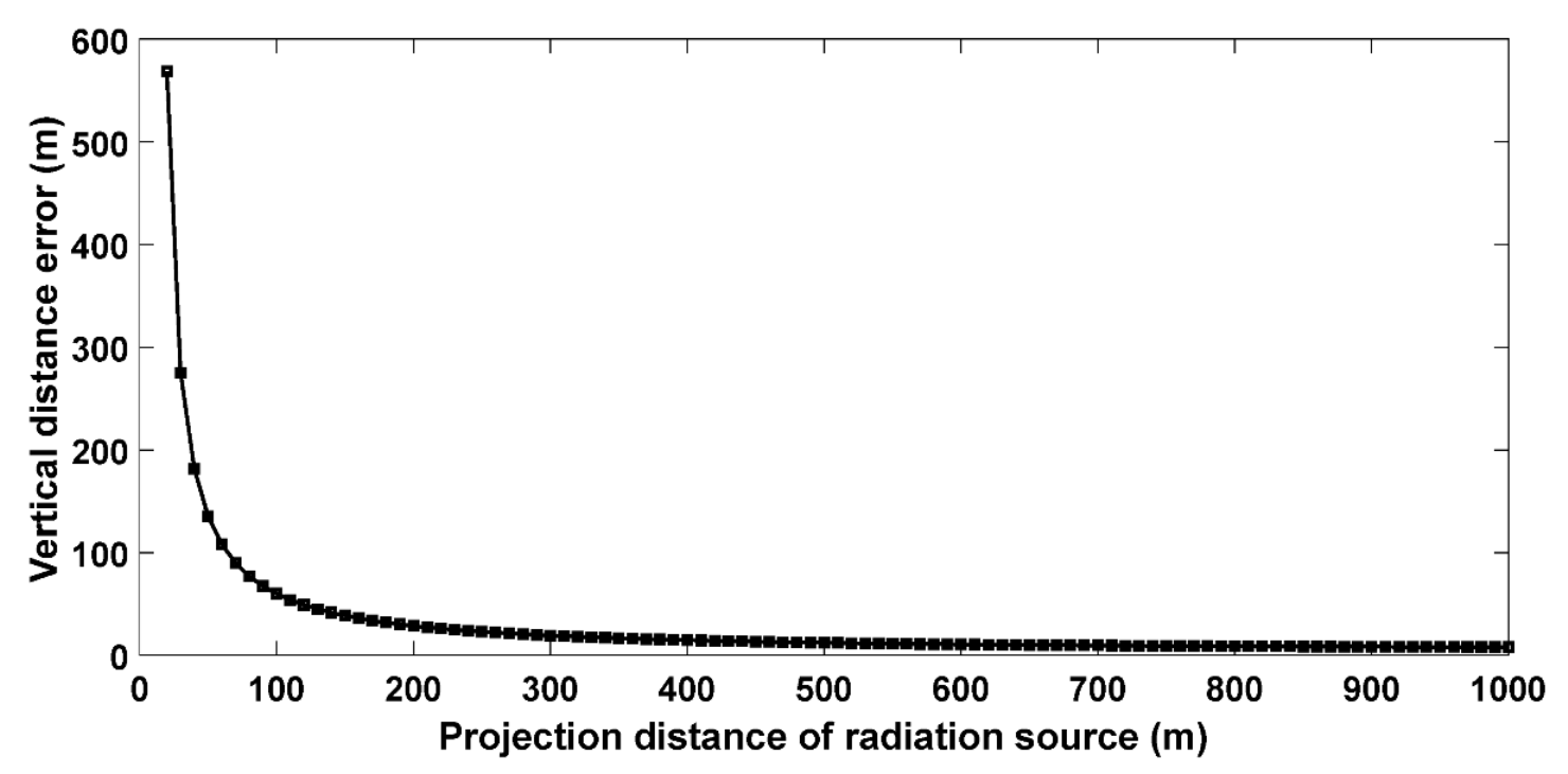
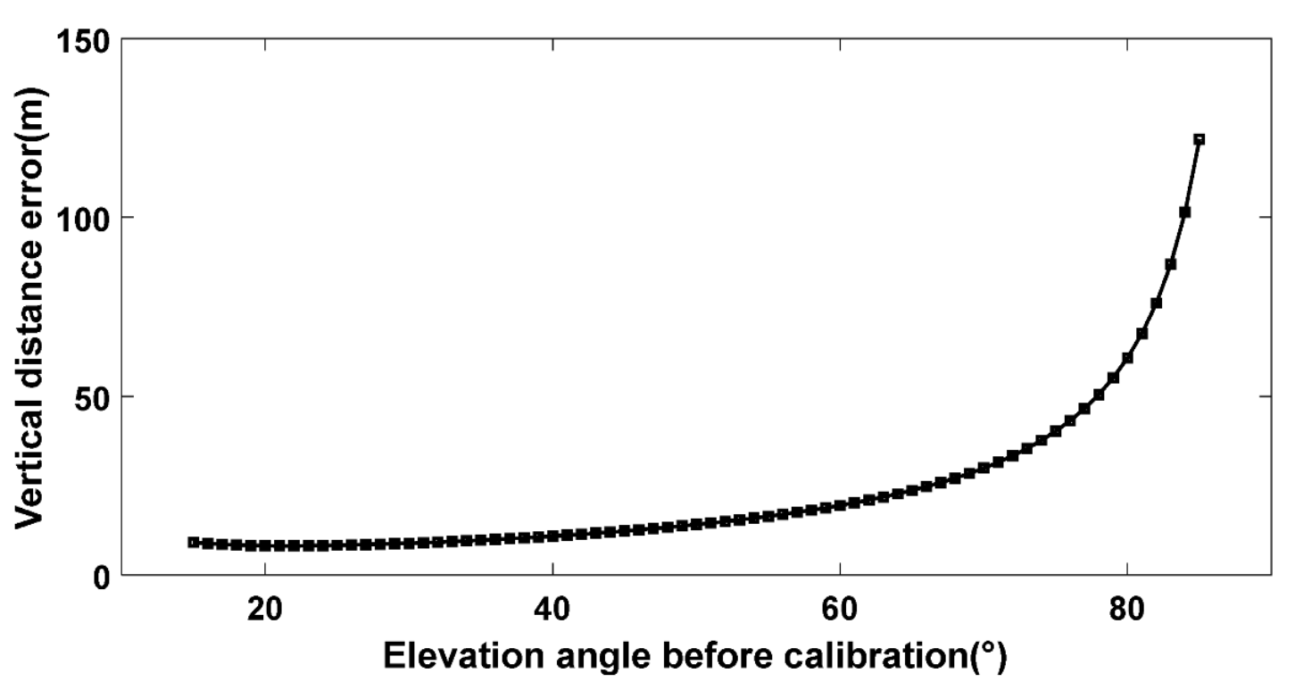
- The calibration method of a CINTF for positioning a specific short-range radiation source was proposed, and the calibration of the CINTF positioning results for the initial stage of the UPL was realized. The positioning error of the short-range radiation source caused by the basic principle of CINTF positioning was analyzed. When the azimuth angle and projection distance of the radiation source were constant, the vertical distance error of CINTF obviously increased with the increase in the elevation angle (height) of the radiation source. When the azimuth and height of the radiation source were constant, the vertical distance error of CINTF decreased obviously with the increase in the projection distance of the radiation source. For long-distance radiation sources, the vertical error of CINTF positioning was within 10 m, which shows the reliability of the conventional results of CINTF positioning. For a short-distance radiation source, the calibration method proposed in this paper improved the observation accuracy. When the elevation angles of the initial stage of the UPL were 40°, 50°, and 60°, the calibrated positioning error in altitude could be reduced by about 11 m, 14 m, and 20 m, respectively.
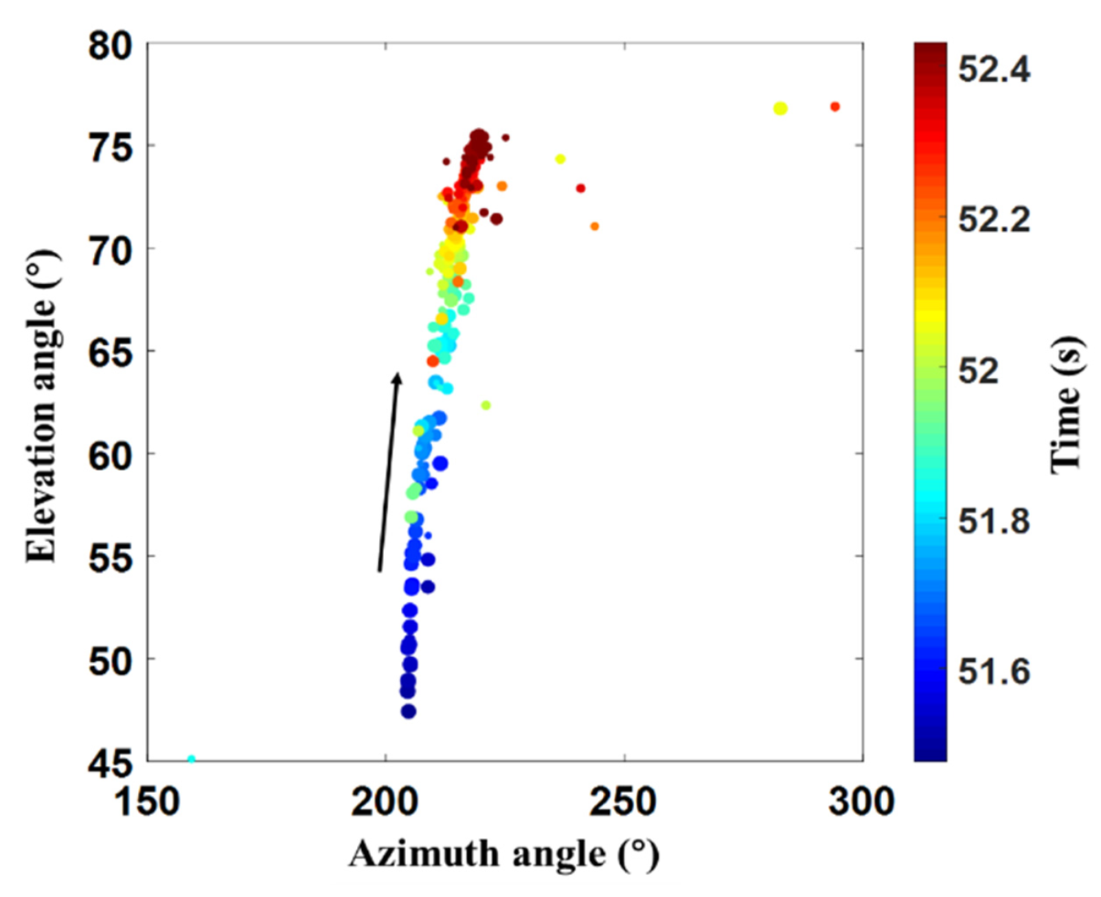
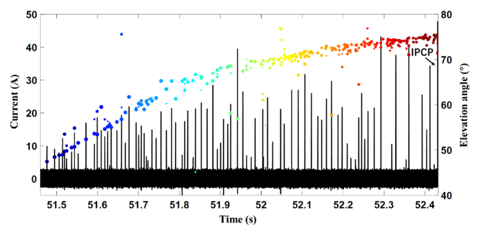
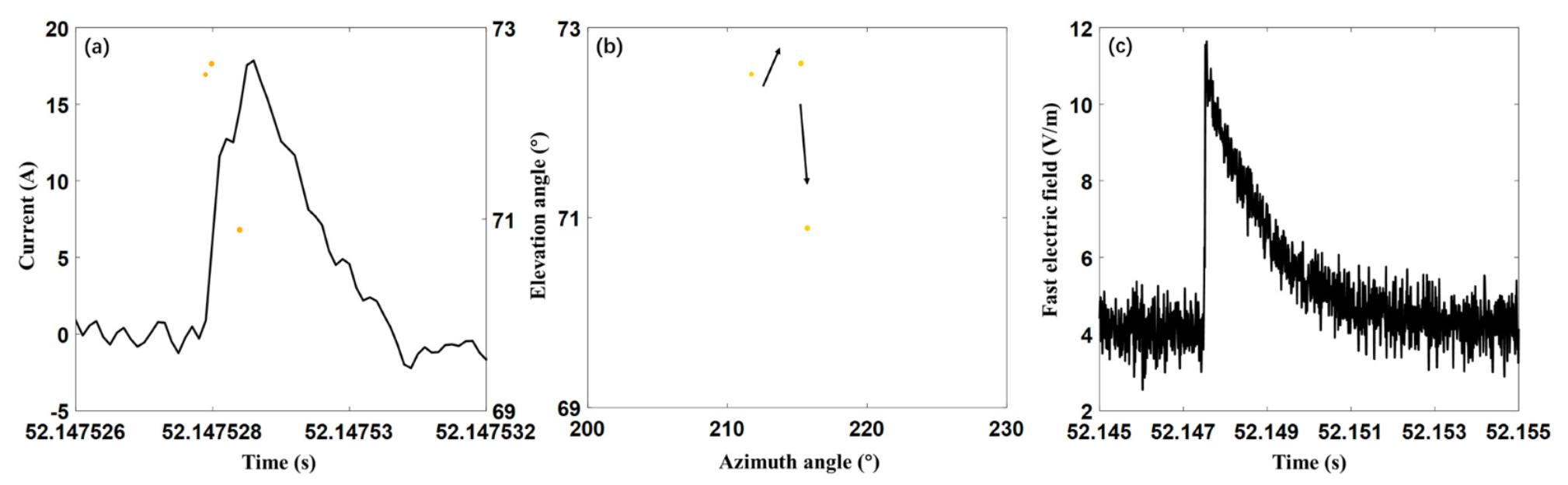
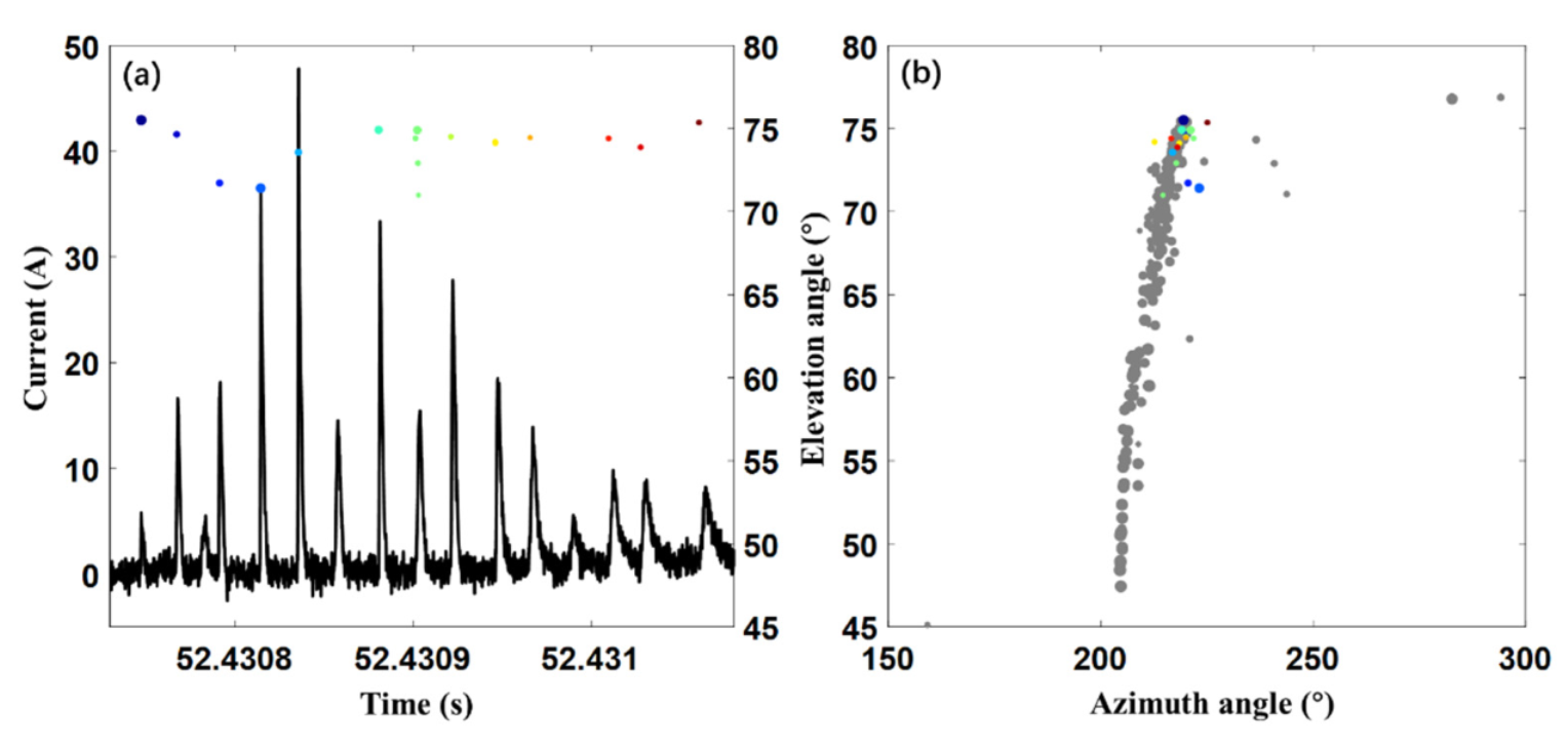
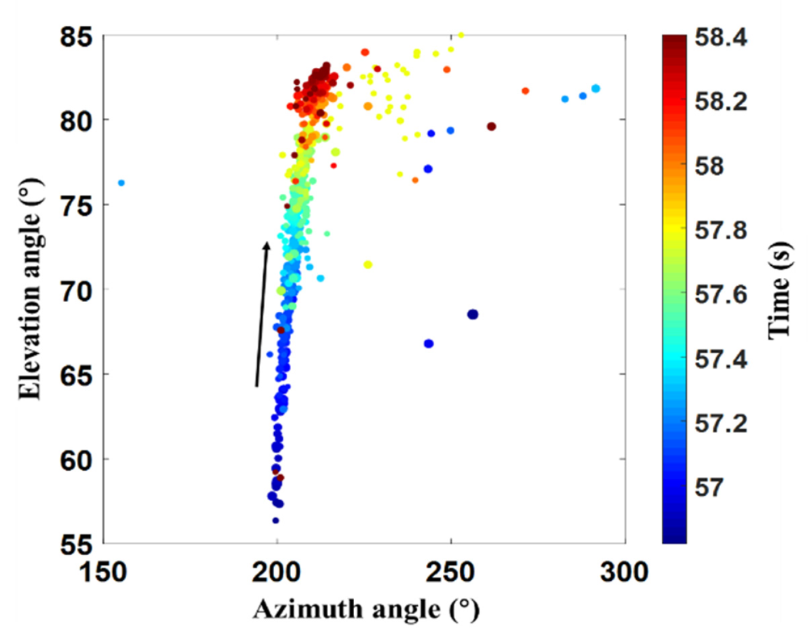
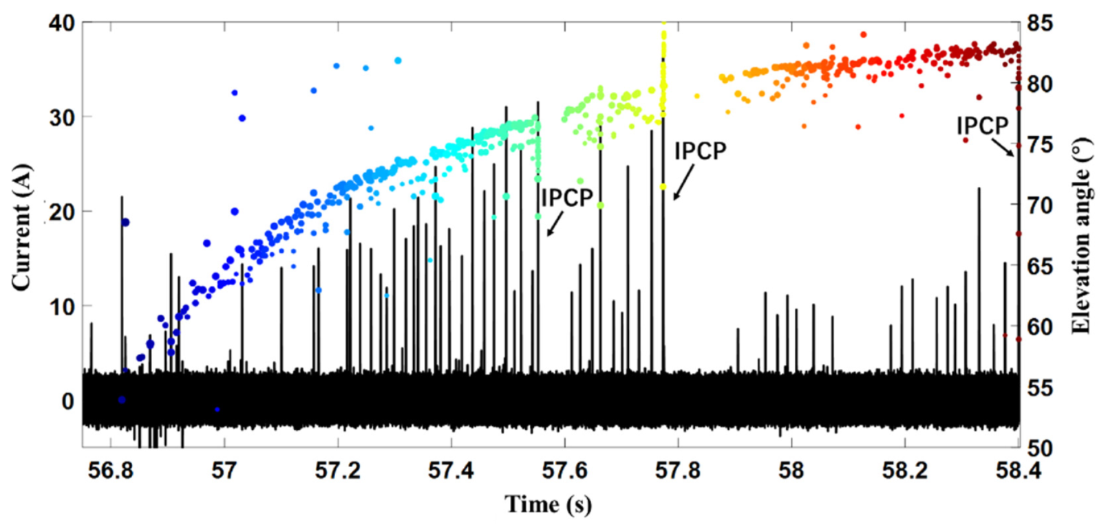
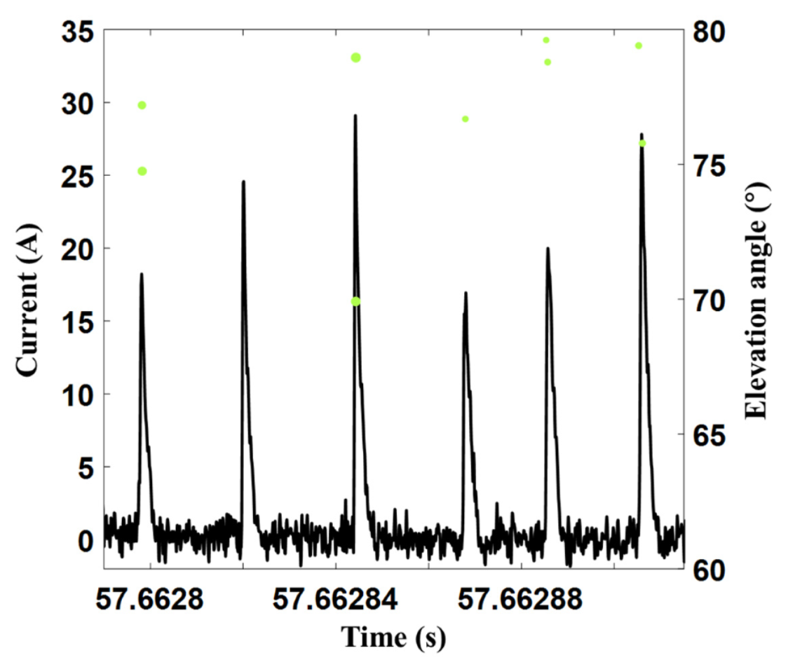
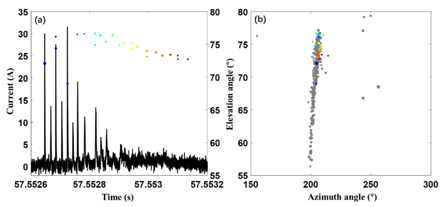
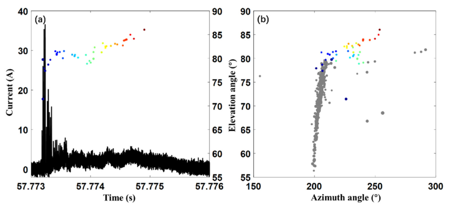
- The physical processed during the initial stage of the UPL of triggered lightning with a single initiation process and multiple initiation process were analyzed. When the rocket rose to a certain height, the CINTF began to detect the breakdown discharge process. The PCP signal, generated by a weak upward positive breakdown and a subsequent strong downward negative breakdown near the rising rocket tip, appeared in the current waveform. As the rocket continued to rise, the electric field near the rocket top increased, and PCP clusters appeared in the current waveform. At this time, the UPL began self-sustaining development, but the self-sustaining development disappeared quickly without continuous current. As the rocket continued to rise, the IPCP signal appeared, indicating that the UPL began self-sustaining development. The self-sustaining development after the IPCP could be short-term or continuous. After the short-term self-sustaining development, breakdown discharge could occur again near the rocket tip. It is also possible that the initial process could end completely and not develop into continuous self-sustaining development.
Author Contributions
Funding
Informed Consent Statement
Data Availability Statement
Acknowledgments
Conflicts of Interest
References
- Horii, K. Experiment of artificial lightning triggered with rocket. Mem. Fac. Eng. Nagoya Univ. 1982, 34, 77–112. [Google Scholar]
- Willett, J.C.; Davis, D.A.; Laroche, P. An experimental study of positive leaders initiating rocket-triggered lightning. Atmos. Res. 1999, 51, 189–219. [Google Scholar] [CrossRef]
- Zhang, Y.; Qian, Y.; Zhang, Y.; Lyu, W.; Zheng, D.; Chen, S. Discharge characteristics of upward positive leaders in initial stage of artificially triggered lightning. High Volt. Eng. 2017, 43, 1602–1608. (In Chinese) [Google Scholar]
- Chen, Z.; Zhang, Y.; Fan, Y.; Wang, J.; Zheng, D.; Fan, X.; Xu, L.; Lyu, W.; Zhang, Y. Evolution characteristics during initial stage of triggered lightning based on directly measured current. Atmosphere 2020, 11, 658. [Google Scholar] [CrossRef]
- Li, X.; Lu, G.; Jiang, R.; Zhang, H.; Fan, Y.; Shi, T.; Qie, X.; Zhang, Y.; Ren, H.; Zhang, C.; et al. On the transition from precursors to the initial upward positive leader in negative rocket-triggered lightning. J. Geophys. Res. Atmos. 2021, 126, e2020JD033926. [Google Scholar] [CrossRef]
- Shao, X.M.; Rhodes, C.T.; Holden, D.N. Rf radiation observations of positive cloud-to-ground flashes. J. Geophys. Res. 1999, 104, 9601–9608. [Google Scholar] [CrossRef]
- Ushio, T.-o.; Kawasaki, Z.-I.; Ohta, Y.; Matsuura, K. Broad band interferometric measurement of rocket triggered lightning in Japan. Geophys. Res. Lett. 1997, 24, 2769–2772. [Google Scholar] [CrossRef]
- Dong, W.; Liu, X.; Zhang, Y. Broadband interferometer observation of an artificially triggered lightning. Chin. Sci. Bull. 2001, 46, 427–432. (In Chinese) [Google Scholar] [CrossRef]
- Yoshida, S.; Biagi, C.J.; Rakov, V.A.; Hill, J.D.; Stapleton, M.V.; Jordan, D.M.; Uman, M.A.; Morimoto, T.; Ushio, T.; Kawasaki, Z.-I. Three-dimensional imaging of upward positive leaders in triggered lightning using VHF broadband digital interferometers. Geophys. Res. Lett. 2010, 37, L05805. [Google Scholar] [CrossRef]
- Edens, H.E.; Eack, K.B.; Eastvedt, E.M.; Trueblood, J.J.; Winn, W.P.; Krehbiel, P.R.; Aulich, G.D.; Hunyady, S.J.; Murray, W.C.; Rison, W.; et al. VHF lightning mapping observations of a triggered lightning flash. Geophys. Res. Lett. 2012, 39, L19807. [Google Scholar] [CrossRef]
- Hill, J.D.; Pilkey, J.; Uman, M.A.; Jordan, D.M.; Rison, W.; Krehbiel, P.R. Geometrical and electrical characteristics of the initial stage in Florida triggered lightning. Geophys. Res. Lett. 2012, 39, L09807. [Google Scholar] [CrossRef]
- Hill, J.D.; Pilkey, J.; Uman, M.A.; Jordan, D.M.; Rison, W.; Krebhiel, P.R.; Biggerstaff, M.I.; Hyland, P.; Blakeslee, R. Correlated lightning mapping array and radar observations of the initial stages of three sequentially triggered Florida lightning discharges. J. Geophys. Res. Atmos. 2013, 118, 8460–8481. [Google Scholar] [CrossRef]
- Sun, Z.; Qie, X.; Jiang, R.; Liu, M.; Wu, X.; Wang, Z.; Lu, G.; Zhang, H. Characteristics of a rocket-triggered lightning flash with large stroke number and the associated leader propagation. J. Geophys. Res. Atmos. 2014, 119, 13388–13399. [Google Scholar] [CrossRef]
- Zhang, Y.; Krehbiel, P.R.; Zhang, Y.; Lu, W.; Zheng, D.; Xu, L.; Huang, Z. Observations of the initial stage of a rocket-and-wire-triggered lightning discharge. Geophys. Res. Lett. 2017, 44, 4332–4340. [Google Scholar] [CrossRef]
- Zhang, Y.; Yang, S.; Lu, W.; Zheng, D.; Dong, W.; Li, B.; Chen, S.; Zhang, Y.; Chen, L. Experiments of artificially triggered lightning and its application in Conghua, Guangdong, China. Atmos. Res. 2014, 135–136, 330–343. [Google Scholar] [CrossRef]
- Zhang, Y.; Zhang, Y.J.; Zheng, D.; Lu, W. Characteristics and discharge processes of m events with large current in triggered lightning. Radio Sci. 2018, 53, 974–985. [Google Scholar] [CrossRef]
- Zhang, Y.; Zhang, Y.; Xie, M.; Zheng, D.; Lu, W.; Chen, S.; Yan, X. Characteristics and correlation of return stroke, M component and continuing current for triggered lightning. Electr. Power Syst. Res. 2016, 139, 10–15. [Google Scholar] [CrossRef]
- Zhang, Y.; Zhang, Y.; Li, C.; Lu, W.; Zheng, D. Simultaneous optical and electrical observations of “chaotic” leaders preceding subsequent return strokes. Atmos. Res. 2016, 170, 131–139. [Google Scholar] [CrossRef]
- Zhang, Y.; Zhang, Y.; Zheng, D.; Lu, W. Preliminary breakdown, following lightning discharge processes and lower positive charge region. Atmos. Res. 2015, 161–162, 52–56. [Google Scholar] [CrossRef]
- Zheng, D.; Zhang, Y.; Zhang, Y.; Lu, W.; Yan, X.; Chen, S.; Xu, L.; Huang, Z.; You, J.; Zhang, R.; et al. Characteristics of the initial stage and return stroke currents of rocket-triggered lightning flashes in southern China. J. Geophys. Res. Atmos. 2017, 122, 6431–6452. [Google Scholar] [CrossRef]
- Rison, W.; Krehbiel, P.R.; Stock, M.G.; Edens, H.E.; Shao, X.M.; Thomas, R.J.; Stanley, M.A.; Zhang, Y. Observations of narrow bipolar events reveal how lightning is initiated in thunderstorms. Nat. Commun. 2016, 7, 10721. [Google Scholar] [CrossRef] [PubMed] [Green Version]
- Shao, X.M.; Holden, D.N.; Rhodes, C.T. Broad band radio interferometry for lightning observations. Geophys. Res. Lett. 1996, 23, 1917–1920. [Google Scholar] [CrossRef]
- Rhodes, C.T.; Shao, X.M.; Krehbiel, P.R.; Thomas, R.J.; Hayenga, C.O. Observations of lightning phenomena using radio interferometry. J. Geophys. Res. 1994, 99, 13059–13082. [Google Scholar] [CrossRef] [Green Version]
- Shao, X.M.; Krehbiel, P.R.; Thomas, R.J.; Rison, W. Radio interferometer observations of cloud-to-ground lightning phenomena in Florida. J. Geophys. Res. 1995, 100, 2749–2783. [Google Scholar] [CrossRef]
- Biagi, C.J.; Jordan, D.M.; Uman, M.A.; Hill, J.D.; Beasley, W.H.; Howard, J. High-speed video observations of rocket-and-wire initiated lightning. Geophys. Res. Lett. 2009, 36, L15801. [Google Scholar] [CrossRef] [Green Version]
- Biagi, C.J.; Uman, M.A.; Hill, J.D.; Jordan, D.M. Observations of the initial, upward-propagating, positive leader steps in a rocket-and-wire triggered lightning discharge. Geophys. Res. Lett. 2011, 38, L24809. [Google Scholar] [CrossRef] [Green Version]
- Biagi, C.J.; Uman, M.A.; Hill, J.D.; Rakov, V.A.; Jordan, D.M. Transient current pulses in rocket-extended wires used to trigger lightning. J. Geophys. Res. 2012, 117, D07205. [Google Scholar] [CrossRef]
- Lalande, P.; Bondiou-Clergerie, A.; Laroche, P.; Eybert-Berard, A.; Berlandis, J.-P.; Bador, B.; Bonamy, A.; Uman, M.A.; Rakov, V.A. Leader properties determined with triggered lightning techniques. J. Geophys. Res. 1998, 103, 14109–14115. [Google Scholar] [CrossRef]
- Zhang, Y.; Chen, Z.; Wang, J.; Fan, Y.; Zheng, D.; Lyu, W.; Zhang, Y. Observation of the whole discharge process during a multi-stroke triggered lightning by continuous interferometer. J. Appl. Meteorol. Sci. 2020, 31, 197–212. (In Chinese) [Google Scholar]
- Abarca, S.F.; Corbosiero, K.L.; Galarneau, T.J., Jr. An evaluation of the Worldwide Lightning Location Network (WWLLN) using the National Lightning Detection Network (NLDN) as ground truth. J. Geophys. Res. 2010, 115, D18206. [Google Scholar] [CrossRef]
- Jiang, R.; Qie, X.; Wang, C.; Yang, J. Propagating features of upward positive leaders in the initial stage of rocket-triggered lightning. Atmos. Res. 2013, 129–130, 90–96. [Google Scholar] [CrossRef]
- Shao, X.-M.; Ho, C.; Meierbachtol, C.S.; Anderson, D. Lightning interferometric processing and uncertainty analysis for general noncoplanar antenna arrays. Earth Space Sci. Open Arch. 2021, 16. [Google Scholar]
- Scholten, O.; Hare, B.M.; Dwyer, J.; Sterpka, C.; Kolmašová, I.; Santolík, O.; Lán, R.; Uhlíř, L.; Buitink, S.; Corstanje, A.; et al. The initial stage of cloud lightning imaged in high-resolution. J. Geophys. Res. Atmos. 2021, 126, e2020JD033126. [Google Scholar] [CrossRef]
- Sterpka, C.; Dwyer, J.; Liu, N.; Hare, B.M.; Scholten, O.; Buitink, S.; Veen, S.T.; Nelles, A. The spontaneous nature of lightning initiation revealed. Geophys. Res. Lett. 2021, 48, e2021GL095511. [Google Scholar] [CrossRef]


Publisher’s Note: MDPI stays neutral with regard to jurisdictional claims in published maps and institutional affiliations. |
© 2022 by the authors. Licensee MDPI, Basel, Switzerland. This article is an open access article distributed under the terms and conditions of the Creative Commons Attribution (CC BY) license (https://creativecommons.org/licenses/by/4.0/).
Share and Cite
Chen, Z.; Zhang, Y.; Fan, Y.; Wang, J.; Lyu, W.; Zheng, D.; Pang, W. Close Observation of the Evolution Process during Initial Stage of Triggered Lightning Based on Continuous Interferometer. Remote Sens. 2022, 14, 863. https://0-doi-org.brum.beds.ac.uk/10.3390/rs14040863
Chen Z, Zhang Y, Fan Y, Wang J, Lyu W, Zheng D, Pang W. Close Observation of the Evolution Process during Initial Stage of Triggered Lightning Based on Continuous Interferometer. Remote Sensing. 2022; 14(4):863. https://0-doi-org.brum.beds.ac.uk/10.3390/rs14040863
Chicago/Turabian StyleChen, Zefang, Yang Zhang, Yanfeng Fan, Jingxuan Wang, Weitao Lyu, Dong Zheng, and Wenjing Pang. 2022. "Close Observation of the Evolution Process during Initial Stage of Triggered Lightning Based on Continuous Interferometer" Remote Sensing 14, no. 4: 863. https://0-doi-org.brum.beds.ac.uk/10.3390/rs14040863