Article

Modern Dryland Source-to-Sink System Segments and Coupling Relationships from Digital Elevation Model Analysis: A Case Study from the Mongolian Altai

1
Key Laboratory of Tectonics and Petroleum Resources, China University of Geosciences, Wuhan 430074, China
2
School of Earth Resources, China University of Geosciences, Wuhan 430074, China
*
Author to whom correspondence should be addressed.
Submission received: 18 January 2022 / Revised: 26 February 2022 / Accepted: 27 February 2022 / Published: 28 February 2022
(This article belongs to the Special Issue Remote Sensing of Dryland River Systems)

Abstract

:
Source-to-sink (S2S) systems have represented a major area of research in recent years; however, few modern S2S system analyses have been applied to typical dryland uplifts/mountains. A modern lacustrine sedimentary system is widely developed in the Great Lakes Basin of western Mongolia, and the Jargalant Nuruu in the Mongolian Altai is a suitable natural laboratory for modern dryland S2S system analysis. In this study, the multi-order S2S system of the Jargalant Nuruu was applied based on a digital elevation model (DEM) and Google Earth database analysis. The Jargalant Nuruu system is subdivided into three second-order sub-S2S systems of the eastern, western, and southern parts (S2S-E, S2S-W, and S2S-S, respectively) and 35 third-order sub-S2S systems (E1–E18, W1–W9, and S1–S8) according to the slope gradients, altitude, and hydrographic net of the Jargalant Nuruu recognized by DEM data, integrated with the quantitative recognition of the topographic drainage divide and structural patterns of the uplift margin. The three second-order S2S systems correspond to three various S2S system coupling models. The S2S-E is characterized by a steep slope gradient system (average 15.61°) with small-scale dominantly alluvial fan deposits (average 4.56 km2). S2S-W is represented by a gentle slope gradient system (average 10.24°) with large-scale dominated fan-shaped lobes (average 30.04 km2). S2S-S, in contrast, is a transformation zone system with transitional features between the two former types. Four major potential controlling factors for the difference in sub-S2S systems are summarized here, including tectonic activity, bedrock properties in the source area, morphology from source to sink, and climatic conditions. The landforms, sedimentary characteristics, and their differences in these sub-S2S systems are the result of the comprehensive influence and control of these multiple factors. This case study could serve as a useful reference for characterizing the sedimentary features of a modern or even ancient S2S system in other regions.

Graphical Abstract

1. Introduction

The source-to-sink (S2S) system (sediment routing system) is a complete analysis with sediment moved from the erosional engine of uplifts/mountains to its eventual site of deposition (Figure 1), and it has been a major area of research in recent years [1,2,3,4,5,6,7,8,9,10,11,12,13,14,15,16,17,18,19,20]. A principal aim of S2S system research is to better understand the dynamic surface processes and landscape evolution of sediment production, transport, and deposition [21,22] in different regions, including continental marginal basins [4,5,6,23], lacustrine basins [10,24,25,26], and glacial erosion or production [27,28,29,30,31,32]. Different segments of the S2S system generally represent distinct morphological components [24,33]. The landscapes of the segments from the catchment unit to the sediment fan, shaped by the influence of tectonics, climate, and base-level changes [1,6,7], are significant for the scale, dispersal pattern, and evolution of the sedimentary fans. As “the present is the key to the past”, modern geological case analysis is a useful tool to improve the comprehension of similar ancient systems (e.g., [10,24,26,33]). The study of modern S2S systems mainly starts with research on modern sedimentary environments and depicts the characteristics of sediments formed in different sedimentary environments [5,9,12]. The latest studies of modern S2S systems have mostly focused on marginal basins (e.g., [4,6,9]) and have discussed the geomorphological characteristics and relationships from mountains to sedimentary basins (e.g., [4,7,12]). Modern cases have displayed a comprehensive and global-scale database to characterize the interplay of modern S2S segments from continental catchments, shelves, and slopes and related submarine depositional fans on a time scale [10,24,33,34,35]. However, few modern S2S system analyses have been applied to typical dryland uplifts/mountains, and the quantitative relationships between the S2S segments of a complete uplift/mountain are still unclear. Moreover, the major influencing factors and generic coupling models of the various source morphologies, slope gradients, sediment transport pathway types, and scales of the depositional fans in the dryland uplift system [36,37,38,39,40] must also be further investigated.
A modern lacustrine sedimentary system is widely developed in the Great Lakes Basin of western Mongolia [33,41,42,43]. The Mongolian Altai region has experienced strong tectonic activity in the Cenozoic Era [42,44] and formed extensive Quaternary alluvial sediments [33,44]. This area is an important subject of modern continental sedimentary research. Numerous studies of provenance analysis in catchment drainage segments have attracted serious attention (e.g., [12]). These studies have focused mainly on the uplift area bedrock properties (e.g., [24]), drainage system units (e.g., [33]), and the ability to produce debris (e.g., [34]) that link the upstream and downstream segments, which is a significant basis for the anatomy of the sub-S2S systems. It is worth noting that there are obvious differences in the characteristics of “source”, “pathway”, and “sink” elements in various segments of the Jargalant Nuruu in the Mongolian Altai, and it is a suitable natural laboratory for modern dryland S2S system analysis.
Thus, in this study, we selected Jargalant Nuruu and its adjacent areas as our research target to characterize the features of a multi-order S2S system and their differences via a series of high-resolution digital elevation models (DEMs) and Google Earth databases. The main aims of this paper are (1) to establish the division of different sub-S2S systems in the Jargalant Nuruu and adjacent areas and further describe the morphological features and difference of the sub-S2S systems; (2) to illustrate the representative quantitative parameters from catchment drainages to alluvial fans; (3) to summarize the coupling models, processes, and relationships that correspond to various morphological types of the mountain; and (4) to discuss the potential controlling factors for the differences in the sub-S2S systems that developed in the same uplift S2S system. This study can serve as a reference for characterizing the sedimentary features of a modern S2S system in other similar morphological regions and can even be used for some deep-buried ancient uplift S2S systems via other database analyses (e.g., 3D-seismic data-based geomorphology and sedimentology).

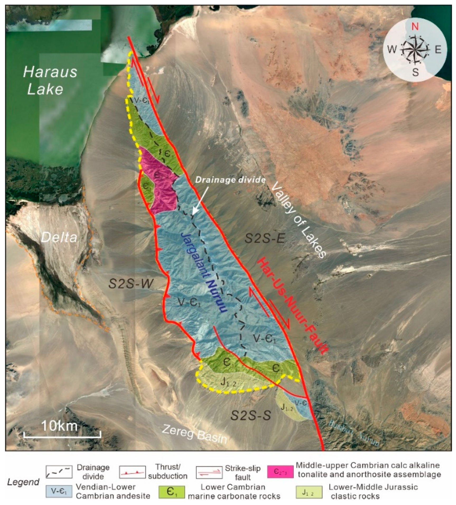
2. Geological Setting

The Altai Mountain range (western Mongolia), located in the western Central Asian orogenic belt and the northern Indian–Eurasian collision zone [41,44] (Figure 2a), is characterized by typical NNW–SSE-trending thrust faults perpendicular to the convergence direction (Figure 2b). Our study area, Jargalant Nuruu (47°1′55.95″–48°4′38.64″N, 92°15′10.40″–93°31′34.81″E), is an intrabasinal uplift or mountain that is located in northwestern Mongolia (Figure 2c) and is surrounded by the Zereg Basin, Valley of Lakes, Haraus Lake, Bumbat Nuruu, and the Mongolian Altai Range [33,41]. Jargalant Nuruu is approximately 62 km in length with a NW–SE trend and is 16 km in width, covering a total uplift area of 598.5 km2. The Zereg Basin is a typical intracontinental lake basin that is surrounded by the Altai Range to the southwest, covering an area of approximately 1100 km2, and there is a series of large-scale alluvial fans around the basin.
In the Mongolian Altai Range, many large-scale right-lateral strike-slip faults include a significant reverse component, which contributes to a series of N- to NW-trending long-term uplifts [41,44,45]. Uplifted peaks are up to 4500 m in elevation and generally show distinctively flat-topped features [44]. The active faults in this range mapped using satellite imagery can be key sources for some large-magnitude earthquakes [46,47,48,49,50]. Jargalant Nuruu and Bumbat Nuruu are controlled by the Har-Us-Nuur fault system [41,45] and exhibit two obvious separate uplifts trending NW–SE that are parallel to the fault zones. There is a low-topographic intersection zone between these two uplifts. In addition, affected by the compressive and torsional properties of strike-slip faults and regional compressive stress, some thrust faults are also present in the piedmont southwest of the Jargalant Nuruu.
The highest altitude of the Jargalant Nuruu is 3797 m. A large number of incised valleys with different scales are arranged en échelon along strike-slip faults (Figure 2c), which are mainly controlled by the structure, topography, and climate. In addition, a series of various-scale alluvial fans are present in the foothills and surrounding low-topographic areas, which are the main objects of this study.

3. Dataset and Methods

3.1. Jargalant Nuruu Modern S2S System Dataset

The datasets used for the Jargalant Nuruu modern S2S system analysis were mainly obtained from (1) satellite remote sensing of the Google Earth database and (2) the availability of global 30 m Shuttle Radar Topography Mission (SRTM) DEM data. High-quality satellite imagery from various perspectives of the study area was acquired from Google Earth software. To cover all of the Jargalant Nuruu, NASA’s (National Aeronautics and Space Administration) 30 m resolution SRTM DEM [51,52,53] was also applied for the S2S analysis. The SRTM GL1 Global 30 m Ellipsoidal (SRTM_GL1_Ellip) DEM data were obtained from OpenTopography, obtained by conversion from the orthometric version using the EGM96 geoid model [54]. These DEM data are characterized by an absolute height error of 6.5 m in 90% of western Mongolia and could be qualified for the relatively macro S2S analysis from the uplift source to the alluvial fans.
In addition, to support the quantitative recognition of catchment drainages and units of the Jargalant Nuruu, the acquired DEM data were applied in ArcGIS 10.2 software. The catchment partition of the modern uplift was performed by establishing DEM data and extracting a drainage system, which is useful for modern S2S characterization. The drainage network is composed of the potential flow paths in which the flow accumulations were greater than the raster calculator (1000 in this study). The topographic cross-sections of the transport pathways (e.g., incised valleys) were characterized in Global Mapper 21.0 software. The catchment area, topographic slope gradient, and length, and the fan area and length parameters of the S2S system in Table 1 were measured in ArcGIS software.

3.2. Multi-Order Modern S2S System Analysis Methods

First, the division of catchment units of the modern uplift S2S system is based mainly on the recognition of drainage divide, ridgeline, and slope gradient [10,24,55,56,57]. Integrated with the drainage network predicted results using ArcGIS software, the source area can be further divided into different-level drainage units (Figure 2). The whole Jargalant Nuruu can serve as a first-order S2S system. Then, the drainage divide and ridgelines in the uplift can divide the Jargalant Nuruu system into several second-order sub-S2S systems (e.g., S2S-W, S2S-E, and S2S-S) and a series of third-order sub-S2S systems (e.g., W1 to W9, E1 to E18, and S1 to S8).
Second, based on a comprehensive analysis of the drainage network analysis, flow path direction, and the position of the drainage system pour point (outfall), we can effectively depict the features of the transport pathways of the Jargalant Nuruu system. Then, the distribution range and boundary of the alluvial fans deposited in different sub-S2S systems can also be determined and integrated with high-quality satellite imagery identification.
Finally, the coupling mode diagrams of representative sub-S2S systems can be established. Based on the sub-S2S parameters from source to sink with different morphologies of various parts of the uplift, the scaling relationships between the catchment drainage units and alluvial fans can be discussed and summarized. Furthermore, relevant discussions of potential major controlling factors (e.g., tectonic activity difference, climate, bedrock types, morphology, and gradient) for the differences in these sub-S2S systems can also be had.

4. Results

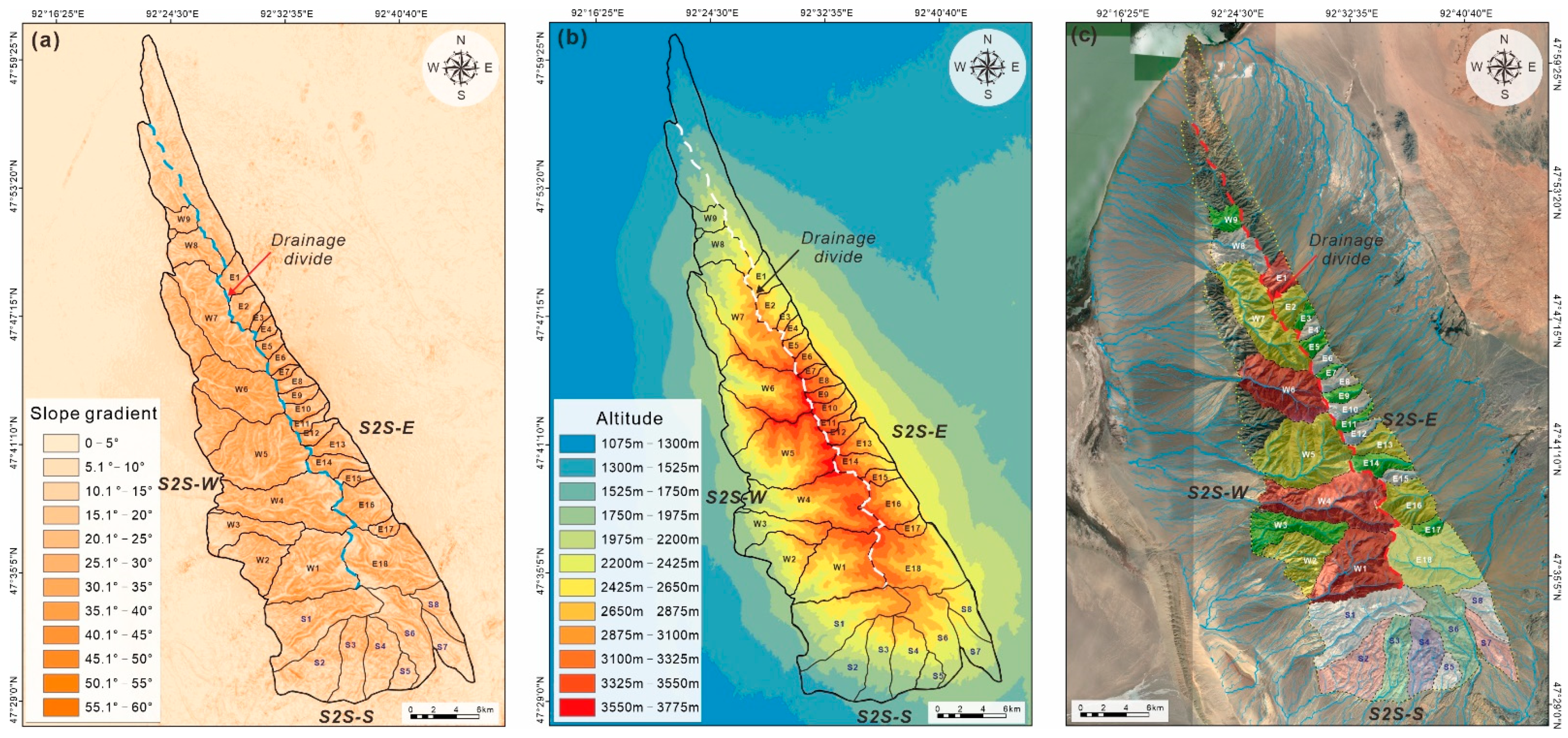
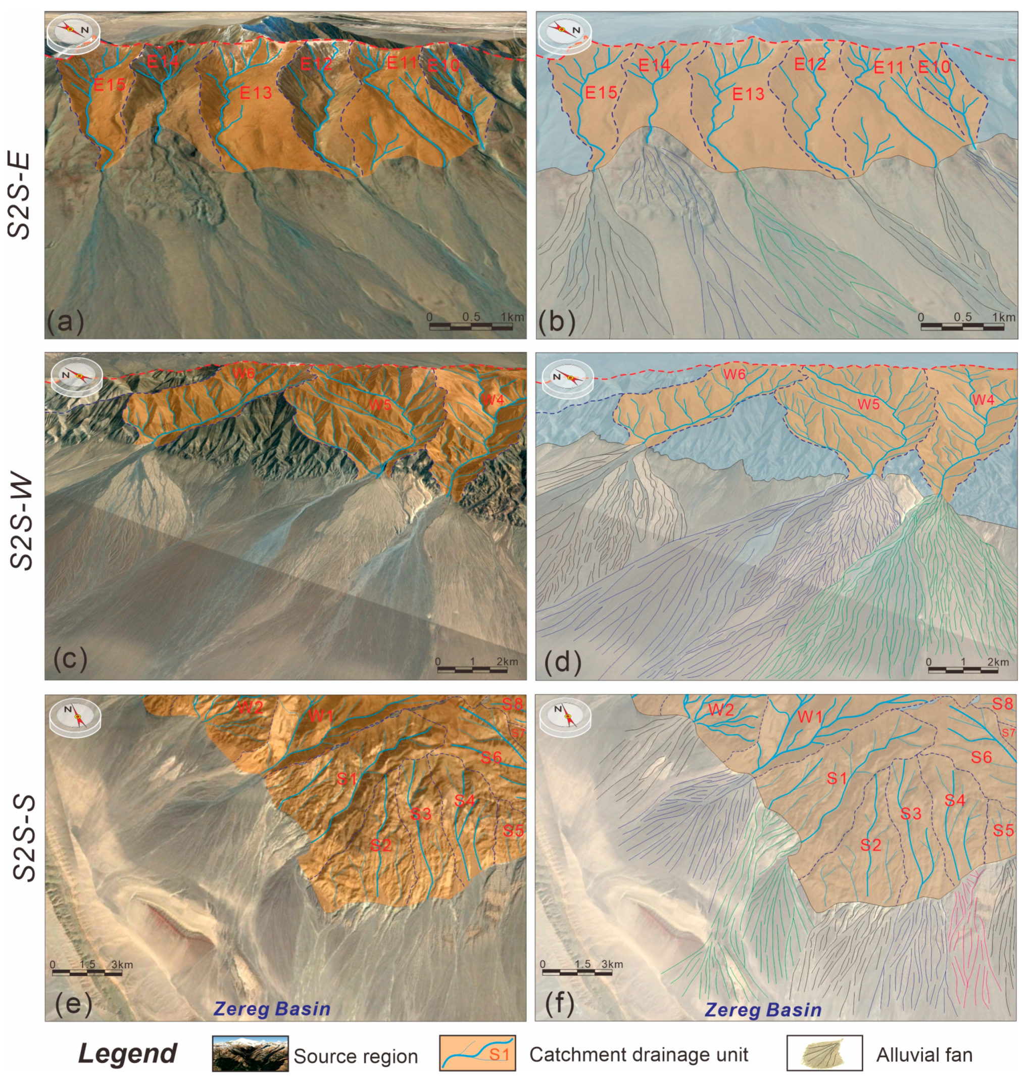
4.1. Source Catchment Drainage Segment Analysis

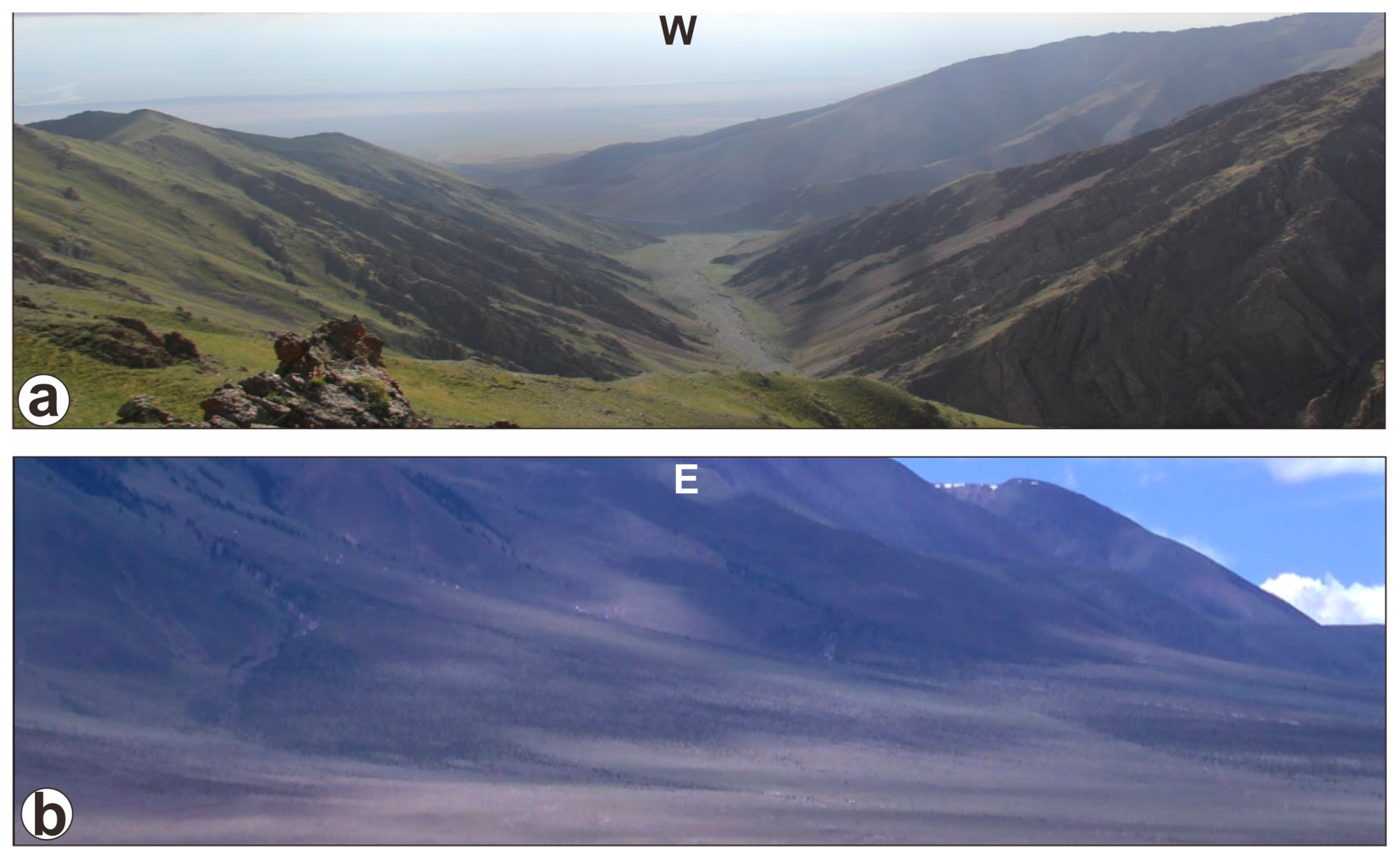
4.1.1. Bedrock Properties and Distribution Features

The Jargalant Nuruu S2S system is influenced by the NW–SE-trending Har-Us-Nuur strike-slip fault (Figure 3) in northwestern Mongolia. Most catchment drainage units along the NW–SE trend are covered by Vendian-lower Cambrian andesite (V-Є1) in the central and northernmost parts, lower Cambrian marine carbonate rocks (Є1) and middle-upper Cambrian calc-alkaline tonalite and anorthosite assemblages (Є2–3) in the mid-northern part, and small areas of lower Cambrian marine carbonate rocks (Є1) and lower-middle Jurassic clastic rocks (J1–2) in the southern part [58,59].

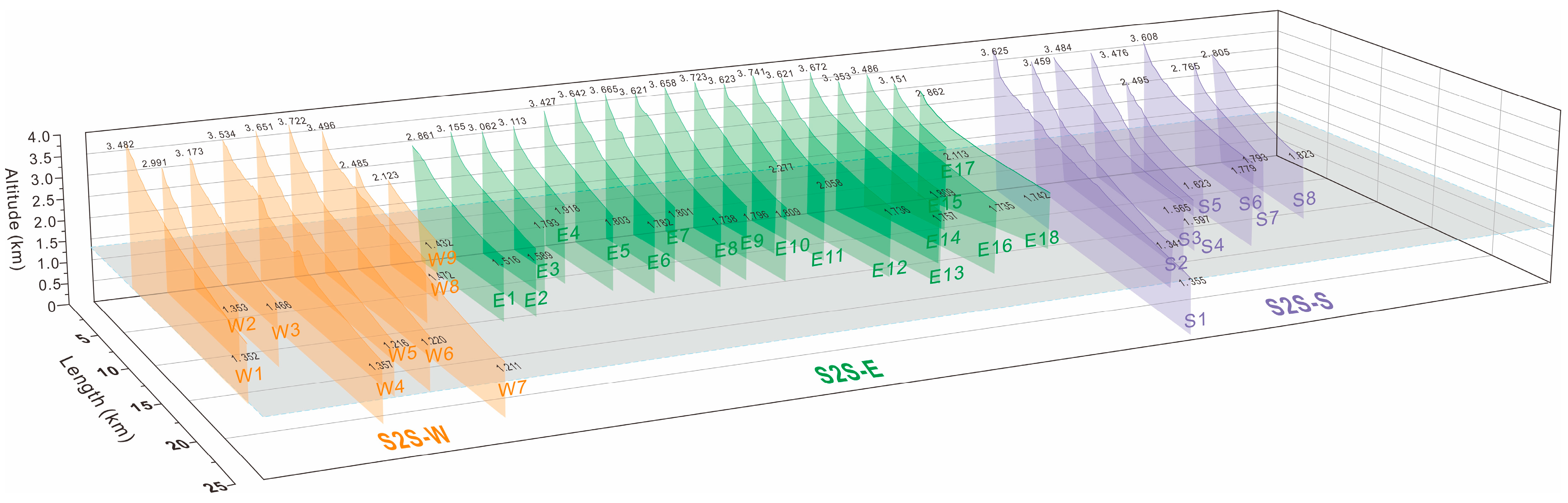
4.1.2. Multi-Order Catchment Unit Characteristics and Sub-S2S System Division

Due to physical and/or chemical weathering denudation, the provenance region of the Jargalant Nuruu provided sediments via a series of incised valleys into the surrounding depositional sink areas (Figure 2c). According to the slope gradients (Figure 4a), altitude (Figure 4b), and hydrographic net (Figure 4c) of the Jargalant Nuruu recognized by the DEM in ArcGIS, the boundaries of catchment drainage units are obtained (Figure 4). Then, integrated with the quantitative recognition of the topographic drainage divide and structural patterns of the uplift margin (Figure 4), the Jargalant Nuruu system is subdivided into three second-order sub-S2S systems in the eastern, western, and southern parts, namely, S2S-E, S2S-W, and S2S-S, respectively. It should be noted that the northern part of the Jargalant Nuruu consists of many small-scale subsystems and drainage units related to very small-scale alluvial fans, which are difficult to depict in detail. Therefore, in this study, S2S-E, S2S-W, and S2S-S are the major targets for the S2S system anatomy.
In addition, based on the landform (ridgelines and drainage divide) and drainage assemblages of the second-order sub-S2S systems (Figure 4), the Jargalant Nuruu system can be further divided into a series of third-order sub-S2S systems, including S2S-E, which can be subdivided into eighteen units (E1 to E18); S2S-W, which can be subdivided into nine units (W1 to W9); and S2S-S, which can be subdivided into eight units (S1 to S8). The morphological types of these sub-S2S systems have obvious differences among the three parts.
On the eastern side (S2S-E), the eighteen sub-S2S units are characterized by short, disjunct, small-scale drainage systems (Figure 4 and Figure 5). The slope gradients of E1 to E18 show that they are mainly developed within a steep slope with a gradient ranging from 12.23° to 22.15° (average 15.61°; Table 1). The drainage system areas of E1 to E18 are mostly less than 10 km2 (average 4.60 km2; Table 1), and the source lengths are mainly less than 5 km (average 3.49 km; Table 1). In addition, the cross-section of the sediment transport pathways of S2S-E show that the catchment units in this sub-S2S system consist of small-scale (less than 2 km in width) and relatively shallow (mostly less than 250 m in depth) morphologically incised valleys (Figure 6a). Overall, the morphology of S2S-E shows band-shaped and short-transport small-scale incised valleys with a series of corresponding catchment system units (Figure 4c).
On the western side (S2S-W), the nine sub-S2S units are characterized by long, conterminous, larger-scale drainage systems (Figure 4 and Figure 5). In contrast, the slope gradients of W1 to W9 indicate that these units developed within a relatively gentle slope with a gradient ranging from 8.05° to 12.62° (average 10.24°; Table 1). The drainage system areas of W1 to W9 are much larger than those of S2S-E and mostly range from 17.21 to 40.26 km2 (average 25.84 km2; Table 1). The source unit lengths are mainly larger than 8 km (average 8.03 km; Table 1). In addition, the cross-section (Figure 6a) of the sediment transport pathways of S2S-W shows that the drainage system units are represented by large-scale (3.0–5.6 km in width) and relatively deep-erosion (mostly larger than 250 m in depth) morphologically incised valleys (Figure 7a). Therefore, the western units developed more convergent topography than the eastern units, and the morphology of S2S-W mainly displayed a fan shape, gathering sediments and transporting them towards the outfall of the uplift margin (Figure 4c).
On the southern side (S2S-S), the eight sub-S2S units are located at the southern end of the Jargalant Nuruu and are characterized by medium-long, conterminous, various-scale drainage systems (Figure 4 and Figure 5). Compared with the S2S-E and S2S-W that developed at both sides of the drainage divide (Figure 4), the slope gradients of S1 to S8 are between the former two sides, with a gradient ranging from 11.23° to 13.58° (average 12.43°; Table 1). The areas of the S1 to S9 drainage units are also between the first two parts and mainly range from 13.68 to 34.25 km2 (average 18.34 km2; Table 1). In addition, the cross-section (Figure 6a) of the sediment transport pathways of S2S-S shows that the S1 to S9 drainage units are represented by medium-scale (2.0–4.3 km in width) and moderately eroded (approximately 200 m in depth) incised valleys (Figure 7a). Thus, the source region of the southern units is characterized by a transitional feature (such as a transformation zone system) between steep (S2S-E) and gentle (S2S-W) slopes and has developed a series of drainage systems with various distributions and sediment transport directions (Figure 2c and Figure 4c).

4.2. Sink-Sedimentary Response in the Depositional Area

Features of source region drainage units might have a significant influence on the sedimentary area, in which the topography controls the corresponding fan area scales, thicknesses, properties, shapes, and dispersal patterns. The depositional sink region of the Jargalant Nuruu could also be subdivided into 35 alluvial fans, which have good correspondence with the morphology of drainage units of S2S-E, S2S-W, and S2S-S (Figure 2c and Figure 8). These alluvial fans are derived from the drainage system units of the uplift source area, showing typical corresponding differences with the various catchment segments. The sedimentary characteristics of alluvial fan lobes developed in the three second-order sub-S2S systems in the Jargalant Nuruu and adjacent areas can be effectively identified through the outcrop/field and Google Earth databases. Detailed features of the sub-S2S system are described below.

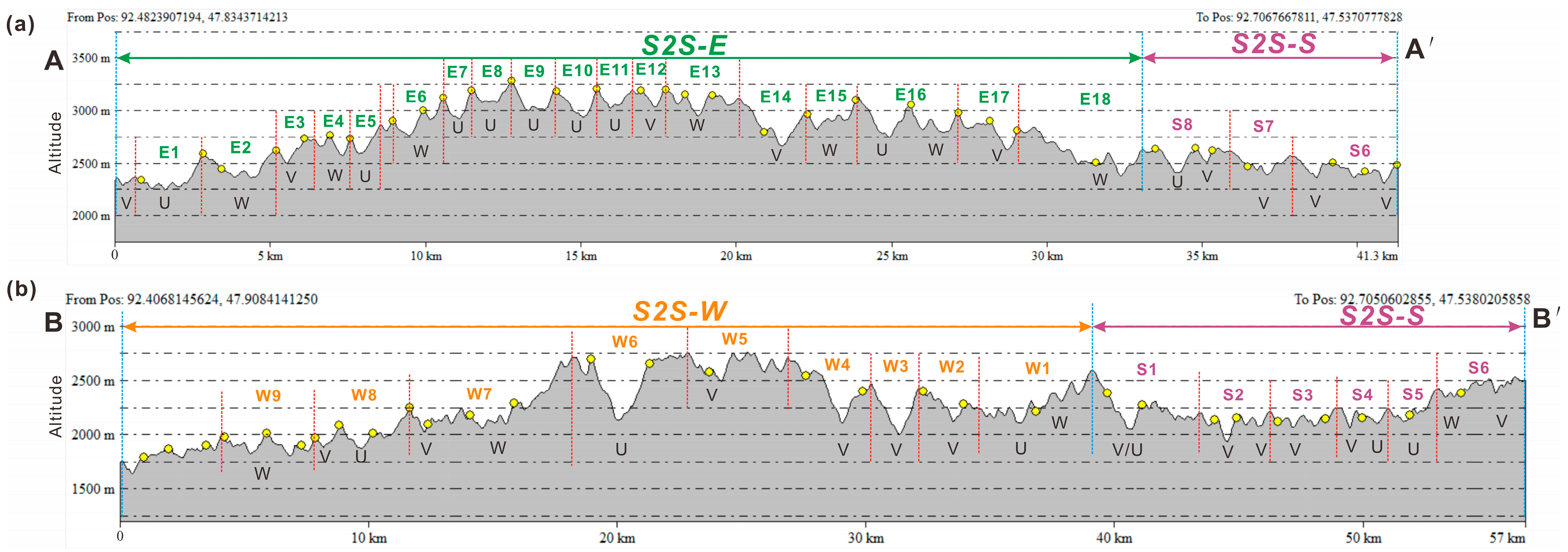
4.2.1. Eastern Source-to-Sink System (S2S-E)

The depositional sink area (E1 to E18) of S2S-E can be identified as a series of miniature, long strip-shaped alluvial fan lobes (Figure 2c and Figure 8a,b), which have a one-to-one relationship with the source drainage units. These fans developed in S2S-E show relatively small areas ranging from 0.78 to 20.32 km2 (average 4.56 km2; Table 1) and short fan lengths ranging mainly from 1.47 to 6.87 km (average 3.61 km; Table 1). In addition, the ratio of areas of the source drainage unit and the sink depositional fans exhibits a relatively good correspondence (average 1:0.95; Table 1), indicating that the topography of this steep slope depositional system has great constraints on the corresponding fan distribution and dispersal pattern.

4.2.2. Western Source-to-Sink System (S2S-W)

The sedimentary features of S2S-W from W1 to W9 show a series of larger-scale and typical fan-shaped alluvial lobes (Figure 2c and Figure 8c,d) than those of S2S-E, which also have a well-corresponding relationship with the drainage systems of the source segment. Based on the high-resolution Google Earth images (Figure 8d) and field photographs (Figure 7b), we can easily identify the distributary channel system that developed in these fans in S2S-W, especially in the W4 to W6 units. In general, the fans in S2S-W exhibit large areas ranging mainly from 13.67 to 56.78 km2 (average 30.04 km2; Table 1) and much larger fan lengths ranging from 6.87 to 12.35 km (average 8.18 km; Table 1). The detailed parameters (Table 1) show that the alluvial fans formed within catchment drainage units with a convergent morphology might have larger-scale fan deposits, regardless of area or length. The ratio of areas of the source drainage unit and the depositional fans (average 1:16; Table 1) also exhibits a similar phenomenon: the topographic feature of this relatively gentle slope system has good constraints on the related shapes and scales of alluvial fans.

4.2.3. Southern Source-to-Sink System (S2S-S)

In contrast, S2S-S is located on the southern edge of the Jargalant Nuruu and the transformation zone between the Jargalant Nuruu and Bumbat Nuruu, showing typically different characteristics compared with the S2S-E and S2S-W units (Figure 2c and Figure 8e,f). It is characterized by a middle scale in area (average 20.08 km2; Table 1) and length (average 9.32 km; Table 1) of the alluvial fans between the former two sub-S2S systems above. In addition, the shapes of alluvial fans and the ratio (drainage unit area/alluvial fan area; average 1:09; Table 1) also exhibit a transitional feature with a combination of a long strip shape and fan shape from source to sink (Figure 8f), indicating that S2S-S can be a transition type between the eastern and western systems that developed on the two sides of the drainage divide.

5. Discussion

5.1. Source-to-Sink System Coupling Models

Sediment distribution in a source-to-sink (S2S) system corresponds to linked segments of sediment routing pathways from areas of erosion in the hinterland to areas of deposition in the basin, often embracing the dynamic processes and feedback mechanisms between the autogenic and allogenic forcing conditions that govern sediment dispersal in erosional–depositional systems [1,2,3,5,8,24]. Source-to-sink analysis in a dryland uplift system, however, needs to be implemented, including the characteristics of bedrock and catchment units, sediment transport pathway types and sizes, sedimentary architecture and fluxes, and the proportional range between source-to-sink segments [4,5,9,36,37,38,39,40]. The major differences in dryland S2S systems are generally affected by landforms and boundary styles in the form of uplift, including (1) source regions—these three systems are mainly supplied by local material sources with various topographic features and drainage system areas; (2) pathways—incised valleys and faulted troughs, the major styles with various scales in different subsystems; and (3) sedimentary systems—alluvial deposits under the control of temporary water flow are mainly developed, showing banded or fan-shaped distributions and independent/overlapping distributary channels.
According to the geomorphological features and internal relationships of source region drainage units, sediment transport pathways, and the sink area alluvial fan dispersal patterns, three different source-to-sink system coupling models of the Jargalant Nuruu and adjacent areas, including the steep slope, gentle slope, and transformation zone systems, can be summarized (Figure 9 and Figure 10). All quantitative parameters of the multi-order source-to-sink system of the Jargalant Nuruu are shown in Table 1.

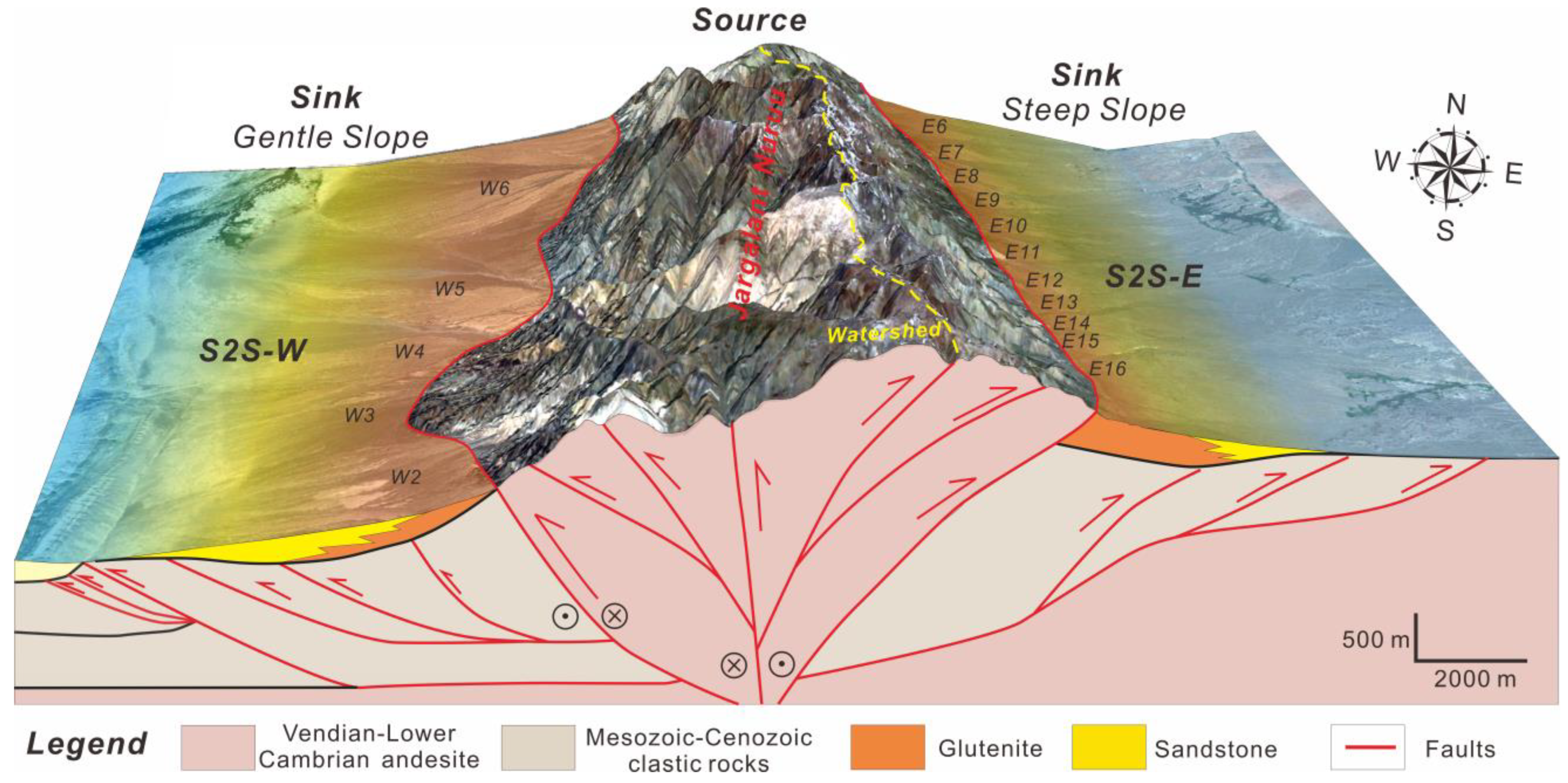
5.1.1. Steep Slope System Coupled Model of S2S-E

The eastern Jargalant Nuruu is characterized by a relatively steep slope (average 15.61°) with a vertical elevation of approximately 2000 m from source to sink (Figure 5), belonging to the zone with the largest slope in this study area. The steep slope system of S2S-E is located mainly in the northern part of the Har-Us-Nuur fault system with an arc-shaped and relatively steep-angle fault plane (34.2°) [44,47]. Sediments are derived mainly from the Vendian-lower Cambrian andesite (V-Є1) bedrock (Figure 3), which is favorable for the generation of clastic rocks [24,34]. The key feature of this sub-S2S system is its linear source supply mode along the thrust fault, in which sediments are transported through multiple (≥18) small-scale incised valleys (Figure 6a) that developed along the fault section and finally form a series of small-scale, glutenite-dominated alluvial fan lobes (Figure 9). The alluvial fans of units E1 to E18 accumulated near the corresponding drainage outfalls (Figure 8b and Figure 9). In addition, it is worth noting that the piedmont alluvial fan system in the sink area in arid and semi-arid environments is characterized by long strip- and belt-shaped distributions and mutual separation.

5.1.2. Gentle Slope System Coupled Model of S2S-W

Western Jargalant Nuruu, however, is characterized by a relatively gentle slope (average 10.24°) with a smaller vertical elevation of approximately 1200 m from source to sink (Figure 5). The gentle slope system of S2S-W is related to a branch fault of the Har-Us-Nuur fault system (Figure 9) [44,47], which is represented by irregular fault section features and gentle slopes (<7.0°). Similar to S2S-E, sediments of this system in the west are also mainly derived from the Vendian-lower Cambrian andesite (V-Є1) bedrock (Figure 3) in the arid and semi-arid environments [48,49], but the drainage system unit areas of W1 to W9 generally show a much larger scale than those on the eastern steep slope. The representative feature of this model is that a series of large-scale fan-shaped and sandstone-dominated alluvial lobes developed on the margin of the uplift and have good correspondence with the drainage systems and sediment transport pathways.

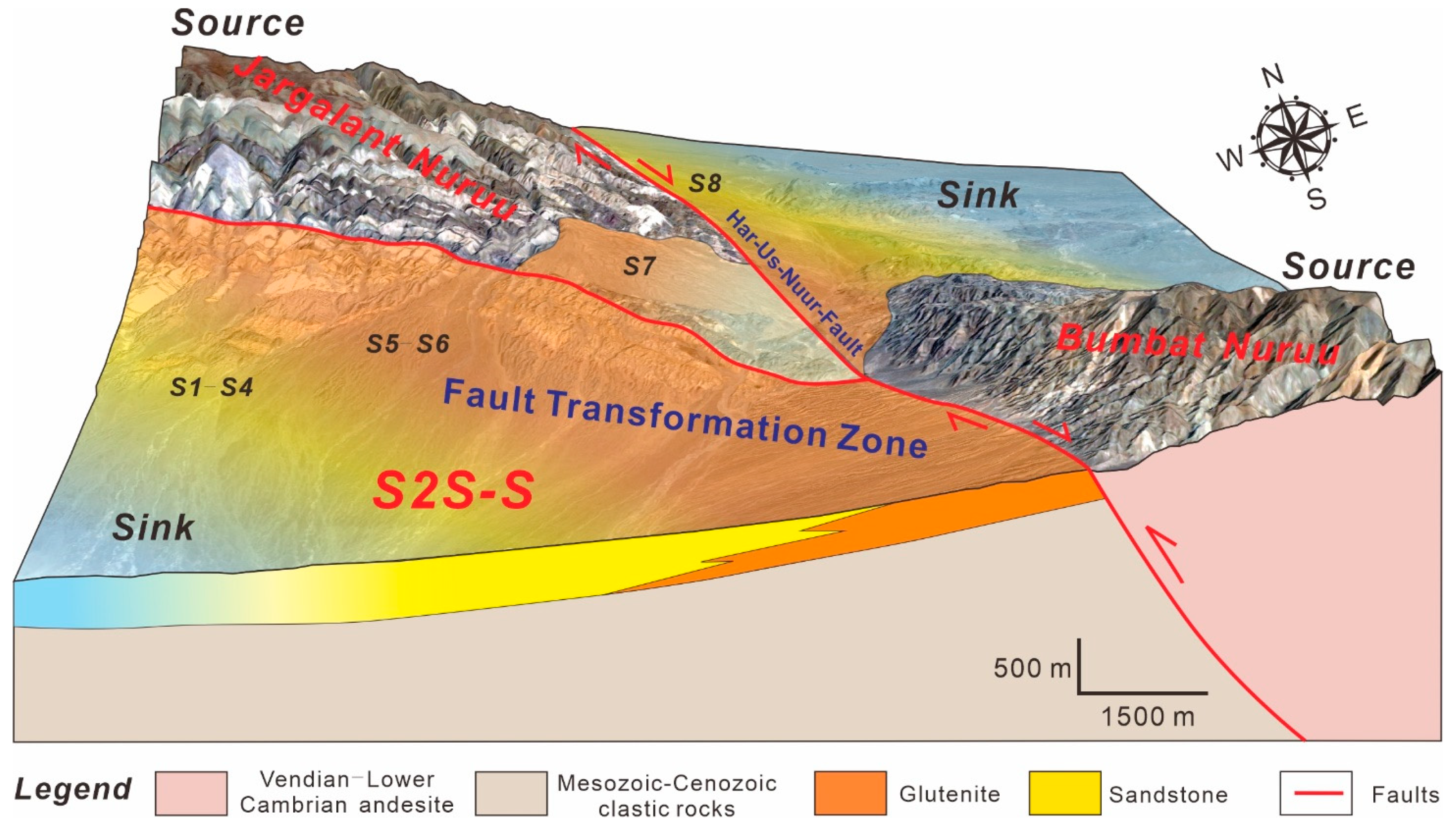
5.1.3. Transformation Zone System Coupled Model of S2S-S

S2S-S is a typical transformation zone system located between the Jargalant Nuruu and Bumbat Nuruu, exhibiting a medium-type coupling model of the former (Figure 10). Vertical elevation from source to sink in this sub-S2S unit ranges mainly from 1500 to 2000 m (Figure 3), having a relatively medium-angle slope (average 12.43°). It is developed at the intersection of the main and branch faults of the Har-Us-Nuur fault system. Different from S2S-E and S2S-W, sediments of this system in the south are mainly derived from lower Cambrian marine carbonate rocks (Є1) and lower-middle Jurassic clastic rocks (J1–2). A significant feature of this transformation zone system coupling model is that there are two obvious provenance regions (southern Jargalant Nuruu and northern Bumbat Nuruu) that transport and accumulate sediments to the low-lying area of the transition zone (Figure 10). A series of long strip-shaped and fan-shaped alluvial lobes dominated by glutenite and sandstone can be clearly identified in the transformation zone. In addition, the fan scale in the area of the western transition zone (Є1 carbonate bedrock and J1–2 clastic bedrock) is much larger than that in the eastern transition zone (Є1 carbonate bedrock), indicating that the source-to-sink bedrock, topography, and drainage features of S2S-E and S2S-W might have important impacts on the sediment dispersal patterns of the transformation zone in S2S-S.

5.2. Reliability of Multi-Order Sub-S2S Systems Analysis

Due to long-term denudation, the geomorphic features of uplift may change to a certain extent. The multi-order S2S system analysis for the modern uplift based on DEM data and Google Earth images generally may have a query as to whether the results are reliable. In this study, the second-order sub-S2S systems (S2S-E, S2S-W, and S2S-S) and the third-order sub-S2S systems (E1–E18, W1–W9, and S1–S8) of the Jargalant Nuruu are identified and subdivided according to the quantitative characterization of the topographic drainage divide and various drainage unit patterns of the uplift (Figure 4), which have a good corresponding relationship with the alluvial fan type and scale of each sub-S2S system. This also suggests that the results of these multi-order sub-S2S systems are reasonable.
In addition, the geomorphological scaling patterns of the third-order sub-S2S parameters from source to sink to some extent can be used to confirm the effectiveness of our results and methods and can even further discuss the scaling relationships between the catchment drainage units and alluvial fans. According to the representative morphological elements (Table 1), such as the catchment area, fan area, slope gradient, and length of the longest channel, we can obtain the correlation between different parameters (Figure 11). The four scatter charts show that the fan area, catchment area, and length of the longest channel have a positive correlation between them (Figure 11a,b,d). However, the slope gradient shows a negative correlation with the depositional fan area (Figure 11c). In addition, the geomorphological scaling patterns shown in this study also have similar features to those in continental margins [5,6], fluvial systems [12], or ancient uplift systems [10,33], indicating that the characterization results and methodology used in this modern uplift research are reliable. Even though the parameters of these sub-S2S systems might have a certain error due to the restriction of element calculations in Google Earth software, the understanding obtained from our research can be popularized and applied in more different geological backgrounds.

5.3. Potential Controlling Factors for the Diversity of Sub-S2S Systems

The potential controlling factors for the difference in sub-S2S systems in the study area mainly include tectonic activity, bedrock properties in the source area, morphology from source to sink, and climatic conditions.

5.3.1. Tectonic Activity

Tectonism, especially synsedimentary fault activity, plays an important role in controlling the landform, sediment transport path, and final sedimentary filling and distribution of the S2S processes from the whole provenance area to the adjacent lake basins [2,5,12,44]. Tectonic activities can directly affect the uplift scale and area, lead to different denudation capacities of the source area, affect the source supply capacity, produce different sediment supply rates, and even control the scale of the accommodation space of the surrounding basins [3,60].
The difference in tectonic action will control the geomorphic difference in the source area, such as the slope gradient and slope length of the terrain, and further affect the development and scale of the drainage systems [34]. The source areas affected by strong tectonic activities, such as S2S-W, experienced strong erosion, developed a series of large-scale incised valleys and relatively large accommodation spaces, and formed some large-scale alluvial fans at the outlet (Figure 9). In areas with weak tectonic activity, such as the northern Jargalant Nuruu and eastern S2S-S, however, the erosion of drainage systems is generally weak, with surface sheet flow and very small-scale fan lobes (Figure 2c). The weak tectonic source areas are generally characterized by excessive filling, and the denuded clastic products often cover the stable surface of the source area without obvious transportation or migration. Thus, in this study, the sediment supply in the northern Jargalant Nuruu is weak and can be ignored.

5.3.2. Bedrock Properties

Lacustrine rift basins are often characterized by diverse bedrock developing different boundary styles, and the bedrock properties can affect the morphology, drainage assemblages, and weathering of catchments. Previous studies [24,34] have indicated that bedrock properties could effectively affect the weathering and denudation rate of the source region and then further control the morphometry and catchment drainage system units to some extent. Silicate bedrock, including metamorphic and/or igneous bedrock, generally has the features of complicated landforms, large-scale elevation variations in slopes, and the development of multi-order drainage systems with intersecting deposits [24]. Silicate bedrock commonly undergoes typical physical weathering and develops relatively thick, large-scale, and overlapping alluvial fan lobes on the uplift edge with a high depositional rate. Carbonate bedrock, in contrast, is mainly subjected to chemical weathering and denudation, forming chemically dissolved sediments and relatively thin, small-scale isolated fans with a low depositional rate.
In this study, S2S-E, S2S-W, and western S2S-S (Figure 3) are mainly characterized by the Vendian-lower Cambrian andesite (V-Є1) bedrock and lower-middle Jurassic clastic rocks (J1–2), which are conducive to the formation of a large amount of debris after weathering, leaching, and denudation. Therefore, a series of large-scale alluvial fan-shaped lobes can be identified in the large-area catchment drainage systems (e.g., E1, E2, E13, E16, E18, W1, W2, W4–W7, and S1–S4). In other third-order sub-S2S systems in these regions, despite the advantageous setting of bedrock properties, they still only developed some small- to medium-scale lobes due to the limitation of the catchment area. In contrast, the northern Jargalant Nuruu and eastern S2S-S (Figure 3) are characterized by lower Cambrian marine carbonate rocks (Є1) and middle-upper Cambrian calc-alkaline tonalite and anorthosite assemblages (Є2–3), which might not be conducive to the formation of a large amount of clastic material. Thus, integrated with the weak tectonic activity in these two regions, we can only identify some small-scale, long strip-shaped fan lobes.

5.3.3. Geomorphology from Source to Sink

The morphology and topographic features of the uplift S2S system from the provenance region to the depositional area also play a significant role in the development of various types and scales of alluvial fan lobes [10,33,34]. The geomorphology here refers mainly to the slope gradient, vertical elevation from source to sink, sub-S2S system boundary type, catchment drainage system scale, and sediment transport path type and scale.
Under the comprehensive influence of regional tectonic activity and bedrock properties, in this study, the three second-order sub-S2S systems (S2S-E, S2S-W, and S2S-S) show obviously different geomorphological characteristics (i.e., Figure 8). In summary, S2S-E is characterized by a steep slope gradient system (average 15.61°) and large vertical elevation from source to sink (>2000 m) with small-scale dominated sediment transport pathways and alluvial fan deposits. S2S-W is represented by a relatively gentle slope gradient system (average 10.24°) and a smaller vertical elevation of approximately 1200 m with large-scale dominated sediment transport pathways and fan-shaped lobes. S2S-S, in contrast, is a transition type between the former two systems, regardless of the slope gradient, vertical elevation, catchment drainage scale, or corresponding alluvial fans. These features were also confirmed by the results of the morphological scaling relationships of the modern Jargalant Nuruu system (Figure 11). In addition, it is worth noting that the scale of catchment drainage units can affect the sediment transport pathways and sediment dispersal patterns, in which the large-scale catchment units are generally related to the most favorable large-scale fan lobes, while the small-scale catchment units might correspond to the local small-scale fan deposits.

5.3.4. Climatic Conditions

Climate refers to the average course or condition of the weather at a place usually over a period of years as exhibited by temperature, wind velocity, humidity, and precipitation [61], which has an important impact on the evolution of modern uplift S2S system analysis. The uplifted landforms are highly sensitive to temperature and precipitation and are excellent indicators of past climate change [31,32]. The interaction and alternating intensity of climatic trend factors since the Quaternary in the study area have affected the change in material erosion and accumulation rate and control the vegetation composition and density, desertification process, lake level, and glacier distribution [41,45,48].
Due to its mid-latitude location and the influence of regional topography and mountains, the study area is affected by various circulation systems [62], especially in winter, and the Siberian high-pressure system forms a cold and dry climate environment. Temperature and humidity are very important for influencing sediment supply conditions in climate control. Under the influence of extreme continental arid and semi-arid climatic conditions in western Mongolia [58,59], small changes in temperature and precipitation caused considerable environmental changes during the Holocene. The climate in the study area changed from a cold and dry type in the Late Pleistocene to a relatively warm and humid type in the early Holocene [41]. With an increase in water flow caused by an increase in interglacial temperature, glacial melting, and atmospheric precipitation, the early glacial erosion products were transported by the drainage system and pathways and formed a large-scale alluvial fan system or large-scale piedmont accumulation downstream (Figure 2c and Figure 8). Since the middle Holocene, the influence of the westerly belt increased, temperature and precipitation began to decline, and vegetation degraded to a certain extent, in which it was easy to form alluvial fan deposits under the control of mountain torrents. In addition, the deposition rate of alluvial fans was promoted during the transition from a cold and dry glacial period to a relatively warm and humid interglacial period [63].
Therefore, under the influences of regional tectonic activities and climatic conditions, the differences in each second-order S2S in a dryland uplift were formed in different geomorphological units through different weathering and denudation of different bedrock types. The landforms, sedimentary characteristics, and differences in the sub-S2S systems are results of the comprehensive influence and control of multiple factors discussed above.

6. Conclusions

Multi-order source-to-sink (S2S) system analysis plays a significant role in coupling relationship studies of various segments from the provenance region to the depositional area. In this study, a detailed characterization of the modern dryland S2S system of the Jargalant Nuruu and adjacent areas was applied to reveal the features and differences in the sub-S2S systems using a series of remote sensing images and topographic cross-sections. The major conclusions are presented as follows:
(i) The Jargalant Nuruu system is subdivided into three second-order S2S systems (S2S-E, S2S-W, and S2S-S) and 35 third-order S2S systems (E1–E18, W1–W9, and S1–S8) based on the quantitative recognition of the topographic drainage divide and structural patterns of the uplift margin. The major differences in these sub-S2S systems are significantly affected by the morphology and boundary style in the form of banded uplift.
(ii) The three second-order S2S systems correspond to three various source-to-sink system coupling models. S2S-E is characterized by a steep slope gradient system and large vertical elevation from source to sink with dominantly small-scale alluvial fan deposits. S2S-W is represented by a gentle slope gradient system with large-scale dominant sediment transport pathways and fan-shaped lobes. S2S-S, in contrast, is a transition type of transformation zone system between the former two systems, regardless of the slope gradient, vertical elevation, catchment drainage scale, or alluvial fans. The geomorphological scaling patterns of the third-order sub-S2S parameters from source to sink were applied to confirm the reliability and effectiveness of the results and methods used in this research.
(iii) The potential controlling factors for the difference in the modern dryland multi-order S2S system mainly include tectonic activity, bedrock properties in the source area, landforms from source to sink, and climatic conditions. The sedimentary characteristics and their differences in these sub-S2S systems are the comprehensive result of multiple factors with different geomorphological units through different weathering and denudation patterns of different bedrock types. The methodology in this study can serve as an effective reference for characterizing the sedimentary features of a modern S2S system in other similar morphological regions.

Author Contributions

Conceptualization, investigation, writing—original draft preparation, review, validation, and editing, Z.Z.; methodology, formal analysis, resources, and data curation, H.Z. All authors have read and agreed to the published version of the manuscript.

Funding

This research was funded by the China National Postdoctoral Program for Innovative Talents (grant No. BX20200310), the China Postdoctoral Science Foundation (grant No. 2020M682522), and research funding for postdoctoral innovation in Hubei Province (grant No. 257236). This research was also funded by the National Natural Science Foundation of China (grant No. 42172127, grant No. 41872149).

Institutional Review Board Statement

Not applicable.

Informed Consent Statement

Not applicable.

Acknowledgments

Thanks are given to Qianghu Liu, Zelong Ji, and Zhiyao Li from China University of Geosciences, Wuhan, for their help in the DEM data analysis and constructive suggestions for the multi-order S2S analysis. Special thanks to Zelong Ji; the discussion with him played a significant role in the improvement of our research and article writing. The constructive suggestions of the anonymous reviewers are gratefully acknowledged.

Conflicts of Interest

The authors declare no conflict of interest.

References

  1. Allen, P.A. From landscapes into geological history. Nature 2008, 451, 274–276. [Google Scholar] [CrossRef] [PubMed] [Green Version]
  2. Allen, P.A. Time scales of tectonic landscapes and their sediment routing systems. Geo. Soc. Lond. Spec. Pub. 2008, 296, 7–28. [Google Scholar] [CrossRef]
  3. Allen, P.A.; Densmore, A.L. Sediment flux from an uplifting fault block. Basin Res. 2000, 12, 367–380. [Google Scholar] [CrossRef]
  4. Martinsen, O.J.; Sømme, T.O.; Thurmond, J.B.; Helland-Hansen, W.; Lunt, I. Source-to-sink systems on passive margins: Theory and practice with an example from the Norwegian continental margin. Geol. Soc. Lond. Pet. Geol. Conf. Ser. 2011, 7, 913–920. [Google Scholar] [CrossRef]
  5. Sømme, T.O.; Helland-Hansen, W.; Martinsen, O.J.; Thurmond, J.B. Relationships between morphological and sedimentological parameters in source-to-sink systems: A basis for predicting semi-quantitative characteristics in subsurface systems. Basin Res. 2009, 21, 361–387. [Google Scholar] [CrossRef]
  6. Sømme, T.O.; Jackson, C.A.; Vaksdal, M. Source-to-sink analysis of ancient sedimentary systems using a subsurface case study from the Møre-Trøndelag area of southern Norway: Part 1—depositional setting and fan evolution. Basin Res. 2013, 25, 489–511. [Google Scholar] [CrossRef]
  7. Sømme, T.O.; Jackson, C.A. Source-to-sink analysis of ancient sedimentary systems using a subsurface case study from the Møre-Trøndelag area of southern Norway: Part 2—Sediment dispersal and forcing mechanisms. Basin Res. 2013, 25, 512–531. [Google Scholar] [CrossRef]
  8. Teixeira, B.M.N.; Astini, R.A.; Gomez, F.J.; Morales, N.; Pimentel, M.M. Source-to-sink analysis of continental rift sedimentation: Triassic Cuyo basin, Precordillera Argentina. Sediment. Geol. 2018, 376, 164–184. [Google Scholar] [CrossRef] [Green Version]
  9. Tinker, J.; de Wit, M.; Brown, R. Linking source and sink: Evaluating the balance between onshore erosion and offshore sediment accumulation since Gondwana break-up, South Africa. Tectonophysics 2008, 455, 94–103. [Google Scholar] [CrossRef]
  10. Zeng, Z.; Zhu, H.; Mei, L.; Du, J.; Zeng, H.; Xu, X.; Dong, X. Multilevel source-to-sink (S2S) subdivision and application of an ancient uplift system in South China Sea: Implications for further hydrocarbon exploration. J. Petrol. Sci. Eng. 2019, 181, 106220. [Google Scholar] [CrossRef]
  11. Wang, X.; Shao, L.; Eriksson, K.A.; Yan, Z.; Wang, J.; Li, H.; Zhou, R.; Lu, J. Evolution of a plume-influenced source-to-sink system: An example from the coupled central Emeishan large igneous province and adjacent western Yangtze cratonic basin in the Late Permian, SW China. Earth Sci. Rev. 2020, 207, 103224. [Google Scholar] [CrossRef]
  12. Helland-Hansen, W.; Sømme, T.O.; Martinsen, O.J.; Lunt, I.; Thurmond, J. Deciphering earth’s natural hourglasses: Perspectives on source-to-sink analysis. J. Sediment. Res. 2016, 86, 1008–1033. [Google Scholar] [CrossRef]
  13. Xue, Y.; Zhao, M.; Liu, X. Reservoir characteristics and controlling factors of the metamorphic buried hill of Bozhong Sag, Bohai Bay Basin. J. Earth Sci. 2021, 32, 919–926. [Google Scholar] [CrossRef]
  14. Mao, Z.; Zhu, R.; Wang, J.; Luo, J.; Su, L. Characteristics of diagenesis and pore evolution of volcanic reservoir: A case study of Junggar Basin, Northwest China. J. Earth Sci. 2021, 32, 960–971. [Google Scholar] [CrossRef]
  15. Cui, J.; Yuan, X.; Wu, S.; Zhang, R.; Jin, S.; Li, Y. Rock Types and Reservoir Characteristics of Shahejie Formation Marl in Shulu Sag, Jizhong Depression, Bohai Bay Basin. J. Earth Sci. 2021, 32, 986–997. [Google Scholar] [CrossRef]
  16. He, W.; Barzgar, E.; Feng, W.; Huang, L. Reservoirs patterns and key controlling factors of the Lenghu Oil & Gas Field in the Qaidam Basin, Northwestern China. J. Earth Sci. 2021, 32, 1011–1021. [Google Scholar]
  17. Fanka, A.; Kasiban, C.; Tsunogae, T.; Tsutsumi, Y.; Sutthirat, C. Petrochemistry and zircon U-Pb geochronology of felsic xenoliths in Late Cenozoic gem-related basalt from Bo Phloi Gem Field, Kanchanaburi, Western Thailand. J. Earth Sci. 2021, 32, 1035–1052. [Google Scholar] [CrossRef]
  18. Chen, J.; Yang, Z.; Tian, D.; Xing, D.; Zhang, L.; Yang, F.; Li, B.; Liu, M.; Shi, Y.; Zhang, C. Geochronological framework of Paleoproterozoic intrusive rocks and its constraints on tectonic evolution of the Liao-Ji Belt, Sino-Korean Craton. J. Earth Sci. 2021, 32, 8–24. [Google Scholar] [CrossRef]
  19. Xiong, G.; Yu, W.; Du, Y.; Weng, S.; Pang, D.; Deng, X.; Zhou, J. Provenance of lower carboniferous bauxite deposits in Northern Guizhou, China: Constraints from geochemistry and detrital zircon U-Pb ages. J. Earth Sci. 2021, 32, 235–252. [Google Scholar] [CrossRef]
  20. Shen, T.; Wang, G. Detrital zircon fission-track thermochronology of the present-day river drainage system in the Mt. Kailas Area, Western Tibet: Implications for multiple cooling stages of the Gangdese Magmatic Arc. J. Earth Sci. 2021, 31, 896–904. [Google Scholar] [CrossRef]
  21. Romans, B.W.; Castelltort, S.; Covault, J.A.; Fildani, A.; Walsh, J.P. Environmental signal propagation in sedimentary systems across timescales. Earth Sci. Rev. 2016, 153, 7–29. [Google Scholar] [CrossRef] [Green Version]
  22. Bentley, S.J.; Blum, M.D.; Maloney, J.; Pond, L.; Paulsell, R. The Mississippi River source-to-sink system: Perspectives on tectonic, climatic, and anthropogenic influences, Miocene to Anthropocene. Earth Sci. Rev. 2016, 153, 139–174. [Google Scholar] [CrossRef] [Green Version]
  23. Anderson, J.B.; Wallace, D.J.; Simms, A.R.; Rodriguez, A.B.; Weight, R.W.R.; Taha, Z.P. Recycling sediments between source and sink during a eustatic cycle: Systems of late Quaternary northwestern Gulf of Mexico Basin. Earth Sci. Rev. 2016, 153, 111–138. [Google Scholar] [CrossRef] [Green Version]
  24. Liu, Q.; Zhu, H.; Zhu, X.; Zeng, H.; Li, S.; Zhu, X. Proportional relationship between the flux of catchment-fluvial segment and their sedimentary response to diverse bedrock types in subtropical lacustrine rift basins. Mar. Petrol. Geol. 2019, 107, 351–364. [Google Scholar] [CrossRef]
  25. Zeng, Z.; Zhu, H.; Yang, X.; Zeng, H.; Xia, C.; Chen, Y. Using seismic geomorphology and detrital zircon geochronology to constrain provenance evolution and its response of Paleogene Enping Formation in the Baiyun Sag, Pearl River Mouth Basin, South China sea: Implications for paleo-Pearl River drainage evolution. J. Petrol. Sci. Eng. 2019, 177, 663–680. [Google Scholar]
  26. Zhao, Q.; Zhu, H.; Zhang, X.; Liu, Q.; Qiu, X.; Li, M. Geomorphologic reconstruction of an uplift in a continental basin with a source-to-sink balance: An example from the Huizhou-Lufeng uplift, Pearl River Mouth Basin, South China sea. Mar. Petrol. Geol. 2021, 128, 104984. [Google Scholar] [CrossRef]
  27. Laberg, J.S.; Andreassen, K.; Knies, J.; Vorren, T.O.; Winsborrow, M. Late Pliocene–Pleistocene development of the Barents Sea ice sheet. Geology 2010, 38, 107–110. [Google Scholar] [CrossRef]
  28. Walton, M.A.L.; Gulick, S.P.S.; Reece, R.S.; Barth, G.A.; Christeson, G.L.; Van Avendonk, H.J.A. Dynamic response to strike–slip tectonic control on the deposition and evolution of the Baranof Fan, Gulf of Alaska. Geosphere 2014, 10, 680–691. [Google Scholar] [CrossRef]
  29. Wellner, J.S.; Lowe, A.L.; Shipp, S.S.; Anderson, J.B. Distribution of glacial geomorphic features on the Antarctic continental shelf and correlation with substrate: Implications for ice behavior. J. Glaciol. 2001, 47, 397–411. [Google Scholar] [CrossRef] [Green Version]
  30. Jaeger, J.M.; Koppes, M.N. The role of the cryosphere in source-to-sink systems. Earth Sci. Rev. 2016, 153, 43–76. [Google Scholar] [CrossRef] [Green Version]
  31. Pandey, P.; Ali, S.N.; Champati Ray, P.K. Glacier-glacial lake interactions and glacial lake development in the central Himalaya, India (1994–2017). J. Earth Sci. 2021, 32, 1563–1574. [Google Scholar] [CrossRef]
  32. Veettil, B.K.; Kamp, U. Glacial lakes in the Andes under a changing climate: A Review. J. Earth Sci. 2021, 32, 1575–1593. [Google Scholar] [CrossRef]
  33. Li, Z.; Liu, Q.; Zhu, H.; Zhang, X.; Li, M.; Zhao, Q. Compositional relationship between the source-to-sink segments and their sedimentary response to diverse geomorphology types in the intrabasinal lower uplift of continental basins. Mar. Petrol. Geol. 2021, 123, 104716. [Google Scholar] [CrossRef]
  34. Zhu, X.; Zhu, H.; Zeng, H.; Liu, Q. Linking between bedrock lithology and sedimentary systems in Lake Erhai Basin, southwest China, with respect to source to sink. Interpretation 2017, 5, ST53–ST64. [Google Scholar] [CrossRef]
  35. Cheng, Y.; Zhu, H.; Zeng, H.; Liu, Q.; Zhu, X. Differential source-to-sink system analysis for three types of stepped terrains in China. Interpretation 2017, 5, ST1–ST9. [Google Scholar] [CrossRef]
  36. Henares, S.; Donselaar, M.E.; Caracciolo, L. Depositional controls on sediment properties in dryland rivers: Influence on near-surface diagenesis. Earth Sci. Rev. 2020, 208, 103297. [Google Scholar] [CrossRef]
  37. Li, J.; Zhao, Y.; Bates, P.; Neal, J.; Tooth, S.; Hawker, L.; Maffei, C. Digital Elevation Models for topographic characterisation and flood flow modelling along low-gradient, terminal dryland rivers: A comparison of spaceborne datasets for the Río Colorado, Bolivia. J. Hydrol. 2020, 591, 125617. [Google Scholar] [CrossRef]
  38. Whalley, W.B. Geomorphological information mapping of debris-covered ice landforms using Google Earth: An example from the Pico de Posets, Spanish Pyrenees. Geomorphology 2021, 393, 107948. [Google Scholar] [CrossRef]
  39. Nottebaum, V.; Lehmkuhl, F.; Stauch, G.; Lu, H.; Yi, S. Late Quaternary aeolian sand deposition sustained by fluvial reworking and sediment supply in the Hexi Corridor—An example from northern Chinese drylands. Geomorphology 2015, 250, 113–127. [Google Scholar] [CrossRef]
  40. Li, J.; Donselaar, M.E.; Aria, S.E.H.; Koenders, R.; Oyen, A.M. Landsat imagery-based visualization of the geomorphological development at the terminus of a dryland river system. Quat. Int. 2014, 352, 100–110. [Google Scholar] [CrossRef]
  41. Nissen, E.; Walker, R.; Molor, E.; Fattahi, M.; Bayasgalan, A. Late Quaternary rates of uplift and shortening at Baatar Hyarhan (Mongolian Altai) with optically stimulated luminescence. Geophys. J. Int. 2009, 177, 259–278. [Google Scholar]
  42. Parfeevets, A.V.; Sankov, V.A. Late Cenozoic tectonic stress fields of the Mongolian microplate. Comptes Rendus Geosci. 2012, 344, 227–238. [Google Scholar] [CrossRef]
  43. Khukhuudei, U. The origin of the Great Lakes Basin, Western Mongolia: Not the super flooding, but glaciated super valley. Geogr. Tour. 2015, 3, 39–47. [Google Scholar]
  44. Nissen, E.; Walker, R.T.; Bayasgalan, A.; Carter, A.; Fattahi, M.; Molor, E.; Schnabel, C.; West, A.J.; Xu, S. The late Quaternary slip-rate of the Har-Us-Nuur fault (Mongolian Altai) from cosmogenic 10Be and luminescence dating. Earth Planet. Sci. Lett. 2009, 286, 467–478. [Google Scholar] [CrossRef] [Green Version]
  45. Gregory, L.C.; Niocaill, C.M.; Walker, R.T.; Bayasgalan, G.; Craig, T.J. Vertical axis rotation (or lack thereof) of the eastern Mongolian Altay Mountains: Implications for far-field transpressional mountain building. Tectonophysics 2018, 736, 31–46. [Google Scholar] [CrossRef]
  46. Baljinnyam, I.; Bayasgalan, A.; Borisov, B.A.; Cisternas, A.; Dem’yanovich, M.G.; Ganbaatar, L.; Kochetkov, V.M.; Kurushin, R.A.; Molnar, P.; Philip, H.; et al. Ruptures of major earthquakes and active deformation in Mongolia and its surroundings. Geol. Soc. Am. Memoir 1993, 181, 62. [Google Scholar]
  47. Nissen, E.; Emmerson, B.; Funning, G.J.; Mistrukov, A.; Parsons, B.; Robinson, D.P.; Rogozhin, E.; Wright, T.J. Combining InSAR and seismology to study the 2003 Siberian Altai earthquakes-dextral strike-slip and anticlockwise rotations in the northern India–Eurasia collision zone. Geophys. J. Int. 2007, 169, 216–232. [Google Scholar] [CrossRef] [Green Version]
  48. Bayasgalan, A.; Jackson, J.; McKenzie, D. Lithosphere rheology and active tectonics in Mongolia: Relations between earthquake source parameters, gravity and GPS measurements. Geophys. J. Int. 2005, 163, 1151–1179. [Google Scholar] [CrossRef] [Green Version]
  49. Jolivet, M.; Ritz, J.-F.; Vassallo, R.; Larroque, C.; Braucher, R.; Todbileg, M.; Chauvet, A.; Sue, C.; Arnaud, N.; De Vicente, R.; et al. Mongolian summits: An uplifted, flat, old but still preserved erosion surface. Geology 2007, 35, 871–874. [Google Scholar] [CrossRef] [Green Version]
  50. Walker, R.T.; Bayasgalan, A.; Carson, R.; Hazlett, R.; McCarthy, L.; Mischler, J.; Molor, E.; Sarantsetseg, P.; Smith, L.; Tsogtbadrakh, B.; et al. Geomorphology and structure of the Jid right-lateral strike-slip fault in the Mongolian Altay mountains. J. Struct. Geol. 2006, 28, 1607–1622. [Google Scholar] [CrossRef]
  51. Farr, T.G.; Rosen, P.A.; Caro, E.; Crippen, R.; Duren, R.; Hensley, S.; Kobrick, M.; Paller, M.; Rodriguez, E.; Roth, L.; et al. The Shuttle Radar Topography Mission. Rev. Geophys. 2007, 45, RG2004. [Google Scholar] [CrossRef] [Green Version]
  52. Tapete, D.; Traviglia, A.; Delpozzo, E.; Cigna, F. Regional-scale systematic mapping of archaeological mounds and detection of looting using COSMO-SkyMed high resolution DEM and satellite imagery. Remote Sens. 2021, 13, 3106. [Google Scholar] [CrossRef]
  53. Yin, Q.; Chen, Z.; Zheng, X.; Xu, Y.; Liu, T. Sliding Windows Method based on terrain self-similarity for higher DEM resolution in flood simulating modeling. Remote Sens. 2021, 13, 3604. [Google Scholar] [CrossRef]
  54. NASA Shuttle Radar Topography Mission (SRTM) Shuttle Radar Topography Mission (SRTM) Global. Distributed by OpenTopography. Available online: https://portal.opentopography.org/datasetMetadata?otCollectionID=OT.042013.4326.1 (accessed on 6 December 2020).
  55. Chen, H.; Wood, L.J.; Gawthorpe, R.L. Sediment dispersal and redistributive processes in axial and transverse deep-time source-to-sink systems of marine rift basins: Dampier Sub-basin, Northwest Shelf, Australia. Basin Res. 2020, 33, 227–249. [Google Scholar] [CrossRef]
  56. Dickinson, W.R.; Gehrels, G.E. Insights into North American paleogeography and paleotectonics from U-Pb ages of detrital zircons in Mesozoic strata of the Colorado Plateau, USA. Int. J. Earth Sci. 2010, 99, 1247–1265. [Google Scholar] [CrossRef]
  57. Carvajal, C.; Steel, R. Source-to-sink sediment volumes within a tectono- stratigraphic model for a Laramide shelf-to-deep-water basin: Methods and results. In Tectonics of Sedimentary Basins: Recent Advances; Busby, C., Azor Perez, A., Eds.; Wiley Black Well: Oxford, UK, 2012; pp. 131–151. [Google Scholar]
  58. Rudnev, S.N.; Izokh, A.E.; Borisenko, A.S.; Shelepaev, R.A.; Orihashi, Y.; Lobanov, K.V.; Vishnevsky, A.V. Early Paleozoic magmatism in the Bumbat-Hairhan area of the Lake Zone in western Mongolia (geological, petrochemical, and geochronological data). Russ. Geol. Geophys. 2012, 53, 425–441. [Google Scholar] [CrossRef]
  59. Rudnev, S.N.; Izokh, A.E.; Borisenko, A.S.; Gas’kov, I.V. Granitoid magmatism and metallogeny of the Lake Zone in Western Mongolia (by the example of the Bumbat-Hairhan area). Russ. Geol. Geophys. 2016, 57, 207–224. [Google Scholar] [CrossRef]
  60. Liu, Q.; Zhu, X.; Zeng, H.; Li, S. Source-to-sink analysis in an Eocene rifted lacustrine basin margin of western Shaleitian Uplift area, offshore Bohai Bay Basin, eastern China. Mar. Petrol. Geol. 2019, 107, 41–58. [Google Scholar] [CrossRef]
  61. Hermann Behling, A.; Martin Lichte, B. Evidence of dry and cold climatic conditions at glacial times in tropical southeastern Brazil. Quat. Res. 1997, 48, 348–358. [Google Scholar] [CrossRef]
  62. Böhner, J. General climatic controls and topoclimatic variations in Central and High Asia. Boreas 2006, 35, 279–295. [Google Scholar] [CrossRef]
  63. Vassallo, R.; Ritz, J.F.; Braucher, R.; Carretier, S. Dating faulted alluvial fans with cosmogenic 10Be in the Gurvan Bogd mountain range (Gobi-Altay,Mongolia): Climatic and tectonic implications. Terra Nova 2005, 17, 278–285. [Google Scholar] [CrossRef]
Figure 1. Schematic profile of a complete source-to-sink (S2S) system, including the erosion of the source (uplift or mountain catchment drainage), the sediment storage potential in a transfer zone (sediment transportation), and the depositional zones in a basin.
Remotesensing 14 01202 g001
Figure 2. Maps showing the location of the study area in the Mongolian Altai Range. (a) Schematic map of the western Central Asian orogenic belt and surrounding regions. (b) Location of the Jargalant Nuruu in the northeastern Mongolian Altai Range exhibiting some major faults, morphology, and geographic names in this region. (c) Google Earth map of the Jargalant Nuruu and adjacent areas showing catchment drainage units of the uplift and related alluvial fan distribution.
Remotesensing 14 01202 g002
Figure 3. Bedrock properties superimposed on a Google Earth image of the Jargalant Nuruu, northwestern Mongolia, showing the distribution features of the bedrock of potential source regions for the sub-S2S systems of S2S-E, S2S-W, and S2S-S.
Remotesensing 14 01202 g003
Figure 4. Multi-order catchment units and sub-S2S system division of the Jargalant Nuruu based on the quantitative identification and distribution analysis of (a) slope gradient, (b) altitude, and (c) catchment drainage system assemblages, which are obtained by using ArcGis software via 30 m resolution SRTM DEM data.
Remotesensing 14 01202 g004
Figure 5. Topographic sections of the sub-S2S systems of the Jargalant Nuruu from the source area segments to the sink area segments. These topographic features show various maximum altitudes upstream in the source unit (catchment drainage units) and related altitudes in the depositional area downstream, indicating the morphology and slope gradient characteristics of S2S-W, S2S-E, and S2S-S. The orange, green, and purple colors represent morphological features of the third-order sub-S2S systems of S2S-W, S2S-E, and S2S-S, respectively.
Remotesensing 14 01202 g005
Figure 6. Cross-sections (A-A’) and (B-B’) of the sediment transport pathways of the third-order sub-S2S systems of S2S-W and S2S-E in the study area, showing the types (U, V, and W shapes), scale, and cross-sectional geomorphic form of the routing systems that link the upstream source units and the downstream sink area. (a) Cross-section showing the feature of S2S-E and northern S2S-S. (b) Cross-section showing the feature of S2S-W and southern S2S-S. The topographic profiles were obtained by Global Mapper 21.0 software via 30 m resolution SRTM DEM data.
Remotesensing 14 01202 g006
Figure 7. Field photographs of the valleys and alluvial fans in the Jargalant Nuruu and adjacent areas. (a) View W from 47°38′27.96″N 92°33′40.99″E, looking across the S2S-W (W4) drainage system towards the corresponding pour point (outfall). (b) View E from 47°44′44.22″N 92°18′18.02″E towards the alluvial fans of S2S-W (W6), with the Jargalant Nuruu behind. The locations of these photographs are shown in Figure 2c.
Remotesensing 14 01202 g007
Figure 8. Local enlarged images of the three different second-order sub-S2S systems through the Google Earth database, showing the S2S coupling styles, alluvial fan shapes, geometries, and various area scales. (a,b) Uninterpreted and interpreted maps of S2S-E, (c,d) uninterpreted and interpreted maps of S2S-W, and (e,f) uninterpreted and interpreted maps of S2S-S.
Remotesensing 14 01202 g008
Figure 9. Source-to-sink coupling models of the relatively steep slope system of S2S-E and the gentle slope system of S2S-W in the Jargalant Nuruu and adjacent areas.
Remotesensing 14 01202 g009
Figure 10. Source-to-sink coupling model of the transformation zone system of S2S-S in the southern Jargalant Nuruu and northern Bumbat Nuruu.
Remotesensing 14 01202 g010
Figure 11. Morphological scaling relationships of the modern Jargalant Nuruu multi-order sub-S2S system, including S2S-E in red, S2S-W in blue, and S2S-S in black. (a,b,d) The positive relationships of the catchment area, fan area, and length of the longest channel. (c) the negative relationship between the fan area and slope gradient.
Remotesensing 14 01202 g011
Table 1. Quantitative parameters of the multi-order source-to-sink system of the Jargalant Nuruu.
Second-Order Sub-S2S SystemThird-Order Sub-S2S SystemSource (Catchment Drainage Unit)Sink (Alluvial Fan)Source: Sink (P)
Area (A)/km2Length (L)/kmGradient (G)/°Area (S)/km2Length (D)/km
S2S-E steep slope systemE14.752.6812.785.754.631:1.21
E26.214.0615.539.354.901:1.50
E31.862.7122.151.583.241:0.85
E42.392.6116.751.832.211:0.77
E52.472.3215.241.682.681:0.68
E62.632.5617.581.982.821:0.75
E71.322.9615.200.782.151:0.59
E83.982.8712.232.272.631:0.57
E92.583.6714.261.462.561:0.56
E103.923.7914.212.032.341:0.52
E112.213.1416.281.781.471:0.81
E122.583.7515.781.633.041:0.63
E136.523.9413.529.196.521:1.41
E145.625.1016.233.624.371:0.64
E152.733.0316.212.033.421:0.74
E1610.284.7513.7812.026.121:1.17
E172.562.4719.562.742.931:1.07
E1818.236.3213.6520.326.871:1.11
Average4.603.4915.614.563.611:0.95
S2S-W gentle slope systemW140.2610.158.4342.308.421:1.05
W217.215.248.6319.138.941:1.11
W317.239.0710.3613.676.871:0.79
W437.2610.859.6445.629.721:1.22
W538.2110.328.0543.5612.351:1.14
W633.958.2111.3241.9611.371:1.23
W738.4512.4612.6256.7810.641:1.48
W86.123.6510.534.963.231:0.81
W93.862.3612.562.362.051:0.61
Average25.848.0310.2430.048.181:1.16
S2S-S transformation zone systemS134.2510.7811.2344.8510.321:1.31
S221.369.6512.3423.2411.231:1.09
S316.5810.0611.3720.3612.351:1.23
S414.788.5612.6515.0210.431:1.02
S54.234.5713.254.135.271:0.98
S630.6210.3612.6529.6711.891:0.96
S713.687.5212.3614.586.341:1.07
S811.236.2813.588.756.721:0.80
Average18.348.4712.4320.089.321:1.09
Publisher’s Note: MDPI stays neutral with regard to jurisdictional claims in published maps and institutional affiliations.

