
Nondestructive Evaluation of Localized Rebar Corrosion in Concrete Using Vibro-Radar Based on Pulse Doppler Imaging

Division of Electronics and Informatics, Faculty of Science and Technology, Gunma University, Tenjin-cho 1-5-1, Kiryu 376-8515, Gunma, Japan
*
Author to whom correspondence should be addressed.
Remote Sens. 2022, 14(18), 4645; https://0-doi-org.brum.beds.ac.uk/10.3390/rs14184645
Submission received: 8 August 2022
/
Revised: 10 September 2022
/
Accepted: 13 September 2022
/
Published: 16 September 2022
(This article belongs to the Special Issue Review of Application Areas of GPR)
Abstract
:Early nondestructive inspection of rebar corrosion in reinforced concrete structures is important, but a practical, accurate, high-speed, and high-resolution method has not yet been proposed. We have proposed a vibro-Doppler radar (VDR) method for quantitative evaluation of rebar corrosion based on vibration displacement of a rebar sinusoidally vibrated by an excitation coil. However, this method is not practical because it is not quick enough, requiring two minutes for a measurement at one point. In this paper, a VDR system based on a pulse radar, which is 100 times faster than the conventional system, was developed, and its effectiveness was verified using a concrete specimen. As a result, it was found that a 30-cm section could be scanned in about 2 min. Furthermore, the vibration displacements spatially distributed on the rebar were monitored while the rebar was corroded by electrolytic corrosion tests. As a result, it was found that the vibration displacement increased locally with a width of a few centimeters, and their positions corresponded to the positions of sectional loss of rebar due to corrosion, indicating that this method can be used for nondestructive evaluation of localized rebar corrosion.
1. Introduction
Portland cement concrete is the most widely used construction material in the world. It has excellent compressive strength but is weak under tensile stress. So, it is mostly used as reinforced concrete (RC) in combination with steel reinforced bars, which are strong in tensile stress. However, deterioration of concrete caused by alkali–silica reaction, salt damage, and freeze-thaw has been an issue worldwide, resulting in structural cracking. Generally, the simplest diagnosis of concrete involves visual inspection of surface cracks, but when surface cracks appear due to corrosion of the rebar, the rebar is often quite damaged. So, quality control of concrete is important to improve the strength of concrete and its resistance to intrusion by material. In addition, the combined effects of carbonation, chloride ion penetration, and the thin cover thickness of concrete result in rebar corrosion. Corrosion of rebar is said to be the main cause of deterioration of RC structures [1] because it magnifies cracks, which further accelerates the rebar corrosion. Thus, prediction and early inspection of corrosion are also important issues.
Destructive core tests are often used to predict corrosion from actual structural investigations because a trigger of rebar corrosion is damage to the protective coating of rebars by a decrease in pH due to carbonation and by the intrusion of chloride ions. On the other hand, since corrosion reactions do not proceed without oxygen and moisture, it is difficult to predict corrosion simply by examining the depth of carbonation and chloride ion intrusion from cores. Thus, other inspection techniques [2,3,4] are required.
In the diagnosis of steel corrosion, electromagnetic nondestructive methods based on eddy current [5] or resistivity [6] are often used for directly accessible conditions. Since rebar in concrete cannot be easily accessed, there are many specialized inspection methods for accuracy, rapidity, destructiveness, contactness, resolution, or quantitativeness. The most accurate and quantitative method is the destructive method, in which a concrete core is extracted and directly inspected, but its rapidity and versatility are limited. There are also many semi- or non-destructive inspection techniques, which are well-summarized in [7]. Semi-destructive techniques, such as surface potential measurement [8,9,10,11] and the polarization resistance method [12,13,14], have been practically applied to the evaluation of the potential for corrosion and the corrosion rate, respectively. Moreover, the electrical impedance method [15,16,17] is effective and reproducible. However, most semi-destructive methods lack the rapidity, spatial resolution, and quantitativeness.
Elastic wave methods, such as the impact echo method [18] and the ultrasonic method [2,19], are well-known as promising nondestructive methods to evaluate the deterioration of RC structures such as concrete strength and internal defects by using the arrival time, waveform energy, and frequency spectrum of received elastic waves. However, they require elastic wave sensors in contact with the concrete surface, which are strongly affected by the contact condition of the sensors. In addition, since an elastic wave is sensitive to micro cracks in the propagation path, the cracks interrupt or wraparound the elastic wave.
Electromagnetic methods are more effective, nondestructive, and noncontact techniques due to direct assessment of rebars in RC structures as well-reviewed in [20,21]. They are classified according to the excitation frequency of the DC to X-ray band. The magnetic flux leakage, eddy current testing [22,23], and active thermography [24,25,26] have been practically used for nondestructive inspection of position, cover, diameter, and corrosion of rebars. However, the quantitativeness and spatial resolution should be improved for the evaluation of rebar corrosion in practical situations. Ground Penetrating Radar (GPR) [27] is another promising technique for detecting rebars due to its simplicity, non-contact, nondestructiveness, high spatial resolution, and practicality. It has also been applied to evaluate rebar corrosion by taking advantage of the fact that the reflection coefficient from rebar decreases with corrosion [28,29,30]. However, since the amplitude information of the radar reflection is strongly affected by the inhomogeneous distribution of water content and chloride ions in concrete [31,32], rebar corrosion cannot be accurately evaluated in practical situations without compensating for the electromagnetic attenuation in the propagation path. By using waveform information, including not only amplitude but also phase, more accurate internal information can be expected to be obtained beyond the radar resolution.
The model fitting method [33] with a discrete medium model compares a received radar waveform to a waveform simulated by ray-tracing [34,35] or FDTD [36] based on forward problem analysis. Although we believe that a sensitivity of about 1/100 of a wavelength would be applicable to corrosion evaluation, it is still difficult in practical use to completely model the unknown inhomogeneity of the concrete interior. Thus, the applications are limited due to deviations of the assumed model from the actual situation. Phase information itself has higher accuracy and can easily achieve a sensitivity of less than 1/100 of the wavelength. Of course, the inhomogeneity in a propagation path also affects not only the amplitude but also the phase. However, if we discuss the “difference” in the phase due to the motion of a target, we can ignore the effect of inhomogeneity between antennas and the target. The characteristics have already been applied to Doppler radar or interferometric radar and never to GPR because objects measured in GPR rarely move underground.
Hence, we first introduced an idea to GPR, which discusses the phase difference of a wave reflected from a rebar in concrete by selectively vibrating only the rebar with an excitation coil, where a vibro-Doppler radar (VDR) method [37] has been proposed to measure the vibration displacement of rebar in concrete using the Doppler radar method. The rebar is sinusoidally vibrated by the excitation coil at about 50 Hz. Some nondestructive methods have been proposed to monitor the vibration response on the concrete surface by magnetic excitation to rebar with low single frequency [7] and impulsive wave [38]. However, our method has the advantage of obtaining the pure vibration information of the rebar in concrete because the vibrations obtained on the surface often suffer from inhomogeneity for elastic wave propagation. In addition, this method can acquire not only the conventional radar waveform (unmodulated component) but also a radar waveform sensitive only to vibrating objects (Doppler modulated component), and can quantitatively determine the vibration displacement of a single rebar from the amplitude ratio of reflected waves of both components. Monitoring of vibrational displacement of rebars during electrolytic corrosion testing on RC specimens showed that vibrational displacement increased even before surface cracks became apparent, and eventually vibration displacement reached approximately four times that of the healthy condition, suggesting that the VDR method may be sensitive to the vibration ability of adhered rebar in concrete.
A VDR system appears to be the only modality to quantitatively evaluate the vibration ability of rebar in concrete. However, the developed VDR system in the frequency domain using a network analyzer requires as much as 120 s to measure a single point. Even a scan measurement of 30 cm width at 5 mm intervals takes about two hours, which is a major practical problem. In addition, corrosion of rebar is expected to occur locally in the areas where penetration resistance of corrosion factor is low. Therefore, fixed or coarse spacing measurements with a conventional system can often fail to detect an increase in vibration displacement.
If a high-speed VDR system can be developed, a parallel scan of a rebar with VDR gives vibration displacement spatially distributed on the rebar in practical time. Electrolytic corrosion tests are often used to accelerate the corrosion of rebar in RC specimens. After the test, the RC specimen is destroyed and the rebar is removed, often showing spatially localized corrosion. If the relationship between local vibration displacement obtained by VDR and localized rebar corrosion in concrete can be clarified, early detection and repair of corrosion can be more effectively carried out. The distribution of vibration displacement of rebar as well as the spatial variation due to the progress of corrosion are very interesting and essential.
Thus, in this paper, a pulse radar-based VDR system is developed and scanning measurements of RC concrete specimens are performed to evaluate the performance of image-based vibration displacement of rebar. Furthermore, the feasibility of non-destructive evaluation of localized rebar corrosion is verified by monitoring vibration displacements spatially distributed on a rebar undergoing corrosion using an electrolytic corrosion test.
2. Principle of Waveform-Based Vibration Displacement Measurement
The detection of moving objects by Doppler radar is a fundamental technique that takes advantage of the fact that the frequency of the wave reflected from a moving object is shifted as proportional to the velocity of the object. Many recent applications, such as vital sign measurements [39,40] and through-wall radar [41], focus on how the target moves; FMCW systems are widely used in the millimeter wave band with wavelengths below the vibration displacement of the target. On the other hand, if the target is sinusoidally vibrating, the frequency spectrum of the reflected wave is separated by phase modulation into multiple line spectra (called as the th Doppler modulation component) of the vibration frequency interval. If the magnitude of the vibration is much smaller than the wavelength, the amplitude of the nth Doppler component is known to be proportional to the factorial of . Here, the magnitude of the vibration of the rebar in the VDR measurement is about 1/1000 of the wavelength in concrete. Therefore, the measurement system in VDR requires quite a higher dynamic range than that used in other applications.
Figure 1 shows a conceptual diagram of displacement measurement using VDR based on a pulse radar. As a pulse waveform, consider a complex modulated pulse wave , in which an arbitrary unimodal solitary wave with peak value 1 at is modulated by a complex sine wave with center frequency as:
Now, the pulse wave is emitted toward a reflector at a distance from an antenna, and the reflected wave from the reflector is received with the same antenna. The received complex radar waveform is expressed as in Equation (2), where the reflection coefficient is and the propagation velocity of the electromagnetic wave is .
In this case, the real part of corresponds to the conventional radar waveform and the imaginary part to the Hilbert transform of the real part. Furthermore, when the reflector is vibrated in the direction of propagation of the electromagnetic wave with a frequency and vibration amplitude , the propagation distance of the reflected wave changes due to the vibration, and the time variation is expressed as as:
As the time variation of the radar waveform is on the order of GHz, while is several tens Hz, which is equivalent to being stationary with respect to the radar waveform variation. Since the repetition period of acquisition time of the radar waveform is on the order of kHz, the delay time of the radar waveform and its acquisition time can be regarded as independent. The 2D complex radar signal , which is the radar waveforms sorted by repetition, can be expressed as:
Let and be the Fourier transformation of and with respect to the delay time t, respectively, the Fourier transformation of with respect to is expressed as in Equation (5).
Furthermore, the wavelength of the electromagnetic wave is on the order of cm, while the vibrational displacement is extremely small, on the order of μm. Therefore, , a first order approximation of Equation (5) yields Equation (6).
Here, is separated into a term with and without variation in the acquisition time . If we take a Fourier component of with respect to at the vibration frequency of , the Doppler component by forced vibration is expressed as positive Doppler component in Equation (7).
Here, the unmodulated component corresponds to the Doppler component at 0 Hz, which is equivalent to the conventional radar signal with no vibration.
Furthermore, by inverse Fourier transforming and with respect to the frequency , complex radar waveforms and of unmodulated and Doppler modulated components are obtained as follows, respectively.
Therefore, the vibration displacement of the vibrating reflector at distance can be expressed as in Equation (10) using the time derivative waveform of the unmodulated component and the Doppler component waveform.
Figure 2 shows the flow of the vibration displacement measurement. The measured radar signal is transformed into a complex radar signal by adding the Hilbert transform of into the imaginary part as an analytical function. Then, the Doppler spectrum is obtained by Fourier transforming with respect to . By letting = 0 and in , an unmodulated waveform and a Doppler modulated waveform can be extracted, respectively. The vibration displacement of the reflector can be obtained by taking the amplitude ratio at the corresponding delay time to the distance in the Doppler waveform and in the time derivative of the unmodulated waveform, as in Equation (10).
3. Principle of Imaging-Based Vibration Displacement Measurement
In general, when a radar scans directly above an isolated object and acquires radar profiles at certain intervals, the arrival time of the reflected waves in the radar profile is known to be parabolic. This results in poor spatial resolution in the scan direction. In such cases, the synthetic aperture method is widely used to improve the horizontal resolution. In this paper, we use the Kirchhoff transfer method, in which the radar waveform obtained in the time domain is time-shifted and superimposed on the image domain. The distance between the th antenna position and a virtual reflection point is expressed as in Equation (11).
If the speed of light is and the relative permittivity of the medium is , the propagation velocity is . If the received waveform obtained at the antenna position is , the amplitude of the wave arriving at each antenna position from the virtual reflection point can be expressed as . Therefore, the evaluation function at the virtual reflection point is calculated by adding at all antenna positions. The spatial distribution of the evaluation function has its maximum value at the true reflection point. On the other hand, the value of the evaluation function decreases at other points because the phases of is added randomly. Therefore, the evaluation functions and corresponding to the unmodulated and Doppler modulated components are expressed as Equations (12) and (13), respectively.
In general, the position of the isolated object such as a rebar in concrete can be easily estimated by searching for a peak position of or . From Equation (10), the vibration displacement of the rebar at the position can be obtained using Equation (14).
This is an imaging based-algorithm for estimating the distribution of vibrational displacement of a rebar.
4. Performance Evaluation of the Developed Vibro-Radar System
4.1. Pulse Doppler Radar System
In general, pulse radar systems use an equivalent time sampling technique that under-samples periodic high-speed signals in a GHz band with a period slightly longer than the radar repetition period. Figure 3a,b show an overview of a developed impulse radar system. A baseband pulse generator can generate rectangular pulses with a pulse width of 0.2 ns and the peak amplitude of 0.5 V, driven by a high-precision clock generator with a repetition frequency of 200 MHz and a jitter characteristic of 90 fs. The generated baseband pulses are transmitted through a power amplifier, and the direct and reflected waves are received by antennas. Then, the received signal is multiplied at a mixer by sampling pulses with a repetition frequency of 199.999 MHz, which is 25 fs longer than that of the transmitting pulses, and sampled through a low pass filter by a 24 bit AD converter with a sampling frequency of 125 kHz as a radar signal. The expanded radar signal has a repetition period of 1 ms. Thus, a single radar waveform is produced by 200,000 pulses with the equivalent time sampling technique. Although this system requires a high dynamic range, the equivalent time sampling technique is difficult to improve the dynamic range of a radar system. Thus, the amplitude of the radar signal can increase without saturating the amplitude at the mixer by shortening the pulse repetition period as 5 ns, which corresponds to a detection range of 25 cm when the relative permittivity of concrete is 9.
Figure 4a shows the measured waveform of an impulse response of the developed radar system when the transmitter and receiver are directly connected through a 40 dB attenuator, assumed as attenuation by the antenna coupling. The time axis is converted from 1 ms to 5 ns to discuss actual radar characteristics. Because the mixer output saturates at almost 80 mV, the 50 mV peak voltage is appropriate in the actual situation.
Although a few reflections can be observed inside the radar system, it can be easily calibrated. The pulse width is about 0.5 ns, and the bandwidth of the system is considered to be about 1 to 3 GHz, as shown in Figure 4b. This bandwidth covers almost the same range as the bandwidth of commercially available RC radars.
4.2. Overview of Experiment
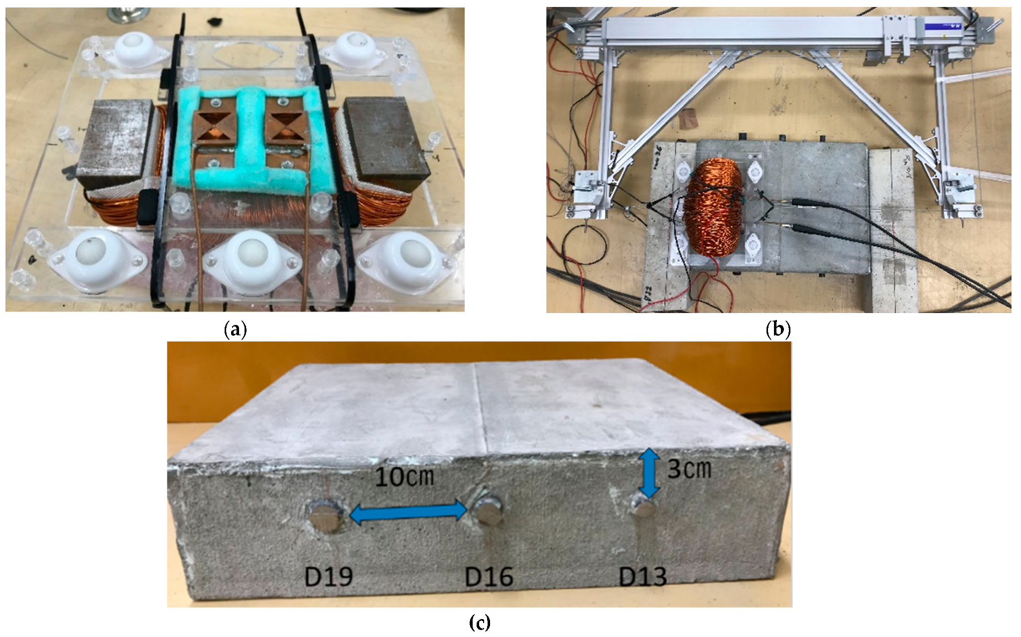
As shown in Figure 5a, the excitation coil consists of a half-toroidal core wound 750 times [37] with enameled wire. The core is made of 100-layer laminated electromagnetic steel plate, the cross sectional area of the poles is 38 × 60 mm, and the width between the poles is 205 mm. A constant alternating current was applied to the coil through a matching capacitor as a series resonance condition. The applied current was 10 A in RMS value, and the applied frequency was 55 Hz, which corresponded to the resonance frequency of the resonator. Cavity backed-bow-tie type slot antennas were used for transmission and reception with a feed point spacing of 40 mm fixed between both poles of the coil. A cushioning material was placed between the antenna and the fixture so that the distance between the antennas and the concrete surface was 1 mm. Five ball bearings were used in the fixture between the coil and antenna to ensure smooth scanning in any direction.
Figure 5b shows an overview of the measurement situation. To improve the reproducibility of the antenna position in scan measurement, a linear actuator connected to a fixture by a non-magnetic metal wire was used. Figure 5c shows an overview of the RC specimen. Three rebars with diameters of 19 mm, 16 mm, and 13 mm are buried in parallel at 100 mm intervals, and the cover of the rebars is 30 mm. The VDR was linearly scanned over the center of the RC specimen perpendicular to the rebar direction. In the scan measurement, 61 points were measured with the measurement interval at 5 mm. The measurement time for a single point is 1 s, resulting in the total measurement time of 2 min.
4.3. Doppler Characteristics in Developed VDR System
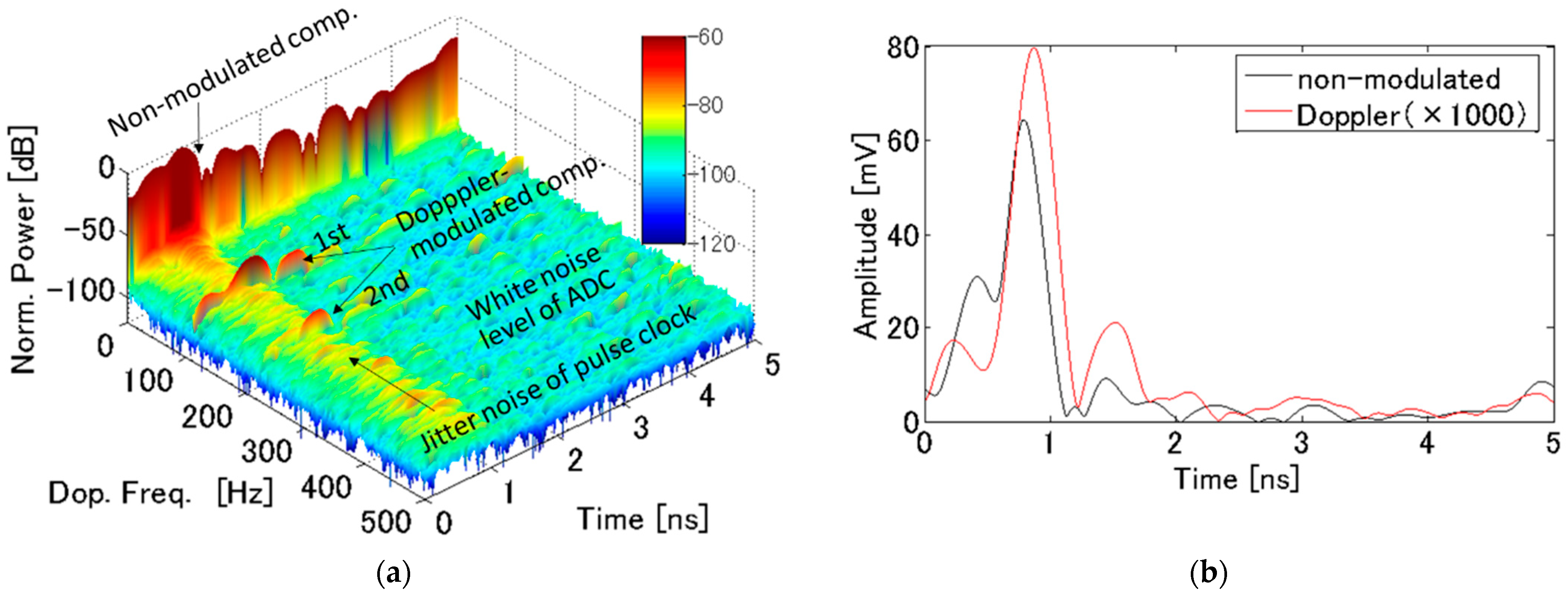
First, consider the 2D radar signal during forced vibration measured at a fixed position for a fixed time. Figure 6a shows an example of the power of the Doppler spectrum measured for 1 s just above the D19 rebar. The vertical axis is expressed in dB scale and normalized by the maximum power. Assuming that the same pulse is repeatedly received, all signals will appear at a Doppler frequency of only zero. So, a strong signal appearing at = 0 is reflection from stationary objects (so-called unmodulated components). However, at = 110 Hz, a 60 dB smaller signal is clearly observed around 1 ns, which corresponds to two attractions in the positive and negative poles of the magnetic field alternating at 55 Hz from the coil. As with the other signal, the noise floor due to thermal noise of the ADC is also observed at −100 dB. In addition, a signal 10 dB greater than the noise floor is observed around 1 ns for a wide Doppler frequency range. This is always −90 dB less than the maximum power of the unmodulated signal, so it is probably due to the jitter noise from the clock generator. The SN ratio for the Doppler component of the D19 rebar buried at 30 mm is estimated to be almost 30 dB. Although increase of a cover of a rebar decreases the signal level, the Doppler components of the developed VDR system appear to have a sufficient SN ratio to perform the following experiments.
Figure 6b shows the envelope of the vibro-radar waveforms of and . The amplitude of the Doppler component is multiplied by 1000. It can be seen that each waveform has a clear peak at 0.9 ns. Assuming that the relative permittivity of concrete is 9, the delay time of the wave reflected from the rebar is about 0.9 ns. In other words, this peak corresponds to the reflection from the rebar. Ground-penetrating radar often has the problem of large direct waves between the transmitter and receiver masking smaller reflected waves. In this measurement, however, the direct wave is smaller than the reflected wave because the antenna can be brought closer to the concrete surface. Therefore, the vibration displacement of the rebar can be estimated from this waveform using Equation (10).
4.4. Imaging Characteritics in Developed VDR System
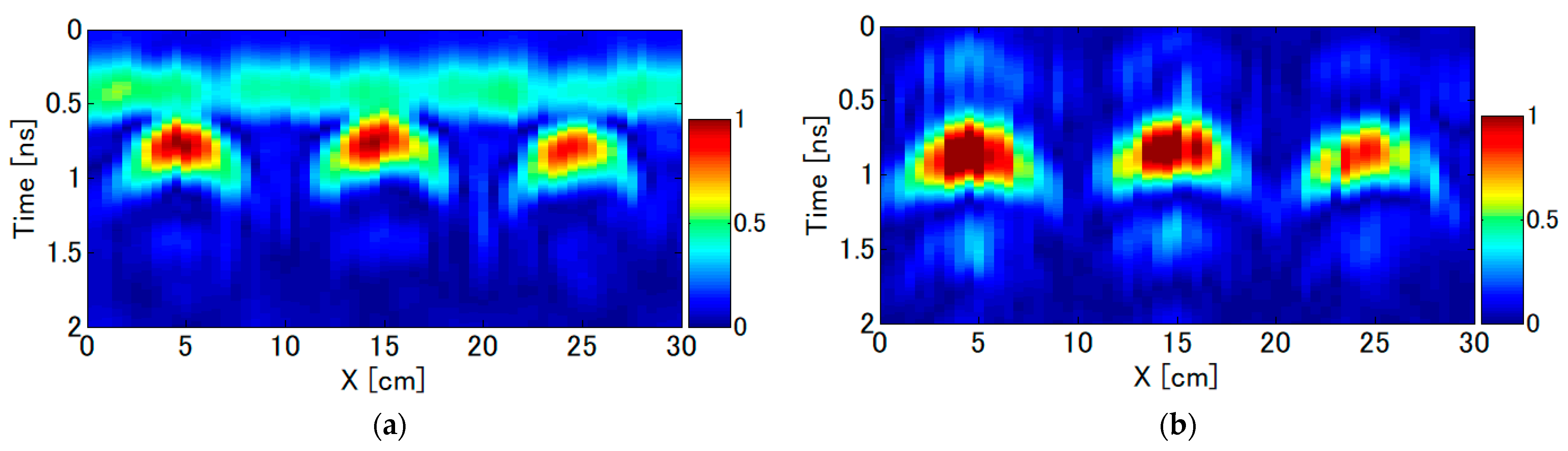
Figure 7a,b show radar profiles of the unmodulated and the Doppler modulated components obtained from the scan measurements in the direction orthogonal to the rebar. The amplitude of each figure is normalized by the maximum amplitude of the figure. The radar profiles for both the unmodulated and Doppler components show parabolic profiles with the vertices around 0.9 ns at intervals of about 10 cm, clearly showing the responses from three isolated rebars. Since the antenna spacing does not change due to forced vibration, the direct wave of about 0.4 ns seen in the unmodulated component is hardly observed in the Doppler component.
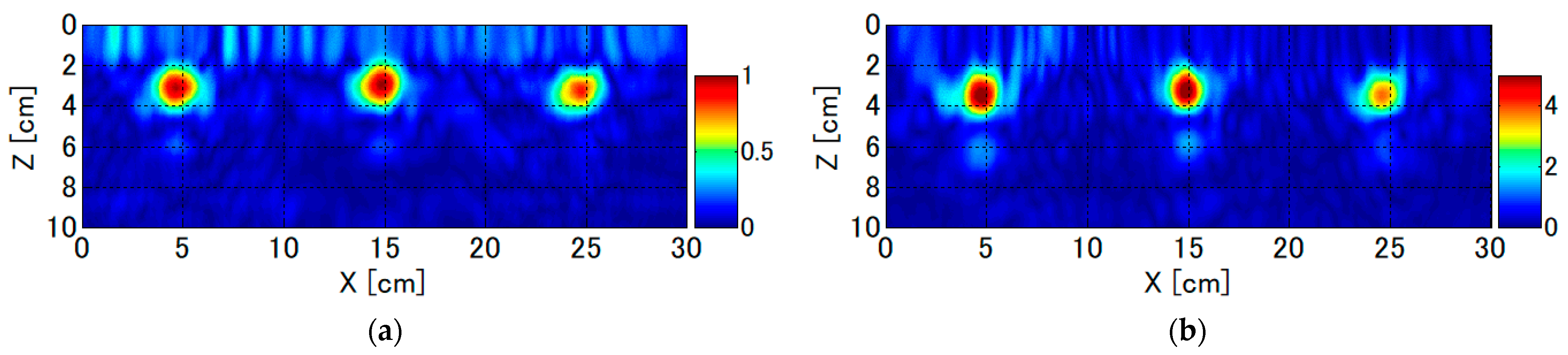
Figure 8a,b show the imaging results in the unmodulated component and the Doppler modulated component calculated from and , respectively. The amplitude of both figures is normalized by the maximum amplitude of the unmodulated component. In the unmodulated component, three isolated peak-like responses are clearly seen at = 4.5, 14.5, and 24.5 cm with a rebar cover of 30 mm, which corresponds to D19, D16, and D13 rebar, respectively. In addition, clear peaks are seen in the Doppler component, indicating that distance information is also preserved in the phase term of the Doppler component. From the peak amplitude ratio of the unmodulated component to the Doppler modulated component, the vibration displacement of the rebar is calculated to be 5.53 μm, 5.38 μm, and 4.41 μm for rebar diameters of 19 mm, 16 mm, and 13 mm, respectively, according to Equation (14).
4.5. Comparison between Developed and Conventional VDR System
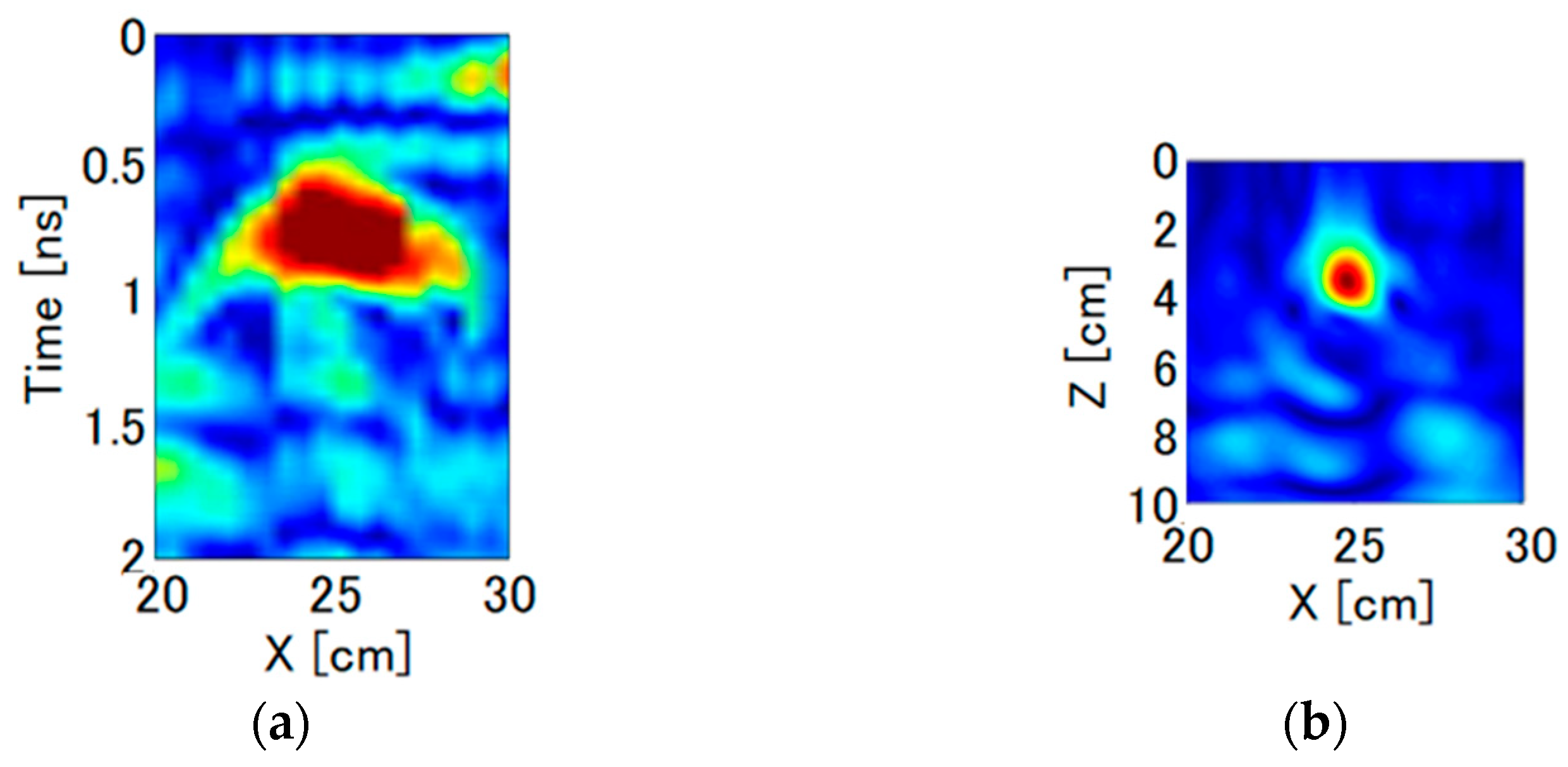
Figure 9 shows the radar profile of the Doppler component measured with a net-work analyzer-based VDR system for the same RC specimen (covering 30 mm, D13 rebar). The measurement time is 120 s for a single point. The radar profile in Figure 9a shows the rebar reflection around 0.9 ns as in Figure 7b, but the signal to noise ratio seemed to be poor, and the imaging result in Figure 9b also shows the noisy image in the area below 60 mm depth. From the imaging result, the developed VDR system achieves a 7 dB better SN ratio than the network analyzer-based system, in spite that the measurement speed of the developed system is 120 times faster.
From the imaging result, we can easily obtain the rebar position. From Equation (11), the vibration displacement is obtained by the peak values of the radar images for the three rebars in each component. In order to confirm the reproducibility of the measurement, the same measurement is repeated four times in the developed VDR system. Figure 10 compares the vibration displacement of the conventional and pulse radar devices for each rebar. The trends of the vibration displacements are similar to each other. The average of the four pulse radar measurements shows that the vibration displacement of the 19 mm rebar is the largest. The 13 mm rebar has a smaller vibration displacement than the other two. It can be seen that the vibration displacement decreases as the rebar diameter decreases for both the conventional and pulse radar methods. This is qualitatively reasonable because the smaller the rebar diameter, the smaller the excitation force. The standard deviation for the 16 mm rebar shows a variation of about 5% for the mean value because of the effect of the step on the concrete surface just above the D16 rebar as shown in Figure 5c. However, the standard deviations for the D19 and D16 rebars are much smaller than the mean. This indicates that the developed VDR system is reliable for measurement of vibrational displacement of rebar.
5. Monitoring Experiment of Spatially Distributed Vibration Displacement of Rebar during Electrolytic Corrosion
5.1. Overview of Electrolytic Corrosion Test
This experiment uses three RC specimens of 100 mm high × 100 mm wide × 300 mm long. Table 1 shows the concrete mix. The compressive strength was 28.2 MPa and the water cement ratio was 63% to facilitate the introduction of chloride ions. Each specimen has one D13, one D16, and one D19 rebar buried at a cover of 30 mm in the center of the specimen. Both ends of the rebar are exposed in the air about 30 mm from the specimen, and no corrosion protection was provided for the rebar ends.
Rebar in concrete is protected from oxidation by being kept in alkaline. However, when concrete is neutralized by chloride ion intrusion, the protective coating of the rebar is destroyed, and corrosion proceeds by the supply of water, oxygen, and electrons. In the electrolytic corrosion test, electrons are forcibly supplied to the rebar of an RC specimen placed in salt water.
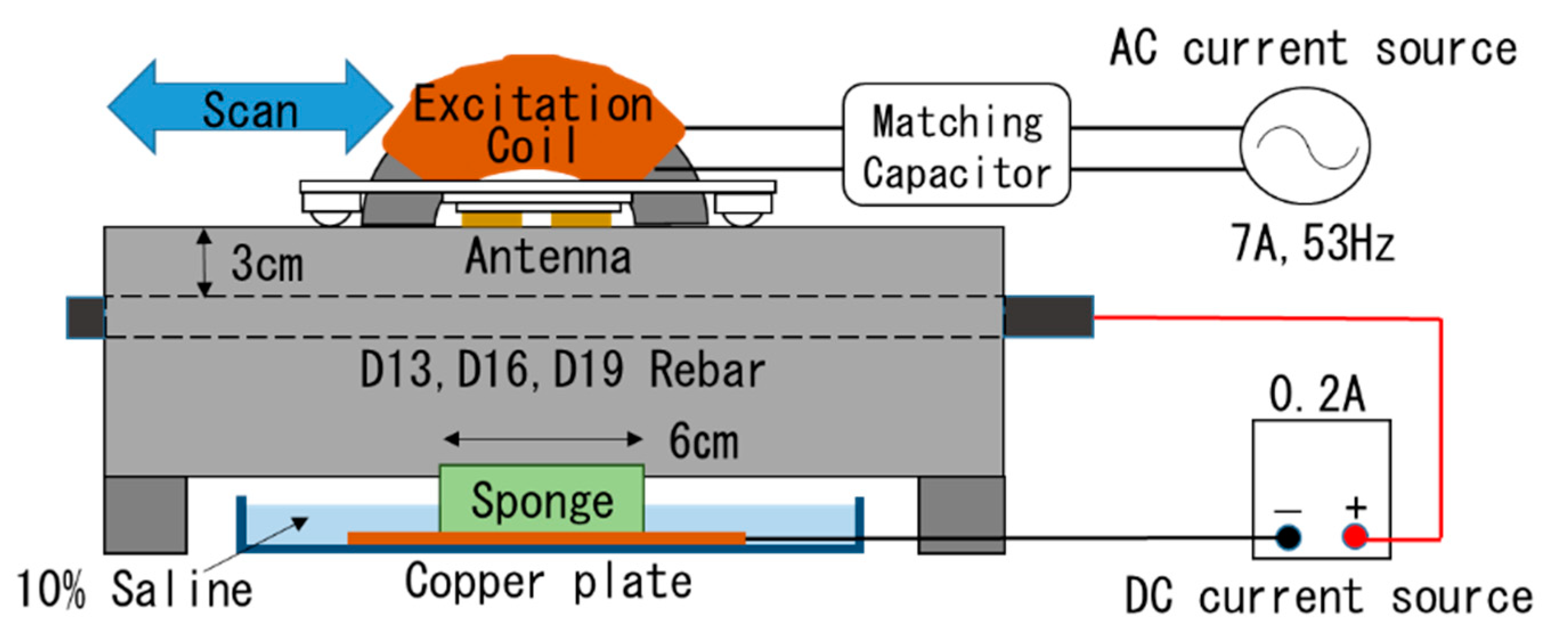
Figure 11 shows an overview of the electrolytic corrosion test. A copper plate soaked in 10% saline solution was connected to the cathode and the rebar to the anode, and a constant DC current of 0.2 A was applied by a constant DC current source. The electrolytic corrosion test was conducted from the bottom surface. To locally introduce saline solution into the concrete, we used a sponge with a width of 60 mm on the center of the bottom of the specimen. At the cumulative current of 6 Ah, cracking and leakage of rust juice were observed on the measurement surface at = 12 cm in the specimen with D13 rebar. On the other hand, in the specimens with D16 and D19 rebar, a small amount of rust juice leaked from the edge of the rebar. After finishing the test, the rebars were detached from the specimens and soaked in a 10% concentration of diammonium hydrogen citrate for 24 h to remove rust. And then a laser displacement meter was scanned in parallel with the rebar using an actuator to evaluate the rib height of the rebars.
5.2. Corrosion Status of Rebars
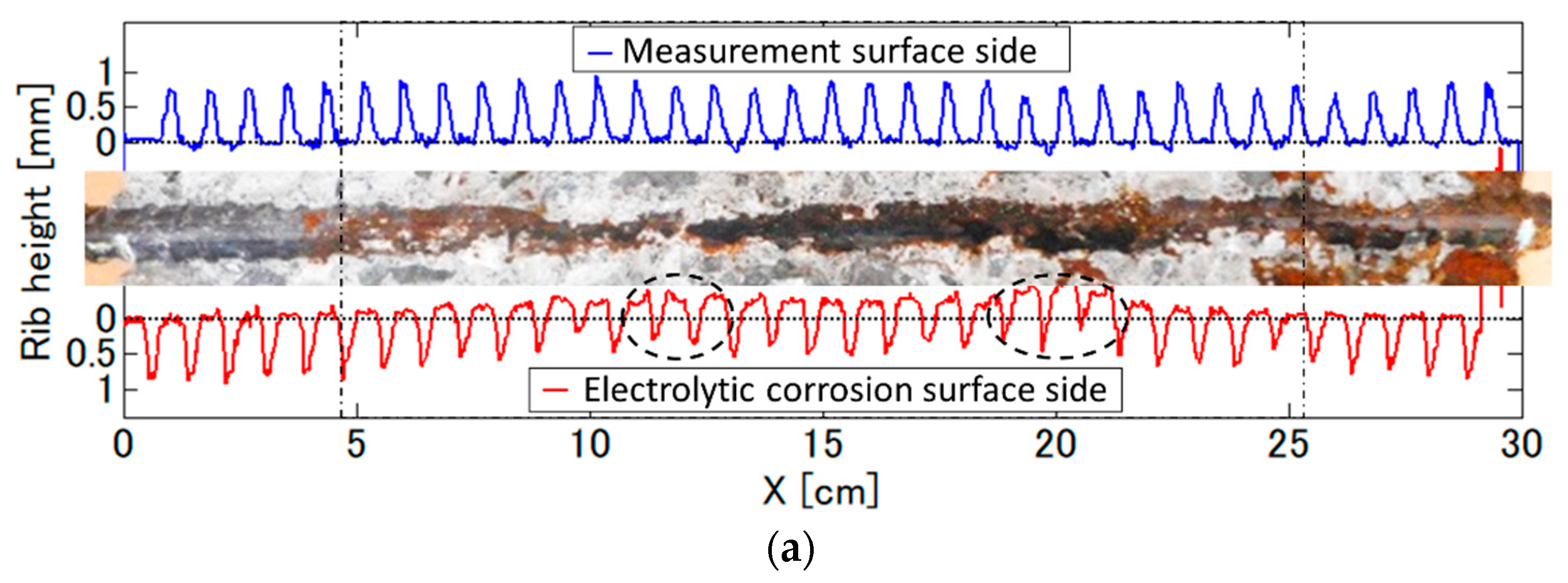
Figure 12 shows the cross-sectional photographs just after the destruction of the concrete. From the photographs, red and black rust are observed. Because oxygen penetrates more easily at the edges of concrete, the red and black rust adhere the to near edge and the interior of the specimen, respectively. The figures also show the rib height in two measurement lines toward the VDR measurement surface (upper side) and the electrolytic corrosion surface (bottom side). The circle with a broken line indicates the area having high corrosion loss. The rib height in the upper side does not change, but that in the lower side decreases from = 6 to 24 cm, which corresponds to the saline injection area. This indicates that the rebar has corroded so severely that its cross section is deformed. In addition, the local decreases in the rib height can be observed at = 12 and 20 cm for the D13 rebar, = 13 and 18 cm for the D16 rebar, and = 14 cm for the D19 rebar. The deformation from 0 to 10 cm in D16 is caused by not corrosion but a role mark on the rebar.
5.3. Monitoring Results for Spatial Distribution of Rebar Vibration Displacement
As the electrolytic corrosion test was conducted from the bottom surface, VDR scan measurements were performed from the top surface during the test. In VDR measurements, a constant alternating current induced on the excitation coil was 7 A in RMS value and had a frequency of 53 Hz. The 2D radar profiles for unmodulated and Doppler modulated components were obtained by scan measurements at 61 points with 5 mm intervals along a line not perpendicular but parallel to the rebar direction. It took 120 s to scan for one measurement line. The scan measurements were repeated 21 times at a cumulative current interval of 0.5 Ah up to 10 Ah.
Figure 13 shows examples of imaging results of the unmodulated and Doppler modulated components obtained from the VDR scan measurement for the RC specimen with the D13 rebar in a healthy condition. Assuming the relative permittivity of the concrete to be 11, it can be seen that the reflection response of the rebar parallel to the scan direction is observed for both components at almost all scan locations at a depth of 30 mm, indicating that generally good imaging results are obtained. Since the position dependence of the rebar reflection amplitude differs between the unmodulated and Doppler modulated components, it is expected that the vibrational displacement of the rebar is localized.
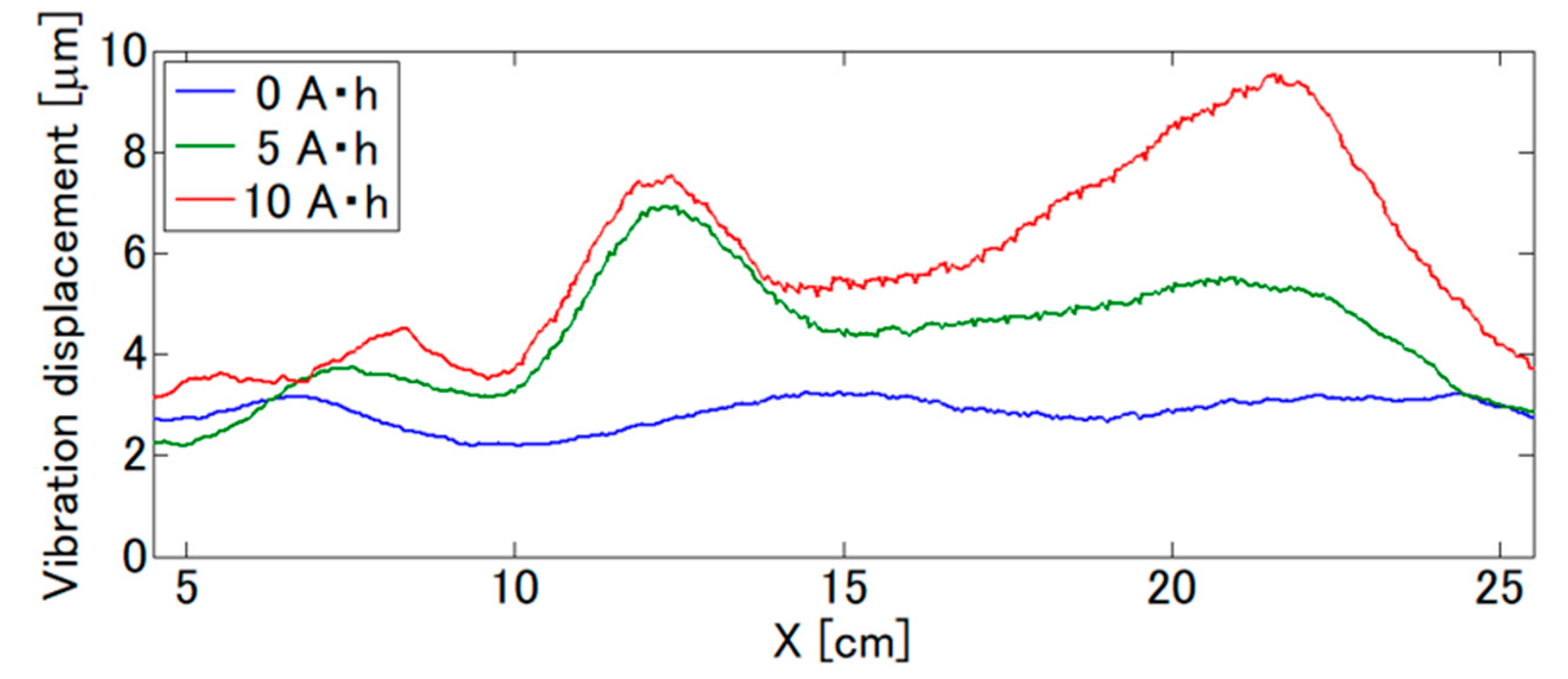
The vibration displacement spatially distributed over the whole rebar was evaluated. Figure 14 shows the results of the vibration displacement of the rebar from the VDR images. The results are also shown at cumulative currents of 5 Ah and 10 Ah. The vibration displacement at a cumulative current of 0 Ah is approximately 3 µm, and the variation in the scan direction is small, indicating that the scan measurement is highly reproducible. At a cumulative current of 5 Ah, the vibration displacement around = 12 cm increased by a factor of 3 to 9 µm, corresponding to the rust juice leakage observed at = 12 cm on the top surface of the specimen due to the surface crack extension from a cumulative current of 6 Ah. At a cumulative current of 10 Ah, the overall vibration displacement increased, with the maximum vibration displacement occurring near = 22 cm. Thus, a clear change in spatial distribution was also observed.
Figure 15 shows the dependence of the spatial distribution of the rebar vibration displacement on the cumulative current for each specimen. At = 12 cm for the D13 rebar specimen, the vibration displacement began to increase locally 3 Ah before the rust juice leaked out. On the other hand, around = 22 cm, the vibration displacement gradually began to increase and finally reached 10 µm, corresponding to the increase in the cumulative current. In the D16 rebar specimen, it can be seen that the vibration displacement rises and falls sharply at the cumulative currents of 3 Ah, 4 Ah, and 6.5 Ah, but this is due to a measurement error. The average vibration displacement was almost 5 µm, but locally, the vibration displacement increased at around = 13 cm and 18 cm, starting at about a cumulative current of 4 Ah. In the D19 rebar specimen, after 7 Ah of cumulative current, the overall vibration displacement gradually increased in the center of the specimen and reached about twice the vibration displacement in the healthy condition. Although the vibration displacement eventually increased to 7 µm, the increase rate of the vibration displacement with respect to the increase in cumulative current is the lowest compared to the other specimens.
6. Discussion
The saline solution was introduced from 12 to 18 cm, and the vibration displacement generally increased near this region, but not to a maximum at the central area = 15 cm. This may be due to the fact that oxygen is necessary for rebar corrosion in addition to chloride ions and water. Therefore, it is considered that the displacement increased outside of the central area where the oxygen penetration and the chloride ion concentration are high.
Moreover, a local increase in vibration displacement was observed in all specimens, and their locations coincided well with those of the rebar with localized corrosion loss. This indicates that the increase in local vibration displacement in the VDR system may be able to evaluate localized corrosion of the rebar. Its spatial resolution depends on the spatial resolution of the radar image, and Figure 8 also shows that it is about 1 cm. The spatial resolution of the surface potential measurement [9], which is practically used in existing corrosion evaluation methods, is several tens of centimeters or more, and the proposed VDR system is considered possible to evaluate local rebar corrosion with a high spatial resolution.
In addition, it has been clarified that there is a certain degree of correlation between the vibration displacement and the amount of corrosion. However, quantitative discussion is difficult because the mechanisms of the increase in vibration displacement due to corrosion are not clarified. Here, related to the mechanisms, this experiment revealed that the width where the vibration displacement locally increased was on the order of a few centimeters. From Figure 12, the maximum loss in the rib height under this corrosion condition is about 0.5 mm, which corresponds to a 2.6 to 3.8% reduction of the rebar diameter. So, the local increase in rebar vibration displacement obtained in the VDR method may reflect the local change in not mechanical but electromagnetic properties of a rebar due to corrosion.
In Figure 12, a large amount of black rust deposition due to electrolytic corrosion was observed in the center of the rebar. The magnitude of the Doppler component is determined by the product of the amplitude of the unmodulated component (reflection coefficient) and the magnitude of the vibration displacement. In general, black rust in rust juice is considered to be more sensitive to the magnetic field than solid rebar. Since a VDR image does not clearly resolve rebar and black rust, both are measured as a single reflected wave. Thus, the Doppler component of the rebar with localized black rust may increase locally. The exact distribution of black rust around the rebar is not known in this measurement, and further investigation of the relationship between black rust distribution and locally increased vibration displacement of the rebar may allow for a more quantitative evaluation of rebar corrosion.
7. Conclusions
In this paper, a vibro-Doppler radar (VDR) system using an impulse radar has been developed to overcome the time-consuming problem of conventional VDR systems using network analyzers. The developed VDR achieved a dynamic range of 90 dB with a measurement time of 1 s, which is 120 times faster than conventional systems. We also proposed a method for estimating vibration displacement by image processing: VDR images have a spatial resolution of 1 cm, which provides vibration displacement of a spatially distributed target. The VDR system was scanned parallel to the rebar, and the distribution of vibration displacement of the rebar was successfully evaluated.
Through an electrolytic corrosion test, changes in the vibration displacement distribution due to corrosion were monitored simultaneously. After the electrolytic corrosion test, the rib heights obtained from the laser displacement meter were investigated, and the results showed that the rebar tended to decrease in height by a maximum of 0.5 mm under the corrosion conditions, but the location of the strongest decrease appeared to be localized off center, although the nodal height in the middle of the rebar tended to decrease.
The distribution of vibration displacement during the electrolytic corrosion test showed that vibration displacement tended to increase with corrosion for all specimens, and the vibration displacement was locally increased several times. The width where the vibration displacement locally increases was found to be as narrow as a few centimeters. The localized position of vibration displacement and the localized position of rebar corrosion loss were generally in agreement with each other.
Therefore, it is demonstrated that the proposed VDR system can detect corrosion localized in a width of several centimeters on a rebar by the spatial distribution of the vibration displacement. Because of the localization of corrosion, VDR measurement should be performed while scanning, rather than being fixed.
In the future, we plan to develop a system that can evaluate the spatial distribution of deterioration of large specimens, which has been difficult in the past, from vibration displacement imaging by scanning type measurement, which has many measurement points, by taking advantage of the merits of shorter measurement time and higher accuracy.
Author Contributions
Conceptualization, T.M.; methodology, T.M.; software, T.M. and Y.N.; validation, T.M. and Y.N.; measurement, Y.N. All authors have read and agreed to the published version of the manuscript.
Funding
This work was supported by JSPS KAKENHI Grant Number JP20H02395 and 2021 General Research Grants in SECOM Science and Technology Foundation.
Data Availability Statement
The data presented in this study are available on request from the corresponding author.
Acknowledgments
I would like to thank Mitsuo Ozawa in Gunma University for providing reinforced concrete products.
Conflicts of Interest
The authors declare no conflict of interest.
References
- Grantham, M. Diagnosis, inspection, testing and repair of reinforced concrete structures. Adv. Concr. Technol. 2003, 2, 1–54. [Google Scholar] [CrossRef]
- Popovics, J.S.; Rose, J.L. A survey of developments in ultrasonic NDE of concrete. IEEE Trans. Ultrason. Ferroelectr. Freq. Control 1994, 41, 140–143. [Google Scholar] [CrossRef]
- Ndagi, A.; Umar, A.A.; Hejazi, F.; Jaafar, M.S. Non-destructive assessment of concrete deterioration by ultrasonic pulse velocity: A review. IOP Conf. Ser. Earth Environ. Sci. 2019, 357, 012015. [Google Scholar] [CrossRef]
- Shaaban, I.G.; Rizzuto, J.P.; El-Nemr, A.; Bohan, L.; Ahmed, H.; Tindyebwa, H. Mechanical properties and air permeability of concrete containing waste tyres extracts. J. Mater. Civ. Eng. 2001, 3, 04020472. [Google Scholar]
- Brencea, J.R.; Brown, D.E. Data mining corrosion from eddy current non-destructive tests. Comput. Ind. Eng. 2002, 43, 821–840. [Google Scholar] [CrossRef]
- Novikov, V.F.; Sokolov, R.A.; Neradovskiy, D.F.; Muratov, K.R. A technique for predicting steel corrosion resistance. IOP Conf. Ser. Mater. Sci. Eng. 2018, 289, 012013. [Google Scholar] [CrossRef]
- Frankowski, P.K.; Chady, T.; Zieliński, A. Magnetic force induced vibration evaluation (M5) method for frequency analysis of rebar-debonding in reinforced concrete. Measurement 2021, 182, 109655. [Google Scholar] [CrossRef]
- ASTM C876-15; Standard Test Method for Corrosion Potentials of Uncoated Reinforcing Steel in Concrete. ASTM International: West Conshohocken, PA, USA, 2015. Available online: https://www.astm.org/Standards/C876.htm (accessed on 2 August 2022).
- Elsener, B.; Andrade, C.; Gulikers, J.; Polder, R.; Raupach, M. Half-cell potential measurements—Potential mapping on rein-forced concrete structures. Mater. Struct. 2003, 36, 461–471. [Google Scholar] [CrossRef]
- Sadowski, L. Methodology for assessing the probability of corrosion in concrete structures on the basis of half-cell potential and concrete resistivity measurements. Sci. World J. 2013, 2013, 714501. [Google Scholar] [CrossRef]
- Medeiros, M.H.F.; Rocha, F.C.; Medeiros, R.A., Jr.; Helene, P. Corrosion potential: Influence of moisture, water-cement ratio, chloride content and concrete cover. Rev. IBRACON Estrut. Mater. 2017, 10, 864–885. [Google Scholar] [CrossRef]
- Stern, M.; Geary, A.L. Electrochemical polarization I. A theoretical analysis of shape of polarization curves. J. Electrochem. Soc. 1957, 104, 56–63. [Google Scholar] [CrossRef]
- Song, H.W.; Saraswathy, V. Corrosion monitoring of reinforced concrete structures—A review. Int. J. Electrochem. Sci. 2007, 2, 1–28. [Google Scholar]
- Figueira, R.B. Electrochemical sensors for monitoring the corrosion conditions of reinforced concrete structures: A review. Appl. Sci. 2017, 7, 1157. [Google Scholar] [CrossRef]
- MacDonald, D.D.; El-Tantawy, Y.A.; Rocha-Filho, R.C.; Urquidi-Macdonald, M. Evaluation of electrochemical impedance techniques for detecting corrosion on rebar in reinforced concrete. In Research Report on Strategic Highway Research Program; 1994; Available online: http://onlinepubs.trb.org/onlinepubs/shrp/SHRP-91-524.pdf (accessed on 20 August 2022).
- Ribeiro, D.; Abrantes, J. Application of electrochemical impedance spectroscopy (EIS) to monitor the corrosion of reinforced concrete: A new approach. Constr. Build. Mater. 2016, 111, 98–104. [Google Scholar] [CrossRef]
- Sohail, M.G.; Kahraman, R.; Alnuaimi, N.A.; Gencturk, B.; Alnahhal, W.; Dawood, M.; Belarbi, A. Electrochemical behavior of mild and corrosion resistant concrete reinforcing steels. Constr. Build. Mater. 2020, 232, 117205. [Google Scholar] [CrossRef]
- Sansalone, M.; Streett, W.B. Impact-Echo: Nondestructive Testing of Concrete and Masonry; Bullbrier Press: Jersey Shore, PA, USA, 1997. [Google Scholar]
- Ahmad, N.; Rahim, R.A.; Rahim, H.A.; Rahiman, M. A review of ultrasonic application on non-destructive testing method for concrete structure. J. Teknol. 2014, 70, 112–119. [Google Scholar] [CrossRef]
- Frankowski, P.K.; Chady, T. Impact of magnetization on the evaluation of reinforced concrete structures using DC magnetic methods. Materials 2022, 15, 857. [Google Scholar] [CrossRef]
- Shull, P.J. Nondestructive Evaluation: Theory, Techniques and Applications; CRC Press: New York, NY, USA, 2002. [Google Scholar]
- Rubinacci, G.; Tamburrino, A.; Ventre, S. Concrete rebars inspection by eddy current testing. Int. J. Appl. Electromagn. Mech. 2007, 25, 333–339. [Google Scholar] [CrossRef]
- De Alcantara, J.N.P.; Da Silva, F.M.; Guimarães, M.T.; Pereira, M.D. Corrosion assessment of steel bars used in reinforced concrete structures by means of eddy current testing. Sensors 2015, 16, 15. [Google Scholar] [CrossRef]
- Kobayashi, K.; Banthia, N. Corrosion detection in reinforced concrete using induction heating and infrared thermography. J. Civ. Struct. Health Monit. 2011, 1, 25–35. [Google Scholar] [CrossRef]
- Baek, S.; Xue, W.; Feng, M.Q.; Kwon, S. Nondestructive corrosion detection in RC through integrated heat induction and IR thermography. J. Nondestruct. Eval. 2012, 31, 181–190. [Google Scholar] [CrossRef]
- Sirca, G.F.; Adeli, H. Infrared thermography for detecting defects in concrete structures. J. Civ. Eng. Manag. 2018, 24, 508–515. [Google Scholar] [CrossRef]
- Annan, A.P. Electromagnetic Principles of Ground Penetrating Radar. In Ground Penetrating Radar: Theory and Applications; Elsevier: Amsterdam, The Netherlands, 2009; pp. 3–40. [Google Scholar]
- Hasan, I.; Yazdani, N. An experimental study for quantitative estimation of rebar corrosion in concrete using ground penetrating radar. J. Eng. 2016, 2016, 8536850. [Google Scholar] [CrossRef]
- Zaki, A.; Johari, M.A.M.; Hussin, W.M.A.W.; Jusman, Y. Experimental assessment of rebar corrosion in concrete slab using ground penetrating radar (GPR). Int. J. Corros. 2018, 2018, 5389829. [Google Scholar] [CrossRef]
- Tešić, K.; Baričević, A.; Serdar, M. Non-destructive corrosion inspection of reinforced concrete using ground-penetrating radar: A review. Materials 2021, 14, 975. [Google Scholar] [CrossRef]
- Hugenschmidt, J.; Loser, R. Detection of chlorides and moisture in concrete structures with ground penetrating radar. Mater. Struct. 2007, 41, 785–792. [Google Scholar] [CrossRef]
- Senin, S.; Hamid, R. Ground penetrating radar wave attenuation models for estimation of moisture and chloride content in concrete slab. Constr. Build. Mater. 2016, 106, 659–669. [Google Scholar] [CrossRef]
- Wakayama, T.; Sato, T.; Kimura, I. Radar image-reconstruction in layered inhomogeneous media by discrete model-fitting method. IEEE Antennas Propag. Soc. Int. Symp. 1994, I–III, 1664–1667. [Google Scholar] [CrossRef]
- Tanaka, S.; Yamada, M. Non-destructive inspection of concrete structures using an electromagnetic wave (radar) based on a signal propagation model. Trans. Soc. Instrum. Control Eng. 2003, 39, 432–440. [Google Scholar] [CrossRef]
- Shen, R.; Zhao, Y.; Hu, S.; Li, B.; Bi, W. Reverse-time migration imaging of ground-penetrating radar in NDT of reinforced concrete structures. Remote Sens. 2021, 13, 2020. [Google Scholar] [CrossRef]
- Takayama, J.; Ohara, Y.; Sun, W. Nondestructive evaluation of air voids in concrete structures using microwave radar technique. SICE J. Control Meas. Syst. Integr. 2021, 15, 26–47. [Google Scholar] [CrossRef]
- Miwa, T. Non-destructive and quantitative evaluation of rebar corrosion by a vibro-Doppler radar method. Sensors 2021, 21, 2546. [Google Scholar] [CrossRef] [PubMed]
- Munakata, K.; Kamada, T.; Uchida, S.; Mae, H.; Minezawa, H. Nondestructive evaluation of deterioration around rebar based on elastic waves generated by electromagnetic force. In Proceedings of the 7th International Symposium on Nondestructive Testing in Civil Engineering, Nantes, France, 30 June–3 July 2009; Available online: https://www.ndt.net/article/ndtce2009/papers/183.pdf (accessed on 3 September 2022).
- Li, C.; Lubecke, V.M.; Boric-Lubecke, O.; Lin, J. A review on recent advances in Doppler radar sensors for noncontact healthcare monitoring. IEEE Trans. Microw. Theory Tech. 2013, 61, 2046–2060. [Google Scholar] [CrossRef]
- Van, N.T.P.; Tang, L.; Demir, V.; Hasan, S.F.; Minh, N.D.; Mukhopadhyay, S. Review-microwave radar sensing systems for search and rescue purposes. Sensors 2019, 19, 2879. [Google Scholar] [CrossRef]
- Charvat, G.L.; Kempel, L.C.; Rothwell, E.J.; Coleman, C.; Mokole, E.L. A through-dielectric radar imaging system. IEEE Trans. Antennas Propag. 2010, 58, 2594–2603. [Google Scholar] [CrossRef]
Figure 1.
Geometry of problem.

Figure 2.
Flow of vibration displacement measurement obtained with developed VDR.

Figure 3.
Developed impulse radar system: (a) Block diagram; (b) Inside of radar equipment.

Figure 4.
Characteristics of the developed radar system when transmitting and receiving antennas are connected with a 40 dB attenuator: (a) Impulse response; (b) Power spectrum.
Figure 4.
Characteristics of the developed radar system when transmitting and receiving antennas are connected with a 40 dB attenuator: (a) Impulse response; (b) Power spectrum.

Figure 5.
Experimental condition: (a) Arrangement of excitation coil, antenna, and fixture; (b) Measurement situation; (c) Overview of RC specimen.
Figure 5.
Experimental condition: (a) Arrangement of excitation coil, antenna, and fixture; (b) Measurement situation; (c) Overview of RC specimen.

Figure 6.
Result of VDR measurement for 1 s just above D19 rebar at 55 Hz vibration frequency: (a) Power of Doppler spectrum vs. delay time of radar waveform in VDR signal; (b) Envelope waveform for non-modulated and Doppler modulated signal.
Figure 6.
Result of VDR measurement for 1 s just above D19 rebar at 55 Hz vibration frequency: (a) Power of Doppler spectrum vs. delay time of radar waveform in VDR signal; (b) Envelope waveform for non-modulated and Doppler modulated signal.

Figure 7.
Radar profile measured by the developed VDR for a RC specimen buried rebars at = 5, 15 and 25 cm with 30 mm cover: (a) Unmodulated component ; (b) Doppler modulated component .
Figure 7.
Radar profile measured by the developed VDR for a RC specimen buried rebars at = 5, 15 and 25 cm with 30 mm cover: (a) Unmodulated component ; (b) Doppler modulated component .

Figure 8.
Imaging results obtained by developed VDR for RC specimen buried rebars at = 5, 15 and 25 cm with 30 mm cover: (a) Unmodulated component ; (b) Doppler modulated component .
Figure 8.
Imaging results obtained by developed VDR for RC specimen buried rebars at = 5, 15 and 25 cm with 30 mm cover: (a) Unmodulated component ; (b) Doppler modulated component .

Figure 9.
Scan measurement results of the Doppler modulated component by a conventional VDR system based on a network analyzer for the same RC specimen (cover 30 mm, D13 rebar): (a) Radar profile; (b) Imaging result.
Figure 9.
Scan measurement results of the Doppler modulated component by a conventional VDR system based on a network analyzer for the same RC specimen (cover 30 mm, D13 rebar): (a) Radar profile; (b) Imaging result.

Figure 10.
Comparison of the measured vibration displacement of the rebar between the developed and conventional VDR systems.
Figure 10.
Comparison of the measured vibration displacement of the rebar between the developed and conventional VDR systems.

Figure 11.
Overview of electrolytic corrosion test.

Figure 12.
Cross-sectional photographs of the split specimens after destruction and rib height of extracted rebars for (a) D13, (b) D16, and (c) D19, obtained with a laser displacement meter. The scan results toward the side of the top surface and the bottom surface are shown in blue and red lines, respectively. The circle with a broken line indicates the area having high corrosion loss.


Figure 13.
Imaging results obtained in measurement scanned by VDR for specimen with a healthy D13 rebar: (a) Unmodulated radar component; (b) Doppler modulated component (Cumulative current 0 A-h).
Figure 13.
Imaging results obtained in measurement scanned by VDR for specimen with a healthy D13 rebar: (a) Unmodulated radar component; (b) Doppler modulated component (Cumulative current 0 A-h).

Figure 14.
Measured spatial distribution of vibration displacement for D13 rebar in concrete while electrolytic corrosion testing.
Figure 14.
Measured spatial distribution of vibration displacement for D13 rebar in concrete while electrolytic corrosion testing.

Figure 15.
Dependence of spatial distribution of vibrational displacement obtained by VDR for: (a) D13 rebar; (b) D16 rebar; and (c) D19 rebar on cumulative current during electrolytic corrosion testing. The color bar corresponds to the vibration displacement.
Figure 15.
Dependence of spatial distribution of vibrational displacement obtained by VDR for: (a) D13 rebar; (b) D16 rebar; and (c) D19 rebar on cumulative current during electrolytic corrosion testing. The color bar corresponds to the vibration displacement.


Table 1.
Mix and mechanical properties of concrete used for electrolytic corrosion tests.
| W/C [%] | [kg/m3] | Air [%] | Compressiv Strength [MPa] | Tensile Strength [MPa] | Modulus of Elasticity [GPa] | ||||
|---|---|---|---|---|---|---|---|---|---|
| Water W | Cement C | Fine Aggregate S | Course Aggregate G | Admixture Ad | |||||
| 63 | 180 | 285 | 752 | 1155 | 2.85 | 4.5 | 28.2 | 4.45 | 31.2 |
Publisher’s Note: MDPI stays neutral with regard to jurisdictional claims in published maps and institutional affiliations. |
© 2022 by the authors. Licensee MDPI, Basel, Switzerland. This article is an open access article distributed under the terms and conditions of the Creative Commons Attribution (CC BY) license (https://creativecommons.org/licenses/by/4.0/).
Share and Cite
MDPI and ACS Style
Miwa, T.; Nakazawa, Y. Nondestructive Evaluation of Localized Rebar Corrosion in Concrete Using Vibro-Radar Based on Pulse Doppler Imaging. Remote Sens. 2022, 14, 4645. https://0-doi-org.brum.beds.ac.uk/10.3390/rs14184645
AMA Style
Miwa T, Nakazawa Y. Nondestructive Evaluation of Localized Rebar Corrosion in Concrete Using Vibro-Radar Based on Pulse Doppler Imaging. Remote Sensing. 2022; 14(18):4645. https://0-doi-org.brum.beds.ac.uk/10.3390/rs14184645
Chicago/Turabian StyleMiwa, Takashi, and Yuri Nakazawa. 2022. "Nondestructive Evaluation of Localized Rebar Corrosion in Concrete Using Vibro-Radar Based on Pulse Doppler Imaging" Remote Sensing 14, no. 18: 4645. https://0-doi-org.brum.beds.ac.uk/10.3390/rs14184645
Note that from the first issue of 2016, this journal uses article numbers instead of page numbers. See further details here.