
Giant Magnetoresistance Sensors: A Review on Structures and Non-Destructive Eddy Current Testing Applications


Abstract
:1. Introduction
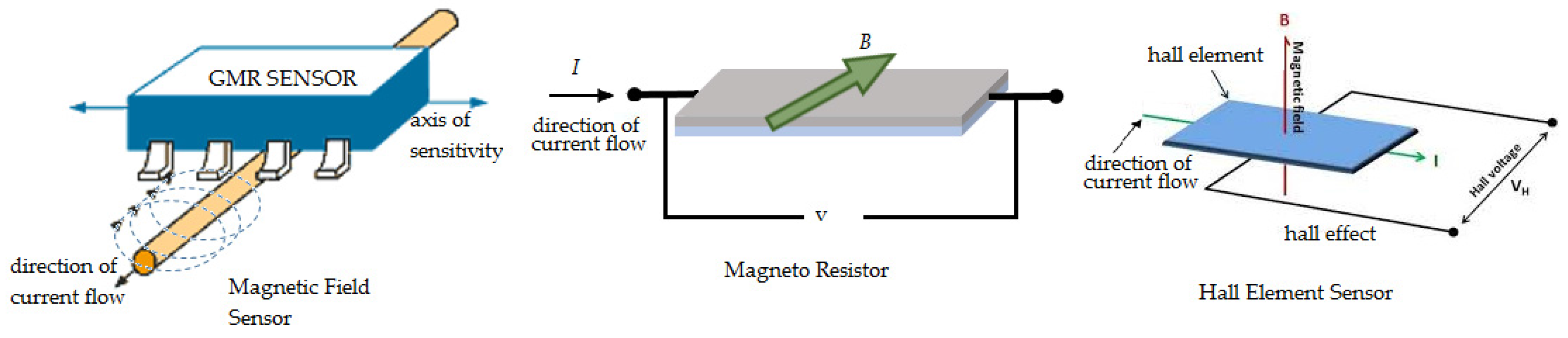
2. Overview of Giant Magnetoresistance Sensors
2.1. Giant Magnetoresistance Spin Valve Sensor
2.2. Giant Magnetoresistance Multilayer Sensor
3. Types of Non-Destructive Eddy Current Testing Probe
3.1. Bobbin Probe
3.2. Full Saturation Probe
3.3. Rotating Bobbin Probe
3.4. Array Probe
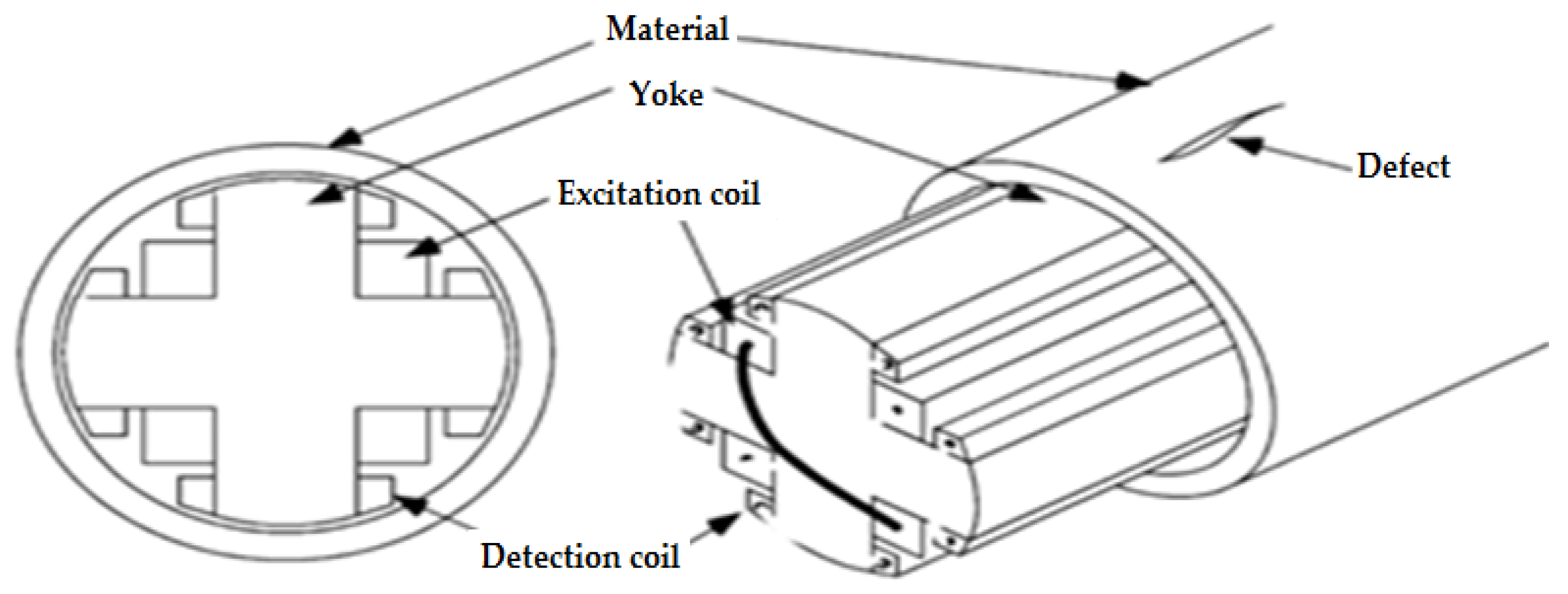
3.5. C-Probe
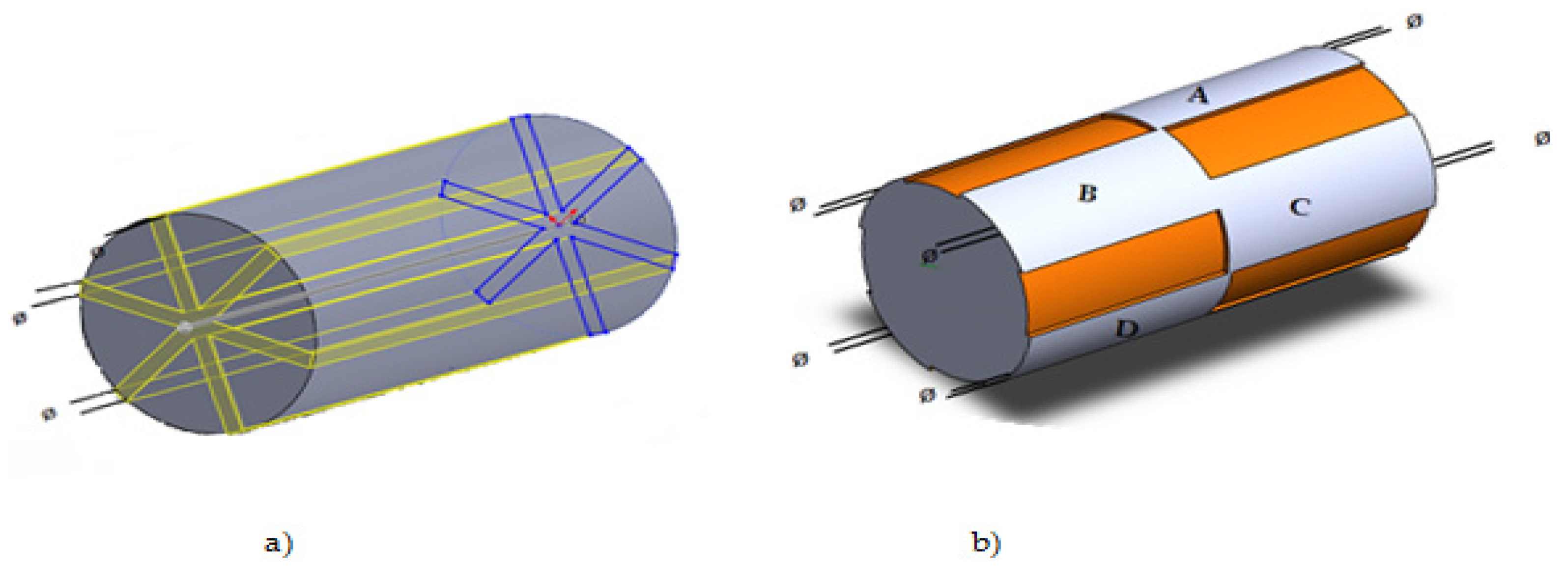
3.6. X-Probe
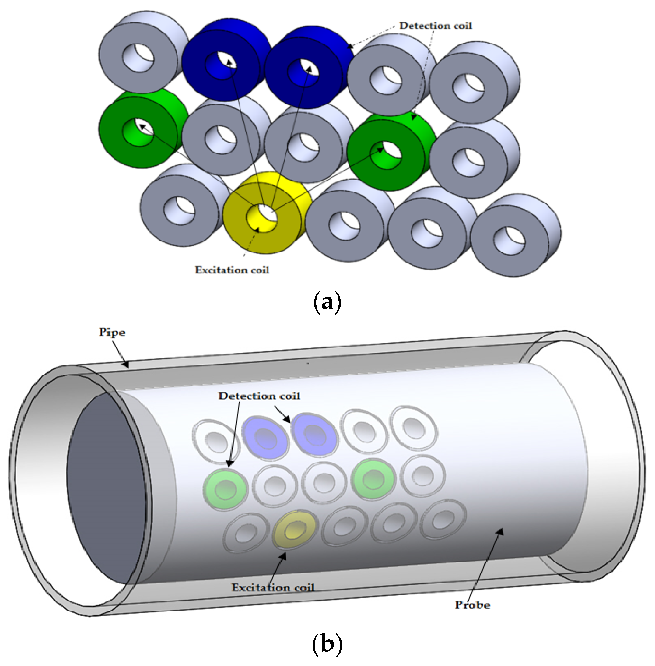
3.7. Smart Array Probe
- One transmitter and four receivers
- Every coil works in either excitation or detection mode
- Simple DAQ circuits
- Circumferential mode with higher resolutions
- No need for axial position correction
- Less time slots
3.8. Intelligent Probe
3.9. Rotational Magnetic Flux Sensor
3.10. Rotating Magnetic Field Probe
4. The Influence of Various Parameters on the GMR Measurement
4.1. Structural Quality of Giant Magnetoresistance Sensor
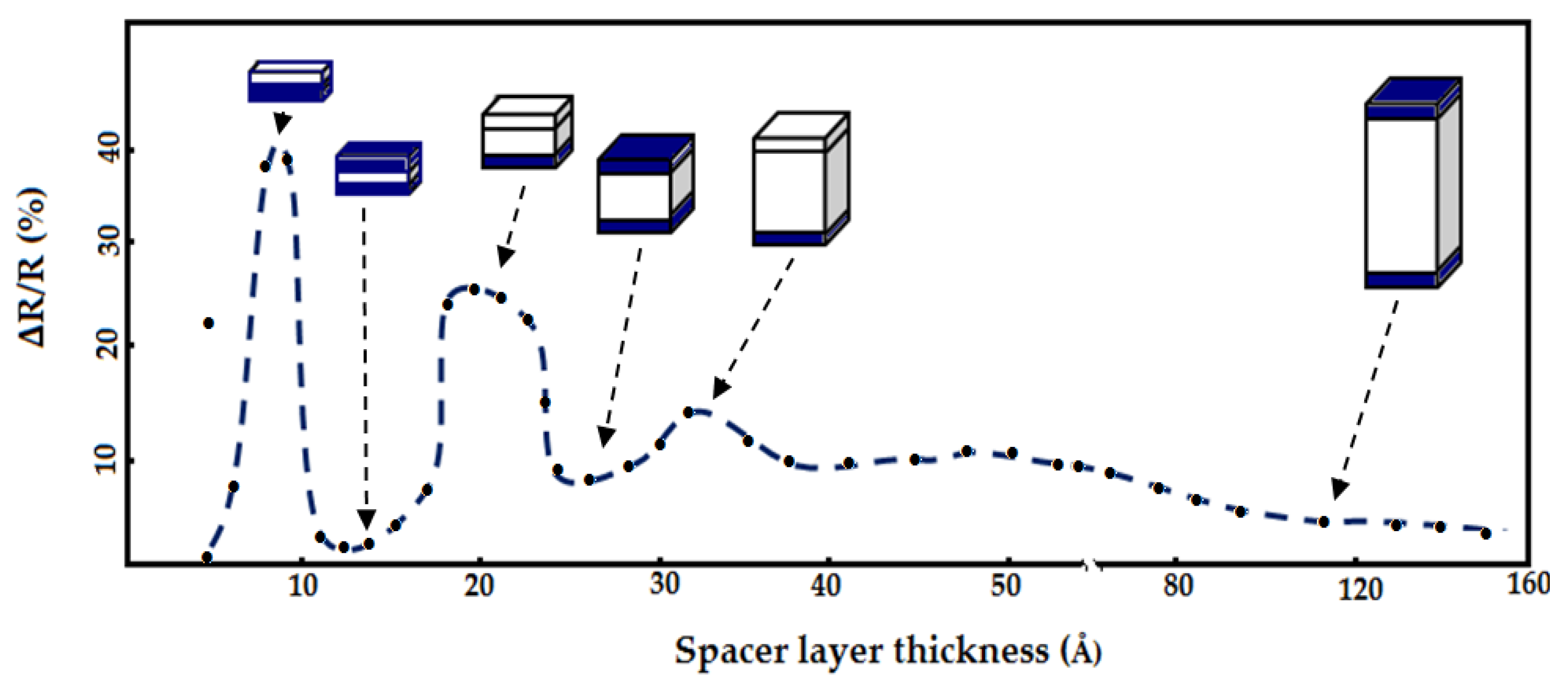
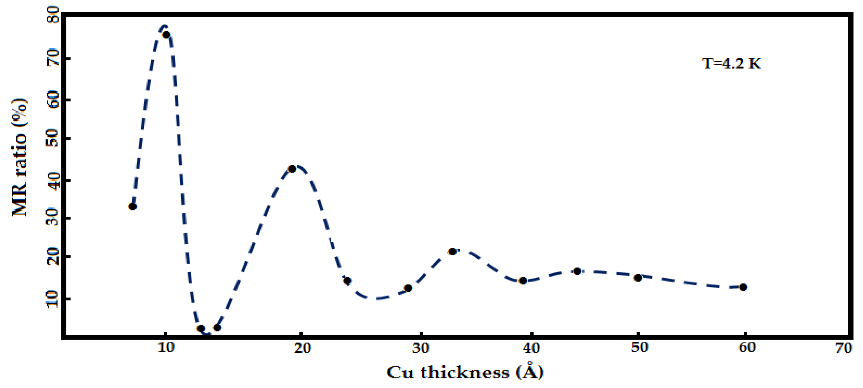
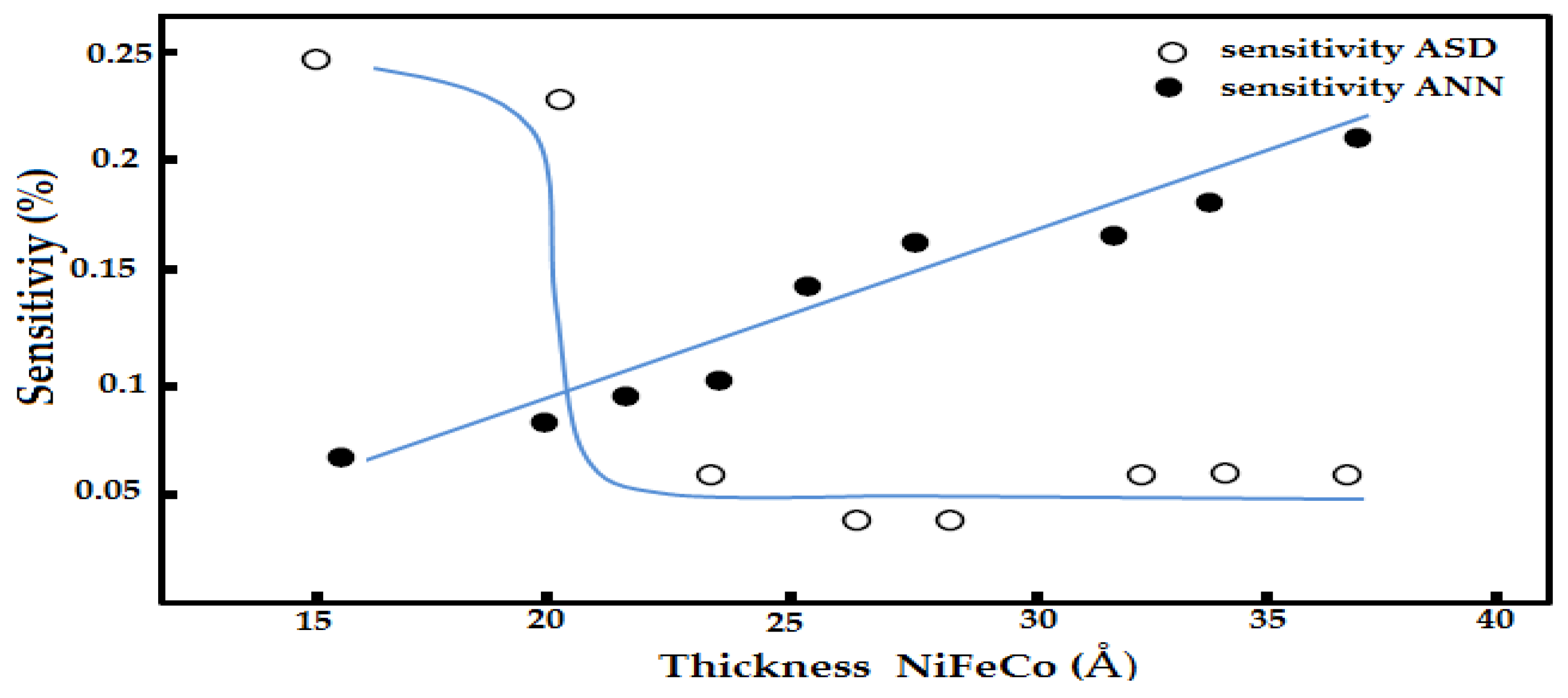
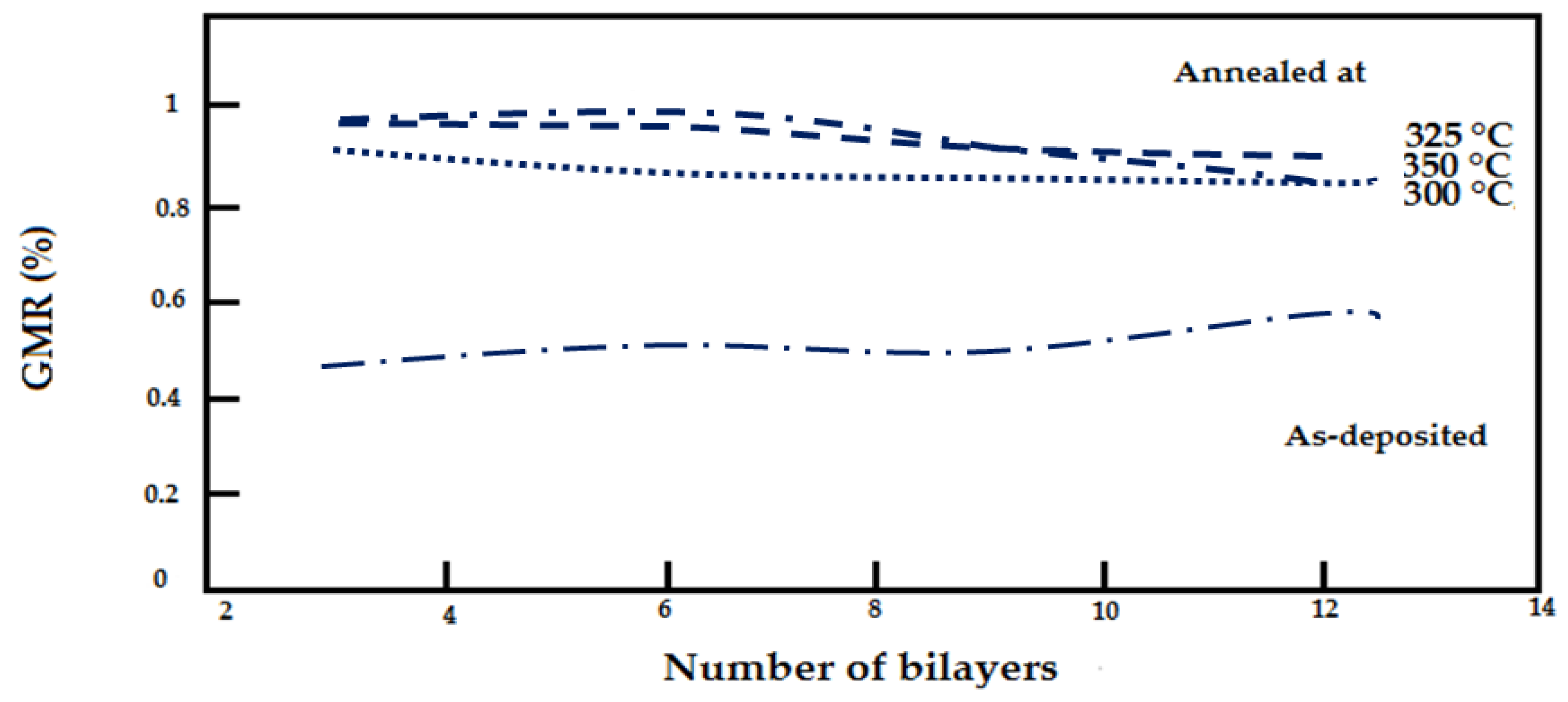
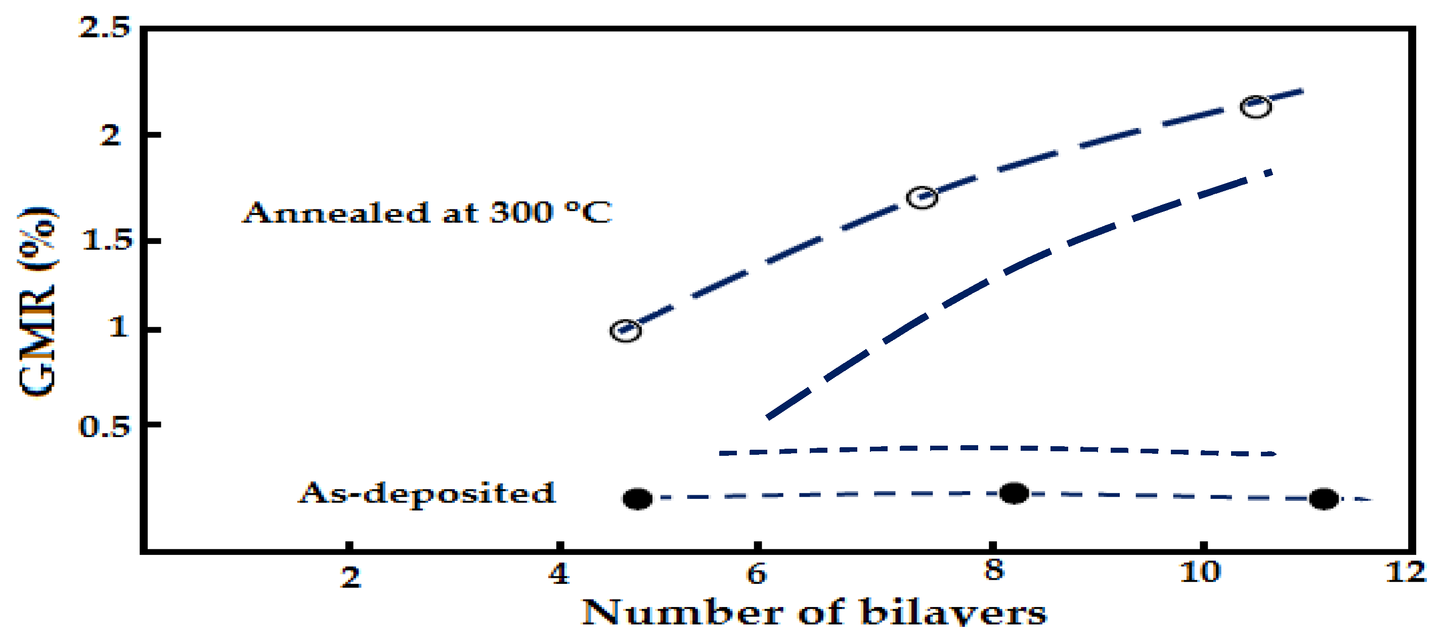
4.2. Thickness Structure Layers of Giant Magnetoresistance Sensor
4.3. Temperature
5. Factors Affecting the Eddy Current Testing Inspection
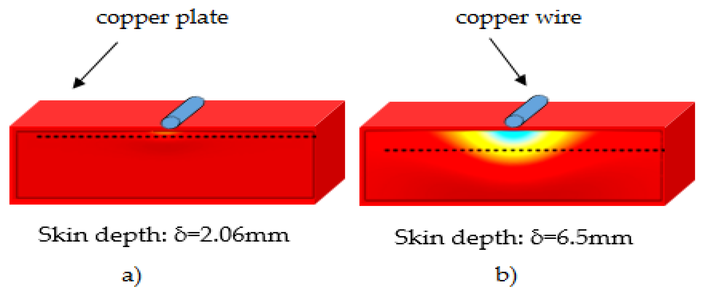
5.1. Exciting Coil Frequency and skin Depth Effect
5.2. Material Magnetic Permeability
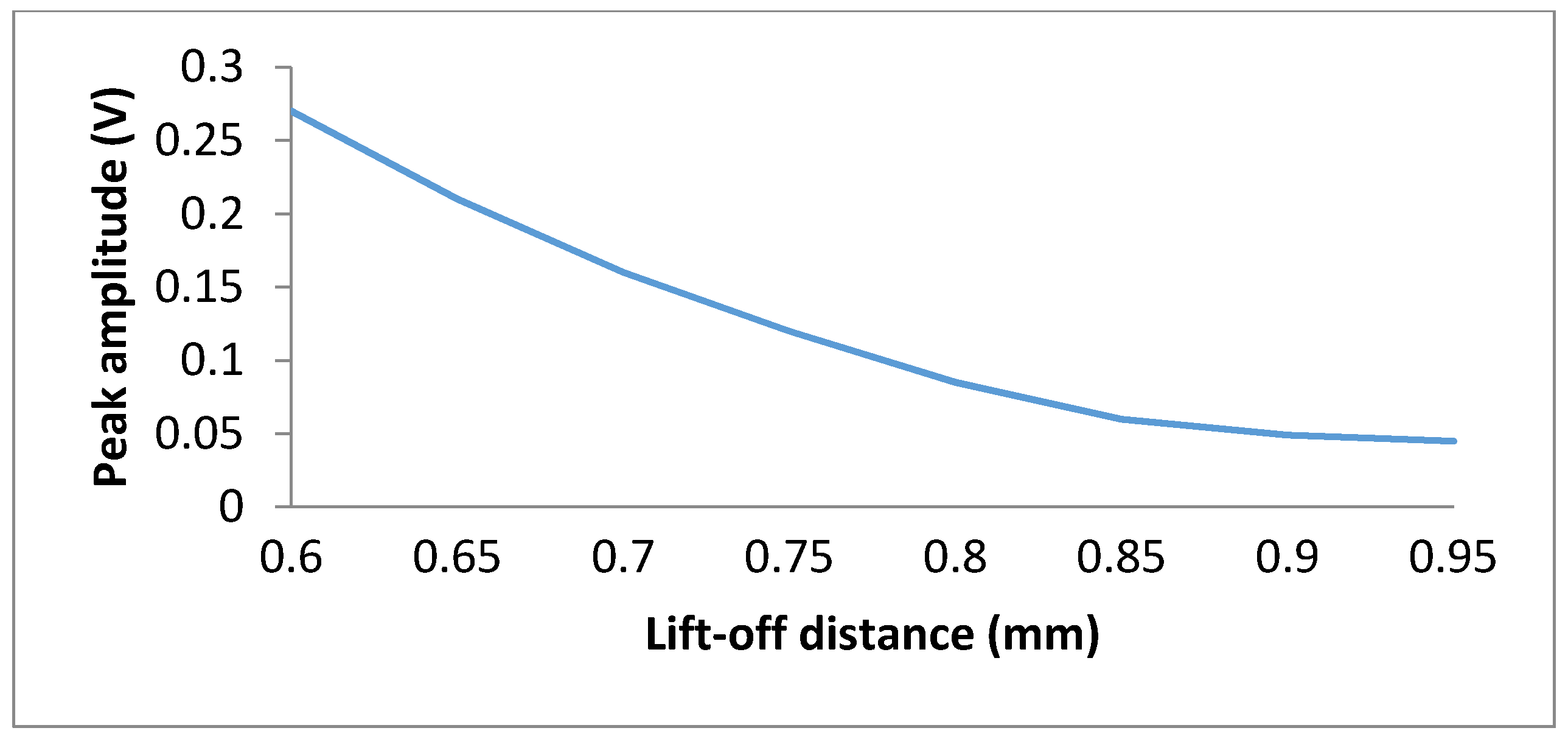
5.3. Lift-off
5.4. Conductivity of Material
5.5. Limitations of Coil Sensor in Eddy Current Probe
6. Compensation Techniques in Eddy Current Testing Probes
7. Application of GMR Sensors in Hybrid Eddy Current Testing Probes
8. Conclusions
Acknowledgments
Author Contributions
Conflicts of Interest
Abbreviations
| NDT | Non-destructive testing |
| ECT | Eddy current testing |
| GMR | Giant magnetoresistance |
| MR | Magnetoresistance |
| AFM | Antiferromagnetic |
| FM | Ferromagnetic |
| RPC | Rotating pancake coil |
| DAQ | Data acquisition, |
| NM | Non-magnetic |
| FEM | Finite element method |
| AC | Alternating current |
| DC | Direct current |
References
- Ghoni, R.; Dollah, M.; Sulaiman, A.; Ibrahim, F.M. Defect Characterization Based on Eddy Current Technique. Tech. Rev. 2014, 6. [Google Scholar] [CrossRef]
- Li, W.; Chen, G.; Yin, X.; Zhang, G.; Liu, T. Analysis of the lift-off effect of a U-shaped ACFM system. NDT&E Int. 2013, 53, 31–35. [Google Scholar]
- He, Y.; Pan, M.; Luo, F.; Tian, G. Pulsed eddy current imaging and frequency spectrum analysis for hidden defect nondestructive testing and evaluation. NDT&E Int. 2011, 44, 344–352. [Google Scholar]
- Biju, N.; Ganesan, N.; Krishnamurthy, C.V.; Balasubramaniam, K. Optimum frequency variations with coil geometry and defects in tone burst eddy current thermography (TBET). Insight Non-Destr. Test. Cond. Monit. 2013, 55, 504–509. [Google Scholar] [CrossRef]
- Abidin, I.; Umar, M.; Yusof, M. Advantages and Applications of Eddy Current Thermography Testing for Comprehensive and Reliable Defect Assessment. In Proceedings of the 18th World Conference on Nondestructive Testing, Durban, South Africa, 16–20 April 2000.
- Current, A.E.; Principle, T. Eddy Current Crack Extension Direction Evaluation based on Neural Network. In Proceedings of the 2012 IEEE conference on Sensors, Taipei, Taiwan, 28–31 October 2012; pp. 3–6.
- Hellier, C.J. Hanbook of Nondestructive Evaluation; McGraw-Hill Education: New York, NY, USA, 2012. [Google Scholar]
- García-Martín, J.; Gómez-Gil, J.; Vázquez-Sánchez, E. Non-destructive techniques based on eddy current testing. Sensors 2011, 11, 2525–2565. [Google Scholar] [CrossRef] [PubMed]
- Poon, T.Y.; Tse, N.C.F.; Lau, R.W.H. Extending the GMR current measurement range with a counteracting magnetic field. Sensors 2013, 13, 8042–8059. [Google Scholar] [CrossRef] [PubMed]
- Obeid, S. Giant Magnetoresistance Sensing Technologies for Detecting Small Defects in Metallic Structures. Ph.D. Thesis, University North Carolina, Chapel Hill, NC, USA, 2008. [Google Scholar]
- Jogschies, L.; Klaas, D.; Kruppe, R.; Rittinger, J.; Taptimthong, P.; Wienecke, A.; Rissing, L.; Wurz, M. Recent Developments of Magnetoresistive Sensors for Industrial Applications. Sensors 2015, 15, 28665–28689. [Google Scholar] [CrossRef] [PubMed]
- Mott, N.F. The Electrical Conductivity of Transition Metals. Proc. R. Soc. London Ser. A Math. Phys. Sci. 1936, 153, 699–717. [Google Scholar] [CrossRef]
- Baibich, M.N.; Broto, J.M.; Fert, A.; van Dau, F.N.; Petroff, F.; Etienne, P.; Creuzet, G.; Friederich, A.; Chazelas, J. Giant magnetoresistance of (001)Fe/(001)Cr magnetic superlattices. Phys. Rev. Lett. 1988, 61, 2472. [Google Scholar] [CrossRef] [PubMed]
- Dieny, S.N.B.; Speriosu, V.S.; Gurney, B.A.; Parkin, S.S.P.; Wilhoit, D.R.; Roche, K.P.; Metin, S. Spin-valve effect in soft ferromagnetic sandwiches J. Magn. Magn. Mater. 1991, 93, 101–104. [Google Scholar] [CrossRef]
- Prinz, G.A. Magnetoelectronics. Science 1998, 282, 1660–1663. [Google Scholar] [CrossRef] [PubMed]
- Nogués, J.; Schuller, I.K. Exchange bias. J. Magn. Magn. Mater. 1999, 192, 203–232. [Google Scholar] [CrossRef]
- Freitas, P.P.; Silva, F.; Oliveira, N.J.; Melo, L.V.; Costa, L.; Almeida, N. Spin valve sensors. Sens. Actuators A Phys. 2000, 81, 2–8. [Google Scholar] [CrossRef]
- Nolting, F.; Scholl, A.; Stohr, J.; Seo, J.; Fompeyrine, J.; Siegwart, H.; Locquet, J.; Anders, S.; Luning, J.; Fullerton, E.; et al. Direct observation of the alignment of ferromagnetic spins by antiferromagnetic spins. Nature 2000, 405, 767–769. [Google Scholar] [CrossRef] [PubMed]
- Kools, J.C.S. Exchange-biased spin-valves for magnetic storage. IEEE Trans. Magn. 1996, 32, 3165–3184. [Google Scholar] [CrossRef]
- Lenssen, K.M.H.; Adelerhof, D.J.; Gassen, H.J.; Kuiper, A.E.T.; Somers, G.H.J.; van Zon, J.B.A.D. Robust giant magnetoresistance sensors. Sens. Actuators A Phys. 2000, 85, 1–8. [Google Scholar] [CrossRef]
- Parkin, S.S.P. Giant Magnetoresistance in Magnetic Nanostructures. Annu. Rev. Mater. Sci. 1995, 25, 357–388. [Google Scholar] [CrossRef]
- Tsymbal, E.Y.; Pettifor, D.G. Perspectives of giant magnetoresistance. Solid State Phys. Adv. Res. Appl. 2001, 56, 113–237. [Google Scholar]
- Daughton, J.; Brown, J.; Chen, E.; Beech, R.; Pohm, A.; Kude, W. Magnetic field sensors using GMR multilayer. IEEE Trans. Magn. 1994, 30, 4608–4610. [Google Scholar] [CrossRef]
- Vieux-Rochaz, L. A new GMR sensor based on NiFe/Ag multilayers. Sens. Actuators A Phys. 2000, 81, 53–56. [Google Scholar] [CrossRef]
- Lee, J.; Jun, J.; Kim, J.; Choi, H.; Le, M. Bobbin-Type Solid-State Hall Sensor Array With High Spatial Resolution for Cracks Inspection in Small-Bore Piping Systems. IEEE Trans. Magn. 2012, 48, 3704–3707. [Google Scholar] [CrossRef]
- Cápová, M.S.K.; Cáp, I.; Janoušek, L. Recent trends in electromagnetic non-destructive sensing. Adv. Electr. Electron. Eng. 2008, 7, 322–325. [Google Scholar]
- Popa, R.C.; Miya, K.; Kurokawa, M. Optimized eddy current detection of small cracks in steam generator tubing. J. Nondestruct. Eval. 1997, 16, 161–173. [Google Scholar] [CrossRef]
- Bernieri, A.; Betta, G.; Rubinacci, G.; Villone, F. A measurement system based on magnetic sensors for nondestructive testing. IEEE Trans. Instrum. Meas. 2000, 49, 455–459. [Google Scholar] [CrossRef]
- Kim, Y.-Y.; Lee, S.-S. Eddy current probes of inclined coils for increased detectability of circumferential cracks in tubing. NDT&E Int. 2012, 49, 77–82. [Google Scholar]
- Lei, N.; Udpa, L.; Udpa, S.; Zeng, Z. Rotating field eddy current (RoFEC)-probe for steam generator inspection. Int. J. Appl. Electromagn. Mech. 2010, 32, 1279–1285. [Google Scholar]
- Thirunavukkarasu, S.; Rao, B.P.C.; Jayakumar, T.; Raj, B. Techniques for processing remote field eddy current signals from bend regions of steam generator tubes of prototype fast breeder reactor. Ann. Nucl. Energy 2011, 38, 817–824. [Google Scholar] [CrossRef]
- Obrutsky, L.S.; Sullivan, S.P.; Cecco, V.S. Transmit-Receive Eddy Current Probes. Available online: https://www.iaea.org/inis/collection/NCLCollectionStore/_Public/29/057/29057175.pdf (accessed on 18 November 2015).
- Sullivan, S.P.; Cecco, V.S.; Obrutsky, L.; Lakhan, R. Validating Eddy Current Array Probes for Inspecting Steam Generator Tubes. NDTnet 1998, 3, 29–35. [Google Scholar]
- Diercks, D. Steam generator tube integrity program. Nucl. Eng. Des. 1996, 165, 143–149. [Google Scholar] [CrossRef]
- Zaoui, A.; Menana, H.; Feliachi, M.; Berthiau, G. Inverse problem in nondestructive testing using arrayed eddy current sensors. Sensors 2010, 10, 8696–8704. [Google Scholar] [CrossRef] [PubMed]
- Xie, R.; Chen, D.; Pan, M.; Tian, W.; Wu, X.; Zhou, W.; Tang, Y. Fatigue Crack Length Sizing Using a Novel Flexible Eddy Current Sensor Array. Sensors 2015, 15, 32138–32151. [Google Scholar] [CrossRef] [PubMed]
- Jun, J.; Lee, J. Nondestructive evaluation of a crack on austenitic stainless steel using a sheet type induced current and a Hall sensor array. J. Mech. Sci. Technol. 2009, 22, 1684–1691. [Google Scholar] [CrossRef]
- Huo, S.; Wang, C.; Cheng, S.; Song, X. Impedance analyzing for planar eddy current probe array. In Proceedings of the International 2011 Conference on Information Science and Technology (ICIST), Nanjing, China, 26–28 March 2011; pp. 995–999.
- Heida, J.H.; Derk, J.P. Evaluation of non-destructive inspection methods for composite aerospace structures. NDT Prog. 2011, 2011, 1–12. [Google Scholar]
- Panayiotou, S.; Soper, A. Artificially intelligent 3D industrial inspection system for metal inspection. In Proceedings of the IEEE Southwest Symposium on Image Analysis and Interpretation, Dallas, TX, USA, 21–24 April 1994; pp. 130–135.
- Translation, I.; On, J.; In, M. Non-Destructive Testing with Magnetic Sensor Using Rotational Magnetic Flux. IEEE Trans. J. 1992, 7, 241–249. [Google Scholar]
- Enokizono, M.; Todaka, T.; Akita, M. Rotational Magnetic Flux Sensor with Neural Network for Non-destructive Testing. IEEE Trans. Magn. 1993, 29, 3195–3197. [Google Scholar] [CrossRef]
- Birring, A.S. Selection of NDT Techniques for Inspection of Heat Exchanger Tubing Conventional Eddy Current. ASNT Int. Conf. Pet. Ind. Insp. 1999, 6, 1–14. [Google Scholar]
- Wong, H.; Bajaj, V.; Moan, G.; Huterer, M.; Poidevin, C. The role of leak-before-break in assessments of flaws detected in CANDU pressure tubes. Int. J. Press. Vessel. Pip. 1990, 43, 23–37. [Google Scholar] [CrossRef]
- Fukutomi, H.; Takagi, T.; Nishikawa, M. Remote field eddy current technique applied to non-magnetic steam generator tubes. NDT&E Int. 2001, 34, 17–23. [Google Scholar]
- Alper, M.; Attenborough, K.; Hart, R.; Lane, S.J.; Lashmore, D.S.; Younes, C.; Schwarzacher, W. Giant magnetoresistance in electrodeposited superlattices. Appl. Phys. Lett. 1993, 63, 2144. [Google Scholar] [CrossRef]
- Petit, F.; Juraszek, J.; Youssef, J.B.; Teillet, J.; Dekadjevi, D.T.; le Gall, H. Effect of annealing on the structural and magnetic properties of giant magnetostrictive multilayers. J. Magn. Magn. Mater. 2005, 290–291, 839–842. [Google Scholar] [CrossRef]
- Parkin, S.S.P.; More, N.; Roche, K.P. Oscillations in Exchange Coupling and Magnetoresistance in Metallic Superlattice Structures: Co/Ru, Co/Cr, Fe/Cr. Phys. Rev. Lett. 1990, 64, 2304–2307. [Google Scholar] [CrossRef] [PubMed]
- George, J.; Pereira, L.; Barthélémy, A.; Petroff, F.; Steren, L.; Duvail, J.; Fert, A.; Loloee, R.; Holody, P.; Schroeder, P. Inverse spin-valve-type magnetoresistance in spin engineered multilayered structures. Phys. Rev. Lett. 1994, 72, 408–411. [Google Scholar] [CrossRef] [PubMed]
- Hossain, A.; Pirkle, H.; Parker, R. Design and fabrication of GMR multilayers with enhanced thermal stability. J. Magn. Magn. Mater. 1996, 156, 303–305. [Google Scholar] [CrossRef]
- Siritaratiwat, A.; Hill, E.; Stutt, I.; Fallon, J.; Grundy, P. Annealing effects on GMR multilayer films. Sens. Actuators A Phys. 2000, 81, 40–43. [Google Scholar] [CrossRef]
- Kral, J.; Smid, R. The Lift-off Effect in Eddy Currents Thickness Modeling and Measurement. Instrum. Meas. IEEE Trans. 2013, 62, 2043–2049. [Google Scholar] [CrossRef]
- Yadegari, A.M.; Moini, R.; Sadeghi, S.H.H.; Mazlumi, F. Output signal prediction of an open-ended rectangular waveguide probe when scanning cracks at a non-zero lift-off. NDT&E Int. 2010, 43, 1–7. [Google Scholar]
- Kral, J.; Smid, R.; Ramos, H.M.G.; Ribeiro, A.L. The lift-off effect in Eddy currents on thickness modeling and measurement. IEEE Trans. Instrum. Meas. 2013, 62, 2043–2049. [Google Scholar] [CrossRef]
- Xin, J.; Lei, N.; Udpa, L.; Udpa, S.S. Nondestructive Inspection Using Rotating Magnetic Field Eddy-Current Probe. IEEE Trans. Magn. 2011, 47, 1070–1073. [Google Scholar] [CrossRef]
- Xu, X.; Liu, M.; Zhang, Z.; Jia, Y. A Novel High Sensitivity Sensor for Remote Field Eddy Current Non-Destructive Testing Based on Orthogonal Magnetic Field. Sensors 2014, 14, 24098–24115. [Google Scholar] [CrossRef] [PubMed]
- Rifai, D.; Abdalla, A.N.; Razali, R. Investigating the Optimum Frequency and Gain for Calibration Copper Block Using Eddy Current Technique. In Proceedings of the 2015 International Conference on Smart Sensors and Application, Kuala Lumpur, Malaysia, 26–28 May 2015.
- Postolache, O.; Lopes, A.; Ramos, H.G. GMR array uniform eddy current probe for defect detection in conductive specimens. Measurement 2013, 46, 4369–4378. [Google Scholar] [CrossRef]
- Yin, W.; Withers, P.J.; Sharma, U.; Peyton, A.J. Noncontact characterization of carbon-fiber-reinforced plastics using multifrequency eddy current sensors. IEEE Trans. Instrum. Meas. 2009, 58, 738–743. [Google Scholar]
- Rifai, D.; Aizat, M.; Abdalla, A.N.; Afiq, A.; Amarul, M.; Ali, K. Non-destructive evaluation of depth of subsurface defects using Eddy Current Testing. Int. Acad. Conf. 2015, 3, 1–11. [Google Scholar]
- Morris, A.S.; Langari, R. Measurement and Instrumentation: Theory and Application; Butterworth-Heinemann: Oxford, UK, 2012. [Google Scholar]
- Rocha, T.J.; Ramos, H.G.; Ribeiro, A.L.; Pasadas, D.J.; Angani, C.S. Studies to optimize the probe response for velocity induced eddy current testing in aluminium. Measurement 2015, 67, 108–115. [Google Scholar] [CrossRef]
- Yang, G. Eddy Current Nondestructive Evaluation Using Magnetoresistive Sensing. Ph.D. Thesis, Michigan State University, East Lansing, MI, USA, 2013. [Google Scholar]
- Mook, G.; Hesse, O.; Uchanin, V. Typical Depths of penetration. Mater. Test. 2007, 49, 258–264. [Google Scholar] [CrossRef]
- Park, D.-G.; Angani, C.S.; Rao, B.P.C.; Vértesy, G.; Lee, D.-H.; Kim, K.-H. Detection of the Subsurface Cracks in a Stainless Steel Plate Using Pulsed Eddy Current. J. Nondestruct. Eval. 2013, 32, 350–353. [Google Scholar] [CrossRef]
- Chen, X.; Lei, Y. Excitation current waveform for eddy current testing on the thickness of ferromagnetic plates. NDT&E Int. 2014, 66, 28–33. [Google Scholar]
- Angani, C.S.; Park, D.G.; Kim, C.G.; Leela, P.; Kollu, P.; Cheong, Y.M. The Pulsed Eddy Current Differential Probe to Detect a Thickness Variation in an Insulated Stainless Steel. J. Nondestruct. Eval. 2010, 29, 248–252. [Google Scholar] [CrossRef]
- Dogaru, T.; Smith, S.T. Giant magnetoresistance-based eddy-current sensor. IEEE Trans. Magn. 2001, 37, 3831–3838. [Google Scholar] [CrossRef]
- Krampfner, Y.D.; Johsnon, D.D. Flexible substrate eddy current coil arrays. Rev. Prog. Quant. NDE 1988, 7, 471–478. [Google Scholar] [CrossRef]
- Chen, X.; Lei, Y. Time-domain analytical solutions to pulsed eddy current field excited by a probe coil outside a conducting ferromagnetic pipe. NDT&E Int. 2014, 68, 22–27. [Google Scholar]
- Rifai, D.; Abdalla, N.A.; Khamsah, N.; Ali, K.; Ghoni, R. Defect Signal Analysis for Nondestructive Testing. In Proceedings of the FluidsChR 2015, Langkawi, Malaysia, 25–27 November 2015.
- Bonavolontà, C.; Valentino, M.; Marrocco, N.; Pepe, G.P. Eddy Current Technique Based on HT c-SQUID and GMR Sensors for Non-Destructive Evaluation of Fiber/Metal Laminates. IEEE. Trans. Appl. Supercond. 2009, 19, 808–811. [Google Scholar] [CrossRef]
- Lu, J.; Huang, S.; Pan, K.; Qian, Z.; Chen, N. Development of characteristic test system for GMR sensor. In Proceedings of the 2012 8th IEEE Int. Symposium on Instrumentation and Control Technology, London, UK, 20–23 July 2012.
- Pelkner, M.; Neubauer, A.; Reimund, V.; Kreutzbruck, M.; Schütze, A. Routes for GMR-Sensor Design in Non-Destructive Testing. Sensors 2012, 12, 12169–12183. [Google Scholar] [CrossRef]
- Yin, W.; Binns, R.; Dickinson, S.J.; Davis, C.; Peyton, A.J. Analysis of the Liftoff Effect of Phase Spectra for Eddy Current Sensors. IEEE Trans. Instrum. Meas. 2007, 56, 2775–2781. [Google Scholar] [CrossRef]
- Tian, G.Y.; Li, Y.; Mandache, C. Study of lift-off invariance for pulsed eddy-current signals. IEEE Trans. Magn. 2009, 45, 184–191. [Google Scholar] [CrossRef]
- Xu, Z.; Wu, X.; Li, J.; Kang, Y. Assessment of wall thinning in insulated ferromagnetic pipes using the time-to-peak of differential pulsed eddy-current testing signals. NDT&E Int. 2012, 51, 24–29. [Google Scholar]
- Lopez, L.A.N.M.; Ting, D.K.S.; Upadhyaya, B.R. Removing Eddy-Current probe wobble noise from steam generator tubes testing using Wavelet Transform. Prog. Nucl. Energy 2008, 50, 828–835. [Google Scholar] [CrossRef]
- Tian, G.Y.; Sophian, A. Reduction of Lift-Off Effects for Pulsed Eddy Current NDT. NDT&E Int. 2005, 38, 319–324. [Google Scholar]
- Fan, M.; Huang, P.; Ye, B.; Hou, D.; Zhang, G.; Zhou, Z. Analytical modeling for transient probe response in pulsed eddy current testing. NDT&E Int. 2009, 42, 376–383. [Google Scholar]
- Safizadeh, S.; Hasanian, M. Gas Pipeline Corrosion Mapping Using Pulsed Eddy Current Technique. Int. J. Adv. Des. Manuf. Technol. 2011, 5, 11–19. [Google Scholar]
- Yang, S.; Tian, G.Y.; Abidin, I.Z.; Wilson, J. Simulation of Edge Cracks Using Pulsed Eddy Current Stimulated Thermography. J. Dyn. Syst. Meas. Control 2011, 133, 011008. [Google Scholar] [CrossRef]
- Theodoulidis, T.; Bowler, J.R. Interaction of an eddy-current coil with a right-angled conductive wedge. IEEE Trans. Magn. 2010, 46, 1034–1042. [Google Scholar] [CrossRef]
- Theodoulidis, T.; Bowler, J. Eddy-current interaction of a long coil with a slot in a conductive plate. IEEE Trans. Magn. 2005, 41, 1238–1247. [Google Scholar] [CrossRef]
- Huang, C. Probe Lift-off Compensation Method for Pulsed Eddy Current Thickness Measurement. In Proceedings of the 3rd Asia-Pacific Conference on Antennas and Propagation (APCAP), Harbin, China, 26–29 July 2014; pp. 937–939.
- Wu, Y.; Cao, Z.; Xu, L. A simplified model for non-destructive thickness measurement immune to the lift-off effect. In Proceedings of the Instrumentation and Measurement Technology Conference (I2MTC), Binjiang, China, 10–12 May 2011.
- Yin, W.; Member, S.; Xu, K. A Novel Triple-Coil Electromagnetic Sensor for Thickness Measurement Immune to Lift-Off Variations. IEEE Trans. Instrum. Meas. 2015, 65, 164–169. [Google Scholar] [CrossRef]
- Amineh, R.K.; Sadeghi, S.H.H.; Moini, R. Suppressing sensor lift-off effects on cracks signals in surface magnetic field measurement technique. IEEE Int. Conf. Ind. Technol. 2003, 2003, 360–363. [Google Scholar]
- He, Y.; Pan, M.; Luo, F.; Tian, G. Reduction of Lift-Off Effects in Pulsed Eddy Current for Defect Classification. IEEE Trans. Magn. 2011, 47, 4753–4760. [Google Scholar] [CrossRef]
- Yu, Y.; Yan, Y.; Wang, F.; Tian, G.; Zhang, D. An approach to reduce lift-off noise in pulsed eddy current nondestructive technology. NDT&E Int. 2014, 63, 1–6. [Google Scholar]
- Zhu, W.; Shen, H.; Chen, W. New Method for Suppressing Lift-Off Effects Based on Hough Transform. In Proceedings of the 2009.ICMTMA 09 International Conference on Measuring Technology and Mechatronics Automation, Zhangjiajie, Hunan, China, 11–12 April 2009; pp. 653–656.
- Chen, X.; Lei, Y. Electrical conductivity measurement of ferromagnetic metallic materials using pulsed eddy current method. NDT&E Int. 2015, 75, 33–38. [Google Scholar]
- Gotoh, Y.; Matsuoka, A.; Takahashi, N. Electromagnetic Inspection Technique of Thickness of Nickel-Layer on Steel Plate Without Influence of Lift-Off Between Steel and Inspection Probe. IEEE Trans. Magn. 2011, 47, 950–953. [Google Scholar] [CrossRef]
- Ribeiro, A.L.; Ramos, H.G.; Arez, J.C. Liftoff insensitive thickness measurement of aluminum plates using harmonic eddy current excitation and a GMR sensor. Measurement 2012, 45, 2246–2253. [Google Scholar] [CrossRef]
- Jedlicska, I.; Weiss, R.; Weigel, R. Increasing the measurement accuracy of GMR current sensors through hysteresis modeling. In Proceedings of the 2008 IEEE International Symposium on Industrial Electronics, Cambridge, UK, 30 June–2 July 2008; pp. 884–889.
- Bernieri, A.; Betta, G.; Member, S.; Ferrigno, L.; Laracca, M. Improving Performance of GMR Sensors. IEEE Sens. J. 2013, 13, 4513–4521. [Google Scholar] [CrossRef]
- Du, W.; Dutt, A.; Scallion, K. Design of a GMR sensor array system for robotic pipe inspection. In Proceedings of the 2010 IEEE Sensors, Kona, HI, USA, 1–4 November; pp. 2551–2554.
- Yang, G.; Zeng, Z.; Deng, Y.; Liu, X.; Udpa, L.; Dib, G. Sensor-tilt invariance analysis for eddy current signals. NDT&E Int. 2012, 52, 1–8. [Google Scholar]
- Gao, P.; Wang, C.; Li, Y.; Li, F.; Yan, Y. Defect Evaluation Using the Phase Information of an EC-GMR Sensor. In Proceedings of the Instrumentation and Measurement Technology Conference (I2MTC), Montevideo, Uruguay, 12–15 May 2014.
- Ramos, H.G.; Rocha, T.; Ribeiro, A.L.; Pasadas, D. GMR Versus Differential Coils in Velocity Induced Eddy Current Testing. In Proceedings of the Instrumentation and Measurement Technology Conference (I2MTC), Montevideo, Uruguay, 12–15 May 2014.
- Chao, W.; Ya, Z.; Peng, G. GMR Based Eddy Current System for Defect Detection. In Proceedings of the 2013 IEEE 11th International Conference on Electronic Measurement & Instruments (ICEMI), Harbin, China, 16–19 August 2013.
- Aguila-Munoz, J.; Espina-Hernandez, J.H.; Perez-Benitez, J.A.; Caleyo, F.; Hallen, J.M. Crack detection in steel using a GMR-based MFL probe with radial magnetization. In Proceedings of the 2013 International Conference on Electronics, Communications and Computing (CONIELECOMP), Cholula, Mexico, 11–13 March 2013; pp. 104–108.
- Postolache, O.; Ramos, H.G.; Ribeiro, A.L. Characterization of Defects in Aluminum Plates Using GMR Probes and Neural Network Signal Processing. Available online: https://www.researchgate.net/publication/228940556_Characterization_of_defects_in_aluminum_plates_using_GMR_probes_and_neural_network_signal_processing (accessed on 20 February 2015).
- Chen, W.; Zhao, Y.; Fan, J.; Zhang, X. Giant Magneto Resistance Based Eddy-Current testing system. 2014. [Google Scholar] [CrossRef]
- Postolache, O.; Ramos, H.G.; Ribeiro, A.L. Computer Standards & Interfaces Detection and characterization of defects using GMR probes and arti fi cial neural networks. Comput. Stand. Interfaces 2011, 33, 191–200. [Google Scholar]
- Yang, G.; Dib, G.; Udpa, L.; Tamburrino, A.; Udpa, S.S.; Eddy, A. Rotating Field EC-GMR Sensor for Crack Detection at Fastener Site in Layered Structures. IEEE Sens. J. 2015, 15, 463–470. [Google Scholar] [CrossRef]
- Ramos, H.G.; Rocha, T.; Král, J.; Pasadas, D.; Ribeiro, A.L. An SVM approach with electromagnetic methods to assess metal plate thickness. Measurement 2014, 54, 201–206. [Google Scholar] [CrossRef]
- Rosado, L.S.; Cardoso, F.A.; Cardoso, S.; Ramos, P.M.; Freitas, P.P.; Piedade, M. Sensors and Actuators A: Physical Eddy currents testing probe with magneto-resistive sensors and differential measurement. Sens. Actuators A. Phys. 2014, 212, 58–67. [Google Scholar] [CrossRef]
- Le, M.; Lee, J.; Kim, J. 2-D Vector Field Visualization of Corrosion in a Small-bore Piping System using Bobbin-type Integrated Hall and GMR Sensors Arrays. In Proceedings of the Sensors Applications Symposium (SAS), Queenstown, New Zealand, 18–20 February 2014; pp. 8–11.
- Hamia, R.; Cordier, C.; Dolabdjian, C. NDT & E International Eddy-current non-destructive testing system for the determination of crack orientation. NDT&E Int. 2014, 61, 24–28. [Google Scholar]
- Pasadas, D.J.; Ribeiro, A.L.; Rocha, T.J.; Ramos, H.G. Open Crack Depth Evaluation Using Eddy Current Methods and GMR Detection. In Proceedings of the Metrology for Aerospace (MetroAeroSpace), Benevento, Italy, 29–30 May 2014; pp. 117–121.
- Porto, R.W.; Brusamarello, V.J.; Azambuja, R. Design and analysis of a GMR eddy current probe for NDT. In Proceedings of the 2013 7th International Conference on Sensing Technology (ICST), Wellington, New Zealand, 3–5 December 2013; pp. 428–433.
- Smetana, M.; Strapacova, T. Detection capabilities evaluation of the advanced sensor types in Eddy Current Testing. Prz. Elektrotech. 2013, 89, 247–249. [Google Scholar]
- Zhao, J.; Tian, W.; Zhang, Q.; Pan, M.; Hu, J.; Chen, D.; Luo, F. Designs of Slope Magnetic Flux Guides for 3-Axis Magnetic Sensor. IEEE Trans. Magn. 2013, 49, 5301–5303. [Google Scholar] [CrossRef]
- Pasadas, D.; Rocha, T.J.; Ramos, H.G.; Ribeiro, A.L. Evaluation of portable ECT instruments with positioning capability. Measurement 2012, 45, 393–404. [Google Scholar] [CrossRef]
- Ribeiro, A.L.; Ramos, H.G.; Pasadas, D.J.; Rocha, T.J. Current around a crack in an aluminum plate under nondestructive evaluation inspection. In Proceedings of the 2012 IEEE International Instrumentation and Measurement Technology Conference (I2MTC), Graz, Austria, 13–16 May 2012; pp. 1635–1639.
- Davoust, M.-E.; Le Brusquet, L.; Fleury, G. Robust Estimation of Hidden Corrosion Parameters Using an Eddy Current Technique. J. Nondestruct. Eval. 2010, 29, 155–167. [Google Scholar] [CrossRef]
- Kim, J.; Yang, G.; Udpa, L.; Udpa, S. Classification of pulsed eddy current GMR data on aircraft structures. NDT&E Int. 2010, 43, 141–144. [Google Scholar]
- Cacciola, M.; Megali, G.; Pellicanó, D.; Morabito, F.C. A GMR–ECT based embedded solution for applications on PCB inspections. Sens. Actuators A Phys. 2011, 167, 25–33. [Google Scholar] [CrossRef]
- Tian, G.Y.; Sophian, A. Defect classification using a new feature for pulsed eddy current sensors. NDT&E Int. 2005, 38, 77–82. [Google Scholar]
- Rocha, T.J.; Ramos, H.G.; Ribeiro, A.L.; Pasadas, D.J. Magnetic sensors assessment in velocity induced eddy current testing. Sens. Actuators A Phys. 2015, 228, 55–61. [Google Scholar] [CrossRef]
- Ramírez, E.; Espina, J.H.; Pérez, J.A.; Caleyo, F.; Hallen, J.M. Some Particularities of EC Crack Detection in Aluminum Using an Asymmetrical GMR-Coil Configuration. IEEE Lat. Am. Trans. 2015, 13, 1331–1339. [Google Scholar] [CrossRef]
- Elshafiey, I.; Mohra, A. Evaluation of Printed Circuit Board. J. Circuits Syst. Comput. 2007, 16, 847–857. [Google Scholar] [CrossRef]
- Singh, W.S.; Rao, B.P.C.; Thirunavukkarasu, S.; Jayakumar, T. Flexible GMR Sensor Array for Magnetic Flux Leakage Testing of Steel Track Ropes. J. Sens. 2012, 2012, 129074. [Google Scholar] [CrossRef]
- Král, J.; Smid, R. Thickness Measurement Using Transient Eddy Current Techniques. In Proceedings of the Instrumentation and Measurement Technology Conference (I2MTC), Binjiang, China, 10–12 May 2011.
- Zeng, Z.; Deng, Y.; Liu, X.; Udpa, L.; Udpa, S.S.; Koltenbah, B.E.C.; Bossi, R.H.; Steffes, G. EC-GMR Data Analysis for Inspection of Multilayer Airframe Structures. IEEE Trans. Magn. 2011, 47, 4745–4752. [Google Scholar] [CrossRef]
- Tamburrino, A.; Udpa, L.; Udpa, S.S. Pulsed Eddy-Current Based Giant Magnetoresistive System for the Inspection of Aircraft Structures. IEEE Trans. Magn. 2010, 46, 910–917. [Google Scholar]


| Method | Principles | Application | Advantages | Limitation |
|---|---|---|---|---|
| Visual Testing | Uses reflected or transmitted light from test object that is image with the human eye or other light sensing device | Many application in many industries ranging from raw material to finished products and in-service inspection | Can be inexpensive and simple with minimal training required. Broad scope of uses and benefits | Only surface conditions can be evaluated. Effective source of illumination required. Access necessary |
| Penetrant Testing | A liquid containing visible or fluorescent dye is applied to surface and enters discontinuities by capillary action | Virtually any solid non-absorbent material having uncoated surfaces that are not contaminated | Relatively easy and materials are inexpensive. Extremely sensitive, very versatile. Minimal training | Discontinuities open to the surface only. Surface condition must be relatively smooth and free of contaminants |
| Magnetic Particle Testing | Test part is magnetized and fine ferromagnetic particle applied to surface, aligning at discontinuity | All ferromagnetic materials, for surface and slightly subsurface discontinuities; large and small parts | Relatively easy to use. Equipment/material usually inexpensive. Highly sensitive and fast compare to PT | Only surface and a few subsurface discontinuities can be detected. Ferromagnetic materials only |
| Radiographic Testing | Radiographic film is exposed when radiation passes through the test object. Discontinuities affect exposure | Most materials, shape, and structure. Examples include welds, castings, composites, etc... As manufactured or in service | Provides a permanent record and high sensitivity. Most widely used and accepted volumetric examination | Limited thickness based on material. Density, orientation of planar discontinuities is critical. Radiation hazard |
| Ultrasonic Testing | High frequency sound pulses from a transducer propagate through the test material, reflecting at interfaces | Most materials can be examine if sound transmission and surface finish are good and shape is not complex | Provide precise, high sensitivity results quickly. Thickness information, depth and type of flaw can be obtained from one side of component | No permanent record (usually). Material attenuation, surface finish and contour. Required couplant |
| Metal | %IACS | Resistivity Ω·m | Permeability | 36.8% Depth of Penetration | |||||
|---|---|---|---|---|---|---|---|---|---|
| 1 kHz | 4 kHz | 16 kHz | 64 kHz | 256 kHz | 1 MHz | ||||
| copper | 100 | 1.7 | 1 | 0.082 | 0.041 | 0.021 | 0.010 | 0.005 | 0.0026 |
| 6061 T-6 | 42 | 4.1 | 1 | 0.126 | 0.063 | 0.032 | 0.016 | 0.008 | 0.004 |
| 7075 T-6 | 32 | 5.3 | 1 | 0.144 | 0.072 | 0.036 | 0.018 | 0.009 | 0.0046 |
| Magnesium | 37 | 4.6 | 1 | 0.134 | 0.067 | 0.034 | 0.017 | 0.008 | 0.0042 |
| Lead | 7.8 | 22 | 1 | 0.292 | 0.146 | 0.073 | 0.37 | 0.018 | 0.0092 |
| Uranium | 6.0 | 29 | 1 | 0.334 | 0.167 | 0.084 | 0.042 | 0.021 | 0.0106 |
| Zirconium | 3.4 | 70 | 1.02 | 0.516 | 0.258 | 0.129 | 0.065 | 0.032 | 0.0164 |
| Steel | 2.9 | 60 | 750 | 0.019 | 0.0095 | 0.0048 | 0.0024 | 0.0012 | 0.0006 |
| Cast steel | 10.7 | 16 | 175 | 0.018 | 0.0089 | 0.0044 | 0.0022 | 0.0011 | 0.0006 |
| Material | Conductivity (% IACS) | Resistivity (µΩ/cm) |
|---|---|---|
| Aluminum bronze | 14.00 | 12.32 |
| Aluminum 7075-T6 | 32.00 | 5.39 |
| Aluminum 2024-T4 | 30.00 | 5.20 |
| Aluminum 6061 | 42.00 | 4.10 |
| Brass | 28.00 | 6.20 |
| Copper nickel 70–30 | 4.60 | 37.48 |
| Copper | 100.00 | 1.72 |
| Gold | 70.00 | 2.46 |
| Monel | 3.60 | 47.89 |
| Copper nickel 90–10 | 9.10 | 18.95 |
| Cast Steel | 10.70 | 16.02 |
| Hastelloy-X | 1.50 | 115.00 |
| Inconel 600 | 1.72 | 100.00 |
| Lead | 8.35 | 20.65 |
| Magnesium | 38.60 | 4.45 |
| Phosphor bronze | 11.00 | 16.00 |
| Silver | 105.00 | 1.64 |
| Stainless Steel 316 | 2.33 | 74.00 |
| Stainless Steel 304 | 2.39 | 72.00 |
| Sodium | 41.50 | 4.20 |
| Ti-6AI-4V | 1.00 | 172.00 |
| Titanium-2 | 3.55 | 48.56 |
| Tungsten | 30.51 | 5.65 |
| Zirconium | 4.30 | 40.00 |
| Zircalloy-2 | 2.40 | 72.00 |
| Ref. | Research Area | Compensation Techniques |
|---|---|---|
| [85] | To remove the lift-off effect in PEC ferromagnetic material test piece inspection | Relative magnetic flux changing rate |
| [86] | Presented a simple model for metal thickness measurement that unaffected by lift-off effect. | Signal analysis base on multi-frequency phase signature |
| [87] | Developed ECT system based on three coils exciting coils to measure the plate thickness | Data analysis using peak frequencies of the sensor signal to estimate the thickness of the plate |
| [88] | Proposed a method for suppressing of lift-off effect in SMFM system | Signal deconvolution |
| [89] | Proposed ECT system with rectangular sensor configuration and time domain analysis and frequency domain analysis for defect classification. | Time domain analysis and frequency domain analysis |
| [90] | Proposed a method to reduce the lift-off effect in PEC deep defect measurement | Measure the defect dimension base on slope of the linear curve of the peak value difference sensor signal |
| [91] | Investigate the lift-off effect in the normalized impedance plane | Hough transform |
| [92] | Developed PECT system for ferromagnetic material electrical conductivity measurement | Mathematical model |
| [89] | Investigated the feature extraction techniques for PEC defect classification | Signal differential analysis |
| [93] | Developed ECT system to measure the thickness of nickel layer | 3-D edge-based hexahedral nonlinear FEM |
| [79] | Investigated the effect of lift –off in PEC non-destructive testing | Normalization and two-stage operative process |
| [94] | Construct a system to measure the thickness of metal plates | Lift-off points of interception |
| Author | Reseach Area | Signal Analysis Tool/Software Simulation | Observations |
|---|---|---|---|
| [103] | Defect classification in aluminium plate test pieces | Neural Network Processing | Probe optimization and defect classification using limited defect features. |
| [95] | To increase the accuracy of the GMR sensor by numerically compensating the hysteresis effect | Finite Impulse Response | Strongly reduced the hysteresis and optimized the probe design by increasing the speed of inspection |
| [104] | Optimize the eddy current testing probe for subsurface tiny crack defect inspection | Maxwell design simulation | The system is able to detect tiny defect cracks of up to 3 mm under the surface. Experimental results prove the main source of noise is the current excitation frequency. |
| [97] | Developed an eddy current testing probe based on an array of GMR sensors for pipe inspection | Fast Fourier Transformation | The array of GMR sensors is able to detect various types of defect. The signal output of the array sensor can be used to classify and define the properties of different defects. |
| [105] | Designed and construct an automatic eddy current system for inspection of an artificial straight defect in an aluminium plate. | Neural network/multilayer perceptron/competitive neural network/finite element simulation | Implementation of the neural network classification technique increases the accuracy of defect classification |
| [106] | Designed and developed an eddy current testing probe using a rotating exciting magnetic field for detection of radial cracks around a fastener | Finite element model simulation | The eddy current testing probe current shift exciting magnetic field is 90° in phase. The simulation and experimental results show the system is able to detect all orientations of a defect under the fastener |
| [107] | Developed an ECT system to classify multiple classes of defect thickness in conductive plates. | Support vector machine—SVM | The system successfully classified the thickness defect with an error lower than 1.52%. |
| [99] | Investigated the defect properties based on the phase signal of a GMR sensor | Finite element method (FEM) program | The experimental results proved the phase signal output of the GMR sensor provides more defect information. |
| [108] | Developed an ECT probe for surface defect inspection. | - | The probe was able to detect and measure an artificial defect with a dimension of 0.15 mm width and 0.2 mm depth. |
| [100] | Investigated the efficiency of defect detection using a differential pick-up coil and GMR sensor | - | Both sensors were able to detect defects with thicknesses of more than 1 mm. The GMR sensor detects the defect when the sensing direction crosses the edge defect while the pick-up coil needs the whole magnetic field to cross the defect to detect it. |
| [109] | Designed a 2-D magnetic field camera system to measure the properties of the magnetic field around inner and outer defects in a piping system | - | The system is able to sense the magnetic field in the radial and axial direction. |
| [110] | Proposed a method for deep subsurface defect inspection. | Finite Element Method (FEM) | Experimental and simulation show the system is able to detect deep subsurface defects |
| [111] | Investigated defect signals of an artificial rectangular straight defect in aluminium plates. | - | The experiments showed the direction of the defect is easy to detect if the defect is crossing the magnetic field. |
| [101] | Designed an ECT system based on a GMR sensor and a Field Programmable Gate Array (FPGA) as controller | Fourier Transform analysis | The system able to display the defect signals in amplitude and phase mode. A signal demodulation function has been realized for defect characteristic analysis. |
| [96] | Developed a low-cost ECT system with an automatic calibration system to reduce the uncertainty of GMR sensor measurement. | Static (DC) and dynamic (AC) analysis | The system is capable of inspecting defects using DC and AC exciting magnetic fields with a high percentage of accuracy |
| [112] | Developed an ECT system based on a GMR sensor for surface defect inspection | Polynomial regression | The system scans the defect in the direction of the sensor sensitive scanning area for accurate measurement. |
| [58] | Designed and optimized an ECT probe based on two planar excitation coils and a rectangular magnetic field biasing architecture | LabVIEW/sum squared difference (SSD) and normalized cross correlation (NCC) | Improved the inspection capabilities of the ECT probe with fast scanning time |
| [102] | Developed an ECT probe with radial magnetization | - | The 50° angle axis sensitivity of the GMR sensor to the defect orientation reduces by 28% the average value of the VD parameter |
| [113] | Investigated the performance of magnetic detection in an ECT probe for non-destructive inspection. | Numerical simulations | The results show a GMR sensor is better compared to the coil detector in term of sensitivity and dimensions. |
| [114] | Designed and modeled a magnetic field based on guide magnetic slopes | Finite element method (FEM) | The experimental results show the GMR sensor is sensitive only to the z-component of the magnetic field. |
| [94] | Implementation of an ECT to measure the thickness of metallic plates | - | The experiments show a frequency of 250 Hz is the optimum excitation coil frequency for maximum depth magnetic field penetration in the metal plate |
| [115] | Developed an ECT inspection systems using a GMR sensor | - | The system has the ability to inspect subsurface cracks at frequencies lower than 3.3 kHz |
| [74] | Investigated the optimal arrangement of a GMR sensor for optimum defect inspection. | Analytical model | The analysis shows the length and height of the GMR sensor influence signal strength loss by up to 10% a in 250 µm defect baseline |
| [116] | Investigated the characteristics of the current around an artificial crack for defect geometry identification | Fast Fourier transform/Tikhonov regularization algorithm | Characteristics of the current show a significant pattern with different geometry of cracks. |
| [98] | Proposed a novel invariance analysis for ECT signals in deep subsurface defects under fastener heads | Finite Element (FE) | Presented a reliable ECT inspection technique for different sizes and geometries of cracks under fastener heads. |
| [117] | Proposed an ECT system for inspection of hidden corrosion defects. | FEM | The inspection results show high accuracy with mean errors of less than 2% |
| [118] | Developed a PEC–GMR system for ECT non-destructive testing | Principal component analysis and the k-means algorithm | The system is capable of detecting cracks with a size of 1 mm located up to 10 mm subsurface |
| [119] | Developed an ECT–NDT system based on (GMR) sensors for circuit board (PCB) inspection | COMSOL Multiphysics | The system is capable of detecting and characterizing the type of defect track narrowing, circular holes and track dilatation. |
| [120] | Developed a general procedure for ECT defect sizing and classification in multilayered structures | Partial least squares (PLS)/kernel partial least squares (KPLS) | The KPLS regression method gives a better prediction performance compared to the PLS regression method |
| [121] | Proposed a novel ECT technique based on the induced velocity of eddy currents | Numerical model | The proposed method increases the sensitivity and the depth defect detection of the system. |
| [122] | Investigated the optimum asymmetrical coil-GMR configuration for surface defect inspection | - | The experimental results demonstrated that the intermediate peak does not have any influence on DV value with the depth of defects |
| [123] | Analyzed the sensitivity of GMR sensors and GMI sensors in detecting the magnetic field | Finite Element/Moments analysis | The experimental and modeling results show the GMR and GMI sensors are able to detect the changes of orientation of a magnetic field excited by using AC and DC current sources |
| [54] | Investigate the effect of lift-off in metallic plate thickness measurement | Linear Transformer Model/experimental | The lift-off, material conductivity and the plate thickness have a significant influence on the measurement of metallic plate thickness |
| [124] | Developed an ECT system based on a GMR sensor array for outer steel rope track defect inspection. | Finite element model | The experimental results reveal that the ECT system is able to detect both of LF and LMA type defects in the rope track. |
| [55] | Proposed a novel design of a rotating magnetic field ECT for SG tubes. | Finite Element modeling | The simulation and experimental results show that the probe is sensitive to defects in ferromagnetic and non-ferromagnetic tubes. |
| [125] | Investigated the performance of the PEC technique in material thickness measurement | Experimental | The method was verified experimentally to be suitable for material thickness measurement since the PEC method has deep magnetic penetration. |
| [126] | Enhanced the sensitivity of the ECT-GMR system using analysis of two signal GMR sensors | (3-D) Finite Element Mesh | Simulation results show that the proposed method improved significantly the sensitivity of the system in detection of multilayer subsurface defects |
| [127] | Developed an ECT-GMR system for inspection of defects under fasteners in airframe structures | Time domain and frequency domain features | Experimental results demonstrate the feasibility of the proposed approach for the detection of simulated cracks (less than 1 mm length) that are buried 4 mm deep in the second layer |
© 2016 by the authors; licensee MDPI, Basel, Switzerland. This article is an open access article distributed under the terms and conditions of the Creative Commons by Attribution (CC-BY) license (http://creativecommons.org/licenses/by/4.0/).
Share and Cite
Rifai, D.; Abdalla, A.N.; Ali, K.; Razali, R. Giant Magnetoresistance Sensors: A Review on Structures and Non-Destructive Eddy Current Testing Applications. Sensors 2016, 16, 298. https://0-doi-org.brum.beds.ac.uk/10.3390/s16030298
Rifai D, Abdalla AN, Ali K, Razali R. Giant Magnetoresistance Sensors: A Review on Structures and Non-Destructive Eddy Current Testing Applications. Sensors. 2016; 16(3):298. https://0-doi-org.brum.beds.ac.uk/10.3390/s16030298
Chicago/Turabian StyleRifai, Damhuji, Ahmed N. Abdalla, Kharudin Ali, and Ramdan Razali. 2016. "Giant Magnetoresistance Sensors: A Review on Structures and Non-Destructive Eddy Current Testing Applications" Sensors 16, no. 3: 298. https://0-doi-org.brum.beds.ac.uk/10.3390/s16030298