Enabling Autonomous Navigation for Affordable Scooters


Computer Engineering, San Jose State University, San Jose, CA 95123, USA
*
Author to whom correspondence should be addressed.
Sensors 2018, 18(6), 1829; https://0-doi-org.brum.beds.ac.uk/10.3390/s18061829
Submission received: 1 April 2018
/
Revised: 19 May 2018
/
Accepted: 21 May 2018
/
Published: 5 June 2018
(This article belongs to the Section Physical Sensors)
Abstract
:Despite the technical success of existing assistive technologies, for example, electric wheelchairs and scooters, they are still far from effective enough in helping those in need navigate to their destinations in a hassle-free manner. In this paper, we propose to improve the safety and autonomy of navigation by designing a cutting-edge autonomous scooter, thus allowing people with mobility challenges to ambulate independently and safely in possibly unfamiliar surroundings. We focus on indoor navigation scenarios for the autonomous scooter where the current location, maps, and nearby obstacles are unknown. To achieve semi-LiDAR functionality, we leverage the gyros-based pose data to compensate the laser motion in real time and create synthetic mapping of simple environments with regular shapes and deep hallways. Laser range finders are suitable for long ranges with limited resolution. Stereo vision, on the other hand, provides 3D structural data of nearby complex objects. To achieve simultaneous fine-grained resolution and long range coverage in the mapping of cluttered and complex environments, we dynamically fuse the measurements from the stereo vision camera system, the synthetic laser scanner, and the LiDAR. We propose solutions to self-correct errors in data fusion and create a hybrid map to assist the scooter in achieving collision-free navigation in an indoor environment.
1. Introduction
Technology holds great promise to make life better for the elderly and people with disabilities, for example, the blind. The number of United States residents age 70 and older is projected to increase to 53.7 million by 2030, from 30.9 million in 2014 [1]. It is also estimated that over one million persons in the U.S. are blind, and each year 50,000 more will become blind [1]. The “mobility challenge” which we address in this project, centers on one’s ability to independently move through the world. Enabling individuals to maintain their independence of mobility is of significant social importance.
Mobility scooters are becoming an increasingly common sight in many places, for example, shopping malls, supermarkets, visitor centers, hospitals, and at some tourist attractions. However, despite their prevalence, operating the scooter is still challenging in many places, for example, indoor crowded areas with narrow spaces, dead ends, and sidewalks without a ramp. More often than not, people with mobility challenges have to rely on their own sense of surroundings, hoping that their path is clear so they will not hit obstacles along the way. However, scooters are low to the ground, so their riders are often unable to clearly see some of the obstacles around them or under unfamiliar route conditions. As a result, people with disabilities, for example, the blind, often cannot safely drive these mobility scooters and are therefore unable to achieve sufficient mobility independence.
Sensor and autonomous technologies can transform the scooter safety and convenience not only for existing riders, but they can also make mobility possible for the elderly and people with disabilities who have so far been constrained from driving scooters altogether. An intelligent mapping system is essential to provide a high-resolution understanding of the real physical world with dynamic obstacle avoidance. A variety of sensing and mapping technologies have been proposed for the autonomous navigation application scenarios, for example, Ultrasound-based [2,3], LiDAR-based, and vision-based approaches [4,5,6]. Microsoft’s Kinect and Google’s Project Tango Tablet Development Kit are two famous vision-based development platforms. Though these systems have many advantages, they also have their downsides. Vision-based depth information obtained in regions exposed to sunlight or covered by high reflective materials (i.e., tiles and glass doors) do not allow for an accurate measurement of depth. In addition, if the scene is featureless, for example, white walls with uniform texture, not enough features are detected for estimation of visual odometry. One other situation when such problems can happen is in large environments where only a small area near the camera has depth readings and the other area is too deep, for example, in corridors and hallways. Self-driving cars from Google and Uber heavily rely on the Velodyne LiDAR for their 3D mapping. The personal mobility scooter developed in [7] also utilizes this kind of LiDAR. However, the existing 3D LiDAR devices are bulky and expensive at a minimum of $10,000 per unit, which is not suitable for small and affordable mobility scooters (around each). The performance of current low-cost LiDAR modules can only achieve coverage of several meters [8], which is not efficient enough to navigate a scooter through small scale spaces or avoid “on-road” dynamic obstacles, therefore lacking in convenience and resilience.
In this paper, we propose to develop an intelligent and affordable autonomous scooter that assists people with unique transportation challenges to travel in previously unmapped surroundings (for example, shopping in stores without assistance) with independence and dignity. Existing LiDAR and multi-camera devices used in outdoor self-driving cars are too bulky and expensive for the scooter. A small safety margin along with highly dynamic pedestrian walking patterns create more challenges than outdoor roads in terms of mobility. We propose to design and implement a new hybrid far-field and near-field mapping solution, targeting various cases from near-field fine-grained resolution to long range sparse coverage. To improve the resilience of the mapping, we propose a location-constrained hybrid 2D and 3D map fusion approach that can interconnect interrupted 3D maps. This design makes the mapping sensing extremely flexible and cost-effective for various navigation scenarios.
Section 2 will discuss the overview of the scooter design; Section 3 will illustrate our indoor localization approaches via Ultra-Wideband (UWB); Section 4 will discuss the detailed approaches in mapping and obstacle detection. The system evaluation results are discussed in Section 5. Section 6 concludes this paper.
2. System Overview
To support our proposed representative use case and provide spatial-aware and intelligent assistance services for people with mobility challenges, we design the autonomous scooter as illustrated in this section.
2.1. System Module Design for the Scooter
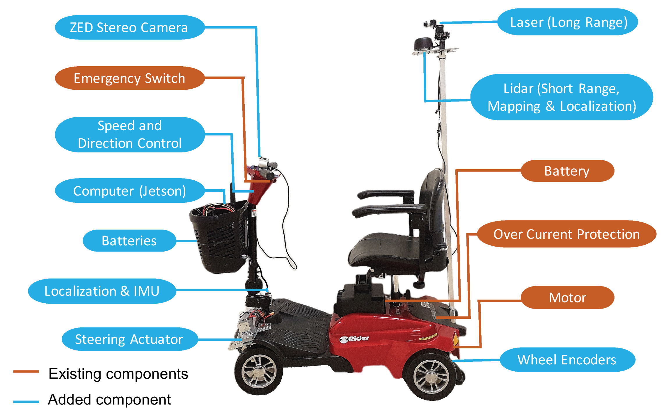
Scooter Architecture. To achieve an affordable design, we built an autonomous system based on the off-the-shelf mobility scooter ( model) and installed additional low-cost hardware and computing modules to enable the speed/direction control, automatic steering, and autonomous navigation features. As shown in Figure 1, the total bill-of-material (BOM) price of the autonomous scooter has been controlled within including the scooter.
Steering Control. To achieve the automatic steering control of the scooter, we install additional motors to control the steering wheel, speed, and direction. As shown in Figure 2, we made a few vendor-independent modifications in the mobility scooter to automate the steering control. We used a linear actuator (capable of 25 lb thrust with 4-inch movements) to push and pull the steering rod to the desired steering angle. This mechanism achieves better torque with simple installation than the servo motor. However, a major disadvantage of this mechanism is that the linear actuator has a higher error in linear actuation when compared with the precision servo motor. The same input to the linear actuator cannot promise the same position of the scooter.
To improve the control accuracy, a Proportional Integral Derivative (PID) controller has been used to actuate and turn the steering to the desired angle step-by-step with high degree accuracy. We utilize the Inertial Measurement Unit (IMU) to measure the actual angle and drive the linear actuator according to the angle differences. We mount the MPU-9250 sensor on the steering rod in the x-y plane. The angle can be calculated via , where are sensor readings from the accelerometer in x, y, z directions. This mechanism ensures the scooter moving to the desired direction and reduces the chances of under-steering or over-steering. In the case of interruptions or road obstacles, for example, when the wheels tend to turn because of uneven road conditions, the PID and feedback loop would help the actuator to pull the steering back to its original direction in a short interval.
Speed/direction Control. The original mobility scooter has a fuse to limit the current from the power supply in order to maintain the legal speed limit of 5 mph. The output analog voltage from the potentiometer controls the speed. A similar control has been used for direction control: a voltage beyond 2.5 v drives the mobility scooter in the reverse direction and a voltage below 2.5 v drives it in the forward direction. There is another internal fuse located on the control circuit which limits the scooter from turning on if the throttle is not at the zero position. Due to this mechanism, we could not hack the controller by changing the supply of the analog signal without bypassing the fuse. Otherwise, the current of the control signal may likely exceed the limit of the fuse and cause problems. We propose to obtain the speed/direction control without breaking into the internal circuits. Specifically, we use two 7.4 v precision servo motors (capable of delivering a maximum of 10 N-m torque) to control the potentiometer by rotating its head without bypassing the fuse. This design can be applied to other vendor’s mobility scooters with minimal changes.
2.2. Computing and Human Interface
Computing Module. All Tesla vehicles—Model S, Model X, and the upcoming Model 3—will be equipped with an on-board “supercomputer-based” NVIDIA DRIVE PX2 that can provide full self-driving capability. However, NVIDIA was selling DRIVE PX2 development kits for $15,000. To ensure the modular and affordable design of the hardware, we propose to design our own hardware and interface to NVIDIA Embedded GPU module (Jetson) to meet our needs. Although the Jetson has less number of GPU cores, while the DRIVE PX2 has two Tegra X2 (Parker) and two Pascal GPU. However, the chip in Jetson TX2 is based on the same Tegra chip used in the NVIDIA Drive PX2 platform, which uses TSMC’s automotive grade 16 nm FinFET process. Jetson has a much higher performance to price ratio than the DRIVE PX2.
The design architecture of our computing module is shown in Figure 3. Our fabricated hardware is shown in Figure 4 with unit BOM cost around $300. We utilize a low-power, low-cost FPGA as the sensor hub, clock management, logic and connection glue. Unlike traditional FPGAs that are high-cost, high-speed and high-power consumption, the latest Lattice FPGA (ICE5LP4K) is low-power, low-cost, and flexible, and equipped with hardcore I2C/SPI interface and DSP unit. We use this FPGA to glue multiple radio chips, audio components, sensor modules, and extension ports together. This design can help the designer select chips and connections for different applications, while keeping the rest of the chips in sleep. Another key advantage is that our FPGA can manage the extension ports and make them connectable with existing multiple open source computing boards, for example, the Nvidia Jetson TX2 module, Raspberry Pi, and Arduino. In this project, we make it directly connectable with the Nvidia Jetson TX2, which will serve as the edge computing unit. The Jetson TX2 runs Ubuntu 16.0.4 with ROS Kinetic. Most of the programs run on ROS platform are written in python or C. To enable the open and easy development of the human interface module, we utilize an Android tablet as the front-end device.
2.3. Sensing and Mapping Module
Depth perception is the ability to perceive the world in three dimensions. It can be done using various cues such as binocular cues and monocular cues. Existing obstacle detection solutions [2,3] can provide an alert for obstacles present in the area scanned by an ultrasound sensor (<1 m in front of the user’s feet). Some authors use the RGB-D camera to obtain 3D information of the surrounding environment [9,10]. Based on the ego-motion tracking within the Tango, the author [5] proposed localization alignment on the semantic map, obstacle detection, and safe path generation to the desired destination. Several researchers also presented novel robotic walkers, designed primarily for elderly people with walking disabilities [6]. Though these systems have many advantages, they also have their downsides. First, environmentally sensitive: The stereo camera system calculates depth via epipolar geometry, and the RGBD camera registers depth via an infrared (IR) sensor. Compared with the stereo system, the IR sensor does not involve any expensive algorithm in estimating the depth. However, vision-based approaches do not work well under indoor complex environment, for example, various lighting conditions, deep hallway, group reflection, uniform background, windows and glasses. Second, limited range: The maximum coverage of the depth sensor in Kinect is only 4 m, which is significantly shorter than a human’s vision. Project Tango brings a new kind of spatial perception by adding a hybrid infrared (IR) sensor and stereo vision. However, it only works best indoors at moderate distances (0.5 to 4 m). Third, expensive hardware and bulky device: LiDAR sensors can cover longer ranges with better accuracy than infrared and the stereo vision. However, the expensive commercial LiDAR mapping system is not suitable for the affordable scooter scenario either in terms of economical or practical points of view. Forth, high computational power: The precise recognition of the “on-road” dynamic obstacles based on LiDAR or vision requires high computational power. Another practical challenge is that the autonomous system does not know its global position and the sensed map is only for the local region. A significant amount of computation is utilized to localize the previous maps, i.e., the multi-session graph-based mapping problem [11]. How to quickly localize itself in a map and how to combine the newly created map with the previously-built map efficiently are important challenges.
Inspired by the human brain, which can efficiently select the best cue for depth perception based on scene, we propose to utilize the long range eye safe laser ranging (up to 60 m) to approximate a human’s vision coverage and use stereo vision to help recognize the fine-grained world around them. The sensing module is shown in Figure 2c. Different from LiDAR, laser ranging only works for a single point coverage and suffers under strong vibration by the motions. Instead of just using a single sensor for mapping, our proposed sensor fusion solution will help solve the uniform background problem of the vision sensor, improve the coverage of the LiDAR, and minimize mapping mismatches.
3. Scalable Indoor Localization
Location sensing is one of the fundamental technological building blocks towards intelligent and autonomous applications. In this paper, we focus on improving the quality of network and localization services via smart indoor infrastructure, which is similar to the outdoor roadside unit (RSU).
3.1. Background
Accurate approaches rely on the deployment of additional infrastructure [12,13], for example, dense anchor nodes. Existing accurate approaches require proper GDOP (geometric dilution of precision) of the infrastructure coverage [13], for example, deploying at least three nodes around the area of interest for trilateration. However, many real-world scenarios present significant constraints in terms of the number of nodes deployed and the geometric distribution of the nodes. The achieved localization accuracy drops significantly when the number of accessed anchor nodes is less than four; it is even unlocalizable with less than three nodes. However, in many real cases, there will be less than three nodes accessed. Thus, the accuracy, coverage and quality of location services deteriorate significantly and even stop working in real-world environments.
3.2. Multi-Modal Location Sensing
To solve localization challenges and minimize the deployment cost of existing infrastructure-based solutions, we propose to utilize our own hardware as the indoor infrastructure with multi-modal sensors, various protocols, and multiple service offerings. The key advantage of our solution is the relaxed requirements of deployment: sparse deployment with minimized position preference. To leverage the hardware module in Figure 4, we utilize the same hardware (without the external Jetson) in the autonomous scooter as the infrastructure node. The main features for this design fall into the following four parts: (1) Multi-modal beacons: Instead of only using one type of signal as the location beacon, we add an Impulse Radio-Ultra-wideband (IR-UWB) chip for a high timing (nano-second level) and ranging solution (∼15 cm). This chip can perform ranging even under none-line-of-sight (NLOS) environment. The maximum coverage is around 200 m. This chip is a significant add-on; (2) Robust coverage: We also utilize the inertial measurement unit (IMU) and wheel encoder to capture the relative motion. When there is no UWB coverage, we will utilize the IMU and wheel encoder to estimate the displacement. To lower the required number of anchor nodes, we propose random user phase-level mobility tracking via IR-UWB four-way differential messaging. When the user moves, the clock of the user’s device will be tracked at the phase level and automatically adjusted to sync the remote anchors, which reduces additional synchronization node; (3) Multi-user scalability: The key challenge caused by four-way IR-UWB differential messaging is the limited multi-user capability. Every time a user wants to access the network, he or she needs to run the channel contention. Thus, to eliminate the channel contention process, we will design a cross-link MAC protocol by automatically pre-registering the user’s device via BLE beacon (i.e., Google Beacon or Apple’s iBeacon) when they enter the beacon covered region; (4) Multi-modal communication: Instead of only using WiFi or LTE for connecting the autonomous scooter, we will include long range radio (sub-1 GHz) as well as IPv6-based short-range network (6LoWPAN [14] and WiFi), AT&T LTE-M, and high timing radio (i.e., IR-UWB) in the new design. Our node can be connected to existing indoor IoT or WiFi infrastructure, allowing it to automatically select the best link (capable of link aggregation of 433-, 470-, 500-, 779-, 868-, 915-, 920-MHz and 2.4-GHz ISM) to connect the scooter. This fusion link can ensure timely sensing and fast response. It will also enable the scooter to have resilient connectivity when roaming over large areas, which is especially useful for the teleoperation of the scooter.
4. Simultaneous Mapping, Collision Avoidance and Localization
The localization and mapping components are the two key modules of the autonomous navigation process. However, existing solutions are far from practical due to various constraints: (1) the location accuracy is far from sufficient to navigate the blind step-by-step towards their destination; (2) the maps need to be recorded before they can be used, that limits the usability when the rider visiting some unknown public places; (3) the nearby dynamic pedestrian and obstacle information are mostly missing; (4) sensing data are far-less-efficient than human’s vision due to short coverage, positional ambiguity, insufficient interpretation, and missing fine-grained context. All these challenges delineate a compelling need to develop technological solutions to assist the scooter in localizing their locations in unknown places with sufficient granularity, detecting and avoiding obstacles in their path dynamically, and navigating to interested places safely and effectively.
4.1. Location and Graph-Based Mapping
4.1.1. Simultaneous Localization and Mapping
The proposed system aims to provide a reactive planning method using a depth map acquired from a mapping system, to assist the autonomous scooter in achieving collision-free navigation in an indoor environment. The large body of related work concerned with the task of mapping of the unknown environment is in the area of simultaneous localization and mapping (SLAM), which can be partitioned into two major sensor-based approaches: LiDAR-based or vision-based. In terms of the SLAM algorithm, there are three major categories: Extended Kalman Filters (EKF) [15,16], Rao-Blackwellized particle filters (RBPF) [17,18], and graph optimization approaches [19,20,21,22,23]. EKF approaches model their landmark-based maps as multivariate Gaussians, for example, the HectorSLAM in ROS when the Inertial Masurement Unit (IMU) is available. Their major drawback is the quadratic growth of the computational effort with the number of landmarks [16]. RBPFs are typically employed to optimize distribution over robot trajectories along with grid maps, and yield robust solutions for planar localization and mapping. RBPF-based SLAM has become the most popular candidate for 2D LiDAR-based mapping, for example, the Gmapping in the ROS [24]. However, the RBPF is computationally challenging in higher degrees of freedom, as the number of particles needs to grow exponentially with the size of the state space to avoid weight collapse [25]. Also, the depletion problem associated with the particle filter resampling process decreases the accuracy. Recent advances in incremental graph optimization allow for graph-based SLAM for online calculation, for example, KartoSLAM and Real-Time Appearance-Based Mapping (RTAB-MAP) [26]. Compared with other SLAM approaches, graph-based SLAM algorithms are usually more efficient, especially for large-scale environments.
When applying the original graph-based mapping algorithm in our system, three important challenges need to be solved. (1) The Starting Point Problem. Single session graph-based SLAM has been largely addressed [23]. However, one practical challenge is that the mapping system does not know its initial position when it has been shut down and moved to another location. How to quickly localize itself in a map and how to combine the newly created map with the previously-built map efficiently are important challenges; (2) The Interrupted Mapping Problem Caused by Environmental and Motion Sensitivity. When the vision scene is featureless (e.g., white walls) or involves limited depth readings (e.g., corridors and hallways), the stereo vision will lose track and the mapping results are not stable. This problem is even more complicated when the vision data is blurred due to fast movement. The camera positioning has too many freedoms and the accumulation errors will interrupt the mapping process; (3) The Long Range Sensor Data Fusion Problem. A particular challenge involves the association of long range sensor data to generate 2-D occupancy maps by matching stereo vision features extracted from the environment. Compared to our long range laser sensor, the stereo camera has a shallow and wide view. This complicates the crucial data association between current measurements and the created partial map.
4.1.2. Location Constrained Graph Creation
To solve the initial state and interrupted mapping problems, we propose a new location- constrained graph-based SLAM via convex relaxation. The motivation is to deal with the fact that the assistance system, over a long period of operation, will eventually be interrupted or shut down, and moved to another unknown location. Leveraging indoor localization solution [13], the assistance system can get an initial estimation of the geodetic location with an accuracy level of sub-meters. When the mapping process starts, these estimated locations can be utilized as the initial state for the graph-based SLAM process, which will ensure the state convergence.
We represent the map by means of graphs: each node represents a pose and location of the system along its trajectory. These nodes are interconnected by their associated sensor measurements, which represent the motion between successive poses. These edges, weighted by the Gaussian measurement uncertainty, serve as constraints for global optimization, which is then applied to minimize their quadratic error of the nonlinear non-convex cost function. To achieve global optimal results, we relax the initial nonlinear non-convex cost function in the graph-based SLAM algorithm as a convex approximation of the initial problem via min-max approximation, which can find the global minimum value without the “inside convex hull” requirement. We modify the initial quadratic minimization problem as
where the process can be viewed as minimizing the residual error, is the location vector of the assistance system, is the visual feature points relative to the stereo vision system, is the range measurement vector from , and is the system unknown bias.
The SLAM process estimates the and simultaneously. Based on Equation (1), at each iteration, a local convex approximation of the initial problem is solved in order to update the graph configuration. The process is repeated until a local minimum of the cost function is reached. When the initial state of the is known, i.e., through the localization process, Equation (1) can calculate the map that corresponds to the minimum value of the maximum residual error. Different from traditional SLAM, the performance of this optimization process is enhanced via the initial state. In the meantime, the SLAM result also helps the location optimization and tracking process through the optimization iteration.
4.2. Hybrid 2D and 3D Map Fusion
We utilize stereo vision to get the fine-grained mapping of the 3D spatial world. However, in terms of the accuracy and robustness of the distance measurement, the stereo camera cannot compete with the laser ranger. John Leonard from MIT has a very good presentation and states “Elon Musk is Wrong: Why visual navigation of self-driving cars is far from solved”. For example, Google’s self-driving car utilizes the 3D LiDAR to create the scene, while Tesla is heavily focused on using vision-based approaches. The distance error of the stereo camera can be modeled as
where is the stereo error in the distance ; is the mean pixel error; f is the focal length; t is the stereo-baseline. The stereo error in the distance grows quadratically in the z-direction and varies for different camera systems (with different , f and t).
4.2.1. Far-Field and Near-Field Data Fusion
We propose to perform data fusion for the long range laser and stereo vision. However, the location of the vision scene feature (, where the upper script p means the screen’s pixel space) is not in the same space and coordinate of the ranging results of the laser (, where is the polar coordinate of the navigation space). To facilitate the fusion process, we will convert these two measurements into the same navigation space (geodetic coordinate).
Based on the system’s geodesic location in the indoor environment (n is for the navigation coordinate), we can generate the location of the laser detection point via the transformation function as , where function utilizes the laser range, the pose and location of the system for the transformation. The is the gyroscope results when the laser ranging measurements are taken. Since we utilize one laser beam to extend the range of a low-cost LiDAR, we need to use the motion and pose information () to synthesize the mapping results of the laser over time, i.e., the synthetic laser mapping as shown in Figure 5.
The visual feature point () in the real physical world is in the view angle (polar) coordinate of the navigation space. The transformation process to the navigation coordinate is . The relation between and can be constrained by the camera projection process as with the following three steps: (1) map the into camera view space; (2) convert to the Canonical view volume, i.e., NDC (Normalized Device Coordinate); and (3) map back to the screen pixel coordinate as . Overall, the translation process can be modeled as
where is the modified camera intrinsic matrix in the OpenGL screen coordinate, and is the camera extrinsic matrix that describes the camera’s location coordinate transformation including rotation and translation. Thus, the intrinsic and extrinsic matrix combined as matrix could illustrate the full perspective model which describes the relationship between a vision feature point and its projection in the OpenGL screen frame.
With all the projection model Equation (3) and transformation functions and available, the laser measurement and the vision mapping can be transformed into the same navigation coordinate, i.e., fusing the and . The data fusion process will be based on the occupancy grid mapping, where each grid represents the possibility that the area is occupied, empty or unknown.
4.2.2. Loop Detection and Graph Optimization for Interrupted Mapping
The visual (3D) mapping can be easily interrupted in various scenarios, for example, the region exposed to sunlight or covered by high reflective materials, a large environment where only a small area near the camera has depth readings. Once the mapping process has been interrupted and re-started, we will detect the previously mapped places, and link these discrete maps together via the loop closure detection. Existing global loop closure detection approaches, by being independent of the estimated geodetic position, can intrinsically solve the problem of determining when a system comes back to a previous map by exploiting the distinctiveness of images [26]. For example, RTAB-MAP [26,27] is based on an incremental appearance-based loop closure detector which is in turn based on a bag-of-words approach. For every detected loop closure, a new constraint is added to the map’s graph, and then a graph optimizer minimizes the errors in the map. However, online constraint satisfaction is limited by the size of the environment. For large-scale and long-term operation, the bigger the map is, the more computing power and storage are required to process the data online. When the system has limited computing resources, certain parts of the map must be somewhat forgotten with a limited online map update.
Our approach transforms high-order vision feature space to geodetic navigation space, which has a lower order and therefore potential for low-complexity matching. However, the location of the vision scene feature is not aligned with the system’s geodetic location from the infrastructure-based localization. To solve these challenges, we propose the following steps to improve the traditional loop closure matching process. Assuming the current location vector at time t is , where is the estimated new location in the navigation space, and represents the new system pose in the navigation space. We define as the past location vector in memory, where is transformed from the vision feature space. Let be a random variable that represents the states of hypotheses at time t. We define as the matching probability that and represent the same location, while is the probability that is a new location. We utilize a discrete Bayesian filter to track hypotheses by estimating the probability that the current location either matches one already visited location or represents a new location. The Bayesian filter estimates the full posterior probability for all as
where is a normalization term, is the observation model, and is the transition model. When in Equation (4) has been normalized and updated, the highest hypothesis is accepted if the new location hypothesis is lower than the threshold (normalized between 0 and 1). When is accepted, then will be linked with the old location , and the two maps are linked, i.e., via the loop-closure process.
Different from the classical Bayesian filtering in which the sequence is fixed, here the sequence is dynamically added when new locations are created, which represents the memory map. The physical meaning is that when the locations are matched in the navigation space, a new graph can be created by combining the historical graph and the new measurement. When multiple matches exist, these multiple graph sessions can be combined into a global graph. When performing the Bayesian recursive update in Equation (4) over the previous part , the transition model is used to predict the distribution of when given the previous state of distribution in accordance with the motion between time t and .
Our proposed mapping and Bayesian update process are based on the navigation space, which is in a reduced dimension compared with the original loop-closure detection in the vision feature space. Although the matching efficiency, size, and scalability can be significantly improved, the pose and link transformation are lost in this process. To recover the pose and link transformations between the matched maps, we will apply graph pose optimization approaches to reduce transformation errors between the maps. Finally, we can obtain the large-scale vision mapping results as shown in Figure 5b. Compared to the traditional high complex loop-closure process in the vision feature space, we convert this process into three simple steps: project into a lower dimensional space, perform low complex matching, and recover the transformation for the two matched maps. These three simple steps are more efficient than the original one step, all of which will make the algorithm suitable for the large scale spaces with real-time performance.
4.3. Hybrid Obstacle Detection
Performing automatic object detection and recognition has significant implications for finding doors, pedestrians, discrete items, restrooms, ramps, entrances, and other key places. However, creating accurate machine learning models capable of localizing and identifying multiple objects remains a core challenge in the field. The complex indoor navigation scenarios, for example, various lighting conditions, uniform background, glass windows and doors, ground reflections, and deep hallways, make it hard for existing deep learning models to work in real-time [28,29].
In this paper, we introduce a Regional Partitioned Network (RPN) that utilizes the image frame, depth map, as well as location information for obstacle detection. The RPN is a fully convolutional network that simultaneously partitions the objects based on the depth map, and recognizes the object bounds at each partition. Performing the object detection only for the small partition can significantly improve the speed when utilizing the Fast R-CNN for detection. Figure 6 illustrates the complete process. When the 2D LiDAR detects the obstacle, the stereo vision is enabled to extract the depth map, and create the point cloud of the nearby object. Based on the geo-distribution of the point cloud, we can extract the area of interest, perform RPN-based deep learning detection, and understand the obstacle type in front of the view.
It is also possible to apply the “closeness” priority in scheduling these partitions for parallel detection. This mechanism can reduce the rate of the objection detection, and ultimately reduces the computational complexity. We further investigate the fast object detection approaches when the mapping results are partially available, and let the network know where to look.
5. System Evaluation
In this section, we will present system evaluations in the area of steering control, location estimation, mapping, and dynamic path planning.
5.1. Steering Control
To improve steering angle control accuracy, we utilize the IMU to estimate the current pose of the steering rod, and then apply the PID controller to turn the steering to the desired angle step-by-step. Figure 7 demonstrates the angle convergence of the PID controller. The final angle of the steering rod is approaching the desired angle in several steps with little error and no over-steering.
5.2. Location Estimation
5.2.1. Absolute Location Estimation Based on UWB
To evaluate the effectiveness of the system, we deploy three anchor nodes in one indoor lab. We utilize the simplified version of our own hardware in Figure 4 as the anchor node. The size of this lab is 8.5 m by 12 m, and the maximum operating distance for one anchor node is more than 100 m. To evaluate the localization accuracy, we conducted localization measurement at 14 points in one lab environment. Figure 8 shows the box plot representation of the min, 1st quartile, median, 3rd quartile, and max error at each tag location. The data displays low variance at each tag location except the edge locations. Some points that close to the anchors have higher average error (approximately 35 cm) due to the poor GDOP. We calculated an overall average localization error to be 11 cm with a standard deviation of 5 cm. At two standard deviations, we can be 95% confident that our measured location is within 1 to 21 cm away from the actual location.
5.2.2. Location Fusion Results
UWB-based indoor localization requires the deployed infrastructure as the anchor nodes, which increases overall system cost. The update rate is at the one-second level, which is significantly lower than the IMU and wheel encoder. The wheel encoder can produce a very smooth moving estimation. However, the estimation error accumulates over time and it cannot determine the angle. To solve the inherent problems of UWB, IMU, and wheel encoders, we propose a fusion approach that automatically fuses the UWB, IMU motion, and wheel encoder results, named “UWB fusion.” Figure 9 shows the evaluation results in two different scenarios. We fuse the IMU results with the wheel encoder and obtain the complete moving path as shown in Figure 9. Our proposed “UWB fusion” achieves the same update rate as IMU. Comparing with ground truth, our result is highly accurate without bias or drifting.
5.3. Hybrid Near-Field and Far-Field 2D Mapping
The low-cost LiDAR used in this project has a 360 horizontal view with a short range of seven meters. This short coverage is not sufficient or reliable enough for an autonomous scooter. To overcome the coverage problem, we utilize the servo motor to drive the laser sensor and scan the front space with 120 coverage. We proposed a hybrid near-field and far-field mapping approach by fusing the long-range laser sensor and LiDAR results. This hybrid mapping results in a synthetic 2D map with better coverage. We implemented the ROS driver for our hybrid approach and connected to the ROS rviz for visualization.
5.3.1. Object Mapping
To evaluate the effectiveness of our solution in mapping the object, we conduct experiments in Figure 10 by detecting the obstacle at different distances (7 m and 10 m). The white dots in Figure 10 represent the Laser sensor mapping and the red dots represent the LiDAR map in the ROS rviz. The results show that the LiDAR can detect the object in 7 m range, but miss the target in 10 m range. Using the hybrid LiDAR and long range laser result, we can detect the target at longer distance and extend the coverage of 2D mapping.
5.3.2. Wall Mapping
To evaluate the mapping results in an indoor crowded environment, we conducted an experiment at a site shown in Figure 11 to estimate the front wall. The laser sensor is facing the front and it can only detect the front wall; while the LiDAR sensor runs 360 with wide coverage. Figure 11 demonstrates the aligned data from LiDAR and Laser. The LiDAR was able to capture the shape of a wall with high precision. The Laser missed few points of detection and the detected wall is not in its original shape. As the problem is caused by rotating the servo motor, we use the motor to drive the laser to scan the wall in different time periods, which causes some drift in terms of ranging accuracy. Thus, we can conclude that LiDAR achieves accurate mapping with short range, while laser achieves long-range detection with reduced accuracy in terms of shape. By fusing these two results, our hybrid solution can achieve better coverage with accurate shape estimation.
5.3.3. Distance Measurement
Estimating the obstacle distance is one of the key functional blocks of the autonomous scooter. To evaluate distance estimation accuracy, we conducted the experiment by changing the ground-truth distance of the object. Figure 12 shows the distance estimation results of the stereo camera, LiDAR, and Laser, respectively. Figure 12 shows the error vs. distance for three sensors on the same range scale (0–10 m) for clear illustration. Figure 12 demonstrates the maximum range coverage in which Garmin Laser sensor can reach to 60 m with high accuracy. The LiDAR achieves a 360 horizontal field of view by providing a complete map in the x-y plane. The theoretical range of this LiDAR is 8–16 m, while the experimental results demonstrate that it can detect an object within a range of 7.8 m with an average accuracy of 0.07 m in the indoor corridor environment. While the LiDAR is the key sensor for localization and mapping, it cannot detect long range obstacles. The Laser sensor has a range of greater than 60 m, but can only scan for a limited angle (120) within a given time period. The ZED stereo camera used in this project has a theoretical 20 m coverage and 110 horizontal field of view. However, the maximum range varies in different scenarios and lighting conditions. As shown in Figure 12, the distance measurement error of the stereo camera increases quadratically. For example, the error is 3.8 m at the 11 m range and the object is not detectable beyond 11 m. This result matches with the theoretical analysis of Equation (2).
5.3.4. 2D Mapping
Most of the SLAM algorithms require measured feature data to simultaneously create a map and establish the position of the robot for localization. However, some indoor places are featureless, for example, white walls with a uniform background. This makes the robot unable to estimate its location, thus the generated map is error prone. To improve the robustness, we utilize the RANSAC algorithm to fit the model and remove data outliers [26,27]. To further reduce the uncertainty in estimating the position, we apply an Extended Kalman Filter (EKF) to estimate the location trace [26]. Figure 13 shows our improved 2D mapping results in two indoor corridor scenarios with white walls and uniform background. Before our optimization, existing SLAM problems throw errors and disabled the mapping process. Figure 14 shows the experimental results of estimating the 2D indoor map with three pre-defined obstacles. When comparing with the ground truth, our estimated 2D map is very close to the ground truth, which allowed the obstacles to be detected with very accurate position estimation. The location trace points shown in Figure 14 demonstrate accurate location estimation of the scooter with very small error gap when compared with the group truth.
5.4. Hybrid 2D and 3D Mapping
5.4.1. Depth Mapping
Here, we utilize a stereo camera to estimate the depth map in the 3D domain, which makes it suitable to detect obstacles in different heights. However, the coverage of the stereo camera is around six meters. It also fails to detect the object when the reflection of light is noticeable. Figure 15 shows the indoor scenario of a deep corridor in which the stereo camera cannot get any mapping results of the center part (shown as black) since the scene is too deep. The stereo camera also cannot get the depth of the ground due to the light reflection from the tiles. Such reflection causes errors in depth calculation resulting in an infinite depth.
Visual SLAM (vSLAM) builds a dense 3D model of a scene as it moves through it and also creates a trajectory of the camera. Since 2005, a lot of research has been conducted on vSLAM because it has the capability to extract landmarks of all sides of scenes and overcome the challenges of the 2D LiDAR. We utilize RTAB-Map (Real-Time Appearance-Based Mapping), which is a Graph-Based SLAM approach based on an incremental appearance-based loop closure detector. RTAB-Map is constructed using RGB images, depth data, and visual words. The mapping session uses nodes to store odometry poses and compute the current position of the camera with respect to the previous position. One key step is the loop closure detection, which is used to find a match between the current and previous visited locations via a bag-of-words approach. The two types of links available with RTAB-Map are neighbor and loop closure. To reduce the computation time and make it suitable for real-time applications, we utilize our estimated location constraints from IMU and LiDAR to assist the loop closure detection process. The loop closure finishes when the current node and the previous node are found in the same moving space with similar image features. Figure 16 shows our vSLAM result in one indoor scenario. The points with turquoise color in Figure 16b show the motion trace that we utilized to speed up the loop closure detection process.
5.4.2. Visual SLAM
5.4.3. Hybrid 2D and 3D Mapping Based on Sensor Fusion
We propose to perform data fusion for the 2D mapping and stereo vision-based 3D mapping. The final results are visualized in ROS rviz. To perform sensor fusion, we converted the coordinate space of the stereo vision to the navigation coordinate and create a new hybrid 2D and 3D map for the autonomous navigation as shown in Figure 17. We utilized the 2D map for the basic obstacle avoidance and generate 3D map when the depth information is available. Figure 17 shows the new hybrid map of the indoor corridor, which captures the 360 2D map of the scene and the 3D point cloud of the front region. The axis closer to the view is the starting point and the axis farther from the view is the end point of the map. The path trace of the mobility scooter is represented by the fine line between the two axes.
5.5. Dynamic Path Planning and Obstacle Avoidance
Figure 18 shows a complete example of dynamic path planning and obstacle avoidance. After we set up the destination point for the scooter in the indoor environment, it determines the route automatically. When the scooter moves toward the destination, it can detect the nearby humans and dynamically change the path to avoid collision. Comparing with the actual path and the initial planned path, the scooter successfully reaches the destination without any collisions.
Resource Utilization
The 3D mapping process provides detailed understandings of the scene. However, it has a high computational cost. Moreover, when the scene is too deep, the depth of the 3D map reaches infinity. Our hybrid map interconnects these interrupted 3D maps via the 2D map trace. Once the 3D mapping process has been interrupted and re-started, we detect the previously mapped places, and link these discrete maps together via the loop closure detection. Our process achieves mapping resilience and saves computational costs. To evaluate the effectiveness of our solution, we measure the real-time CPU and memory utilization via the NVIDIA Jetson Tx2. As shown in Figure 19, our sensor fusion approach achieves lower computational cost than the visual mapping. Comparing with the 2D mapping (hector-SLAM), the computational power of our solution is much higher since we run 2D and 3D mapping simultaneously. Our solution achieves hybrid 3D mapping and can detect the obstacles at different heights.
6. Conclusions
Due to mobility challenges, many elderly or impaired people give up visiting public places that are essential to their life, for example, schools, clinics, stores, and city facilities. The standard mobility scooter is an amazingly liberating vehicle for those with mobility challenges. While mobility scooters may help to improve the quality of life of their users, operating them is still challenging in many scenarios. Riders often face challenges in driving scooters in some indoor and crowded places, especially on sidewalks with numerous obstacles and other pedestrians. It is also hard to determine the right path, for example, locating sidewalks with ramps and no dead ends. Our system is designed from the ground up to help people with mobility challenges to better navigate, explore the physical world, and connect with friends and family. We present a novel intelligent autonomous scooter design with centimeter-level localization, short-range vision-based recognition, long range hybrid indoor mapping, and intelligent autonomous navigation. Our future work will improve the sensing and mapping accuracy in indoor crowded environments, where vision sensors and feasible paths are blocked. We will also enhance the intelligent module in terms of deep learning-based object detection, real-time inference, and human-computer interaction.
Author Contributions
Conceptualization, K.L.; Software, R.M.; Validation, R.M.; Investigation, K.L.; Writing—Original Draft Preparation, K.L.; Writing—Review & Editing, K.L.; Supervision, K.L.; Project Administration, K.L.; Funding Acquisition, K.L.
Funding
The work presented in this paper is supported in part by National Science Foundation under Grant No. CNS 1637371, Cisco Systems Inc, and SJSU College of Engineering.
Conflicts of Interest
The authors declare no conflict of interest.
References
- Ortman, J.M.; Velkoff, V.A.; Hogan, H. An Aging Nation: The Older Population in the United States; United States Census Bureau: New York, NY, USA; Economics and Statistics Administration: Washington, DC, USA; US Department of Commerce: Anchorage, AK, USA, 2014.
- Wahab, M.H.A.; Talib, A.A.; Kadir, H.A.; Johari, A.; Noraziah, A.; Sidek, R.M.; Mutalib, A.A. Smart cane: Assistive cane for visually-impaired people. arXiv, 2011; arXiv:1110.5156. [Google Scholar]
- Jin, Y.; Kim, J.; Kim, B.; Mallipeddi, R.; Lee, M. Smart cane: Face recognition system for blind. In Proceedings of the 3rd International Conference on Human-Agent Interaction, Daegu, Korea, 21–24 October 2015; pp. 145–148. [Google Scholar]
- Zhang, Z. Microsoft kinect sensor and its effect. IEEE Multimed. 2012, 19, 4–10. [Google Scholar] [CrossRef] [Green Version]
- Li, B.; Muñoz, J.P.; Rong, X.; Xiao, J.; Tian, Y.; Arditi, A. Isana: Wearable context-aware indoor assistive navigation with obstacle avoidance for the blind. In Proceedings of the European Conference on Computer Vision, Amsterdam, The Netherlands, 8–10 October 2016; pp. 448–462. [Google Scholar]
- Wachaja, A.; Agarwal, P.; Zink, M.; Adame, M.R.; Möller, K.; Burgard, W. Navigating blind people with walking impairments using a smart walker. Auton. Robot. 2016, 41, 1–19. [Google Scholar] [CrossRef]
- Andersen, H.; Eng, Y.H.; Leong, W.K.; Zhang, C.; Kong, H.X.; Pendleton, S.; Ang, M.H.; Rus, D. Autonomous personal mobility scooter for multi-class mobility-on-demand service. In Proceedings of the 2016 IEEE 19th International Conference on Intelligent Transportation Systems (ITSC), Rio de Janeiro, Brazil, 1–4 November 2016; pp. 1753–1760. [Google Scholar]
- Lidar-Equipped Autonomous Wheelchairs Roll Out in Singapore and Japan. Available online: https://0-spectrum-ieee-org.brum.beds.ac.uk/transportation/self-driving/lidar-equipped-autonomous-wheelchairs-roll-out-in-singapore-and-japan (accessed on 5 June 2018).
- Praveen, R.G.; Paily, R.P. Blind navigation assistance for visually impaired based on local depth hypothesis from a single image. Proced. Eng. 2013, 64, 351–360. [Google Scholar] [CrossRef]
- Matthies, L.; Brockers, R.; Kuwata, Y.; Weiss, S. Stereo vision-based obstacle avoidance for micro air vehicles using disparity space. In Proceedings of the 2014 IEEE International Conference on Robotics and Automation (ICRA), Hong Kong, China, 31 May–7 June 2014; pp. 3242–3249. [Google Scholar]
- Agarwal, P.; Tipaldi, G.D.; Spinello, L.; Stachniss, C.; Burgard, W. Robust map optimization using dynamic covariance scaling. In Proceedings of the 2013 IEEE International Conference on Robotics and Automation, Karlsruhe, Germany, 6–10 May 2013; pp. 62–69. [Google Scholar]
- Lazik, P.; Rowe, A. Indoor pseudo-ranging of mobile devices using ultrasonic chirps. In Proceedings of the 10th ACM Conference on Embedded Network Sensor Systems, Toronto, ON, Canada, 6–9 November 2012; pp. 99–112. [Google Scholar]
- Liu, K.; Liu, X.; Li, X. Guoguo: Enabling fine-grained indoor localization via smartphone. In Proceedings of the 11th international conference on Mobile systems, applications, and services, Taipei, Taiwan, 25–28 June 2013. [Google Scholar]
- Shelby, Z.; Bormann, C. 6LoWPAN: The Wireless Embedded Internet; John Wiley & Sons: Hoboken, NJ, USA, 2011; Volume 43. [Google Scholar]
- Bailey, T.; Durrant-Whyte, H. Simultaneous localization and mapping (slam): Part II. IEEE Robot. Autom. Mag. 2006, 13, 108–117. [Google Scholar] [CrossRef]
- Durrant-Whyte, H.; Bailey, T. Simultaneous localization and mapping: Part I. IEEE Robot. Autom. Mag. 2006, 13, 99–110. [Google Scholar] [CrossRef]
- Grisetti, G.; Stachniss, C.; Burgard, W. Improved techniques for grid mapping with rao-blackwellized particle filters. IEEE Trans. Robot. 2007, 23, 34–46. [Google Scholar] [CrossRef]
- Gouveia, B.D.; Portugal, D.; Marques, L. Speeding up rao-blackwellized particle filter slam with a multithreaded architecture. In Proceedings of the 2014 IEEE/RSJ International Conference on Intelligent Robots and Systems, Chicago, IL, USA, 14–18 September 2014; pp. 1583–1588. [Google Scholar]
- Thrun, S.; Montemerlo, M. The graph slam algorithm with applications to large-scale mapping of urban structures. Int. J. Robot. Res. 2006, 25, 403–429. [Google Scholar] [CrossRef]
- Latif, Y.; Cadena, C.; Neira, J. Robust graph slam back-ends: A comparative analysis. In Proceedings of the 2014 IEEE/RSJ International Conference on Intelligent Robots and Systems, Chicago, IL, USA, 14–18 September 2014; pp. 2683–2690. [Google Scholar]
- Sünderhauf, N.; Protzel, P. Towards a robust back-end for pose graph slam. In Proceedings of the 2012 IEEE International Conference on Robotics and Automation (ICRA), Saint Paul, MN, USA, 14–18 May 2012; pp. 1254–1261. [Google Scholar]
- Sünderhauf, N.; Protzel, P. Switchable constraints for robust pose graph slam. In Proceedings of the 2012 IEEE/RSJ International Conference on Intelligent Robots and Systems, Vilamoura, Portugal, 7–12 October 2012; pp. 1879–1884. [Google Scholar]
- Grisetti, G.; Kummerle, R.; Stachniss, C.; Burgard, W. A tutorial on graph-based slam. IEEE Intell. Transp. Syst. Mag. 2010, 2, 31–43. [Google Scholar] [CrossRef]
- Santos, J.M.; Portugal, D.; Rocha, R.P. An evaluation of 2D slam techniques available in robot operating system. In Proceedings of the 2013 IEEE International Symposium on Safety, Security, and Rescue Robotics (SSRR), Linkoping, Sweden, 21–26 October 2013; pp. 1–6. [Google Scholar]
- Rebeschini, P.; Van Handel, R. Can local particle filters beat the curse of dimensionality? Ann. Appl. Probab. 2015, 25, 2809–2866. [Google Scholar] [CrossRef] [Green Version]
- Labbe, M.; Michaud, F. Online Global Loop Closure Detection for Large-Scale Multi-Session Graph-Based SLAM. In Proceedings of the 2014 IEEE/RSJ International Conference on Intelligent Robots and Systems, Chicago, IL, USA, 14–18 September 2014; pp. 2661–2666. [Google Scholar]
- Labbe, M.; Michaud, F. Appearance-Based Loop Closure Detection for Online Large-Scale and Long-Term Operation. IEEE Trans. Robot. 2013, 29, 734–745. [Google Scholar] [CrossRef]
- Ren, S.; He, K.; Girshick, R.; Sun, J. Faster r-cnn: Towards real-time object detection with region proposal networks. arXiv, 2015; arXiv:1506.01497. [Google Scholar]
- Redmon, J.; Divvala, S.; Girshick, R.; Farhadi, A. You only look once: Unified, real-time object detection. In Proceedings of the IEEE Conference on Computer Vision and Pattern Recognition, Las Vegas, NV, USA, 27–30 June 2016; pp. 779–788. [Google Scholar]
Figure 1.
The autonomous scooter design.

Figure 2.
The steering mechanism, speed/direction control, and sensing module.

Figure 3.
The architecture of the computing, sensing and communication unit.

Figure 4.
Our own designed computing unit.

Figure 5.
(a) The synthetic laser mapping results based on Laser and LiDAR, and (b) The large scale vision mapping results.
Figure 5.
(a) The synthetic laser mapping results based on Laser and LiDAR, and (b) The large scale vision mapping results.

Figure 6.
The hyrid obstacle detection process.

Figure 7.
Angle convergence of the scooter steering rod.

Figure 8.
The location error at each potition.

Figure 9.
The location trace in two different moving patterns.

Figure 10.
The object mapping experiment when the object is at 7 m and 10 m, respectively.

Figure 11.
The indoor mapping results of the wall.

Figure 12.
Ranging error and coverage of the Stereo, LiDAR and Laser sensor.

Figure 13.
2D mapping results of two indoor corridor scenarios.

Figure 14.
Comparison of the 2D mapping results and location trace estimation.

Figure 15.
3D mapping results of the corridor.

Figure 16.
3D mapping (point cloud) results of the indoor corridor.

Figure 17.
The sensor fusion result of the 2D and 3D mapping.

Figure 18.
The Dynamic Path Planning and Obstacle Avoidance.

Figure 19.
The 3D mapping (point cloud) result of the indoor corridor.

© 2018 by the authors. Licensee MDPI, Basel, Switzerland. This article is an open access article distributed under the terms and conditions of the Creative Commons Attribution (CC BY) license (http://creativecommons.org/licenses/by/4.0/).
Share and Cite
MDPI and ACS Style
Liu, K.; Mulky, R. Enabling Autonomous Navigation for Affordable Scooters. Sensors 2018, 18, 1829. https://0-doi-org.brum.beds.ac.uk/10.3390/s18061829
AMA Style
Liu K, Mulky R. Enabling Autonomous Navigation for Affordable Scooters. Sensors. 2018; 18(6):1829. https://0-doi-org.brum.beds.ac.uk/10.3390/s18061829
Chicago/Turabian StyleLiu, Kaikai, and Rajathswaroop Mulky. 2018. "Enabling Autonomous Navigation for Affordable Scooters" Sensors 18, no. 6: 1829. https://0-doi-org.brum.beds.ac.uk/10.3390/s18061829
Note that from the first issue of 2016, this journal uses article numbers instead of page numbers. See further details here.