Chipless-RFID: A Review and Recent Developments


1
CIMITEC, Departament d’Enginyeria Electrònica, Universitat Autònoma de Barcelona, 08193 Bellaterra, Barcelona, Spain
2
Departamento de Ingeniería de Comunicaciones, Escuela Técnica Superior de Ingeniería de Telecomunicación, Universidad de Málaga, 29071 Málaga, Spain
*
Author to whom correspondence should be addressed.
Sensors 2019, 19(15), 3385; https://0-doi-org.brum.beds.ac.uk/10.3390/s19153385
Submission received: 4 July 2019
/
Revised: 30 July 2019
/
Accepted: 30 July 2019
/
Published: 1 August 2019
(This article belongs to the Section Internet of Things)
Abstract
:In this paper, a review of the state-of-the-art chipless radiofrequency identification (RFID) technology is carried out. This recent technology may provide low cost tags as long as these tags are not equipped with application specific integrated circuits (ASICs). Nevertheless, chipless-RFID presents a series of technological challenges that have been addressed by different research groups in the last decade. One of these challenges is to increase the data storage capacity of tags, in order to be competitive with optical barcodes, or even with chip-based RFID tags. Thus, the main aim of this paper is to properly clarify the advantages and disadvantages of chipless-RFID technology. Moreover, since the coding information is an important aspect in such technology, the different coding techniques, as well as the main figures of merit used to compare different chipless-RFID tags, will be analyzed.
1. Introduction
Radiofrequency identification (RFID) is a wireless technology for identification and tracking of objects, animals, persons, etc. which has moderately penetrated the market, as compared to optical identification systems (based on barcodes or QR-codes) [1,2,3,4,5,6,7]. Despite the fact that RFID offers significant advantages over optical systems, such as larger reading distances without the need of line-of-sight, high data storage capacity, and the possibility to read multiple tags simultaneously, the cost of traditional RFID tags (i.e., tags equipped with a silicon integrated circuit or chip), is excessively high for many applications involving low-cost items. This applies even to passive tags, fed by the interrogation signal, where batteries are not present. Thus, the typical cost of passive UHF-RFID tags is situated in the vicinity of several eurocents, much beyond the cost of optical barcodes or QR codes. Since the cost of chipped RFID tags is mainly dictated by the presence of the chip, the implementation of planar encoders, able to replace the chip in the tag, has been an object of intensive research in the last years, giving rise to the so-called chipless-RFID technology [8,9,10,11,12,13]. Thus, in chipless-RFID tags, the tag is equipped with a planar encoder (typically a printed pattern containing the ID code) and sometimes with an antenna for communication with the reader. By using low-cost conductive inks, the price of the tag can be substantially reduced. However, with chipless-RFID it is not possible to be as competitive as with chipped-RFID in terms of system performance (read range, data capacity, etc.). Indeed, the main research activity relative to chipless-RFID technology in the last years has been oriented towards increasing the data storage capacity and density of the tags. In this review paper, the main strategies for the implementation of chipless-RFID systems are discussed, and the latest or more relevant implementations are highlighted. Such approaches include (i) time domain systems, (ii) frequency domain systems, and (iii) hybrid systems.
2. Chipless-RFID Tags Based on Time Domain
2.1. Time Domain Reflectometry Based Tags (TDR)
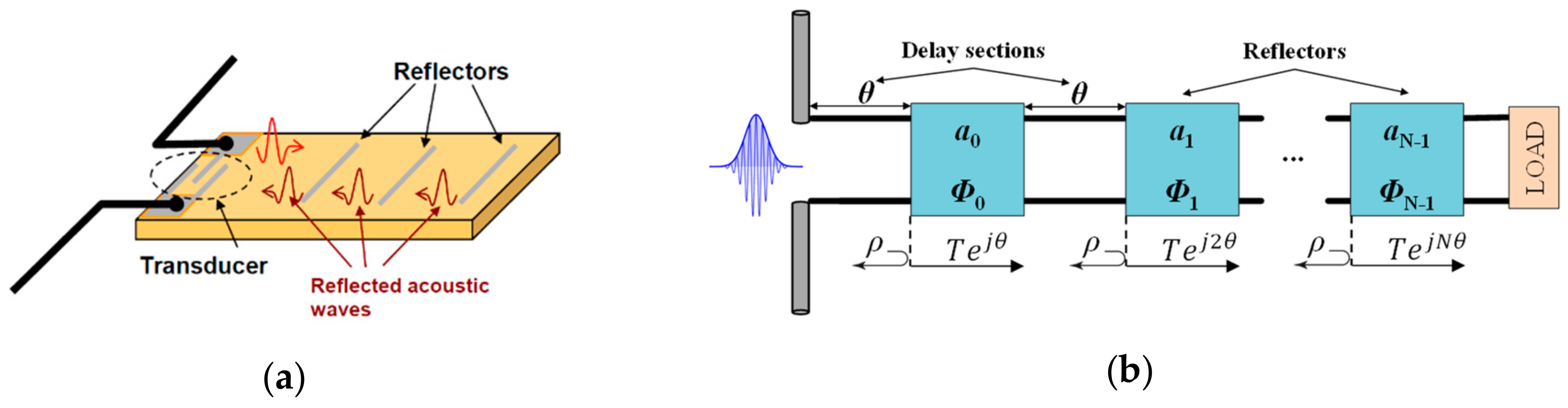
The former chipless-RFID tags were inspired by the operation of RFID tags which encode information in the time domain. Such tags were implemented on surface acoustic wave (SAW) technology [14,15,16,17,18,19] and basically consist of an electro-acoustic transducer connected to an antenna. The working principle is shown in Figure 1a. An electromagnetic pulse is sent by the reader which is received by the antenna and transformed into acoustic energy by the transducer. Then, the acoustic wave propagates through the substrate, reflecting part of it, in those positions where there is a reflector. Such reflections are converted back into electromagnetic energy and transmitted to the reader. This working principle is generally designated as time domain reflectometry (TDR), and the ID code is contained in the echoes generated by the reflectors. It is important to mention that chipless-RFID tags based on SAW technology provide high information capacity (up to 256 bits) [20]. Nevertheless, such tags are not competitive in terms of cost, since tag price may vary around 10–20 euro cents [2].
One solution, with a very similar operating principle (see Figure 1b), consists of implementing chipless-RFID tags composed of a delay line (transmission line), on conventional microwave substrates, which contain discontinuities (as reflectors) or complex impedances at certain positions. Basically, a pulse is sent by the reader which propagates through the delay line. Such a pulse is reflected at those points where there is a discontinuity. In this way, the identification code is constituted by the reflections or echoes produced in the tag. It is important to mention that the speed of sound is 340 m/s, one million times smaller than the speed of light (c). This aspect implies either implementing transmission lines by means of large lengths to produce measurable delays or very narrow pulses in order to avoid overlapping between reflected pulses. Such requirements are difficult to achieve in practice; therefore, the bit encoding capability is generally limited in chipless-RFID tags based on time domain. Nevertheless, the most common codification techniques used in time domain chipless-RFID systems are shown below.
2.1.1. On-Off Keying (OOK)
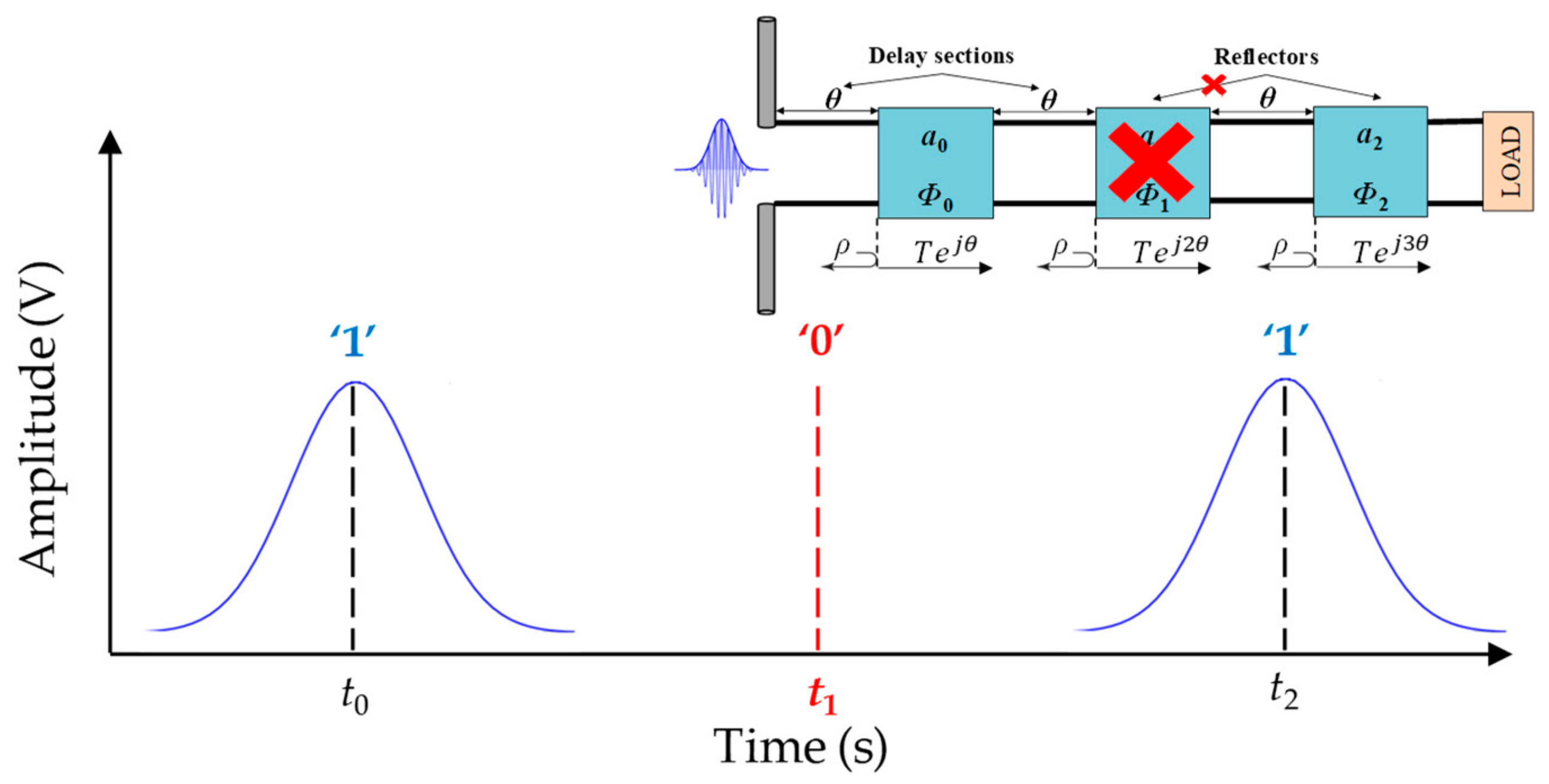
On-off keying (OOK) encoding is considered to be the simplest encoding method in time domain-based chipless-RFID systems. Basically, the logic states ‘0’ and ‘1’ are determined by the absence or presence, respectively, of a reflection of the interrogation signal in a specific time interval, as illustrated in Figure 2.
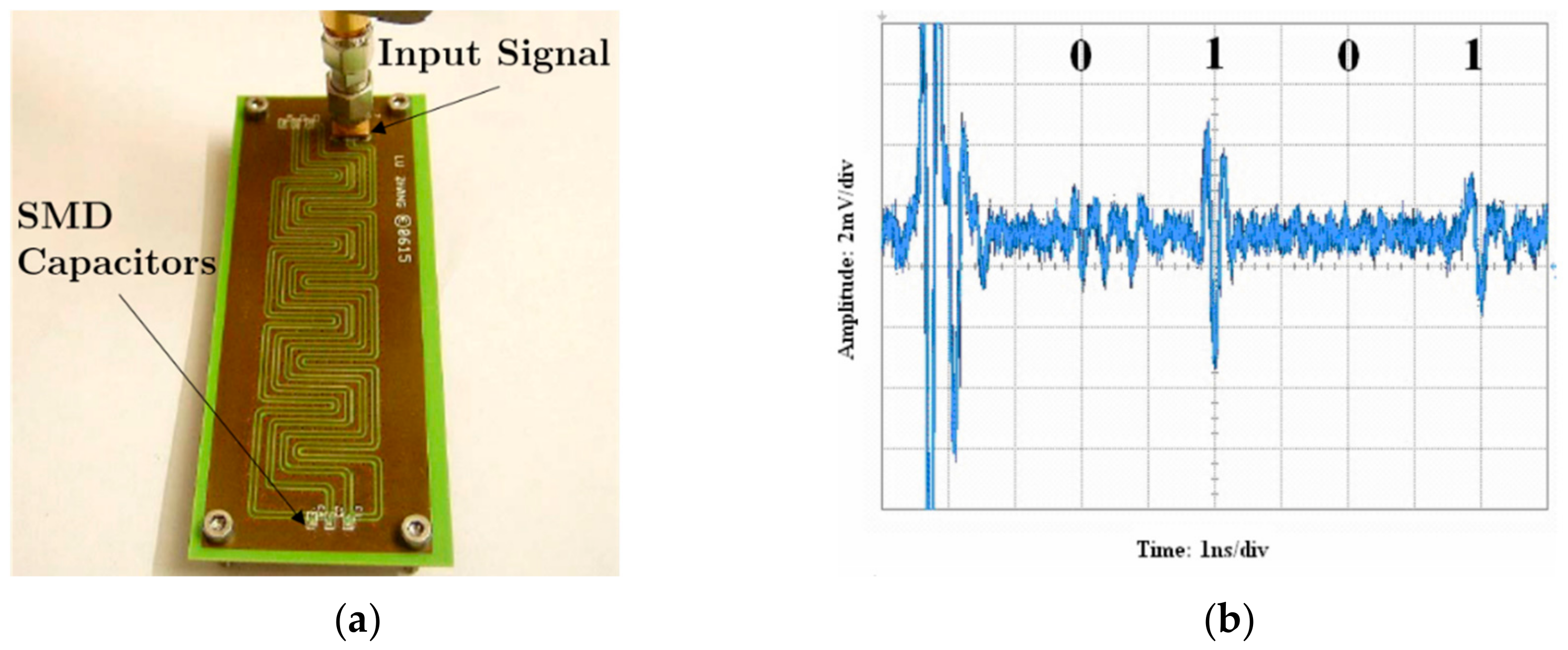
The OOK encoding method was reported for the first time by Zhang et al. [21] in 2006. The tag is composed of a meandered coplanar waveguide transmission line (CPW) with surface mount device (SMD) capacitors inserted in parallel at predefined positions (see Figure 3a). Such capacitors or discontinuities act as reflectors. A pulse of short duration, specifically 2 ns, which propagates through the transmission line CPW, is sent by the reader. The presence of a capacitive discontinuity at certain positions produces a mismatching that results in a reflected pulse which is transmitted back to the reader. The presence of such reflection is interpreted as the logic state ‘1’, whereas its absence is associated to logic state ‘0’. An example of a measured 4-bit tag is shown in Figure 3b.
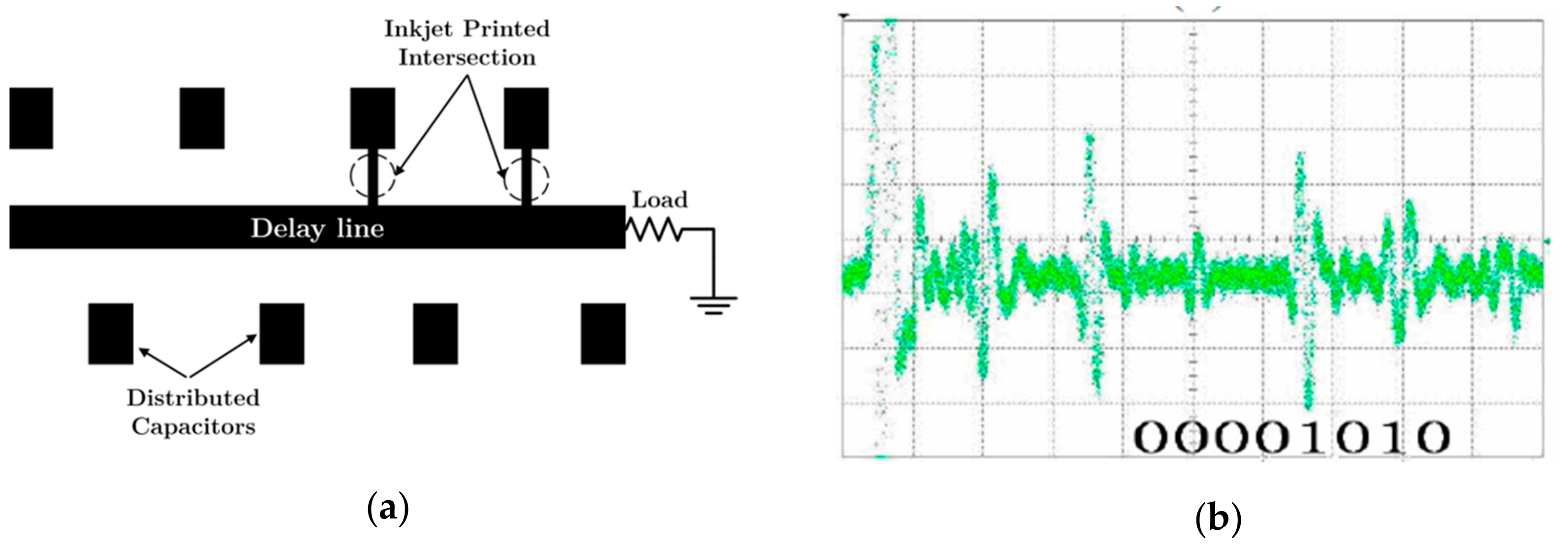
Zheng et al. [22] and Botao et al. [23], in 2008 and 2010, respectively, replaced the SMD capacitors by patches, in order to obtain a fully planar structure. In this case, such patches were printed during tag fabrication and disconnected from the microstrip transmission line, as can be seen in Figure 4a. Consequently, the identification code of the tag is programmed by means of the connection of certain patches to the delay line. In order to reduce the size of the tag by approximately a factor of four, using the same substrate as in [21], the pulse duration of the interrogation signal was reduced to 0.4 ns. An example of a measured 8-bit tag is shown in Figure 4b.
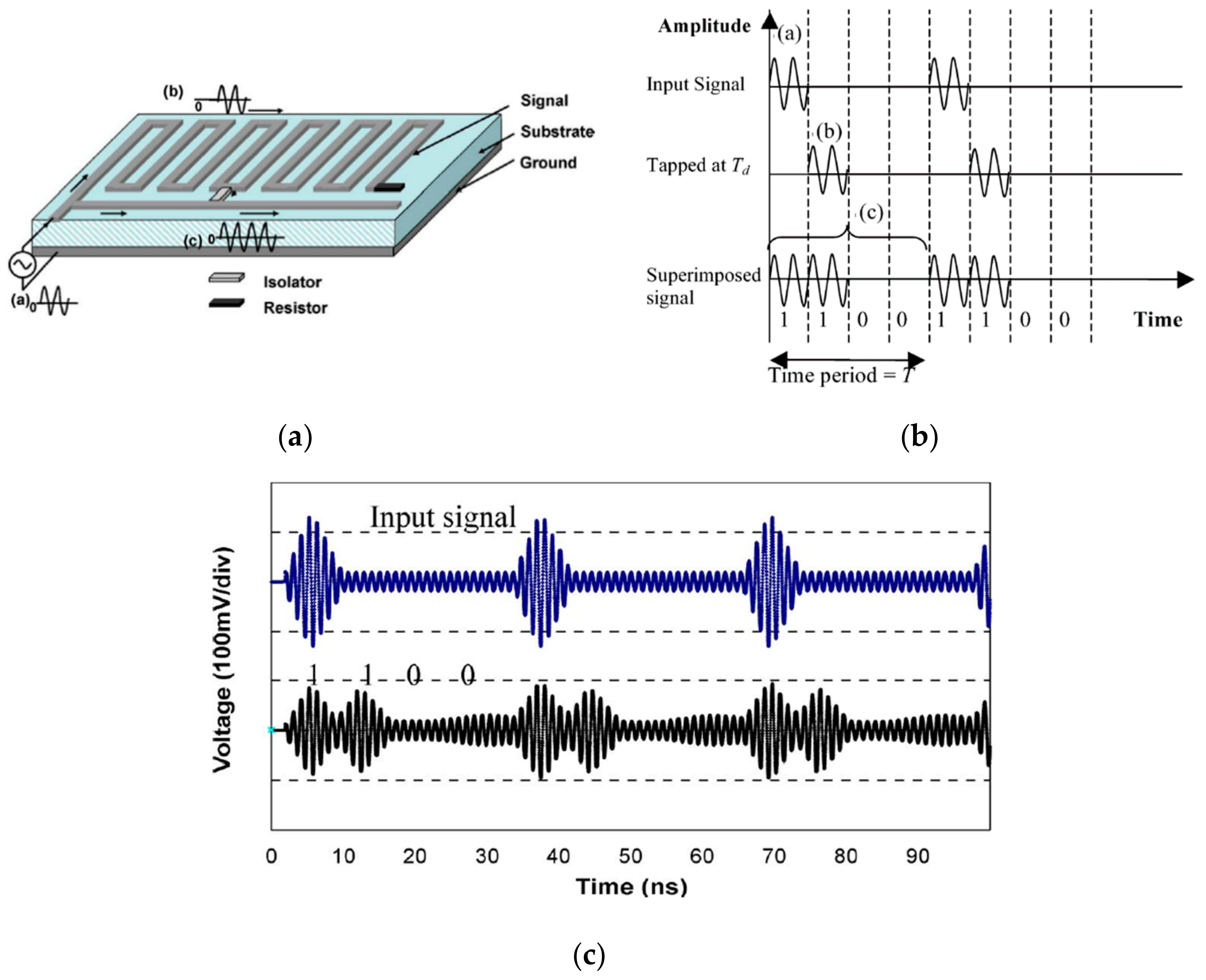
In [24,25] a different strategy to implement chipless-RFID tags based on time domain with OOK coding was reported. The main novelty is the fact that the delay line is used in transmission, rather than in reflection. As shown in Figure 5a, the input signal is divided into two branches, a short and straight line (without delay), and the other one a longer and meandered line (with delay). The two branches are connected by a circulator (which acts as an isolator) to deflect the second pulse at the appropriate time. Thus, the temporal position of the pulse is modified with the position of the isolator, and consequently, the encoding of the tag. In order to clarify the encoding strategy, Figure 5b,c show the principle of code generation, based on the superposition of delayed signals, and a simulated code example, respectively.
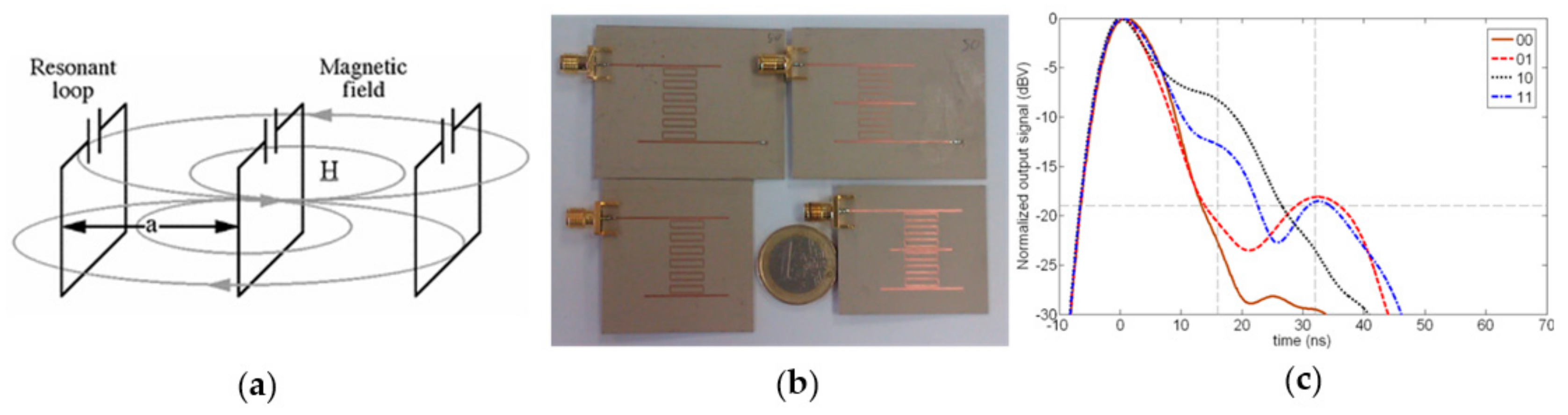
On the other hand, in 2012, a novel strategy based on delay lines able to support magneto-inductive waves (MIW), was proposed by Herraiz et al. [26,27,28]. As depicted in Figure 6a, MIWs are slow waves that propagate through a chain of magnetically coupled resonators [26,29]. Such slow waves exhibit a group velocity (vg) around c/100 (where c is the speed of light in vacuum), hence maximizing the group delay (τg). Thus, for the same delay, shorter delay lines can be achieved (as compared to conventional lines). For the implementation of the delay lines, split ring resonators (SRRs) with rectangular topology were used to maximize the coupling. A microstrip transmission line coupled inductively to the first resonator of the chain of SRRs, acts as a transducer between the microstrip mode and the MIW mode of the delay line. Finally, the additional microstrip transmission lines are used as reflectors, and coupled to specific SRRs of the chain in order to generate a specific identification code. Thereby, the position of the reflectors is different for each tag (see Figure 6b), giving rise to different temporal responses, as appreciated in Figure 6c. The main limitation of this strategy is the fact that the high losses of the MIW delay lines prevent the implementation of tags with high information capacity.
2.1.2. Pulse Position Modulation
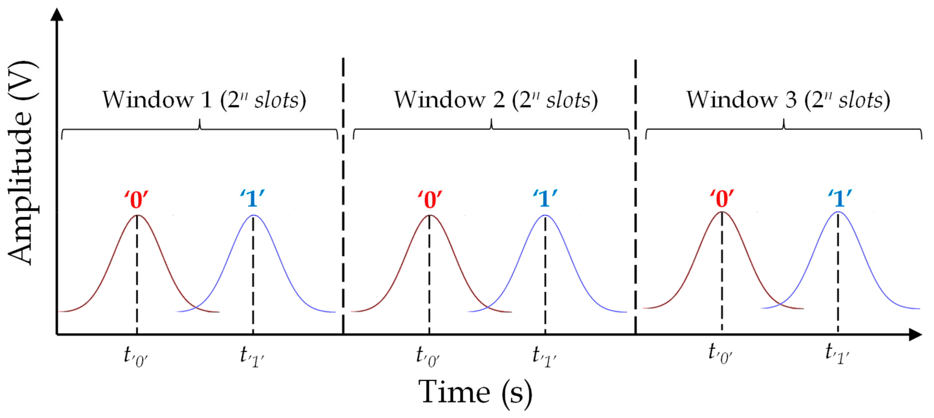
Pulse position modulation (PPM) encoding consists of the variation of the position of a pulse within a certain temporal window. Specifically, PPM encodes n bits with a single pulse, which occupies one of the 2n slots of a temporal window (see Figure 7). The advantage of this encoding, with respect to OOK, is that it requires a smaller number of reflectors. Nevertheless, a longer time span is necessary in order to achieve the same information capacity.
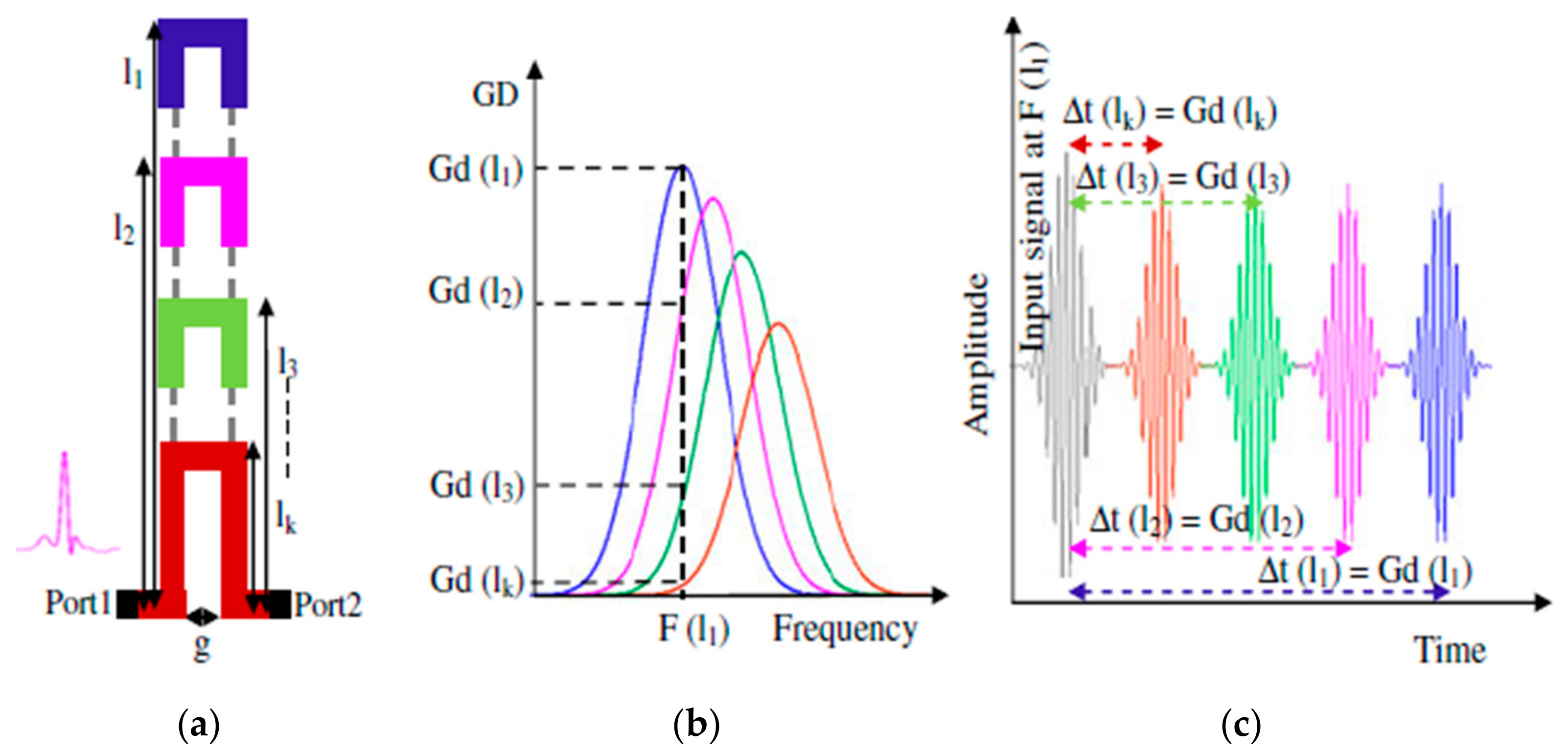
Most of the works reported in the literature that use PPM encoding use dispersive structures which exhibit a frequency-dependent group velocity. Thus, a broadband signal propagating through such structures experiences a different group delay for each spectral component [31,32]. This structure can be implemented by means of C-section all-pass networks [33], which are composed of two coupled lines (see Figure 8a), whose electrical length is λg/4 at the frequency where the group delay is maximum. Therefore, the frequency position of such maximum depends on the length of the structure, as depicted in Figure 8b. Consequently, in the time domain, for the corresponding frequency, a pulse delay equal to the group delay was implemented.
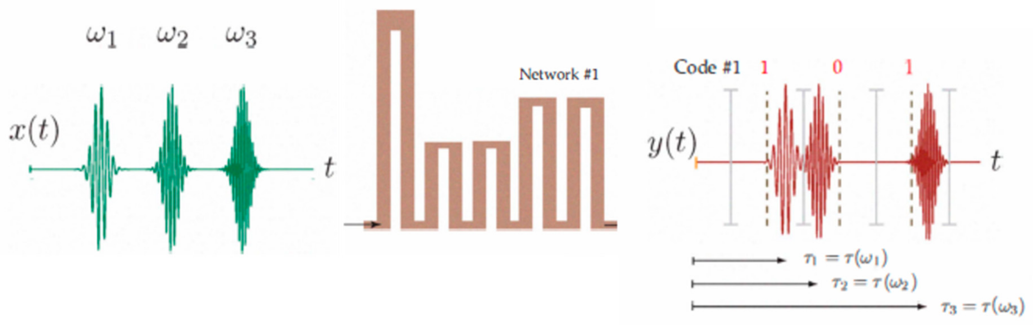
In 2010, a 3-bit tag based on cascaded C-section dispersive structures was implemented for the first time by Gupta et al. [35] (see Figure 9). Such a tag was implemented in order to provide maximums in the group delay at 3, 4, and 5 GHz. In this case, each pulse can provide two different positions within a temporal window, depending on its encoding (‘0’ or ‘1’). Other examples based on this concept can be found in [34,35,36,37].
2.1.3. Phase Modulation
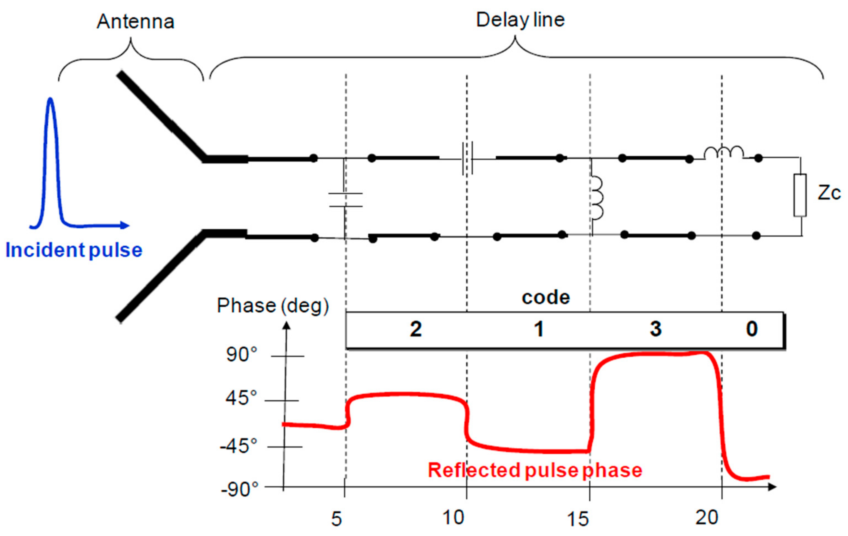
In order to increase the information density of the tag, a different coding method based on the phase modulation of the input pulse to the tag was proposed by Mandel et al. [38,39]. Moreover, such tags include the use of composite right/left handed (CRLH) artificial delay lines, also used in [13,40]. The use of these lines is justified by their lower group velocity, as compared to conventional delay lines. This aspect allows for the implementation of shorter delay lines for a specific delay. In this case, complex loads of different values are used for the purpose of modifying the phase of the reflected pulses, as can be seen in Figure 10. As a result, with four different elements it is possible to achieve four different phase values (2 bits for each reflector). The number of codes that can be generated is, therefore, 4k (where k is the number of reflectors of the delay line).
2.2. Time Division Multiplexing Based Tags
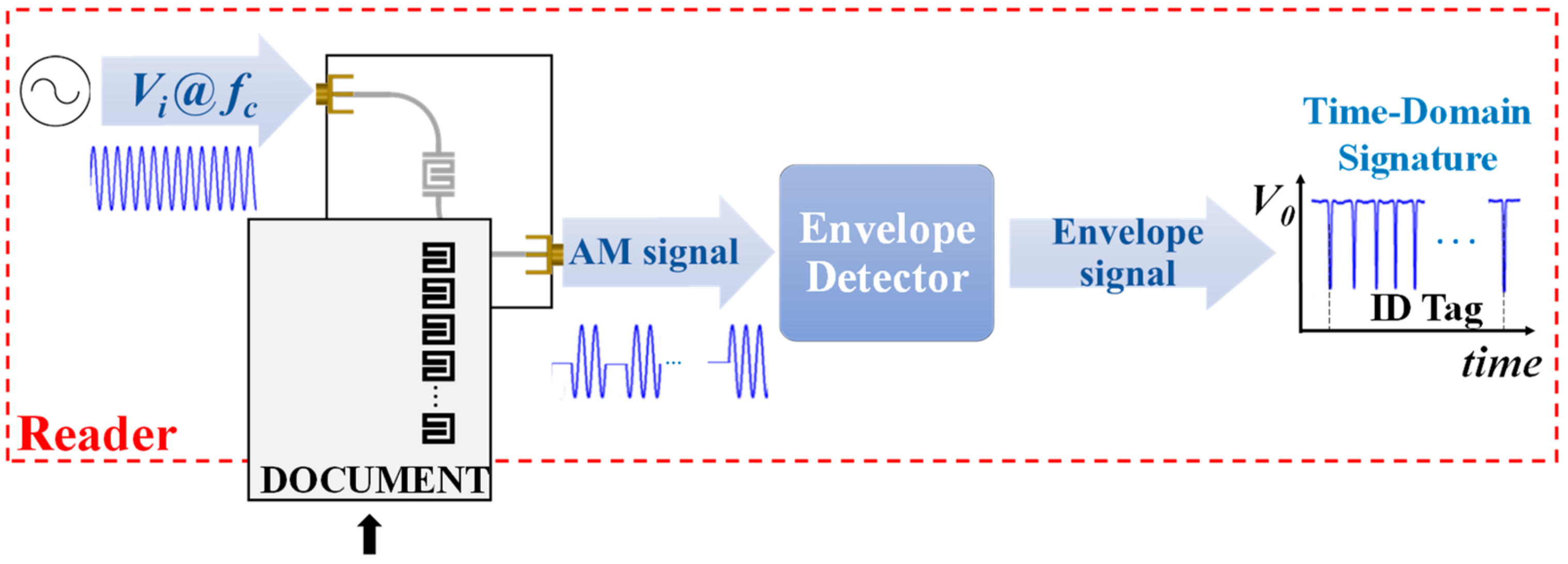
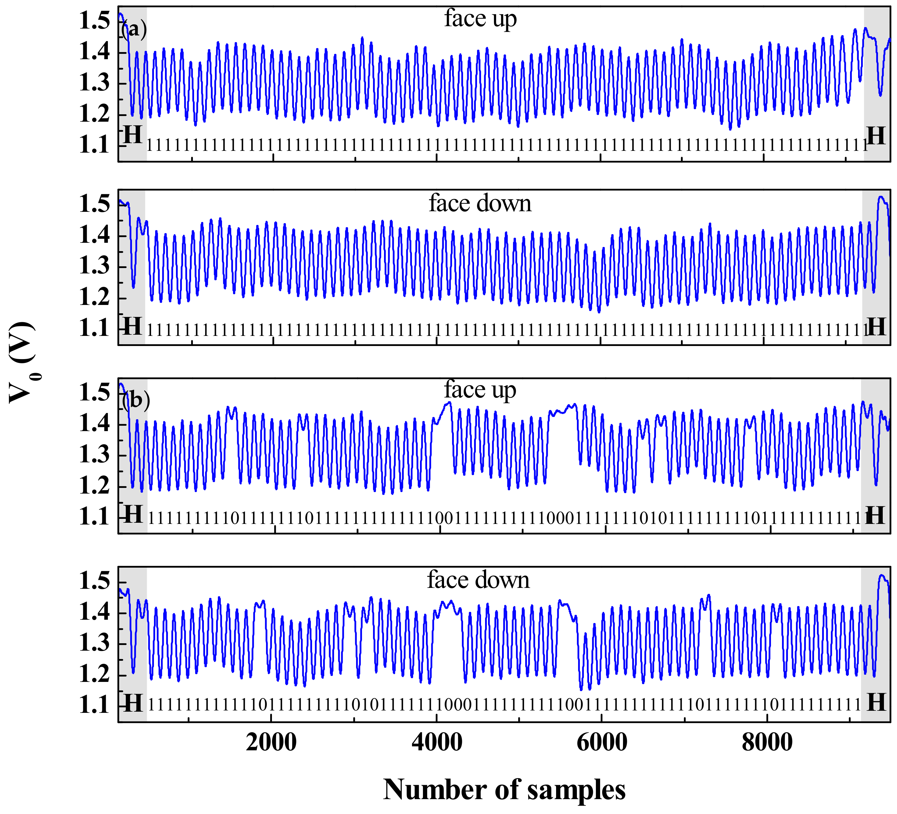
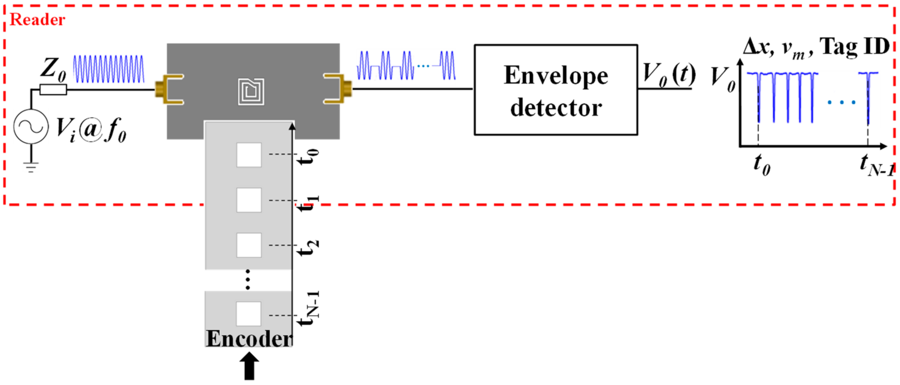
Time division multiplexing is a novel and unconventional strategy to implement chipless-RFID systems based on time domain, which is of particular interest in secure paper applications. Nevertheless, the working principle is completely different than those of the aforementioned chipless-RFID systems. Such a strategy was reported for the first time by Herrojo et al. in 2017 [41]. With this approach, the number of achievable bits is only limited by the area occupied by the tags and the ID code is contained in the amplitude modulated signal generated by the tags. Such tags typically consist of a chain of either resonant elements [42,43,44,45,46,47,48,49] or metallic strips [50,51,52], etched or printed at predefined and equidistant positions on a dielectric substrate. Basically, in a tag reading operation, the tag is mechanically displaced over the sensitive part of the reader. The reader is a planar microwave structure, typically a resonant element, coupled to a transmission line and fed by a harmonic signal. By positioning the resonator of the sensitive part of the reader at a short distance from the tag, the tag motion modulates the amplitude of the feeding signal at the output port of the transmission line (a sketch of the working principle of the proposed chipless-RFID system is depicted in Figure 11). This amplitude modulation is due to the electromagnetic coupling between the resonator of the reader and the resonators or metallic strips of the tag, which modulate the magnitude of the transmission coefficient at the frequency of the feeding signal. With respect to encoding, it can be done either by cutting those elements of the tag associated to the logic state ‘0’ or by its presence/absence at predefined equidistant positions. The former strategy is important in order to reduce costs, since it is possible to fabricate thousands of identical tags with a single mask and programming such tags in a later stage [46]. In [48], such a strategy was demonstrated since the authors implemented an 80-bit tag by means of inkjet printing on a conventional paper (see Figure 12) with all bits set to ‘1’ logic state, and then programmed with different codes by cutting those resonators associated to the logic state ‘0’. Such an approach provides, in terms of performance, high capacity and relatively small size at the expense of near-field tag reading. Nevertheless, the required proximity between the reader and the tag is not an issue in certain applications, such as secure paper (of interest to avoid counterfeiting or copying, e.g., of official documents, etc.).
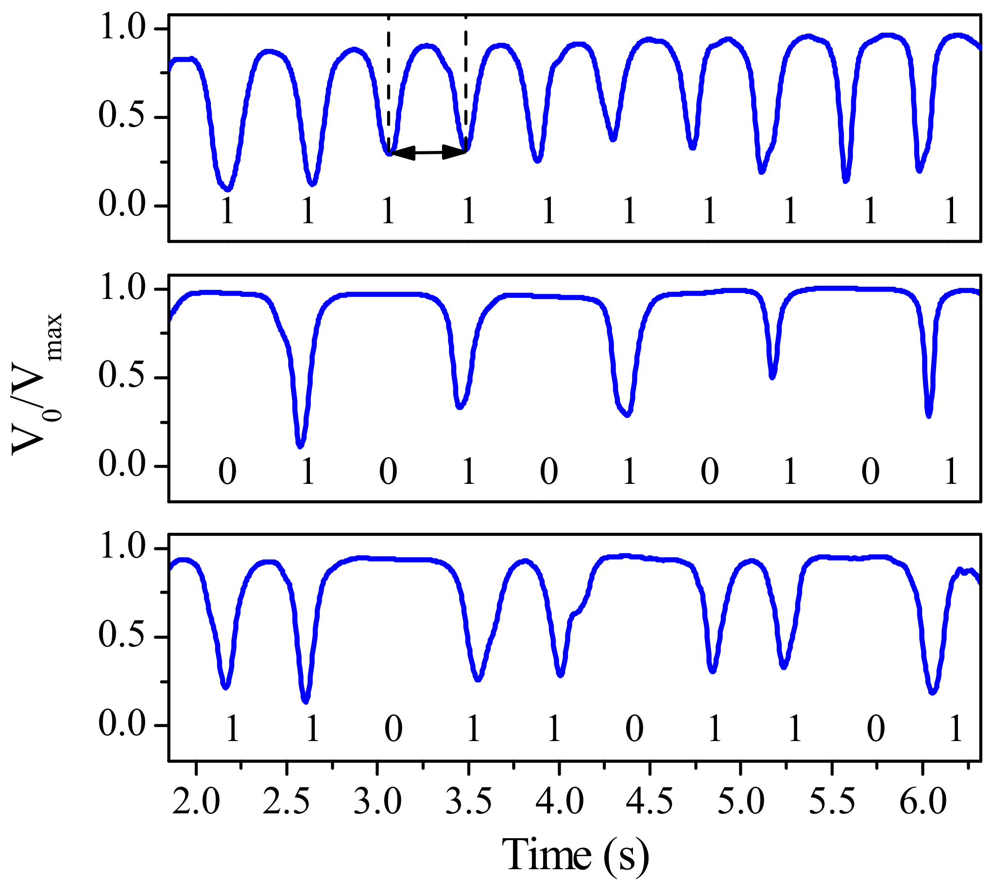
Recently, an alternative approach based on all-dielectric electromagnetic encoders was proposed, avoiding the use of metallic elements (either resonant element or strips). In this case, the AM signal is generated by means of permittivity contrast. Specifically, in [53], the functionality of the system was demonstrated by implementing a chain of 10 apertures on the dielectric substrate RO4003C with permittivity and loss tangent of 3.55 and 0.0021, respectively. The sketch of the working principle is depicted in Figure 13, whereas the normalized measured envelope functions of three different codes are shown in Figure 14.
3. Chipless-RFID Tags Based on Frequency Domain
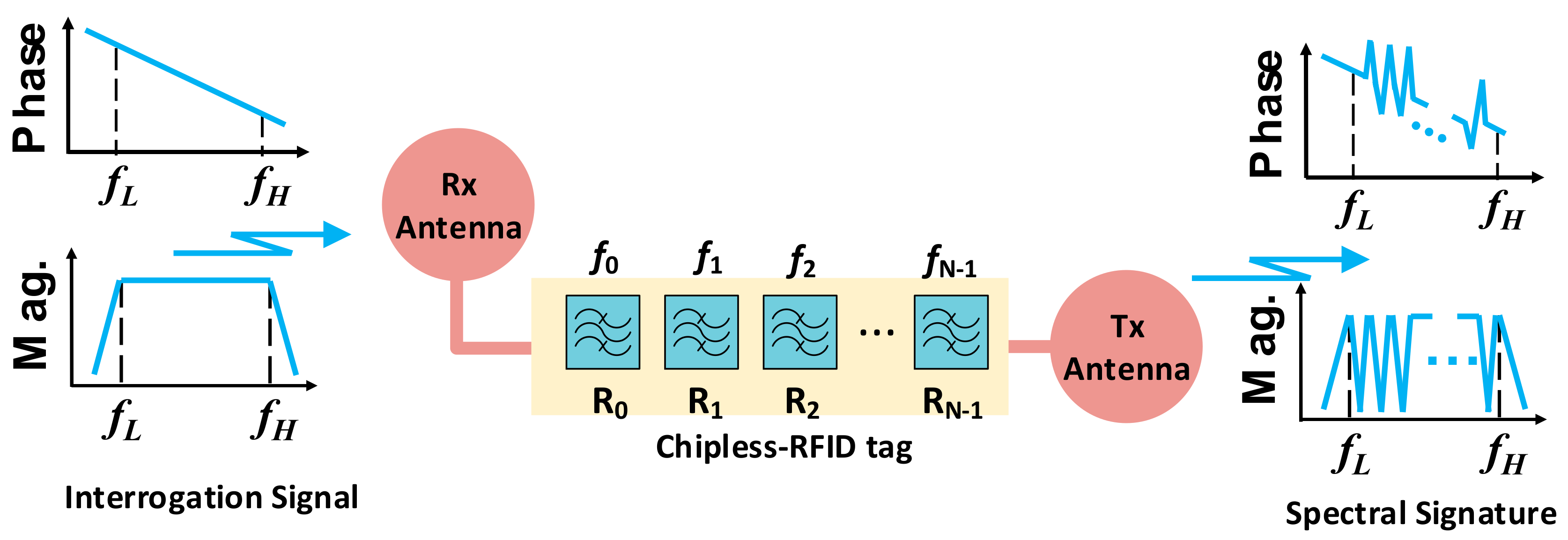
Chipless-RFID tags based on frequency domain, also known as spectral signature barcodes, are implemented with resonant elements tuned at different, and predefined, frequencies. Such frequencies are distributed within a certain frequency band, which must be covered by the interrogation signal. Typically, each resonant element provides a bit of information, and the encoding is determined by the absence or presence of singularities in the amplitude and/or phase of the frequency response of the tag. According to the type of interaction between the interrogation signal and the tag, frequency domain-based tags can be classified as retransmission-based [54,55,56,57,58,59,60,61,62,63,64] and backscattered-based [65,66,67,68,69,70,71,72,73,74,75,76,77,78,79] tags.
3.1. Retransmission-Based Tags
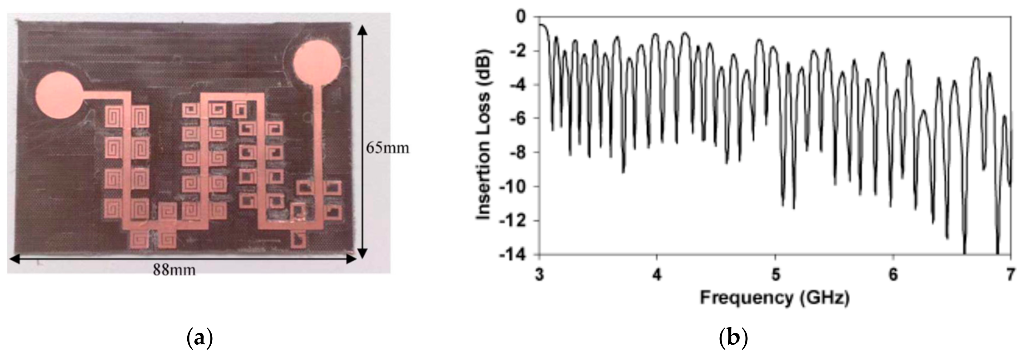
The working principle of retransmission-based tags is depicted in Figure 15. Such tags were designed, implemented, and patented by Preradovic et al. [55] for the first time. Typically, these chipless-RFID tags are equipped with a transmitting and receiving antenna, which are cross- polarized in order to communicate wirelessly with the reader. Such antennas are used for the reception of the interrogation signal and the transmission of the spectral signature of the tag. A tag to be highlighted is the one implemented by Preradovic et al. As shown in Figure 16a, the tag was implemented by a meander microstrip transmission line (to reduce the size) loaded with multiple resonators, specifically 35 spiral resonators, hence encoding 35 bits in a bandwidth and a surface of 4 GHz and 88 × 65 mm2 (including antennas), respectively. With regard to the frequency response of the tag (see Figure 16b), it presents 35 transmission zeros in the magnitude of the spectral signature, introduced by each of the elements which are part of the tag.
3.2. Backscattered-Based Tags
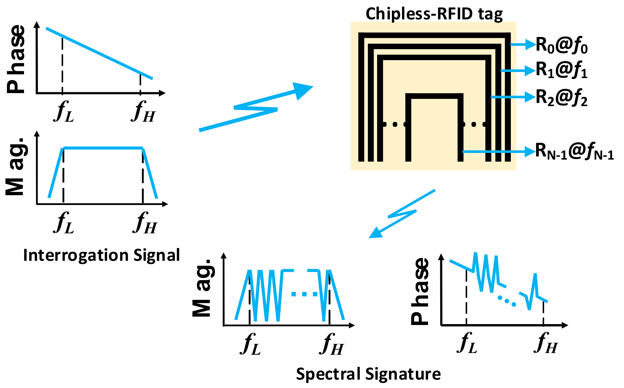
In backscattered chipless-RFID based tags, the resonant elements provide the spectral signature through singularities in the response of the radar cross section (RCS). The main advantage of this strategy is the fact that the use of antennas is not necessary, hence the size of the tag is reduced. The working principle is illustrated in Figure 17.
In 2005, Jalaly et al. [66] proposed a very simple solution consisting of multiple dipoles with a variable capacity implemented on a substrate. The main purpose of this strategy is to create multiple resonances in the bandwidth of the tag. Similar strategy, implemented by the same authors, consists of using dipoles with variable lengths [65], making the structure completely planar. The tags are implemented in the frequency range from 2.4 to 5.8 GHz and the information capacity is 5 bits (the size of the tag is not mentioned by the authors).
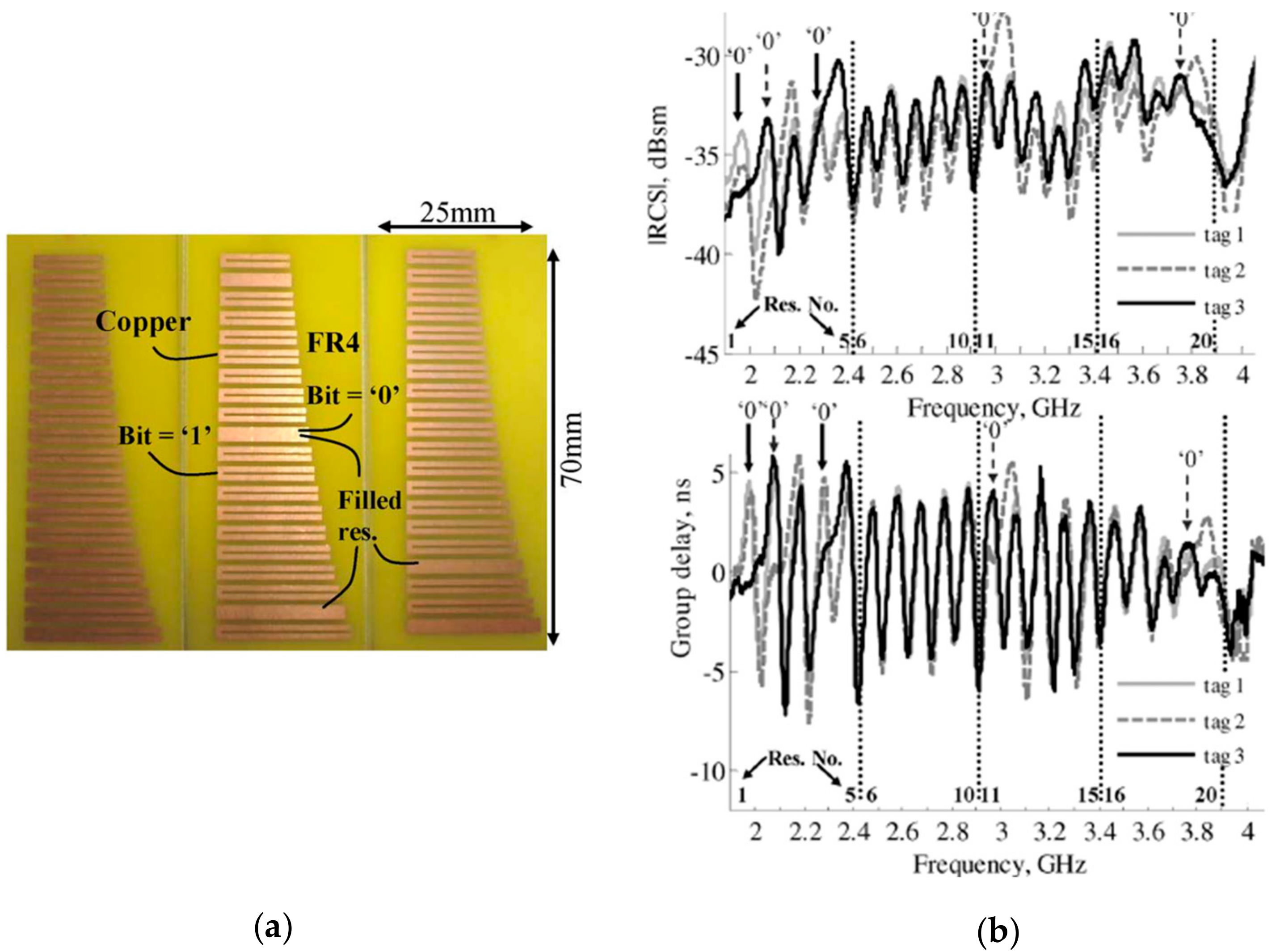
A tag to be highlighted is the one shown in Figure 18a and implemented by Vena et al. [69]. Such a tag is composed of 20 resonant C-shaped elements with resonance frequencies between 2 and 4 GHz, and a size of 25 × 70 mm2. As can be seen in Figure 18b, a peak appears in both the magnitude of the RCS and in the group delay at the resonance frequency of each resonator. With regard to the encoding, the logic state ‘0’ is achieved by shifting the resonance frequency of the resonators (C-shaped resonator) to higher frequencies. Basically, such a frequency shift is achieved by short-circuiting the resonators. The fact that it is not necessary to remove them from the tag is an important aspect, since it opens the possibility of manufacturing all the tags with all the resonators short-circuited, programming them, and removing the short-circuit with a laser, for example.
The main limitation of encoding information in the frequency domain is the bandwidth required to accommodate a large number of bits. Moreover, increasing the information capacity of the tags implies increasing the number of resonant elements, and, consequently, their size. In recent years, in order to minimize such limitations, different research groups have focused their efforts on designing tags able to encode information in more than one domain simultaneously, for example, frequency-phase, frequency-amplitude, etc. Such systems are known as hybrid systems, and the information capacity of the corresponding tags can be substantially increased, as compared to one of the frequency domain tags of this section.
4. Hybrid Tags
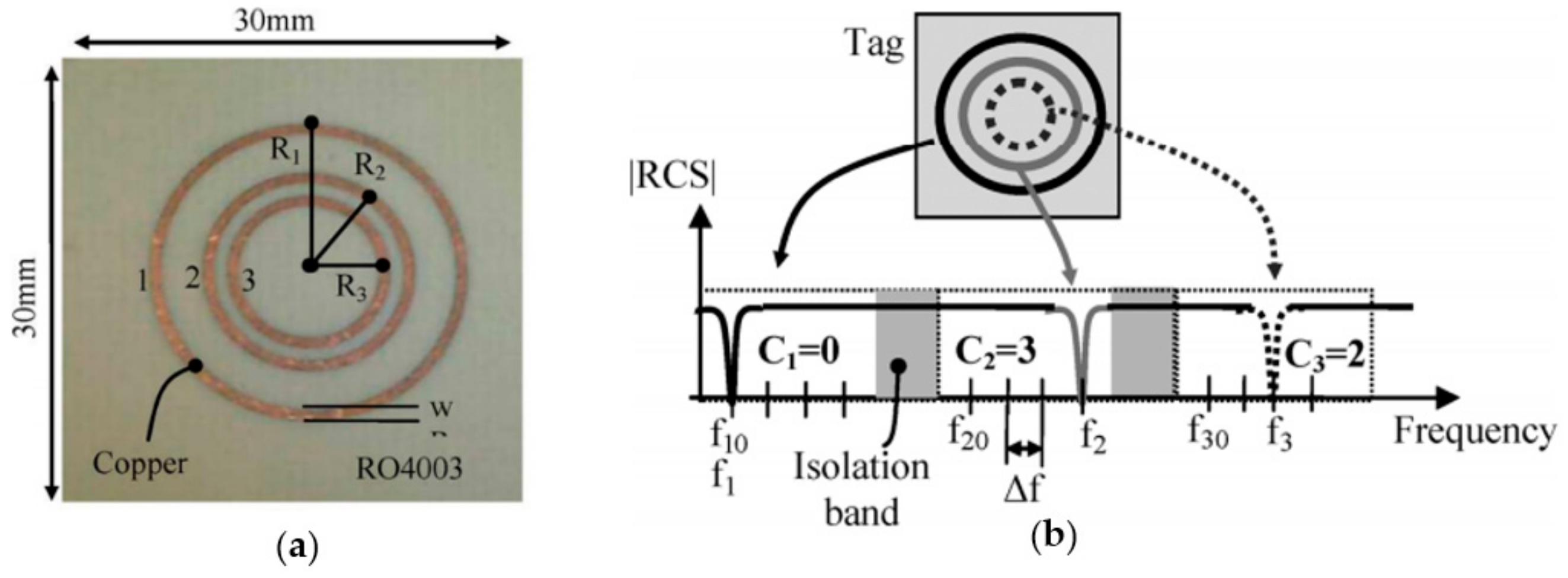
The main objective of hybrid systems is to assign more than two logic states to a single resonant element. In most cases, the approach to achieve such multi-state behavior is by encoding the information in the frequency [80,81,82,83,84]. Thus, the resonance frequency of each resonator can vary between different values within a predefined frequency window. Obviously, with this strategy, the number of states is limited by the bandwidth assigned to each resonant element. To clarify this concept, Figure 19 shows a chipless-RFID tag based on three circular rings. Such a tag operates in the frequency band from 3.1 to 10.6 GHz (i.e., in a bandwidth of 7.5 GHz which has been divided into 30 MHz slots). Therefore, there are 250 slots to be shared between three rings (80 for each one), and, consequently, 803 = 512,000 different codes (19 bits) can be generated in an area of 9 cm2.
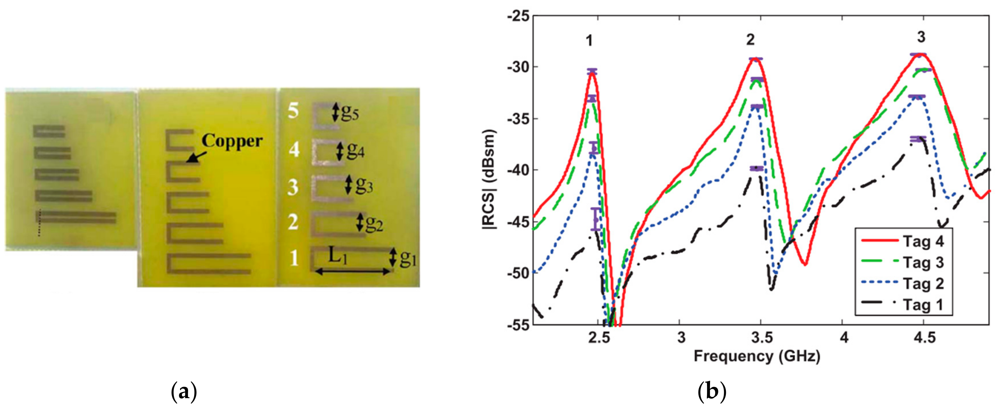
Another approach to achieve a multi-state functionality is to encode the information in the amplitude level of the transmission zeros introduced by the resonant elements of the tags [85,86] or in the level of the magnitude of the resonance peaks of the RCS [87,88,89]. An example of such encoding is shown in Figure 20. The information was encoded in the magnitude level of the resonance peak introduced by the C-shaped resonator. In this case, each resonator provides 2 bits (four states) of information. The bandwidth and the area of the tag are around 3 GHz and 7.2 cm2, respectively.
In 2011, Vena et al. [90] presented a tag which encodes the information in two independent parameters, the phase deviation and the position of the frequency within a given frequency window.
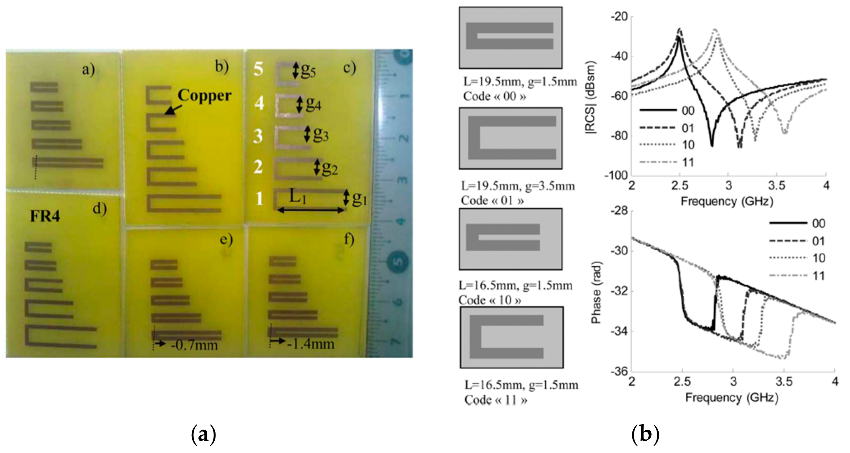
Such a tag is constituted by five C-shaped resonators printed on a FR4 substrate (Figure 21a) with resonance frequencies within the frequency band from 2.5 GHz to 7.5 GHz. Each resonator exhibits a peak and a notch controlled, basically, by the resonator length and g/L ratio, respectively. In the example of Figure 21b, the logic state ‘00’ is assigned to the response with a narrower phase deviation and a peak resonance at 2.5 GHz while the logical state ‘01’ corresponds to the response with a wider phase deviation and maintains the same peak resonance. The logic states ‘10’ and ‘11’ correspond to a narrow and wide phase deviation, respectively, but in this case to the peak resonance at 3 GHz. It is clear that, with this example, 2 bits of information can be assigned to each resonator. However, varying the dimensions of the resonant elements, it is possible to increase the information capacity of each particle. In fact, in the work presented by the authors, each resonator provides 24 states. Therefore, it is possible to generate 245 = 7,962,654 different codes (equivalent to 22.9 bits) in a size of 8 cm2 with only five resonators.
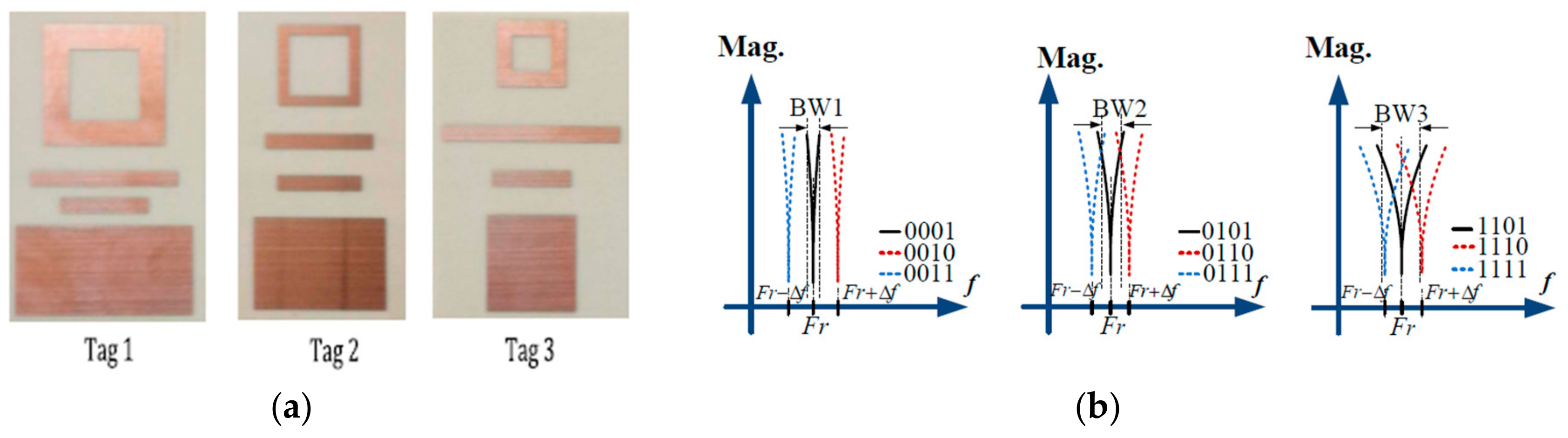
Another possibility, proposed by El-Awamry et al. in [91], consists of a hybrid coding which combines the frequency position of a notch and its bandwidth. This coding technique consists of three different bandwidths (BW1, BW2, and BW3) and three different frequency positions (fr, fr + Δfr, fr − Δf), where fr is the resonant frequency of the resonant particle and Δf is the frequency offset used to encode. In order to achieve three different bandwidths, the tag uses different coding elements: a dipole, a square ring, and a patch (see Figure 22a). Consequently, the control of the position in frequency of the notch is done by varying the dimensions of the resonant elements. With this strategy, 48 bits are achieved (4 bits per resonator) in a size of 20 cm2 and using a bandwidth of 3 GHz.
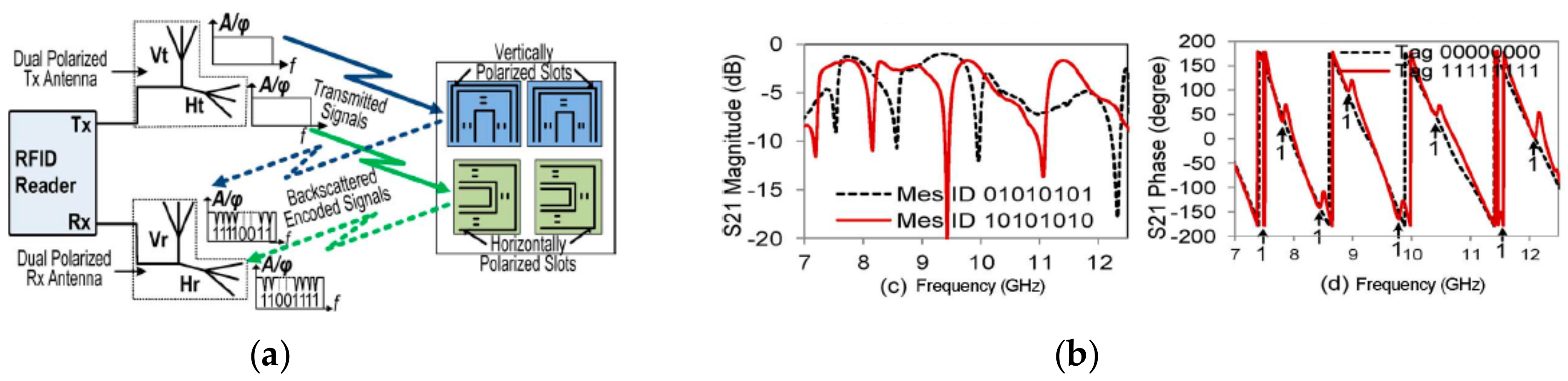
Polarization diversity is also useful to increase the information encoded in a given surface and bandwidth [92,93,94,95]. This method is used in [93] in order to multiply by a factor of two the information capacity of the tags in the same spectral bandwidth. Such tags consist of two sets of rectangular slot resonators etched on rectangular metallic patches with different polarizations (vertical and horizontal), and in turn, each set of resonators is divided in two patches. It is important to mention that the slots etched in each patch are conveniently placed in order to reduce the coupling between resonant elements. On the other hand, in the tag reading operation, the tag must be illuminated with a plane wave orthogonally polarized (Figure 23a). Therefore, the reader consists of two dual-polarized antennas, one to transmit the interrogation signal and the other one to receive the spectral signature of the tag. With this strategy, as a proof-of-concept demonstrator, the authors encoded 16 bits within an area and bandwidth of 3.06 cm2 and 5 GHz, respectively.
5. Comparative Analysis between Coding Techniques
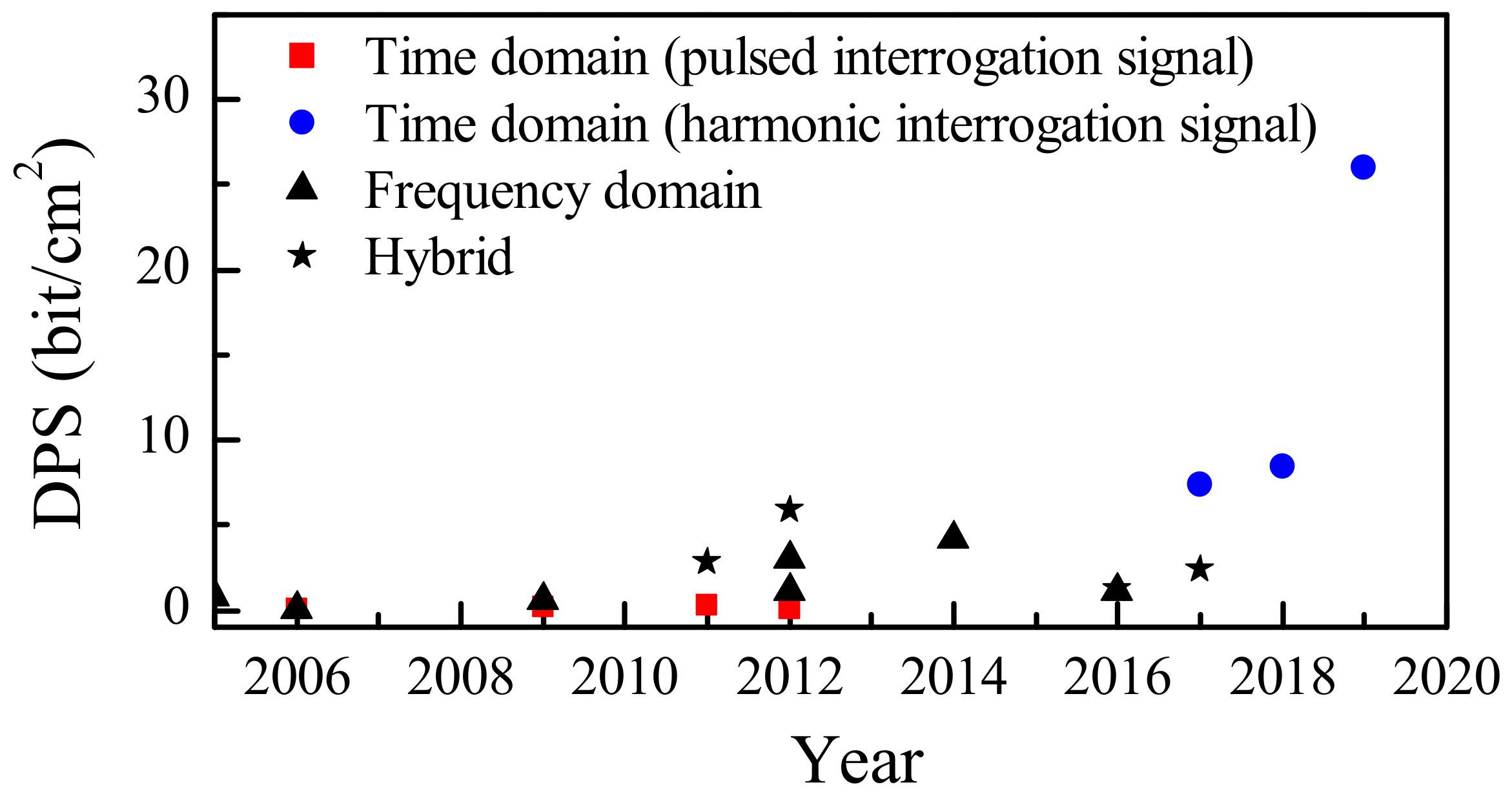
As described in the previous sections, there are different parameters (tag size, bandwidth, number of bits per resonator, etc.), which must be considered in order to determine the efficiency of the coding method used. As mentioned in the introduction, the main challenges in chipless-RFID technology are: (i) to encode the maximum information in the minimum possible area, and in turn, (ii) minimizing the bandwidth. Thus, it is interesting to define figures of merit (or criteria) in order to evaluate and/or compare the different coding methods as well as tag designs. Such figures of merit measure the information density per surface (DPS) in bits/cm2 and density per frequency (DPF) in bits/GHz. Table 1 compares different chipless-RFID tags which can be found in the literature, including those shown and described in this paper. In general, in time domain-based tags where the interrogation signal is a pulsed signal, the DPS is very low due to the fact that it is necessary to implement transmission lines with large lengths in order to produce measurable delays. Conversely, those tags based on time division multiplexing (the interrogation signal is a harmonic signal), present, to the best of our knowledge, the largest DPS. Although this strategy provides a high data density per surface and bandwidth, it is at the expense of sacrificing read range. Nevertheless, this is not an issue in applications such as secure paper (where reading by proximity may be even convenient in order to provide major levels of confidence against eavesdropping or spying). On the other hand, typically, either frequency domain-based tags or hybrid systems need a large number of resonators in order to accommodate a significant number of bits. In fact, both encoding methods provide, in general, tags with similar DPS (either in terms of cm2 or λg2) as can be appreciated either in Figure 24, where the historic evolution of DPS for different encoding methods is shown, or in the Table 1. However, hybrid tags provide larger DPF as compared to frequency domain tags. With regard to the read range (RR), it is difficult to compare both encoding systems (frequency domain and hybrid tags) due to the fact that, in most cases, relevant information, such as transmitted power or antenna gain, among others, are not given in the literature. Indeed, from the results of Table 1, it is difficult to identify a superior encoding system in terms of read range.
Author Contributions
C.H. carried out the state-of-the-art research. C.H. and F.P. carried out some of the experiments shown in the paper as well as the analysis of the data. J.M.-C. contributed with his knowledge in the sensors field. C.H. and F.M. wrote the paper. F.M. was director of the research.
Funding
This work was supported by MINECO-Spain (project TEC2016-75650-R), Generalitat de Catalunya (project 2017SGR-1159), Institució Catalana de Recerca i Estudis Avançats (who awarded Ferran Martín), and FEDER funds.
Conflicts of Interest
The authors declare no conflicts of interest.
References
- Rance, O.; Perret, E.; Siragusa, R.; Lemaître-Auger, P. RCS Synthesis for Chipless RFID: Theory and Design; Elsevier: Atlanta, GA, USA, 2017. [Google Scholar]
- Perret, E. Radio Frequency Identification and Sensors: From RFID to Chipless RFID; John Wiley & Sons, Inc.: Hoboken, NJ, USA, 2014. [Google Scholar]
- Vena, A.; Perret, E.; Tedjini, S. Chipless RFID Based on RF Encoding Particle: Realization, Coding and Reading System; ISTE Press—Elsevier: Atlanta, GA, USA, 2016. [Google Scholar]
- Karmakar, N.C.; Amin, E.M.; Saha, J.K. Chipless RFID Sensors; John Wiley & Sons, Inc.: Hoboken, NJ, USA, 2016. [Google Scholar]
- Karmakar, N.C. (Ed.) Handbook of Smart Antennas for RFID Systems; John Wiley & Sons, Inc.: Hoboken, NJ, USA, 2010. [Google Scholar]
- Rezaiesarlak, R.; Manteghi, M. Chipless RFID: Design Procedure and Detection Techniques; Springer: Berlin/Heidelberg, Germany, 2015. [Google Scholar]
- Finkenzeller, K. RFID Handbook: Fundamentals and Applications in Contactless Smart Cards, Radio Frequency Identification and Near-Field Communication; Wiley-Blackwell: Hoboken, NJ, USA, 2010. [Google Scholar]
- Karmakar, N.C.; Kalansuriya, P.; Azim, R.E.; Koswatta, R. Chipless Radio Frequency Identification Reader Signal Processing; John Wiley & Sons, Inc.: Hoboken, NJ, USA, 2016. [Google Scholar]
- Hunt, V.D.; Puglia, A.; Puglia, M. RFID: A Guide to Radio Frequency Identification; Wiley-Interscience: Hoboken, NJ, USA, 2007. [Google Scholar]
- Karmakar, N.C.; Zomorrodi, M.; Divarathne, C. Advanced Chipless RFID; John Wiley & Sons, Inc.: Hoboken, NJ, USA, 2016. [Google Scholar]
- Preradovic, S.; Karmakar, N. Multiresonator-Based Chipless RFID: Barcode of the Future; Springer: New York, NY, USA, 2012. [Google Scholar]
- Karmakar, N.C.; Amin, E.M.; Saha, J.K. Chipless RFID Reader Architecture; John Wiley & Sons, Inc.: Hoboken, NJ, USA, 2013. [Google Scholar]
- Schussler, M.; Mandel, C.; Maasch, M.; Giere, A.; Jakoby, R. Phase modulation scheme for chipless RFID- and wireless sensor tags. In Proceedings of the 2009 Asia Pacific Microwave Conference, Singapore, 7–10 December 2009; IEEE: Singapore, 2009; pp. 229–232. [Google Scholar]
- Nysen, P.A.; Skeie, H.; Armstrong, D. System for Interrogating a Passive Transponder Carrying Phase-Encoded Information. U.S. Patent No. 4,725,841, 16 February 1988. [Google Scholar]
- Hartmann, C.S. A global SAW ID tag with large data capacity. In Proceedings of the Proceedings 2002 IEEE Ultrasonics Symposium, Munich, Germany, 8–11 October 2002; IEEE: Munich, Germany, 2002; Volume 1, pp. 65–69. [Google Scholar]
- Saldanha, N.; Malocha, D.C. Design parameters for SAW multi-tone frequency coded reflectors. In Proceedings of the IEEE Ultrasonics Symposium, New York, NY, USA, 28–31 October 2007; pp. 2087–2090. [Google Scholar]
- Härmä, S.; Plessky, V.P.; Hartmann, C.S.; Steichen, W. Z-path SAW RFID tag. IEEE Trans. Ultrason. Ferroelectr. Freq. Control 2008, 55, 208–212. [Google Scholar] [CrossRef]
- Han, T.; Wang, W.; Wu, H.; Shui, Y. Reflection and scattering characteristics of reflectors in SAW tags. IEEE Trans. Ultrason. Ferroelectr. Freq. Control 2008, 55, 1387–1390. [Google Scholar] [CrossRef] [PubMed]
- Härmä, S.; Plessky, V.P.; Li, X.; Hartogh, P. Feasibility of ultra-wideband SAW RFID tags meeting FCC rules. IEEE Trans. Ultrason. Ferroelectr. Freq. Control 2009, 56, 812–820. [Google Scholar] [CrossRef] [PubMed]
- Hartmann, C.; Hartmann, P.; Brown, P.; Bellamy, J.; Claiborne, L.; Bonner, W. Anti-collision methods for Global SAW RFID Tag systems. In Proceedings of the IEEE Ultrasonics Symposium, Montreal, QC, Canada, 23–27 August 2004; Volume 2, pp. 805–808. [Google Scholar]
- Zhang, L.; Rodriguez, S.; Tenhunen, H.; Zheng, L.-R. An innovative fully printable RFID technology based on high speed time-domain reflections. In Proceedings of the Conference on High Density Microsystem Design and Packaging and Component Failure Analysis, 2006 (HDP’06), Shanghai, China, 27–28 June 2006; pp. 166–170. [Google Scholar]
- Zheng, L.; Rodriguez, S.; Zhang, L.; Shao, B.; Zheng, L.-R. Design and implementation of a fully reconfigurable chipless RFID tag using Inkjet printing technology. In Proceedings of the 2008 IEEE International Symposium on Circuits and Systems, Seattle, WA, USA, 18–21 May 2008; pp. 1524–1527. [Google Scholar]
- Shao, B.; Chen, Q.; Amin, Y.; Mendoza, D.S.; Liu, R.; Zheng, L.R. An ultra-low-cost RFID tag with 1.67 Gbps data rate by ink-jet printing on paper substrate. In Proceedings of the 2010 IEEE Asian Solid-State Circuits Conference, A-SSCC 2010, Beijing, China, 8–10 November 2010. [Google Scholar]
- Chamarti, A.; Varahramyan, K. Transmission delay line based ID generation circuit for RFID applications. IEEE Microw. Compon. Lett. 2006, 16, 588–590. [Google Scholar] [CrossRef]
- Vemagiri, J.; Chamarti, A.; Agarwal, M.; Varahramyan, K. Transmission line delay-based radio frequency identification (RFID) tag. Microw. Opt. Technol. Lett. 2007, 49, 1900–1904. [Google Scholar] [CrossRef]
- Herraiz-Martínez, F.J.; Paredes, F.; Zamora, G.; Martín, F.; Bonache, J. Printed magnetoinductive-wave (MIW) delay lines for chipless RFID applications. IEEE Trans. Antennas Propag. 2012, 60, 5075–5082. [Google Scholar] [CrossRef]
- Javier, F.; Martínez, H.; Paredes, F.; Zamora, G.; Martín, F. Chipless RFID Tags and Wireless Sensors Based on Planar Magnetoinductive-Wave (MIW) Delay Lines. In Proceedings of the 2012 IEEE International Symposium on Antennas and Propagation, Chicago, IL, USA, 8–14 July 2012. [Google Scholar] [CrossRef]
- Martinez-Martinez, J.J.; Herraiz-Martinez, F.J.; Galindo-Romera, G. A contactless RFID system based on chipless MIW tags. IEEE Trans. Antennas Propag. 2018, 66, 5064–5071. [Google Scholar] [CrossRef]
- Shamonina, E.; Kalinin, V.A.; Ringhofer, K.H.; Solymar, L. Magneto-inductive waveguide. Electron. Lett. 2002, 38, 371. [Google Scholar] [CrossRef]
- Syms, R.R.A.; Floume, T.; Solymar, L.; Young, I.R. Parametric Amplification of Magneto-Inductive Waves. In Nonlinear, Tunable and Active Metamaterials; Shadrivov, I.V., Lapine, M., Kivshar, Y.S., Eds.; Springer International Publishing: Cham, Switzerland, 2015; pp. 35–38. ISBN 978-3-319-08386-5. [Google Scholar]
- Gupta, S.; Nikfal, B.; Caloz, C. RFID system based on pulse-position modulation using group delay engineered microwave C-sections. In Proceedings of the 2010 Asia-Pacific Microwave Conference, Yokohama, Japan, 7–10 December 2010; pp. 203–206. [Google Scholar]
- Nair, R.; Perret, E.; Tedjini, S. Chipless RFID based on group delay encoding. In Proceedings of the 2011 IEEE International Conference on RFID-Technologies and Applications, Sitges, Spain, 15–16 September 2011; Volume 1, pp. 214–218. [Google Scholar]
- Cristal, E.G. Analysis and exact synthesis of cascaded commensurate transmission-line C-Section all-pass networks. IEEE Trans. Microw. Theory Tech. 1966, 14, 285–291. [Google Scholar] [CrossRef]
- Forouzandeh, M.; Karmakar, N.C. Chipless RFID tags and sensors: A review on time-domain techniques. Wirel. Power Transf. 2015, 2, 62–77. [Google Scholar] [CrossRef]
- Gupta, S.; Nikfal, B.; Caloz, C. Chipless RFID system based on group delay engineered dispersive delay structures. IEEE Antennas Wirel. Propag. Lett. 2011, 10, 1366–1368. [Google Scholar] [CrossRef]
- Nair, R.; Perret, E.; Tedjini, S. Temporal multi-frequency encoding technique for chipless RFID applications. In Proceedings of the IEEE MTT-S International Microwave Symposium Digest, Montreal, QC, Canada, 17–22 June 2012; pp. 1–3. [Google Scholar]
- Nair, R.S.; Perret, E.; Tedjini, S. Group delay modulation for pulse position coding based on periodically coupled C-sections. Ann. Telecommun. 2013, 68, 447–457. [Google Scholar] [CrossRef]
- Mandel, C.; Schussler, M.; Maasch, M.; Jakoby, R. A novel passive phase modulator based on LH delay lines for chipless microwave RFID applications. In Proceedings of the 2009 IEEE MTT-S International Microwave Workshop on Wireless Sensing, Local Positioning, and RFID, Cavtat, Croatia, 24–25 September 2009; pp. 1–4. [Google Scholar]
- Jimenez-Saez, A.; Schussler, M.; Nickel, M.; Jakoby, R. Hybrid Time-Frequency Modulation Scheme for Chipless Wireless Identification and Sensing. IEEE Sens. J. 2018, 18, 7850–7859. [Google Scholar] [CrossRef]
- Schüßler, M.; Damm, C.; Maasch, M.; Jakoby, R. Performance evaluation of left-handed delay lines for RFID backscatter applications. In Proceedings of the IEEE MTT-S International Microwave Symposium Digest, Atlanta, GA, USA, 15–20 June 2008; pp. 177–180. [Google Scholar]
- Herrojo, C.; Mata-Contreras, J.; Paredes, F.; Martin, F. Near-field chipless RFID encoders with sequential bit reading and high data capacity. In Proceedings of the IEEE MTT-S International Microwave Symposium Digest, Honololu, HI, USA, 4–9 June 2017. [Google Scholar]
- Herrojo, C.; Mata-Contreras, J.; Paredes, F.; Martín, F. Microwave Encoders for Chipless RFID and Angular Velocity Sensors Based on S-Shaped Split Ring Resonators. IEEE Sens. J. 2017, 17, 4805–4813. [Google Scholar] [CrossRef] [Green Version]
- Herrojo, C.; Mata-Contreras, J.; Nunez, A.; Paredes, F.; Ramon, E.; Martin, F. Near-Field Chipless-RFID System with High Data Capacity for Security and Authentication Applications. IEEE Trans. Microw. Theory Tech. 2017, 65, 5298–5308. [Google Scholar] [CrossRef]
- Herrojo, C.; Mata-Contreras, J.; Paredes, F.; Núñez, A.; Ramon, E.; Martín, F. Near-field chipless-RFID tags with sequential bit reading implemented in plastic substrates. J. Magn. Magn. Mater. 2017, 459, 322–327. [Google Scholar] [CrossRef]
- Herrojo, Cristian; Mata-Contreras, Javier; Paredes, Ferran; Martín, Ferran High data density and capacity in chipless radiofrequency identification (chipless-RFID) tags based on double-chains of S-shaped split ring resonators (S-SRRs). EPJ Appl. Metamat. 2017, 4, 8. [CrossRef]
- Herrojo, C.; Mata-Contreras, J.; Paredes, F.; Nunez, A.; Ramon, E.; Martin, F. Near-Field Chipless-RFID System With Erasable/Programmable 40-bit Tags Inkjet Printed on Paper Substrates. IEEE Microw. Wirel. Components Lett. 2018, 28, 272–274. [Google Scholar] [CrossRef]
- Herrojo, C.; Moras, M.; Paredes, F.; Núñez, A.; Mata-Contreras, J.; Ramon, E.; Martín, F. Time-Domain Signature Chipless- RFID tags. IEEE Microw. Mag. Underprocessing.
- Herrojo, C.; Moras, M.; Paredes, F.; Núñez, A.; Ramon, E.; Mata-Contreras, J.; Martín, F. Very Low-Cost 80-Bit Chipless-RFID Tags Inkjet Printed on Ordinary Paper. Technologies 2018, 6, 52. [Google Scholar] [CrossRef]
- Paredes, F.; Herrojo, C.; Mata-Contreras, J.; Moras, M.; Núñez, A.; Ramon, E.; Martín, F. Near-field chipless radio-frequency identification (RFID) sensing and identification system with switching reading. Sensors 2018, 18, 1148. [Google Scholar] [CrossRef]
- Herrojo, C.; Muela, F.; Mata-Contreras, J.; Paredes, F.; Martin, F. High-Density Microwave Encoders for Motion Control and Near-Field Chipless-RFID. IEEE Sens. J. 2019, 19, 3673–3682. [Google Scholar] [CrossRef]
- Havlicek, J.; Herrojo, C.; Paredes, F.; Mata-Contreras, J.; Martin, F. Enhancing the Per-Unit-Length Data Density in Near-Field Chipless-RFID Systems with Sequential Bit Reading. IEEE Antennas Wirel. Propag. Lett. 2019, 18, 89–92. [Google Scholar] [CrossRef]
- Herrojo, C.; Paredes, F.; Martín, F. Double-Stub Loaded Microstrip Line Reader for Very High Data Density Microwave Encoders. Accepted.
- Herrojo, C.; Vélez, P.; Paredes, F.; Mata-contreras, J.; Martín, F. All-dielectric Electromagnetic Encoders based on Permittivity Contrast for Displacement/Velocity Sensors and Chipless-RFID Tags. In Proceedings of the IEEE MTT-S International Microwave Symposium Digest, Boston, MA, USA, 2–7 June 2019; pp. 2–5. [Google Scholar]
- Preradovic, S.; Balbin, I.; Karmakar, N.C.; Swiegers, G. A novel chipless RFID system based on planar multiresonators for barcode replacement. In Proceedings of the 2008 IEEE International Conference on RFID, Las Vegas, NV, USA, 16–17 April 2008; pp. 289–296. [Google Scholar]
- Preradovic, S.; Karmakar, N. Chipless RFID: Bar code of the future. IEEE Microw. Mag. 2010, 11, 87–97. [Google Scholar] [CrossRef]
- Preradovic, S.; Balbin, I.; Karmakar, N.; Swiegers, G.F. Multiresonator-based chipless RFID system for low-cost item tracking. IEEE Trans. Microw. Theory Tech. 2009, 57, 1411–1419. [Google Scholar] [CrossRef]
- Preradovic, S.; Karmakar, N. Design of chipless RFID tag for operation on flexible laminates. IEEE Antennas Wirel. Propag. Lett. 2010, 9, 207–210. [Google Scholar] [CrossRef]
- Bhuiyan, S.; Azad, A.K.M.; Karmakar, N. Dual-band modified complementary split ring resonator (MCSRR) based multi-resonator circuit for chipless RFID Tag. In Proceedings of the IEEE 8th International Conference on Intelligent Sensors, Sensor Networks, Melbourne, Australia, 2–5 April 2013; pp. 277–281. [Google Scholar]
- Girbau, D.; Lorenzo, J.; Lazaro, A.; Ferrater, C.; Villarino, R. Frequency-coded chipless RFID tag based on dual-band resonators. IEEE Antennas Wirel. Propag. Lett. 2012, 11, 126–128. [Google Scholar] [CrossRef]
- Naqui, J.; Durán-Sindreu, M.; Martín, F. Selective mode suppression in coplanar waveguides using metamaterial resonators. Appl. Phys. A Mater. Sci. Process. 2012, 109, 1053–1058. [Google Scholar] [CrossRef]
- Naqui, J.; Durán-Sindreu, M.; Martin, F. Strategies for the implementation of sensors and RF barcodes based on transmission lines loaded with symmetric resonators. In Proceedings of the 2013 Conference Proceedings: 21st International Conference on Applied Electromagnetics and Communications, Dubrovnik, Croatia, 14–16 October 2013. [Google Scholar]
- Preradovic, S. Chipless RFID System for Barcode Replacement; Monash University: Melbourne, Australia, 2010. [Google Scholar]
- Preradovic, S.; Karmakar, N. Chipless RFID tag with integrated sensor. Proc. IEEE Sensors 2010, 1277–1281. [Google Scholar]
- Preradovic, S.; Karmakar, N. 4th generation multiresonator-based chipless RFID tag utilizing spiral EBGs. In Proceedings of the 2010 European Microwave Conference, Paris, France, 27–28 September 2010; pp. 1746–1749. [Google Scholar]
- Jalaly, I.; Robertson, I.D. RF barcodes using multiple frequency bands. In Proceedings of the IEEE MTT-S International Microwave Symposium Digest, Long Beach, CA, USA, 13–17 June 2005; pp. 139–142. [Google Scholar]
- Jalaly, I.; Robertson, I.D. Capacitively-tuned split microstrip resonators for RFID barcodes. In Proceedings of the 2005 European Microwave Conference, Paris, France, 4–6 October 2005; Volume 2, pp. 1161–1164. [Google Scholar]
- Balbin, I.; Karmakar, N.C. Phase-encoded chipless RFID transponder for large scale low cost applications. IEEE Microw. Compon. Lett. 2009, 19, 509–511. [Google Scholar] [CrossRef]
- Nijas, C.M.; Dinesh, R.; Deepak, U.; Rasheed, A.; Mridula, S.; Vasudevan, K.; Mohanan, P. Chipless RFID tag using multiple microstrip open stub resonators. IEEE Trans. Antennas Propag. 2012, 60, 4429–4432. [Google Scholar] [CrossRef]
- Vena, A.; Perret, E.; Tedjini, S. A fully printable Chipless RFID tag with detuning correction technique. IEEE Microw. Compon. Lett. 2012, 22, 209–211. [Google Scholar] [CrossRef]
- Jang, H.S.; Lim, W.G.; Oh, K.S.; Moon, S.M.; Yu, J.W. Design of low-cost chipless system using printable chipless tag with electromagnetic code. IEEE Microw. Compon. Lett. 2010, 20, 640–642. [Google Scholar] [CrossRef]
- McVay, J.; Hoorfar, A.; Engheta, N. Space-filling curve RFID tags. In Proceedings of the 2006 IEEE Radio and Wireless Symposium, San Diego, CA, USA, 17–19 October 2006; pp. 199–202. [Google Scholar]
- Rezaiesarlak, R.; Manteghi, M. Complex-natural-resonance-based design of chipless RFID tag for high-density data. IEEE Trans. Antennas Propag. 2014, 62, 898–904. [Google Scholar] [CrossRef]
- Nijas, C.M.; Suseela, S.; Deepak, U.; Wahid, P.; Mohanan, P. Low cost chipless tag with multi-bit encoding technique. In Proceedings of the IEEE MTT-S International Microwave and RF Conference, New Delhi, India, 14–16 December 2013; pp. 1–4. [Google Scholar]
- Machac, J.; Polivka, M. Influence of mutual coupling on performance of small scatterers for chipless RFID tags. In Proceedings of the 2014 24th International Conference Radioelektronika, Bratislava, Slovakia, 15–16 April 2014. [Google Scholar]
- Machac, J.; Polivka, M.; Svanda, M.; Havlicek, J. Frequency-domain chipless RFID transponders: Improvement the reading response. In Proceedings of the MIKON 2018—22nd International Microwave and Radar Conference, Poznan, Poland, 14–17 May 2018; pp. 704–707. [Google Scholar]
- Svanda, M.; Machac, J.; Polivka, M.; Havlicek, J. A comparison of two ways to reducing the mutual coupling of chipless RFID tag scatterers. In Proceedings of the 2016 21st International Conference on Microwave, Radar and Wireless Communications, MIKON 2016, Krakow, Poland, 9–11 May 2016; pp. 2–5. [Google Scholar]
- Svanda, M.; Havlicek, J.; Machac, J.; Polivka, M. Polarisation independent chipless RFID tag based on circular arrangement of dual-spiral capacitively-loaded dipoles with robust RCS response. IET Microw. Antennas Propag. 2018, 12, 2167–2171. [Google Scholar] [CrossRef]
- Polivka, M.; Svanda, M.; Havlicek, J.; Machac, J. Semi-Platform Tolerant 20-bit Chipless RFID Tag Composed of Dipole Array Closely Coupled to Plate. In Proceedings of the 12th European Conference on Antennas and Propagation (EuCAP 2018), London, UK, 9–13 April 2018; p. 123. [Google Scholar]
- Wang, L.; Liu, T.; Siden, J.; Wang, G. Design of Chipless RFID Tag by Using Miniaturized Open-Loop Resonators. IEEE Trans. Antennas Propag. 2018, 66, 618–626. [Google Scholar] [CrossRef]
- Vena, A.; Perret, E.; Tedjini, S. High-capacity chipless RFID tag insensitive to the polarization. IEEE Trans. Antennas Propag. 2012, 60, 4509–4515. [Google Scholar] [CrossRef]
- Vena, A.; Perret, E.; Tedjini, S. Design of compact and auto-compensated single-layer chipless RFID tag. IEEE Trans. Microw. Theory Tech. 2012, 60, 2913–2924. [Google Scholar] [CrossRef]
- Khaliel, M.; El-Awamry, A.; Fawky, A.; El-Hadidy, M.; Kaiser, T. A novel co/cross-polarizing chipless RFID tags for high coding capacity and robust detection. In Proceedings of the 2015 IEEE International Symposium on Antennas and Propagation & USNC/URSI National Radio Science Meeting, Vancouver, BC, Canada, 19–24 July 2015; pp. 159–160. [Google Scholar]
- Chen, Y.S.; Jiang, T.Y.; Lai, F.P. Automatic Topology Generation of 21 Bit Chipless Radio Frequency Identification Tags Using a Noniterative Technique. IEEE Antennas Wirel. Propag. Lett. 2019, 18, 293–297. [Google Scholar] [CrossRef]
- Chen, Y.-S.; Jiang, T.-Y.; Lai, F.-P. Design rule development for frequency-coded chipless radiofrequency identification with high capacity. IET Microw. Antennas Propag. 2019, 1255–1261. [Google Scholar] [CrossRef]
- Ni, Y.; Huang, X.; Lv, Y.; Cheng, C. Hybrid coding chipless tag based on impedance loading. IET Microw. Antennas Propag. 2017, 11, 1325–1331. [Google Scholar] [CrossRef]
- Herrojo, C.; Paredes, F.; Mata-Contreras, J.; Zuffanelli, S.; Martin, F. Multistate Multiresonator Spectral Signature Barcodes Implemented by Means of S-Shaped Split Ring Resonators (S-SRRs). IEEE Trans. Microw. Theory Tech. 2017, 65. [Google Scholar] [CrossRef]
- Rance, O.; Siragusa, R.; Lemaitre-Auger, P.; Perret, E. RCS magnitude coding for chipless RFID based on depolarizing tag. In Proceedings of the 2015 IEEE MTT-S International Microwave Symposium, Phoenix, AZ, USA, 17–22 May 2015; pp. 2–5. [Google Scholar]
- Vena, A.; Babar, A.A.; Sydanheimo, L.; Tentzeris, M.M.; Ukkonen, L. A novel near-transparent ask-reconfigurable inkjet-printed chipless RFID tag. IEEE Antennas Wirel. Propag. Lett. 2013, 12, 753–756. [Google Scholar] [CrossRef]
- Rance, O.; Siragusa, R.; Lemaitre-Auger, P.; Perret, E. Toward RCS magnitude level coding for chipless RFID. IEEE Trans. Microw. Theory Tech. 2016, 64, 2315–2325. [Google Scholar] [CrossRef]
- Vena, A.; Perret, E.; Tedjini, S. Chipless RFID tag using hybrid coding technique. IEEE Trans. Microw. Theory Tech. 2011, 59, 3356–3364. [Google Scholar] [CrossRef]
- El-Awamry, A.; Khaliel, M.; Fawky, A.; El-Hadidy, M.; Kaiser, T. Novel notch modulation algorithm for enhancing the chipless RFID tags coding capacity. In Proceedings of the 2015 IEEE International Conference on RFID, San Diego, CA, USA, 15–17 April 2015; pp. 25–31. [Google Scholar]
- Islam, M.A.; Karmakar, N.C. Compact printable chipless RFID systems. IEEE Trans. Microw. Theory Tech. 2015, 63, 3785–3793. [Google Scholar] [CrossRef]
- Islam, M.A.; Karmakar, N. A novel compact printable dual-polarized chipless RFID system. IEEE Trans. Microw. Theory Tech. 2012, 60, 2142–2151. [Google Scholar] [CrossRef]
- Vena, A.; Perret, E.; Tedjini, S. A compact chipless RFID tag using polarization diversity for encoding and sensing. In Proceedings of the 2012 IEEE International Conference on RFID, RFID 2012, Orlando, FL, USA, 3–5 April 2012; pp. 191–197. [Google Scholar]
- Babaeian, F.; Karmakar, N.C. Hybrid chipless RFID Tags- A pathway to EPC global standard. IEEE Access 2018, 6, 67415–67426. [Google Scholar] [CrossRef]
Figure 1.
Working principle of a chipless radiofrequency identification (RFID) system based on (a) surface acoustic wave (SAW) technology and (b) delay lines. In both cases, the functionality is known as time domain reflectometry (TDR).
Figure 1.
Working principle of a chipless radiofrequency identification (RFID) system based on (a) surface acoustic wave (SAW) technology and (b) delay lines. In both cases, the functionality is known as time domain reflectometry (TDR).

Figure 2.
Working principle of on-off keying encoding.

Figure 3.
(a) Photograph of the chipless-RFID tag proposed by Zhang et al. (code ‘0101’); (b) measured code ‘0101’. Figure extracted from [21].
Figure 3.
(a) Photograph of the chipless-RFID tag proposed by Zhang et al. (code ‘0101’); (b) measured code ‘0101’. Figure extracted from [21].

Figure 4.
(a) Layout of the chipless-RFID tag proposed by Zheng et al. programmed with the code ‘00001010’ and (b) measurement of the code ‘00001010’. Figure extracted from [22].
Figure 4.
(a) Layout of the chipless-RFID tag proposed by Zheng et al. programmed with the code ‘00001010’ and (b) measurement of the code ‘00001010’. Figure extracted from [22].

Figure 5.
(a) Sketch of the delay line proposed by Chamarti et al.; (b) binary code generation by the superposition of delayed lines; (c) simulated input and output signals. Figure extracted from [24].
Figure 5.
(a) Sketch of the delay line proposed by Chamarti et al.; (b) binary code generation by the superposition of delayed lines; (c) simulated input and output signals. Figure extracted from [24].

Figure 6.
(a) Magneto inductive waveguide which consists of a set of capacitively loaded loops, magnetically coupled to each other. Figure extracted from [30]; (b) photograph of the fabricated set of 2-bit chipless RFID tags proposed by Herraiz et al. and (c) measured response. Figure extracted from [26].

Figure 7.
Working principle of pulse position modulation encoding.

Figure 8.
Principle of encoding by means of group delay: (a) structure of the chipless-RFID tag; (b) group delay vs. frequency for different lengths of C-sections, and (c) the corresponding time domain response. Figure extracted from [34].
Figure 8.
Principle of encoding by means of group delay: (a) structure of the chipless-RFID tag; (b) group delay vs. frequency for different lengths of C-sections, and (c) the corresponding time domain response. Figure extracted from [34].

Figure 9.
Chipless-RFID tag proposed by Gupta et al. fed with three Gaussian pulses with frequency ω1, ω2, and ω3 and an example of PPM encoding. Figure extracted from [35].
Figure 9.
Chipless-RFID tag proposed by Gupta et al. fed with three Gaussian pulses with frequency ω1, ω2, and ω3 and an example of PPM encoding. Figure extracted from [35].

Figure 10.
Temporal encoding based on the phase modulation of the input pulse to the tag. Figure extracted from [3].
Figure 10.
Temporal encoding based on the phase modulation of the input pulse to the tag. Figure extracted from [3].

Figure 11.
Sketch of the working principle of time domain chipless-RFID systems based on near-field coupling and sequential bit reading.
Figure 11.
Sketch of the working principle of time domain chipless-RFID systems based on near-field coupling and sequential bit reading.

Figure 12.
(a) Measured envelope of the inkjet-printed 80-bit tag with all bits set to the logic state ‘1’ and (b) 80-bit programmed tag with the indicated code. Figure extracted from [48].
Figure 12.
(a) Measured envelope of the inkjet-printed 80-bit tag with all bits set to the logic state ‘1’ and (b) 80-bit programmed tag with the indicated code. Figure extracted from [48].

Figure 13.
Sketch of the working principle of the all-dielectric electromagnetic encoders based on permittivity contrast. Figure extracted from [53].
Figure 13.
Sketch of the working principle of the all-dielectric electromagnetic encoders based on permittivity contrast. Figure extracted from [53].

Figure 14.
Normalized measured envelope functions of the indicated codes. Figure extracted from [53].
Figure 14.
Normalized measured envelope functions of the indicated codes. Figure extracted from [53].

Figure 15.
The working principle of retransmission frequency domain chipless-RFID systems.

Figure 16.
(a) Photograph and (b) measured response of a 35-bit tag implemented by Preradovic et al. Figure extracted from [56].
Figure 16.
(a) Photograph and (b) measured response of a 35-bit tag implemented by Preradovic et al. Figure extracted from [56].

Figure 17.
The working principle of backscattered frequency domain chipless-RFID systems.

Figure 18.
(a) Photograph and (b) measured radar cross section (RCS), and group delay of three different 20-bit tags implemented by Vena et al. Figure extracted from [69].
Figure 18.
(a) Photograph and (b) measured radar cross section (RCS), and group delay of three different 20-bit tags implemented by Vena et al. Figure extracted from [69].

Figure 19.
(a) Photograph of a chipless-RFID tag constituted by three circular rings and (b) the coding principle. Figure extracted from [80].
Figure 19.
(a) Photograph of a chipless-RFID tag constituted by three circular rings and (b) the coding principle. Figure extracted from [80].

Figure 20.
(a) Photograph of three chipless-RFID tags proposed by Vena et al. and (b) the measured frequency response. Figure extracted from [89].
Figure 20.
(a) Photograph of three chipless-RFID tags proposed by Vena et al. and (b) the measured frequency response. Figure extracted from [89].

Figure 21.
(a) Photograph of six chipless-RFID tags proposed by Vena et al. and (b) the measured frequency response. Figure extracted from [90].
Figure 21.
(a) Photograph of six chipless-RFID tags proposed by Vena et al. and (b) the measured frequency response. Figure extracted from [90].

Figure 22.
(a) Photograph of three chipless-RFID tags proposed by El-Awamry et al. and (b) the working principle of the proposed encoding. Figure extracted from [91].
Figure 22.
(a) Photograph of three chipless-RFID tags proposed by El-Awamry et al. and (b) the working principle of the proposed encoding. Figure extracted from [91].

Figure 23.
(a) Chipless-RFID based on polarization diversity proposed by Islam et al. and (b) measured frequency response of a tag with the indicated code. Figure extracted from [93].
Figure 23.
(a) Chipless-RFID based on polarization diversity proposed by Islam et al. and (b) measured frequency response of a tag with the indicated code. Figure extracted from [93].

Figure 24.
Historic evolution of DPS for different encoding methods.


Table 1.
Comparative analysis between encoding techniques.
| Ref./Year | BW (GHz) | Bits | Area (cm2) | DPF (bit/GHz) | DPS (bit/cm2) | DPS (bits/λg2) | RR (cm) |
|---|---|---|---|---|---|---|---|
| Time Domain (Pulsed Interrogation Signal) | |||||||
| [21]/2006 | --- | 4 | --- | --- | --- | --- | --- |
| [22]/2008 | --- | 8 | --- | --- | --- | --- | --- |
| [24]/2006 | --- | 4 | 59.4 | --- | 0.07 | --- | --- |
| [26]/2012 | 0.05 ** | 2 | --- | 40 | --- | --- | --- |
| [32]/2011 | --- | 2 | 8.75 | --- | 0.23 | --- | --- |
| [36]/2012 | --- | 2 | 70.0 | --- | 0.03 | --- | --- |
| [38]/2009 | 0.8 ** | 5 | 26 | 6.25 | 0.19 | --- | --- |
| Time Domain (Harmonic Interrogation Signal) | |||||||
| [48]/2018 | * | 80 | 9.44 | * | 8.47 | 153.3 | 0.025 |
| [42]/2017 | * | 40 | 5.40 | * | 7.40 | 117.3 | 0.05 |
| [52]/2019 | * | 100 | 3.84 | * | 26.04 | 412.6 | 0.05 |
| Frequency Domain | |||||||
| [56]/2009 | 3.1–10.6 | 35 | 57.2 | 8.97 | 0.61 | 4.790 | 5 |
| [65]/2005 | 5–6 | 5 | 6.48 | 11.1 | 0.77 | 10.43 | 150 |
| [76]/2016 | 1.9–3.1 | 20 | 17.5 | 16.7 | 1.14 | 48.69 | 20 |
| [69]/2012 | 2–4 | 20 | 17.5 | 10.0 | 1.14 | 24.84 | 50 |
| [71]/2006 | 0.7–0.9 | 5 | 50.1 | 25.0 | 0.10 | 60.23 | 30 |
| [72]/2014 | 3.1–10.6 | 24 | 5.76 | 3.20 | 4.17 | 36.33 | 60 |
| [81]/2012 | 2–5.5 | 9 | 3.00 | 2.57 | 3.00 | 41.74 | 65 |
| Hybrid | |||||||
| [89]/2016 | 2–5 | 9 | 7.20 | 3.00 | 1.25 | 18.01 | 60 |
| [86]/2017 | 2–3 | 16 | 6.75 | 16.0 | 2.37 | 96.15 | *** |
| [90]/2011 | 2.5–7.5 | 22.9 | 8.00 | 4.58 | 2.86 | 22.40 | 45 |
| [93]/2012 | 3.2–9.6 | 64 | 10.9 | 10.0 | 5.88 | 52.66 | 5 |
* The spectral bandwidth of this approach is virtually null due to the fact that the interrogation signal is harmonic. ** Bandwidth of the pulsed interrogation signal. *** In this approach the reader and the tag must be in contact. --- The information is not provided by the authors. Abbreviations: BW, bandwith; DPF, density per frequency; DPS, density per surface; RR, read range.
© 2019 by the authors. Licensee MDPI, Basel, Switzerland. This article is an open access article distributed under the terms and conditions of the Creative Commons Attribution (CC BY) license (http://creativecommons.org/licenses/by/4.0/).
Share and Cite
MDPI and ACS Style
Herrojo, C.; Paredes, F.; Mata-Contreras, J.; Martín, F. Chipless-RFID: A Review and Recent Developments. Sensors 2019, 19, 3385. https://0-doi-org.brum.beds.ac.uk/10.3390/s19153385
AMA Style
Herrojo C, Paredes F, Mata-Contreras J, Martín F. Chipless-RFID: A Review and Recent Developments. Sensors. 2019; 19(15):3385. https://0-doi-org.brum.beds.ac.uk/10.3390/s19153385
Chicago/Turabian StyleHerrojo, Cristian, Ferran Paredes, Javier Mata-Contreras, and Ferran Martín. 2019. "Chipless-RFID: A Review and Recent Developments" Sensors 19, no. 15: 3385. https://0-doi-org.brum.beds.ac.uk/10.3390/s19153385
Note that from the first issue of 2016, this journal uses article numbers instead of page numbers. See further details here.